EP3376582B1 - Sekundärbatteriezellen mit wasserfreiem elektrolyt und damit hergestellte batterie damit - Google Patents
Sekundärbatteriezellen mit wasserfreiem elektrolyt und damit hergestellte batterie damit Download PDFInfo
- Publication number
- EP3376582B1 EP3376582B1 EP16864360.9A EP16864360A EP3376582B1 EP 3376582 B1 EP3376582 B1 EP 3376582B1 EP 16864360 A EP16864360 A EP 16864360A EP 3376582 B1 EP3376582 B1 EP 3376582B1
- Authority
- EP
- European Patent Office
- Prior art keywords
- cell
- aqueous electrolyte
- electrolyte secondary
- secondary battery
- positive electrode
- Prior art date
- Legal status (The legal status is an assumption and is not a legal conclusion. Google has not performed a legal analysis and makes no representation as to the accuracy of the status listed.)
- Active
Links
Images


Classifications
-
- H—ELECTRICITY
- H01—ELECTRIC ELEMENTS
- H01M—PROCESSES OR MEANS, e.g. BATTERIES, FOR THE DIRECT CONVERSION OF CHEMICAL ENERGY INTO ELECTRICAL ENERGY
- H01M10/00—Secondary cells; Manufacture thereof
- H01M10/04—Construction or manufacture in general
- H01M10/0431—Cells with wound or folded electrodes
-
- H—ELECTRICITY
- H01—ELECTRIC ELEMENTS
- H01M—PROCESSES OR MEANS, e.g. BATTERIES, FOR THE DIRECT CONVERSION OF CHEMICAL ENERGY INTO ELECTRICAL ENERGY
- H01M10/00—Secondary cells; Manufacture thereof
- H01M10/60—Heating or cooling; Temperature control
- H01M10/61—Types of temperature control
- H01M10/613—Cooling or keeping cold
-
- G—PHYSICS
- G01—MEASURING; TESTING
- G01R—MEASURING ELECTRIC VARIABLES; MEASURING MAGNETIC VARIABLES
- G01R31/00—Arrangements for testing electric properties; Arrangements for locating electric faults; Arrangements for electrical testing characterised by what is being tested not provided for elsewhere
- G01R31/36—Arrangements for testing, measuring or monitoring the electrical condition of accumulators or electric batteries, e.g. capacity or state of charge [SoC]
-
- H—ELECTRICITY
- H01—ELECTRIC ELEMENTS
- H01M—PROCESSES OR MEANS, e.g. BATTERIES, FOR THE DIRECT CONVERSION OF CHEMICAL ENERGY INTO ELECTRICAL ENERGY
- H01M10/00—Secondary cells; Manufacture thereof
- H01M10/05—Accumulators with non-aqueous electrolyte
- H01M10/052—Li-accumulators
-
- H—ELECTRICITY
- H01—ELECTRIC ELEMENTS
- H01M—PROCESSES OR MEANS, e.g. BATTERIES, FOR THE DIRECT CONVERSION OF CHEMICAL ENERGY INTO ELECTRICAL ENERGY
- H01M10/00—Secondary cells; Manufacture thereof
- H01M10/05—Accumulators with non-aqueous electrolyte
- H01M10/052—Li-accumulators
- H01M10/0525—Rocking-chair batteries, i.e. batteries with lithium insertion or intercalation in both electrodes; Lithium-ion batteries
-
- H—ELECTRICITY
- H01—ELECTRIC ELEMENTS
- H01M—PROCESSES OR MEANS, e.g. BATTERIES, FOR THE DIRECT CONVERSION OF CHEMICAL ENERGY INTO ELECTRICAL ENERGY
- H01M10/00—Secondary cells; Manufacture thereof
- H01M10/05—Accumulators with non-aqueous electrolyte
- H01M10/056—Accumulators with non-aqueous electrolyte characterised by the materials used as electrolytes, e.g. mixed inorganic/organic electrolytes
- H01M10/0564—Accumulators with non-aqueous electrolyte characterised by the materials used as electrolytes, e.g. mixed inorganic/organic electrolytes the electrolyte being constituted of organic materials only
- H01M10/0565—Polymeric materials, e.g. gel-type or solid-type
-
- H—ELECTRICITY
- H01—ELECTRIC ELEMENTS
- H01M—PROCESSES OR MEANS, e.g. BATTERIES, FOR THE DIRECT CONVERSION OF CHEMICAL ENERGY INTO ELECTRICAL ENERGY
- H01M10/00—Secondary cells; Manufacture thereof
- H01M10/05—Accumulators with non-aqueous electrolyte
- H01M10/058—Construction or manufacture
- H01M10/0585—Construction or manufacture of accumulators having only flat construction elements, i.e. flat positive electrodes, flat negative electrodes and flat separators
-
- H—ELECTRICITY
- H01—ELECTRIC ELEMENTS
- H01M—PROCESSES OR MEANS, e.g. BATTERIES, FOR THE DIRECT CONVERSION OF CHEMICAL ENERGY INTO ELECTRICAL ENERGY
- H01M10/00—Secondary cells; Manufacture thereof
- H01M10/05—Accumulators with non-aqueous electrolyte
- H01M10/058—Construction or manufacture
- H01M10/0587—Construction or manufacture of accumulators having only wound construction elements, i.e. wound positive electrodes, wound negative electrodes and wound separators
-
- H—ELECTRICITY
- H01—ELECTRIC ELEMENTS
- H01M—PROCESSES OR MEANS, e.g. BATTERIES, FOR THE DIRECT CONVERSION OF CHEMICAL ENERGY INTO ELECTRICAL ENERGY
- H01M10/00—Secondary cells; Manufacture thereof
- H01M10/42—Methods or arrangements for servicing or maintenance of secondary cells or secondary half-cells
- H01M10/425—Structural combination with electronic components, e.g. electronic circuits integrated to the outside of the casing
- H01M10/4257—Smart batteries, e.g. electronic circuits inside the housing of the cells or batteries
-
- H—ELECTRICITY
- H01—ELECTRIC ELEMENTS
- H01M—PROCESSES OR MEANS, e.g. BATTERIES, FOR THE DIRECT CONVERSION OF CHEMICAL ENERGY INTO ELECTRICAL ENERGY
- H01M10/00—Secondary cells; Manufacture thereof
- H01M10/42—Methods or arrangements for servicing or maintenance of secondary cells or secondary half-cells
- H01M10/48—Accumulators combined with arrangements for measuring, testing or indicating the condition of cells, e.g. the level or density of the electrolyte
- H01M10/486—Accumulators combined with arrangements for measuring, testing or indicating the condition of cells, e.g. the level or density of the electrolyte for measuring temperature
-
- H—ELECTRICITY
- H01—ELECTRIC ELEMENTS
- H01M—PROCESSES OR MEANS, e.g. BATTERIES, FOR THE DIRECT CONVERSION OF CHEMICAL ENERGY INTO ELECTRICAL ENERGY
- H01M10/00—Secondary cells; Manufacture thereof
- H01M10/60—Heating or cooling; Temperature control
- H01M10/64—Heating or cooling; Temperature control characterised by the shape of the cells
- H01M10/643—Cylindrical cells
-
- H—ELECTRICITY
- H01—ELECTRIC ELEMENTS
- H01M—PROCESSES OR MEANS, e.g. BATTERIES, FOR THE DIRECT CONVERSION OF CHEMICAL ENERGY INTO ELECTRICAL ENERGY
- H01M10/00—Secondary cells; Manufacture thereof
- H01M10/60—Heating or cooling; Temperature control
- H01M10/65—Means for temperature control structurally associated with the cells
- H01M10/654—Means for temperature control structurally associated with the cells located inside the innermost case of the cells, e.g. mandrels, electrodes or electrolytes
-
- H—ELECTRICITY
- H01—ELECTRIC ELEMENTS
- H01M—PROCESSES OR MEANS, e.g. BATTERIES, FOR THE DIRECT CONVERSION OF CHEMICAL ENERGY INTO ELECTRICAL ENERGY
- H01M10/00—Secondary cells; Manufacture thereof
- H01M10/60—Heating or cooling; Temperature control
- H01M10/65—Means for temperature control structurally associated with the cells
- H01M10/655—Solid structures for heat exchange or heat conduction
- H01M10/6553—Terminals or leads
-
- H—ELECTRICITY
- H01—ELECTRIC ELEMENTS
- H01M—PROCESSES OR MEANS, e.g. BATTERIES, FOR THE DIRECT CONVERSION OF CHEMICAL ENERGY INTO ELECTRICAL ENERGY
- H01M4/00—Electrodes
- H01M4/02—Electrodes composed of, or comprising, active material
- H01M4/64—Carriers or collectors
-
- H—ELECTRICITY
- H01—ELECTRIC ELEMENTS
- H01M—PROCESSES OR MEANS, e.g. BATTERIES, FOR THE DIRECT CONVERSION OF CHEMICAL ENERGY INTO ELECTRICAL ENERGY
- H01M50/00—Constructional details or processes of manufacture of the non-active parts of electrochemical cells other than fuel cells, e.g. hybrid cells
- H01M50/20—Mountings; Secondary casings or frames; Racks, modules or packs; Suspension devices; Shock absorbers; Transport or carrying devices; Holders
- H01M50/204—Racks, modules or packs for multiple batteries or multiple cells
- H01M50/207—Racks, modules or packs for multiple batteries or multiple cells characterised by their shape
- H01M50/211—Racks, modules or packs for multiple batteries or multiple cells characterised by their shape adapted for pouch cells
-
- H—ELECTRICITY
- H01—ELECTRIC ELEMENTS
- H01M—PROCESSES OR MEANS, e.g. BATTERIES, FOR THE DIRECT CONVERSION OF CHEMICAL ENERGY INTO ELECTRICAL ENERGY
- H01M50/00—Constructional details or processes of manufacture of the non-active parts of electrochemical cells other than fuel cells, e.g. hybrid cells
- H01M50/40—Separators; Membranes; Diaphragms; Spacing elements inside cells
-
- H—ELECTRICITY
- H01—ELECTRIC ELEMENTS
- H01M—PROCESSES OR MEANS, e.g. BATTERIES, FOR THE DIRECT CONVERSION OF CHEMICAL ENERGY INTO ELECTRICAL ENERGY
- H01M50/00—Constructional details or processes of manufacture of the non-active parts of electrochemical cells other than fuel cells, e.g. hybrid cells
- H01M50/50—Current conducting connections for cells or batteries
- H01M50/543—Terminals
- H01M50/547—Terminals characterised by the disposition of the terminals on the cells
- H01M50/548—Terminals characterised by the disposition of the terminals on the cells on opposite sides of the cell
-
- H—ELECTRICITY
- H01—ELECTRIC ELEMENTS
- H01M—PROCESSES OR MEANS, e.g. BATTERIES, FOR THE DIRECT CONVERSION OF CHEMICAL ENERGY INTO ELECTRICAL ENERGY
- H01M50/00—Constructional details or processes of manufacture of the non-active parts of electrochemical cells other than fuel cells, e.g. hybrid cells
- H01M50/50—Current conducting connections for cells or batteries
- H01M50/569—Constructional details of current conducting connections for detecting conditions inside cells or batteries, e.g. details of voltage sensing terminals
-
- H—ELECTRICITY
- H01—ELECTRIC ELEMENTS
- H01M—PROCESSES OR MEANS, e.g. BATTERIES, FOR THE DIRECT CONVERSION OF CHEMICAL ENERGY INTO ELECTRICAL ENERGY
- H01M50/00—Constructional details or processes of manufacture of the non-active parts of electrochemical cells other than fuel cells, e.g. hybrid cells
- H01M50/50—Current conducting connections for cells or batteries
- H01M50/571—Methods or arrangements for affording protection against corrosion; Selection of materials therefor
-
- H—ELECTRICITY
- H01—ELECTRIC ELEMENTS
- H01M—PROCESSES OR MEANS, e.g. BATTERIES, FOR THE DIRECT CONVERSION OF CHEMICAL ENERGY INTO ELECTRICAL ENERGY
- H01M50/00—Constructional details or processes of manufacture of the non-active parts of electrochemical cells other than fuel cells, e.g. hybrid cells
- H01M50/50—Current conducting connections for cells or batteries
- H01M50/572—Means for preventing undesired use or discharge
- H01M50/574—Devices or arrangements for the interruption of current
- H01M50/581—Devices or arrangements for the interruption of current in response to temperature
-
- H—ELECTRICITY
- H01—ELECTRIC ELEMENTS
- H01M—PROCESSES OR MEANS, e.g. BATTERIES, FOR THE DIRECT CONVERSION OF CHEMICAL ENERGY INTO ELECTRICAL ENERGY
- H01M50/00—Constructional details or processes of manufacture of the non-active parts of electrochemical cells other than fuel cells, e.g. hybrid cells
- H01M50/50—Current conducting connections for cells or batteries
- H01M50/572—Means for preventing undesired use or discharge
- H01M50/574—Devices or arrangements for the interruption of current
- H01M50/583—Devices or arrangements for the interruption of current in response to current, e.g. fuses
-
- H—ELECTRICITY
- H02—GENERATION; CONVERSION OR DISTRIBUTION OF ELECTRIC POWER
- H02J—ELECTRIC POWER NETWORKS; CIRCUIT ARRANGEMENTS OR SYSTEMS FOR SUPPLYING OR DISTRIBUTING ELECTRIC POWER; SYSTEMS FOR STORING ELECTRIC ENERGY
- H02J7/00—Circuit arrangements for charging or discharging batteries or for supplying loads from batteries
-
- H—ELECTRICITY
- H01—ELECTRIC ELEMENTS
- H01M—PROCESSES OR MEANS, e.g. BATTERIES, FOR THE DIRECT CONVERSION OF CHEMICAL ENERGY INTO ELECTRICAL ENERGY
- H01M10/00—Secondary cells; Manufacture thereof
- H01M10/42—Methods or arrangements for servicing or maintenance of secondary cells or secondary half-cells
- H01M10/44—Methods for charging or discharging
-
- H—ELECTRICITY
- H01—ELECTRIC ELEMENTS
- H01M—PROCESSES OR MEANS, e.g. BATTERIES, FOR THE DIRECT CONVERSION OF CHEMICAL ENERGY INTO ELECTRICAL ENERGY
- H01M4/00—Electrodes
- H01M4/02—Electrodes composed of, or comprising, active material
- H01M2004/026—Electrodes composed of, or comprising, active material characterised by the polarity
- H01M2004/027—Negative electrodes
-
- H—ELECTRICITY
- H01—ELECTRIC ELEMENTS
- H01M—PROCESSES OR MEANS, e.g. BATTERIES, FOR THE DIRECT CONVERSION OF CHEMICAL ENERGY INTO ELECTRICAL ENERGY
- H01M4/00—Electrodes
- H01M4/02—Electrodes composed of, or comprising, active material
- H01M2004/026—Electrodes composed of, or comprising, active material characterised by the polarity
- H01M2004/028—Positive electrodes
-
- H—ELECTRICITY
- H01—ELECTRIC ELEMENTS
- H01M—PROCESSES OR MEANS, e.g. BATTERIES, FOR THE DIRECT CONVERSION OF CHEMICAL ENERGY INTO ELECTRICAL ENERGY
- H01M10/00—Secondary cells; Manufacture thereof
- H01M10/42—Methods or arrangements for servicing or maintenance of secondary cells or secondary half-cells
- H01M10/425—Structural combination with electronic components, e.g. electronic circuits integrated to the outside of the casing
- H01M2010/4271—Battery management systems including electronic circuits, e.g. control of current or voltage to keep battery in healthy state, cell balancing
-
- H—ELECTRICITY
- H01—ELECTRIC ELEMENTS
- H01M—PROCESSES OR MEANS, e.g. BATTERIES, FOR THE DIRECT CONVERSION OF CHEMICAL ENERGY INTO ELECTRICAL ENERGY
- H01M10/00—Secondary cells; Manufacture thereof
- H01M10/42—Methods or arrangements for servicing or maintenance of secondary cells or secondary half-cells
- H01M10/425—Structural combination with electronic components, e.g. electronic circuits integrated to the outside of the casing
- H01M2010/4278—Systems for data transfer from batteries, e.g. transfer of battery parameters to a controller, data transferred between battery controller and main controller
-
- H—ELECTRICITY
- H01—ELECTRIC ELEMENTS
- H01M—PROCESSES OR MEANS, e.g. BATTERIES, FOR THE DIRECT CONVERSION OF CHEMICAL ENERGY INTO ELECTRICAL ENERGY
- H01M2200/00—Safety devices for primary or secondary batteries
- H01M2200/10—Temperature sensitive devices
- H01M2200/106—PTC
-
- H—ELECTRICITY
- H01—ELECTRIC ELEMENTS
- H01M—PROCESSES OR MEANS, e.g. BATTERIES, FOR THE DIRECT CONVERSION OF CHEMICAL ENERGY INTO ELECTRICAL ENERGY
- H01M4/00—Electrodes
- H01M4/02—Electrodes composed of, or comprising, active material
- H01M4/36—Selection of substances as active materials, active masses, active liquids
- H01M4/48—Selection of substances as active materials, active masses, active liquids of inorganic oxides or hydroxides
- H01M4/50—Selection of substances as active materials, active masses, active liquids of inorganic oxides or hydroxides of manganese
- H01M4/505—Selection of substances as active materials, active masses, active liquids of inorganic oxides or hydroxides of manganese of mixed oxides or hydroxides containing manganese for inserting or intercalating light metals, e.g. LiMn2O4 or LiMn2OxFy
-
- H—ELECTRICITY
- H01—ELECTRIC ELEMENTS
- H01M—PROCESSES OR MEANS, e.g. BATTERIES, FOR THE DIRECT CONVERSION OF CHEMICAL ENERGY INTO ELECTRICAL ENERGY
- H01M4/00—Electrodes
- H01M4/02—Electrodes composed of, or comprising, active material
- H01M4/36—Selection of substances as active materials, active masses, active liquids
- H01M4/58—Selection of substances as active materials, active masses, active liquids of inorganic compounds other than oxides or hydroxides, e.g. sulfides, selenides, tellurides, halogenides or LiCoFy; of polyanionic structures, e.g. phosphates, silicates or borates
- H01M4/583—Carbonaceous material, e.g. graphite-intercalation compounds or CFx
-
- Y—GENERAL TAGGING OF NEW TECHNOLOGICAL DEVELOPMENTS; GENERAL TAGGING OF CROSS-SECTIONAL TECHNOLOGIES SPANNING OVER SEVERAL SECTIONS OF THE IPC; TECHNICAL SUBJECTS COVERED BY FORMER USPC CROSS-REFERENCE ART COLLECTIONS [XRACs] AND DIGESTS
- Y02—TECHNOLOGIES OR APPLICATIONS FOR MITIGATION OR ADAPTATION AGAINST CLIMATE CHANGE
- Y02E—REDUCTION OF GREENHOUSE GAS [GHG] EMISSIONS, RELATED TO ENERGY GENERATION, TRANSMISSION OR DISTRIBUTION
- Y02E60/00—Enabling technologies; Technologies with a potential or indirect contribution to GHG emissions mitigation
- Y02E60/10—Energy storage using batteries
-
- Y—GENERAL TAGGING OF NEW TECHNOLOGICAL DEVELOPMENTS; GENERAL TAGGING OF CROSS-SECTIONAL TECHNOLOGIES SPANNING OVER SEVERAL SECTIONS OF THE IPC; TECHNICAL SUBJECTS COVERED BY FORMER USPC CROSS-REFERENCE ART COLLECTIONS [XRACs] AND DIGESTS
- Y02—TECHNOLOGIES OR APPLICATIONS FOR MITIGATION OR ADAPTATION AGAINST CLIMATE CHANGE
- Y02P—CLIMATE CHANGE MITIGATION TECHNOLOGIES IN THE PRODUCTION OR PROCESSING OF GOODS
- Y02P70/00—Climate change mitigation technologies in the production process for final industrial or consumer products
- Y02P70/50—Manufacturing or production processes characterised by the final manufactured product
Definitions
- This invention relates to a non-aqueous electrolyte secondary battery cell of a lithium-ion battery, etc., which is used in electric cars, energy storage, and so forth, and to a battery pack that employs the non-aqueous electrolyte secondary battery cell, and the invention is characterized by being able to significantly increase density of energy for practical use while ensuring safety and utilizing already-available battery materials.
- a lithium-ion battery used in electric cars or the like is constituted by a positive electrode active material provided around a positive electrode current collector and a negative electrode active material provided around a negative electrode current collector with a separator being interposed between both active materials.
- Aluminum is often used for the positive electrode current collector and copper is often used for the negative electrode current collector.
- Lithium-containing manganese oxide or the like is used for the positive electrode active material and graphite or the like is used for the negative electrode active material.
- the separator is an organic substance in the form of a thin film with micropores, and an electrolyte is separated into a solute and a solvent.
- a battery cell and a cell monitoring system for detecting temperatures, voltages, and so on of the cell are provided as separate components and no function for heat dissipation is provided inside the battery cell; therefore, a cell monitoring system and a heat dissipation function are provided outside the battery cell to form a module and a plurality of such modules are provided to form a battery pack.
- modules and a battery pack are formed in such a way, the energy density is reduced to half or less in comparison with the energy density of a single battery cell.
- Short circuiting includes internal short circuiting and external short circuiting. Internal short circuiting is short circuiting that is caused by metallic contaminants mixing in during manufacture, but today, factories are under good control, so internal short circuiting does not occur. Meanwhile, external short circuiting may still occur.
- Patent Document 1 provides measures against liquid leakage and overcharge among the issues described above.
- a battery device is developed in which an electric circuit substrate on which the cell monitoring system is arranged and a non-aqueous electrolyte battery are mounted in a single housing and electro-conductive portions of the electric circuit substrate and the electric circuit element are covered with an insulator that is resistant to a non-aqueous electrolyte solution.
- Patent Document 2 relates to a non-aqueous electrolyte secondary battery, in which, for the purpose of ensuring safety by reliably detecting an increase in battery temperature without compromising on power capacity and properties even for medium- or large-capacity batteries, a heat-sensitive element is disposed in a columnar space formed in the central part of a cylindrical electrode group that is wound in the shape of a spiral, i.e., the heat-sensitive element is disposed in an inner-diameter space of the electrode group.
- Patent Document 3 aims to provide a laminate-type battery that is provided with a laminate electrode body with a large number of layers and a wound electrode body with a large number of winds, is highly reliable, and has a high degree of freedom in the position at which an external terminal is drawn out.
- a battery in which an electrode body including a sheet-like positive electrode, sheet-like negative electrode, and separator is accommodated in a laminate film exterior body, where the battery includes a laminate electrode body in which the number of electrode layers is 20 or more or a wound electrode body in which the number of winds is ten or more; a positive electrode tab laminate, in which a plurality of positive electrode tabs relating to the sheet-like positive electrode are laminated, is divided into a plurality of positive electrode tab laminates that are each connected to different positive electrode external terminals, and the positive electrode external terminals are electrically connected to each other either inside or outside the laminate film exterior body; and a negative electrode tab laminate, in which a plurality of negative electrode tabs relating to the sheet-like negative electrode are laminated, is divided into a plurality of negative electrode tab laminates that are each connected to different negative electrode external terminals, and the negative electrode external terminals are electrically connected to each other either inside or outside the laminate film exterior body.
- Patent Document 1 lacks a mechanism which actively dissipates heat from a substrate for various electric circuits (cell monitoring system).
- heat from the substrate for various electric circuits may induce a temperature increase inside the battery housing, which may bring about an even more dangerous state.
- three signal terminals from the substrate for various electric circuits are provided so as to be exposed to the outside, and these portions may become the cause of liquid leakage.
- Patent Document 2 a heat-sensitive element is placed inside the battery cell but the heat-sensitive element is merely used to measure temperatures, and the breaking of charged power at the time of overcharge is reliant on a safety device attached to the battery pack.
- a failure of the safety device to operate normally increases the possibility of inducing overcharge, so it is necessary to design the inside of the battery cell in such a manner as to ensure safety of the safety device.
- additional terminals are provided on the cell case to sense heat, these terminals increase the risk of electrolyte liquid leakage.
- this invention provides a non-aqueous electrolyte secondary battery cell in which a cell monitoring system is provided inside the battery cell, heat dissipation for positive electrode and negative electrode members is carried out via current collectors and terminals, and other relevant measures are taken to ensure safety, thus enabling increase in energy density, and the invention also provides a battery pack that employs this battery cell.
- the invention as set forth in claim 1 is a non-aqueous electrolyte secondary battery cell, in which, in a non-aqueous electrolyte secondary battery, the cell itself has a shape of a cylinder or a polygonal tube with rounded corners; a hard core material is provided at a center of the cell, the core material being an insulating body having a circular or quadrangular cross-section and having a shape of a hollow tube, the core material preventing permeation of an electrolyte; a cell monitoring system is provided inside a hollow part of the core material, the cell monitoring system comprising a voltage sensor, temperature sensor, and balancer for the cell, the voltage sensor, the temperature sensor, and the balancer being attached to the cell monitoring system; a cell basic member constituted by a positive electrode member, separator, and negative electrode member for the non-aqueous electrolyte secondary battery is wound or laminated on the core material serving as a shaft; an electro-conductive terminal electrically connected to a current collector of the positive electrode member and an
- the invention as set forth in claim 2 is the non-aqueous electrolyte secondary battery cell set forth in claim 1, in which a Zener diode consuming surplus electric power at the time of overcharge is provided inside the cell monitoring system, and the non-aqueous electrolyte secondary battery cell is connected with a wire used to dissipate heat generated at the Zener diode via the terminal of the positive electrode or the terminal of the negative electrode.
- the invention as set forth in claim 3 is the non-aqueous electrolyte secondary battery cell set forth in claim 1 or 2, in which the terminals are provided on both sides of the core material concentrically with the core material, the terminals being used for the positive electrode and the negative electrode, respectively; and the current collectors of the positive electrode member and the negative electrode member are extended toward the terminals on mutually opposite sides, the current collectors being connected to the terminals of the positive electrode and the negative electrode, respectively, in a direct, electrical, and heat-conductive manner.
- the invention as set forth in claim 4 is the non-aqueous electrolyte secondary battery cell set forth in claim 3, in which a flange is provided integrally with each of the terminals of the positive electrode and the negative electrode, the flanges being centered on the corresponding terminals, the flanges and the terminals being made of the same material, the flanges respectively covering both ends of the wound or laminated cell basic member constituted by the positive electrode member, the separator, and the negative electrode member; a fold-back edge is provided on an outer circumferential edge of each of the flanges, the fold-back edges being oriented toward the center of the cell; and the non-aqueous electrolyte secondary battery cell comprises a laminate film installed on the non-aqueous electrolyte secondary battery cell, both ends of the laminate film being bonded to the fold-back edges of the flanges on both sides, respectively, the laminate film covering the cell, the laminate film preventing leakage of an electrolyte inside the cell to outside the cell.
- the invention as set forth in claim 5 is the non-aqueous electrolyte secondary battery cell set forth in any one of claims 1 to 4, in which an electro-conductive first fitting member, such as a male screw, is provided on an outer tip part of the terminal of the positive electrode, the first fitting member being integral with the terminal of the positive electrode; an electro-conductive second fitting member, such as a female screw, is provided on an outer tip part of the terminal for the negative electrode, the first fitting member being configured to be fitted into the second fitting member.
- an electro-conductive first fitting member such as a male screw
- the invention as set forth in claim 6 incorporates the invention as set forth in claim 5, and is the non-aqueous electrolyte secondary battery cell in which fitting portions of the first fitting member and the second fitting member are plated with plate preventing electrolytic corrosion.
- the invention as set forth in claim 7 is the non-aqueous electrolyte secondary battery cell set forth in any one of claims 1 to 6, in which an element is installed between the terminal and the current collector of the positive electrode or between the terminal and the current collector of the negative electrode, the element being a PTC element or the like, a resistance value of the element sharply increasing due to heat; and the element provides the non-aqueous electrolyte secondary battery cell with a function of, at the time of a temperature increase inside the battery cell, breaking an electric current flowing through the battery cell and another battery cell.
- the invention as set forth in claim 8 incorporates the invention as set forth in claim 7, and is the non-aqueous electrolyte secondary battery cell in which contact portions of the terminal, the element with the sharply increasing resistance value, and the current collector are plated with plate preventing electrolytic corrosion, the terminal, the element, and the current collector contacting one another at the contact portions.
- the invention as set forth in claim 9 is the non-aqueous electrolyte secondary battery cell set forth in any one of claims 1 to 8, in which an electrolyte of the cell basic member is gel-like, and the gel-like electrolyte is coated onto respective outer circumferential surfaces of a positive electrode active material and a negative electrode active material of the cell basic member.
- the invention as set forth in claim 10 is the non-aqueous electrolyte secondary battery cell set forth in any one of claims 1 to 9, in which a unit configured to transmit measurement information signals of the temperature sensor and the voltage sensor from the cell monitoring system to outside the battery cell, or to transmit signals from outside the cell to the cell monitoring system, employs either wired communication via the terminal of the positive electrode or the negative electrode or wireless communication using radio waves.
- the invention as set forth in claim 11 is the non-aqueous electrolyte secondary battery cell set forth in claim 10, in which the unit configured to transmit measurement information signals of the temperature sensor and voltage sensor from the cell monitoring system to outside the battery cell, or to transmit signals from outside the battery cell to the cell monitoring system, is provided with a signal transmitting-receiving function using a spread-spectrum technique, the signal transmitting-receiving function being attained by perforating a thin hole at a center of the terminal of the positive electrode or the negative electrode coaxially with this terminal, and by inserting into the hole a non-metallic material with high radio wave transmissivity; and via this material, the measurement information signals of the temperature sensor and the voltage sensor from the cell monitoring system are transmitted to outside the battery or the signals from outside the battery are transmitted to the cell monitoring system.
- the invention as set forth in claim 12 is the non-aqueous electrolyte secondary battery cell set forth in claim 10 or 11, provided with a signal transmitting-receiving function using either wired or wireless communication and employing time division multiplexing or multiplexing based on a spread-spectrum technique for communication signals from one or more non-aqueous electrolyte secondary battery cells.
- the invention as set forth in claim 13 is a battery pack of non-aqueous electrolyte secondary batteries, the battery pack comprising the non-aqueous electrolyte secondary battery cell set forth in any one of claims 5 to 12 in a plurality, the non-aqueous electrolyte secondary battery cells being connected to one another using the first fitting member and the second fitting member, where the battery pack comprises an overcharge prevention device; the overcharge prevention device comprises an overcharge prevention switch attached to a positive electrode of the battery pack and an overcharge prevention switch attached to a negative electrode of the battery pack; the overcharge prevention switches are configured to automatically stop charging on the basis of a voltage value measured in the cell monitoring system; and the switches are actuated at a voltage that is 0.02 ⁇ 0.01 V lower than a voltage value at which the Zener diode starts discharge of an overcharge current.
- the invention as set forth in claim 14 is a battery pack of non-aqueous electrolyte secondary batteries, the battery pack comprising the non-aqueous electrolyte secondary battery cell set forth in any one of claims 5 to 12 in a plurality, the non-aqueous electrolyte secondary battery cells being connected to one another using the first fitting member and the second fitting member, where the battery pack comprises an external short circuiting prevention switch comprising a current measurement instrument; the current measurement instrument is attached to either a positive electrode or a negative electrode of the battery pack; and when an electric current exceeding a predetermined electric current value flows, the external short circuiting prevention switch automatically stops the electric current.
- the temperature sensor and voltage sensor of the cell monitoring system are accommodated in the hollow part of the core material in the battery cell, so it is possible to measure the temperature and voltage of the battery accurately.
- the temperature sensor in particular, can reliably sense a temperature increase in the cell basic member so as to enable suppression of same, because the temperature sensor is attached to the core material at the central part of the hollow part of the core material by being firmly adhered thereto.
- a temperature increase in the battery is suppressed even more reliably.
- the invention as set forth in claim 2 employs a configuration in which a Zener diode that consumes surplus electric power at the time of overcharge is provided in the cell monitoring system, and heat generated at the Zener diode is dissipated via the positive electrode or negative electrode terminal, and therefore, a temperature increase in the battery due to overcharge can be reliably suppressed.
- the cell basic member constituted by the positive electrode member, separator, and negative electrode member for the non-aqueous electrolyte secondary battery is wound or laminated on the core material serving as a shaft, and the current collectors of the positive electrode member and the negative electrode member are extended in opposite directions and are connected to the terminals provided on both ends of the core material in a direct, electrical, and heat-conductive manner, whereby a highly efficient, compact structure is achieved.
- the first fitting member e.g., a male screw
- the second fitting member e.g., a female screw
- plating of the members prevents electrolytic corrosion.
- an element such as a PTC element, a resistance value of which sharply increases due to heat, is provided between the positive electrode or negative electrode terminal and the current collector so that the resistance value increases when there is a temperature increase, breaking the electric current. Accordingly, the battery is prevented from reaching a high temperature when there is external short circuiting. Furthermore, in the invention as set forth in claim 8 in particular, even when the terminal, the element in which the resistance value increases sharply due to heat, and the current collector are made from metal that may cause electrolytic corrosion due to contact thereamong, plating of those components prevents electrolytic corrosion.
- the electrolyte of the separator is gel-like, and the gel-like electrolyte is coated onto respective outer circumferential surfaces of the positive electrode active material of the positive electrode member and negative electrode active material of the negative electrode member; therefore, the electrolyte liquid is prevented from leaking from the terminal of the separator.
- This effect and the cell structure of the invention as set forth in claim 4 together provide a double safety measure in terms of prevention of liquid leakage.
- the unit used to transmit measurement information signals of the temperature sensor and voltage sensor from the cell monitoring system to outside the battery cell, or to transmit signals from outside the cell to the cell monitoring system employs either wired transmission via the terminal of the positive electrode or negative electrode or wireless communication, and performs communication using time division multiplexing or multiplexing based on a spread-spectrum technique, etc. for communication signals from a plurality of batteries. Therefore, signals from a plurality of cells are multiplexed while interference therebetween is avoided and noise immunity is also obtained. Moreover, no terminals other than the terminals for the positive and negative electrodes need to be projected to outside the battery cell, and the possibility of liquid leakage is reduced accordingly.
- the battery pack in which a plurality of batteries are connected to one another has installed thereon an overcharge prevention device that includes overcharge prevention switches attached to the positive and negative electrodes of the battery pack, which automatically stop charging on the basis of the voltage value measured in the cell monitoring system, and the switches are actuated at a voltage that is 0.02 ⁇ 0.01 V lower than the voltage value at which the Zener diode starts discharge of an overcharge current. Therefore, overcharge can be prevented reliably.
- This effect together with the effect exhibited by the Zener diode for preventing overcharge, which is provided inside the hollow core material of the cell, provide a double measure to prevent overcharge.
- the battery pack in which a plurality of non-aqueous electrolyte secondary batteries are connected to one another has installed thereon an external short circuiting prevention switch that detects an overcurrent of a threshold or more to stop the electric current.
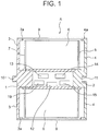
- a non-aqueous electrolyte secondary battery cell A according to exemplary embodiment 1 of this invention will be explained on the basis of Figs. 1 to 8 .
- two metal plates each of which has the shape of a quadrangle with rounded corners and is highly electro-conductive, are provided so as to face each other while being spaced apart from each other; central parts of the two metal plates project in swelling fashion and inwardly; a cross section of each of these projections is approximately quadrangular; either one of the projections and the central part of the metal plate, which is contiguous to the projection, serve as either a positive electrode or negative electrode terminal 1 or 2; and portions of the metal plates around the terminals 1 and 2 serve as flanges 3 and 4.
- the outer circumferential shape of the flanges 3 and 4 is not limited to the shape of a quadrangle with rounded corners and may be circular.
- a hollow core material 5 is formed by: making both ends of the core material 5, which is constituted by an engineering plastic externally coated with a laminate film, overlap outer circumferences of the projections of the terminals 1 and 2 that face each other with the space therebetween; and fixing both these ends onto the outer circumferences.
- a cell basic member 6 is wound around an outer circumference of the core material 5. A diameter of an outer circumference of the cell basic member 6 and diameters of the outer circumferences of the flanges 3 and 4 are almost identical.
- the core material 5 is constituted by the engineering plastic that has strength and the laminate film.
- the laminate film does not allow electrolytes to pass through.
- the laminate film is constituted by a first layer formed from high-strength material such as PET or nylon, a second layer formed from aluminum foil that has a thickness of several tens of ⁇ m and that inhibits entrance or exit of gas and moisture, and a third layer formed from material such as PP that can be heat sealed.
- a positive electrode current collector and a negative electrode current collector of the cell basic member 6 are extended to opposite directions so as to form electro-conductive, heat conductive members (hereinafter, "electro-thermal conductors") 7 and 8.
- electro-thermal conductors electro-conductive, heat conductive members
- a tip of either the electro-thermal conductor 7 or 8 is brought into contact with and fixed to the outer circumference of the projection of either the positive electrode or negative electrode terminal 1 or 2 and is connected thereto in an electrical, heat-conductive manner.
- Outer circumferential edges of the two flanges 3 and 4 have fold-back edges 3a and 4a that are oriented toward the central part of the cell. Both ends of a laminate film 9 are brought into contact with and fixed to the fold-back edges 3a and 4a and are thus wound thereonto, and the cell basic member 6 is covered by the laminate film 9.
- This laminate film has a three-layer structure that is equivalent to the structure of the laminate film constituting the core material 5.
- the cell is sealed by the laminate film 9 and the flanges 3 and 4 including the positive electrode and negative electrode terminals 1 and 2. Accordingly, the cell is provided with a function of preventing leakage of the electrolyte inside the cell to the outside, as well as efficiently transferring heat, which is generated around the electrodes inside the cell, to the positive electrode and negative electrode terminals 1 and 2 through the current collectors and the electro-thermal conductors 7 and 8, thereby enabling efficient heat dissipation.
- the battery cells A when a plurality of battery cells A are connected to one another, the battery cells A can be connected in such a manner that the terminal 1 and flange 3 of a battery cell A overlap with the terminal 2 and flange 4 of the adjacent battery cell A by fitting together the first fitting member 10 and the second fitting member 11 of the adjacent battery cells A; thus, a battery pack, even when formed by connecting a plurality of battery cells A together, will not take up extra space.
- the first and second fitting members 10 and 11 are either members that are electro-conductive and heat conductive or members that are made from the same material as the terminals 1 and 2. It is also possible to make the first fitting member 10 into a female screw and the second fitting member 11 into a male screw. Furthermore, the first and second fitting members 10 and 11 may also not be male or female screws. It suffices if these fitting members are structured so as to be fittable and connectable to each other.
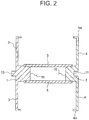
- a temperature sensor 12, voltage sensor 13, balancer 14, and Zener diode 15 which serve as a cell monitoring system.
- the temperature sensor 12, voltage sensor 13, balancer 14, and Zener diode 15 are electrically connected to the positive electrode or negative electrode terminal 1 or 2 inside the hollow part of the core material 5 via a plurality of lead wires 16 (see Fig. 2; Fig. 2 only illustrates a pair of lead wires 16 and the other pairs are not illustrated).
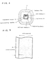
- the temperature sensor 12 is inserted into the approximate center of the engineering plastic of the core material 5 and a surface thereof is firmly adhered onto the laminate film provided on the outer side of the core material 5. Further, an inner side of the temperature sensor 12 is covered by a heat-insulating member 17.
- a distance between the surface of the temperature sensor 12 and a source of heat generation, such as the cell basic member 6, is as small as a distance equivalent to a total thickness of a thickness of the laminate film of the core material 5 plus a thickness of a separator of the cell basic member 6 (see Fig. 3 ); this enables highly accurate measurement of a temperature of the cell.
- the voltage sensor 13 has its voltmeter connected to a pair of lead wires 16 of the positive electrode and negative electrode terminals 1 and 2, in which the wires are extended from respective ends of the core material 5 (illustrated in Fig. 2 ).
- the balancer 14 is installed for the purpose of enabling 100% efficient utilization of battery capacities and prolongation of battery life by virtue of the balancer 14 keeping voltages among the plurality of battery cells A constant.
- the balancer 14 is of a passive type such that: among the battery cells A in the battery pack, battery cells A with higher voltages are detected; electric power of these battery cells A is converted into heat by means of a resistor, whereby the voltages of these battery cells A are aligned with voltages of battery cells A with lower voltages; and thereafter, the entirety of the plurality of battery cells A are charged.
- the Zener diode 15 one with a large capacity is used to prevent overcurrent. Accordingly, when the battery cell A is overcharged above a stipulated voltage, energy that is equivalent to the surplus voltage is converted into heat with the Zener diode 15 and, in a manner similar to the heat dissipation with the resistor of the balancer 14, heat is dissipated to outside the battery cell.
- the inside of the hollow core material 5 is also provided with a signal transmitter-receiver 19 that employs multiplexing.
- the signal transmitter-receiver 19 is provided with: a temperature measurement A/D converter 19a that is electrically connected with the temperature sensor 12; a voltage measurement A/D converter 19b that is electrically connected with the voltage sensor 13; a voltage-temperature information modulator 19c that modulates information pertaining to, for example, measured temperature values and measured voltage values measured by the temperature measurement A/D converter 19a and voltage measurement A/D converter 19b and transmits the result to the positive electrode or negative electrode terminal 1 or 2; and an operation instruction demodulator 19d for the balancer 14.
- the signal transmitter-receiver 19 is electrically connected to the positive electrode or negative electrode terminal 1 or 2 through a signal line 20 or 21.
- a power consumption resistor 14a that is constituted by a transistor and a resistor and converts an output received from the balancer 14 into heat.
- the Zener diode 15 for overcharge protection is provided with a resistor 15a that, when the battery cell A is overcharged above a stipulated voltage, is used to convert the energy equivalent to the surplus voltage into heat, and the Zener diode 15 is connected with power cables 24 and 25 that transmit the heat to the positive electrode or negative electrode terminal 1 or 2.
- the voltage sensor 13 is electrically connected to the positive electrode or negative electrode terminal 1 or 2 via the pair of lead wires 16 (illustrated in Fig. 8 as "voltage measurement lead wires 16").
- Measurement values of the temperature sensor 12 and voltage sensor 13 are transmitted to a battery management system (BMS), which is a device that monitors the battery pack overall, via the positive electrode or negative electrode terminal 1 or 2, and are used as command signals for control of an electric current that flows from the battery cell A or for the operation of the balancer 14.
- BMS battery management system
- this invention employs either wired communication via the terminal 1 or 2 or wireless radio-wave communication based on space propagation.
- This wired communication is a method in which values from the sensors are converted into digital and further into voltage pulse numbers according to the values, so as to be transmitted to the terminals 1 and 2.
- the voltage pulse is superimposed on the direct current of the battery cell A.
- the portion corresponding to the direct current is subtracted from a waveform that is formed in this way, it is possible to extract a pulse waveform alone.
- a specific configuration of a unit for transmitting measurement information signals of the temperature sensor 12 and voltage sensor 13 from the cell monitoring system to outside the battery cell A, or for transmitting signals from outside the battery cell A to the cell monitoring system, is not illustrated in the figures.
- This unit is provided with a signal transmitting-receiving function that uses a spread-spectrum technique in the following manner.
- a thin hole is perforated at the center of the positive electrode or negative electrode terminal 1 or 2 coaxially with the terminal 1 or 2; a non-metallic material that transmits radio waves well is inserted into the hole; then, via this material, measurement information signals of the temperature sensor 12 and voltage sensor 13 from the cell monitoring system are transmitted to outside the battery cell A or signals from outside the battery cell A are transmitted to the cell monitoring system.
- a signal receiving function that uses either wired or wireless communication and that employs time division multiplexing or multiplexing based on a spread-spectrum technique, etc. for communication signals from one or more non-aqueous electrolyte secondary battery cells A, so as to multiplex signals from a plurality of cells while avoiding interference therebetween and also to improve noise immunity.
- both sides of the positive electrode current collector formed from aluminum with a thickness of 20 ⁇ m are coated with a positive electrode active material with a thickness of 100 ⁇ m.
- This positive electrode active material employs a ternary system, into which a binder made up of polyvinylidene fluoride (6.5%) and an electrical conductor made up of carbon black (4%) have been mixed in.
- a gel-like mixture that is obtained by mixing polyvinylidene fluoride into an electrolyte that is obtained by mixing lithium hexafluorophosphate (LiPF 6 ) as a solute into a solvent that is a mixture of ethylene carbonate (EC) and propylene carbonate (PC).
- LiPF 6 lithium hexafluorophosphate
- EC ethylene carbonate
- PC propylene carbonate
- both sides of the negative electrode current collector formed from copper with a thickness of 10 ⁇ m are coated with a negative electrode active material with a thickness of 56 ⁇ m.
- This negative electrode active material is obtained by mixing into hard carbon a binder made up of polyvinylidene fluoride (4%), similarly to the positive electrode. This thickness corresponds to an amount of hard carbon that is sufficient to receive the entirety of lithium ion stored in the positive electrode during charging.
- a gel-like electrolytic solution is coated, similarly to the positive electrode.
- a separator is interposed between the aforementioned positive electrode member and negative electrode member.
- a 9 ⁇ m-thick, biaxially stretched product made from polyethylene is typically used.
- the separator serves to prevent short circuiting due to adherence of the positive and negative electrodes, retain the electrolyte, and transmit lithium ions that move between the positive and negative electrodes.
- This separator is adhered onto the entire surface that has been coated in the form of gel on the single side of each of the positive and negative electrodes.
- the cell basic member 6, which is long and band-like and has a 4-layer structure is completed and, as illustrated in Fig. 3 , wound around the outer circumference of the core material 5 having the shape of a polygonal tube.
- a band-like material that is wider than the coating surface of the battery material is used for a current collector 6a of each of the positive and negative electrodes, and a material for an active material is coated on a portion thereof. That is, the current collector 6a is coated with the active material while the end surface thereof is left uncoated. Note that although not illustrated in the figures, the respective end surfaces of the current collectors 6a onto which no active material is coated are provided on opposite sides for the positive and negative electrodes.
- the portion of the current collector 6a of each of the positive and negative electrodes on which no active material is coated is provided with cuts along the edge and the cuts are spaced apart from one another, such that the uncut portions that remain on the current collector 6a have uniform widths while the cuts become gradually wider. This is performed on each of the current collectors 6a of the positive and negative electrodes.
- the portions that remain on the current collectors 6a of the positive and negative electrodes serve as the electro-thermal conductors 7 and 8.
- the electro-thermal conductor 7 of the positive electrode is fixedly adhered to the outer circumference of the projection of the positive electrode terminal 1 and the electro-thermal conductor 8 of the negative electrode is fixedly adhered to the outer circumference of the projection of the negative electrode terminal 2.
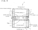
- a PTC element 18 is provided on the outer circumference of the projection of the negative electrode terminal 2.
- the rest of the configuration is equivalent to exemplary embodiment 1.
- Provision of the PTC element 18 provides the following function. That is, when there is a temperature increase, a resistance value increases so as to break a current flowing through one or more battery cells B, and when heat discharge at the Zener diode 15 exceeds the heat capacity due to overcharge or when there is external short circuiting, the battery cell(s) is (are) prevented from reaching a high temperature.
- exemplary embodiment 2 in which a plurality of the non-aqueous electrolyte secondary battery cells A are connected to one another by the first and second fitting members, it is possible to install an overcharge prevention device in which overcharge prevention switches, which automatically stop charging on the basis of a voltage value measured in the cell monitoring system, are attached to the positive and negative electrodes of the battery pack and the switches are actuated at a voltage that is 0.02 ⁇ 0.01 V lower than the voltage value at which the Zener diode starts discharge of the overcharge current.
- the Zener diode 15 is inserted inside the cell monitoring system so as to convert the overcharge electric power into heat, which is dissipated to outside the battery cell. Further, to cope with leakage of an electrolyte solution, the electrolyte is made into a gel, which greatly enhances safety. Furthermore, the terminals are provided with flanges and fold-back edges and a laminate film is passed over the fold-back edges by surface contact so as to cover the battery cell; by taking such double-measure, liquid leakage is prevented.
- portions obtained by extending the positive electrode and negative electrode current collectors of the cell basic member are made into electro-thermal conductors 7 and 8 and are used as electro-thermal conductors 7 and 8 to express the functions thereof, the current collectors may also remain as current collectors.
Landscapes
- Chemical & Material Sciences (AREA)
- Chemical Kinetics & Catalysis (AREA)
- Electrochemistry (AREA)
- General Chemical & Material Sciences (AREA)
- Engineering & Computer Science (AREA)
- Manufacturing & Machinery (AREA)
- Microelectronics & Electronic Packaging (AREA)
- Power Engineering (AREA)
- Physics & Mathematics (AREA)
- General Physics & Mathematics (AREA)
- Secondary Cells (AREA)
- Materials Engineering (AREA)
- Condensed Matter Physics & Semiconductors (AREA)
- Dispersion Chemistry (AREA)
- Inorganic Chemistry (AREA)
- Connection Of Batteries Or Terminals (AREA)
- Charge And Discharge Circuits For Batteries Or The Like (AREA)
- Sealing Battery Cases Or Jackets (AREA)
- Battery Mounting, Suspending (AREA)
Claims (14)
- Sekundärbatteriezelle mit nichtwässrigem Elektrolyten, wobei in einer Sekundärbatterie mit nichtwässrigem Elektrolyten die Zelle selbst die Form eines Zylinders oder eines Mehrkantrohrs mit abgerundeten Ecken aufweist; ein hartes Kernmaterial (5) in einer Mitte der Zelle vorgesehen ist, das Kernmaterial (5) ein Isolierkörper mit einem kreisförmigen oder viereckigen Querschnitt und mit der Form eines Hohlrohrs ist, wobei das Kernmaterial (5) die Permeation eines Elektrolyten verhindert; ein Zellenüberwachungssystem innerhalb eines Hohlteils des Kernmaterials vorgesehen ist, wobei das Zellenüberwachungssystem einen Spannungssensor (13), einen Temperatursensor (12) und einen Ausgleicher (14) für die Zelle umfasst, wobei der Spannungssensor (13), der Temperatursensor (12) und der Ausgleicher (14) am Zellenüberwachungssystem angebracht sind; ein Zellenbasiselement (6), das durch ein positives Elektrodenelement (1), einen Separator und ein negatives Elektrodenelement (2) gebildet wird, für die Sekundärbatteriezelle mit nichtwässrigem Elektrolyten auf das Kernmaterial gewickelt oder laminiert ist und als Schaft dient; ein elektrisch leitender Anschluss (10), der mit einem Stromabnehmer des positiven Elektrodenelements (1) elektrisch verbunden ist, und ein elektrisch leitender Anschluss (11), der mit einem Stromabnehmer des negativen Elektrodenelements (2) elektrisch verbunden ist, auf der Zelle vorgesehen sind, wobei die Anschlüsse (10, 11) zu äußeren Seiten der Zelle freigelegt sind; und der Temperatursensor (12) des Zellenüberwachungssystems in einem mittigen Teil des Hohlteils des Kernmaterials (5) angebracht ist, indem er fest an das Kernmaterial (5) geklebt ist, und der Ausgleicher (14) von einem passiven Typ ist, derart dass unter einer Vielzahl von Batteriezellen in einem Batteriesatz Batteriezellen mit höheren Spannungen erkannt werden und die elektrische Leistung dieser Batteriezellen mittels eines Widerstands (14a) in Wärme umgewandelt wird, wodurch die Spannungen dieser Batteriezellen an Spannungen von Batteriezellen mit niedrigeren Spannungen angeglichen werden, und danach die Gesamtheit der Vielzahl von Zellen geladen wird, und die Sekundärbatteriezelle mit nichtwässrigem Elektrolyten mit einem Draht (16) verbunden ist, der die am Ausgleicher (14) erzeugte Wärme über den Anschluss (10) der positiven Elektrode (1) oder den Anschluss (11) der negativen Elektrode (2) ableitet.
- Sekundärbatteriezelle mit nichtwässrigem Elektrolyten nach Anspruch 1, wobei eine Zener-Diode (15), die überschüssige elektrische Leistung zum Zeitpunkt von Überladung verbraucht, innerhalb des Zellenüberwachungssystems vorgesehen ist, und die Sekundärbatteriezelle mit nichtwässrigem Elektrolyten mit einem Draht (16) verbunden ist, der die an der Zener-Diode (15) erzeugte Wärme über den Anschluss (10) der positiven Elektrode (1) oder den Anschluss (11) der negativen Elektrode (2) ableitet.
- Sekundärbatteriezelle mit nichtwässrigem Elektrolyten entweder nach Anspruch 1 oder 2, wobei die Anschlüsse (10, 11) auf beiden Seiten des Kernmaterials (5) konzentrisch mit dem Kernmaterial (5) vorgesehen sind, wobei die Anschlüsse (10, 11) für die positive Elektrode (1) bzw. die negative Elektrode (2) verwendet werden; und die Stromabnehmer des positiven Elektrodenelements (1) und des negativen Elektrodenelements (2) sich auf einander gegenüberliegenden Seiten in Richtung der Anschlüsse (10, 11) erstrecken, wobei die Stromabnehmer in einer direkten, elektrischen und wärmeleitenden Weise mit den Anschlüssen (10, 11) der positiven Elektrode (1) bzw. der negativen Elektrode (2) verbunden sind.
- Sekundärbatteriezelle mit nichtwässrigem Elektrolyten nach Anspruch 3, wobei ein Flansch (3, 4) in einem Stück mit jedem der Anschlüsse (10, 11) der positiven Elektrode (1) und der negativen Elektrode (2) vorgesehen ist, wobei die Flansche (3, 4) auf den entsprechenden Anschlüssen (10, 11) zentriert sind, die Flansche (3, 4) und die Anschlüsse (10, 11) aus dem gleichen Material hergestellt sind, die Flansche (3, 4) jeweils beide Enden des gewickelten oder laminierten Zellenbasiselements (6) abdecken, das durch das positive Elektrodenelement (1), den Separator und das negative Elektrodenelement (2) gebildet wird; eine zurückgefaltete Kante auf einer Außenumfangskante eines jeden der Flansche vorgesehen ist, wobei die zurückgefalteten Kanten in Richtung der Zelle orientiert sind; und die Sekundärbatteriezelle mit nichtwässrigem Elektrolyten einen Laminatfilm (9) umfasst, der auf der Sekundärbatteriezelle mit nichtwässrigem Elektrolyten installiert ist, wobei beide Enden des Laminatfilms (9) jeweils auf beiden Seiten an die zurückgefalteten Kanten der Flansche (3, 4) geklebt sind, der Laminatfilm (9) die Zelle abdeckt, der Laminatfilm (9) das Entweichen eines Elektrolyten von innerhalb der Zelle nach außerhalb der Zelle verhindert.
- Sekundärbatteriezelle mit nichtwässrigem Elektrolyten nach einem der Ansprüche 1 bis 4, wobei ein elektrisch leitendes erstes Passelement auf einem äußeren Endteil des Anschlusses (10) der positiven Elektrode (1) vorgesehen ist, wobei das erste Passelement in einem Stück mit dem Anschluss (10) der positiven Elektrode (1) ist; ein elektrisch leitendes zweites Passelement auf einem äußeren Endteil des Anschlusses (11) für die negative Elektrode (2) vorgesehen ist, wobei das erste Passelement ausgelegt ist, um in das zweite Passelement eingepasst zu werden.
- Sekundärbatteriezelle mit nichtwässrigem Elektrolyten nach Anspruch 5, wobei die Passabschnitte des ersten Passelements und des zweiten Passelements beschichtet sind, um elektrolytische Korrosion zu verhindern.
- Sekundärbatteriezelle mit nichtwässrigem Elektrolyten nach einem der Ansprüche 1 bis 6, wobei ein Element zwischen dem Anschluss (10) und dem Stromabnehmer der positiven Elektrode (1) oder dem Anschluss (11) und dem Stromabnehmer der negativen Elektrode (2) installiert ist, wobei das Element ein PTC-Element oder dergleichen ist, wobei ein Widerstandswert des Elements aufgrund von Wärme stark ansteigt; und das Element die Sekundärbatteriezelle mit nichtwässrigem Elektrolyten zum Zeitpunkt eines Temperaturanstiegs innerhalb der Batteriezelle mit einer Funktion zum Unterbrechen eines elektrischen Stroms versieht, der durch die Batteriezelle und eine andere Batteriezelle fließt.
- Sekundärbatteriezelle mit nichtwässrigem Elektrolyten nach Anspruch 7, wobei Kontaktabschnitte des Anschlusses, des Elements mit dem stark ansteigenden Widerstandswert und des Stromabnehmers beschichtet sind, um elektrolytische Korrosion zu verhindern, wobei der Anschluss, das Element und der Stromabnehmer an den Kontaktabschnitten miteinander in Kontakt treten.
- Sekundärbatteriezelle mit nichtwässrigem Elektrolyten nach einem der Ansprüche 1 bis 8, wobei ein Elektrolyt des Zellenbasiselements ein Gel ist, und der Gel-Elektrolyt auf jeweilige Außenumfangsflächen eines aktiven Materials der positiven Elektrode und ein aktives Material der negativen Elektrode des Zellenbasiselements aufgetragen ist.
- Sekundärbatteriezelle mit nichtwässrigem Elektrolyten nach einem der Ansprüche 1 bis 9, wobei eine Einheit, die zum Senden von Messinformationssignalen des Temperatursensors (12) und des Spannungssensors (13) vom Zellenüberwachungssystem nach außerhalb der Batteriezelle oder zum Senden von Signalen von außerhalb der Zelle an das Zellenüberwachungssystem ausgelegt ist, entweder drahtgebundene Kommunikation über den Anschluss (10, 11) der positiven Elektrode (1) oder der negativen Elektrode (2) oder drahtlose Kommunikation unter Verwendung von Funkwellen einsetzt.
- Sekundärbatteriezelle mit nichtwässrigem Elektrolyten nach Anspruch 10, wobei die Einheit, die zum Senden von Messinformationssignalen des Temperatursensors (12) und des Spannungssensors (13) vom Zellenüberwachungssystem nach außerhalb der Batteriezelle oder zum Senden von Signalen von außerhalb der Zelle an das Zellenüberwachungssystem ausgelegt ist, mit einer Funktion zum Senden/Empfangen von Signalen unter Verwendung eines Frequenzspreizverfahrens versehen ist, wobei die Funktion zum Senden/Empfangen von Signalen durch Bohren eines kleinen Lochs in der Mitte des Anschlusses (10, 11) der positiven Elektrode (1) oder der negativen Elektrode (2) koaxial mit diesem Anschluss und durch Einführen eines nichtmetallischen Materials mit hoher Funkwellendurchlässigkeit in das Loch erreicht wird; und über dieses Material die Messinformationssignale des Temperatursensors (12) und des Spannungssensors (13) vom Zellenüberwachungssystem nach außerhalb der Batteriezelle gesendet werden oder die Signale von außerhalb der Zelle an das Zellenüberwachungssystem gesendet werden.
- Sekundärbatteriezelle mit nichtwässrigem Elektrolyten entweder nach Anspruch 10 oder 11, die mit einer Funktion zum Senden/Empfangen von Signalen entweder unter Verwendung von drahtgebundener oder drahtloser Kommunikation und Einsetzen des Zeitmultiplex- oder Multiplexverfahrens basierend auf einem Frequenzspreizverfahrens für Kommunikationssignale von einer oder mehreren Sekundärbatteriezellen mit nichtwässrigem Elektrolyten versehen ist.
- Sekundärbatteriesatz mit nichtwässrigem Elektrolyten, umfassend eine Vielzahl von Sekundärbatteriezellen mit nichtwässrigem Elektrolyten nach einem der Ansprüche 1 bis 12, wobei die Sekundärbatteriezellen mit nichtwässrigem Elektrolyten elektrisch miteinander verbunden sind, wobei der Batteriesatz eine Überladungsschutzvorrichtung umfasst; die Überladungsschutzvorrichtung einen Überladungsschutzschalter, der an einer positiven Elektrode des Batteriesatzes angebracht ist, und einen Überladungsschutzschalter umfasst, der an einer negativen Elektrode des Batteriesatzes angebracht ist; wobei die Überladungsschutzschalter so ausgelegt sind, dass sie anhand eines Spannungswerts, der im Zellenüberwachungssystem gemessen wird, das Laden automatisch stoppen.
- Sekundärbatteriesatz mit nichtwässrigem Elektrolyten, umfassend eine Vielzahl von Sekundärbatteriezellen mit nichtwässrigem Elektrolyten nach einem der Ansprüche 1 bis 12, wobei die Sekundärbatteriezellen mit nichtwässrigem Elektrolyten elektrisch miteinander verbunden sind, wobei der Batteriesatz einen externen Kurzschlussschutzschalter umfasst, der ein Strommessgerät umfasst; wobei das Strommessgerät entweder an einer positiven Elektrode oder einer negativen Elektrode des Batteriesatzes angebracht ist; und wobei, wenn ein elektrischer Strom fließt, der einen vorbestimmten Wert des elektrischen Stroms überschreitet, der externe Kurzschlussschutzschalter den elektrischen Strom automatisch stoppt.
Applications Claiming Priority (2)
| Application Number | Priority Date | Filing Date | Title |
|---|---|---|---|
| JP2015222522A JP6678989B2 (ja) | 2015-11-12 | 2015-11-12 | 非水電解液二次電池セル及びこれを用いた組電池 |
| PCT/JP2016/083556 WO2017082399A1 (ja) | 2015-11-12 | 2016-11-11 | 非水電解液二次電池セル及びこれを用いた組電池 |
Publications (3)
| Publication Number | Publication Date |
|---|---|
| EP3376582A1 EP3376582A1 (de) | 2018-09-19 |
| EP3376582A4 EP3376582A4 (de) | 2019-05-22 |
| EP3376582B1 true EP3376582B1 (de) | 2020-11-04 |
Family
ID=58695461
Family Applications (1)
| Application Number | Title | Priority Date | Filing Date |
|---|---|---|---|
| EP16864360.9A Active EP3376582B1 (de) | 2015-11-12 | 2016-11-11 | Sekundärbatteriezellen mit wasserfreiem elektrolyt und damit hergestellte batterie damit |
Country Status (6)
| Country | Link |
|---|---|
| US (1) | US10707542B2 (de) |
| EP (1) | EP3376582B1 (de) |
| JP (1) | JP6678989B2 (de) |
| KR (1) | KR20180075551A (de) |
| CN (1) | CN108352578A (de) |
| WO (1) | WO2017082399A1 (de) |
Families Citing this family (18)
| Publication number | Priority date | Publication date | Assignee | Title |
|---|---|---|---|---|
| JP2017067761A (ja) * | 2015-10-01 | 2017-04-06 | 株式会社デンソー | 異常兆候診断装置 |
| DE102016225691A1 (de) * | 2016-12-20 | 2018-06-21 | Bayerische Motoren Werke Aktiengesellschaft | Hochvolt-Batterie für ein Kraftfahrzeug, insbesondere für einen Kraftwagen |
| KR102394741B1 (ko) * | 2018-11-29 | 2022-05-06 | 주식회사 엘지에너지솔루션 | 열 방출이 개선된 배터리 모듈, 이러한 배터리 모듈을 포함하는 배터리 팩 및 이러한 배터리 팩을 포함하는 자동차 |
| CN110010344B (zh) * | 2019-05-08 | 2024-11-26 | 奕顺龙能源科技(北京)有限公司 | 储能元件以及电能存储装置 |
| JP7234969B2 (ja) * | 2020-02-17 | 2023-03-08 | トヨタ自動車株式会社 | 電池システムおよび電池の異常判定方法 |
| KR102640844B1 (ko) | 2020-04-14 | 2024-02-27 | 삼성에스디아이 주식회사 | 배터리 팩 |
| EP3916826A1 (de) * | 2020-05-29 | 2021-12-01 | VARTA Microbattery GmbH | Elektrochemische zelle |
| EP3945617B1 (de) * | 2020-07-28 | 2025-04-23 | VARTA Microbattery GmbH | Elektrochemische energiespeicherzelle |
| CN116235340A (zh) * | 2020-09-24 | 2023-06-06 | 森萨塔科技公司 | 用于电池内感测的通过电池单元的信号传输系统和方法 |
| EP4007038A4 (de) * | 2020-09-30 | 2023-05-03 | Tianjin Lishen Battery Joint-Stock Co., Ltd. | Stiftartiges packmodul für lithium-ionen-batterie |
| CN112151854A (zh) * | 2020-09-30 | 2020-12-29 | 天津力神电池股份有限公司 | 一种锂离子电池用插针式pack组件 |
| EP4009415A4 (de) * | 2020-09-30 | 2023-05-03 | Tianjin Lishen Battery Joint-Stock Co., Ltd. | Batterie |
| JP7459833B2 (ja) * | 2021-03-31 | 2024-04-02 | トヨタ自動車株式会社 | 蓄電セル |
| CN216563271U (zh) * | 2021-09-18 | 2022-05-17 | 微宏动力系统(湖州)有限公司 | 卷绕式电芯及卷绕电池 |
| CN116802862A (zh) * | 2021-10-05 | 2023-09-22 | 株式会社Lg新能源 | 电极组件、包括该电极组件的圆柱形电池以及系统 |
| KR102680074B1 (ko) * | 2022-03-30 | 2024-07-02 | 주식회사 엘지에너지솔루션 | 이차전지 모듈 |
| CN118451588A (zh) * | 2022-09-29 | 2024-08-06 | 宁德时代新能源科技股份有限公司 | 电池单体、电池以及用电装置 |
| CN117936929B (zh) * | 2023-12-27 | 2025-04-15 | 中国第一汽车股份有限公司 | 软包电池单元及具有其的车辆 |
Family Cites Families (16)
| Publication number | Priority date | Publication date | Assignee | Title |
|---|---|---|---|---|
| JPH07272748A (ja) | 1994-03-31 | 1995-10-20 | Japan Storage Battery Co Ltd | 電池装置 |
| JPH10214613A (ja) | 1997-01-30 | 1998-08-11 | Hitachi Ltd | 非水電解液二次電池とこれを用いた組電池 |
| JP2000277176A (ja) * | 1999-03-24 | 2000-10-06 | Ngk Insulators Ltd | リチウム二次電池及び使用方法 |
| JP2001313078A (ja) * | 2000-04-27 | 2001-11-09 | Shin Kobe Electric Mach Co Ltd | 密閉型非水二次電池及び組電池 |
| US6475662B1 (en) * | 2000-06-05 | 2002-11-05 | Eagle-Picher Technologies, Llc | Thermal battery |
| JP4499680B2 (ja) * | 2005-03-30 | 2010-07-07 | 三星エスディアイ株式会社 | 円筒形リチウムイオン二次電池 |
| CN101589503B (zh) * | 2007-11-30 | 2012-05-30 | 株式会社村田制作所 | 电池模块及充电模块 |
| CN101577344B (zh) * | 2009-06-11 | 2011-04-20 | 珠海银通交通能源投资有限公司 | 动力电池 |
| JP2012212506A (ja) | 2009-07-01 | 2012-11-01 | Hitachi Maxell Ltd | ラミネート形電池 |
| JP5218565B2 (ja) * | 2010-01-13 | 2013-06-26 | トヨタ自動車株式会社 | 電池の製造方法 |
| JP5796289B2 (ja) * | 2010-11-26 | 2015-10-21 | ソニー株式会社 | 二次電池セル、電池パック及び電力消費機器 |
| JP2012174344A (ja) * | 2011-02-17 | 2012-09-10 | Hitachi Ltd | 電池およびその製造方法 |
| US20130136964A1 (en) * | 2011-11-30 | 2013-05-30 | Johnson Controls Technology Company | Electrochemical cell having a safety device |
| US9356327B2 (en) * | 2011-12-19 | 2016-05-31 | Johnson Controls Technology Company | Unitary energy storage and sensing batteries |
| JP5496245B2 (ja) * | 2012-04-13 | 2014-05-21 | 三菱電機株式会社 | 組電池を用いた電源システム |
| JP5679233B2 (ja) * | 2012-11-02 | 2015-03-04 | Semitec株式会社 | 電池寿命予測装置及び電池寿命予測システム |
-
2015
- 2015-11-12 JP JP2015222522A patent/JP6678989B2/ja not_active Expired - Fee Related
-
2016
- 2016-11-11 WO PCT/JP2016/083556 patent/WO2017082399A1/ja not_active Ceased
- 2016-11-11 EP EP16864360.9A patent/EP3376582B1/de active Active
- 2016-11-11 CN CN201680065968.XA patent/CN108352578A/zh active Pending
- 2016-11-11 US US15/774,107 patent/US10707542B2/en not_active Expired - Fee Related
- 2016-11-11 KR KR1020187013603A patent/KR20180075551A/ko not_active Withdrawn
Non-Patent Citations (1)
| Title |
|---|
| None * |
Also Published As
| Publication number | Publication date |
|---|---|
| KR20180075551A (ko) | 2018-07-04 |
| EP3376582A1 (de) | 2018-09-19 |
| JP6678989B2 (ja) | 2020-04-15 |
| EP3376582A4 (de) | 2019-05-22 |
| JP2017091890A (ja) | 2017-05-25 |
| US20180331399A1 (en) | 2018-11-15 |
| US10707542B2 (en) | 2020-07-07 |
| CN108352578A (zh) | 2018-07-31 |
| WO2017082399A1 (ja) | 2017-05-18 |
Similar Documents
| Publication | Publication Date | Title |
|---|---|---|
| EP3376582B1 (de) | Sekundärbatteriezellen mit wasserfreiem elektrolyt und damit hergestellte batterie damit | |
| US9653724B2 (en) | Secondary battery, and secondary battery module and secondary battery pack comprising the same | |
| CN107112494B (zh) | 电池、电池组、电子仪器、电动汽车、电力存储装置以及电力系统 | |
| KR101539691B1 (ko) | 파우치형 이차 전지의 프레임, 이를 포함하는 배터리 팩 및 배터리 팩의 제조 방법 | |
| EP2043177B1 (de) | Schutzschalttafel und Batteriepack damit | |
| KR101512549B1 (ko) | 편평형 전지 | |
| KR102288121B1 (ko) | 파우치 형 이차 전지 | |
| US11936068B2 (en) | Battery, battery pack, electronic device, electromotive vehicle, power storage device, and electric power system | |
| JP5458898B2 (ja) | 固体電池スタック | |
| EP3641045B1 (de) | Kabelartige batterie | |
| EP4510317A1 (de) | Batterie und elektronische vorrichtung | |
| US20090029246A1 (en) | Pouch-type secondary battery | |
| KR20130089376A (ko) | 온도 센서를 포함하는 이차전지 | |
| KR20230030414A (ko) | 연결 와이어 및 이를 포함하는 전지팩 | |
| KR20140137603A (ko) | 파우치형 외장재 | |
| KR101558702B1 (ko) | 고전압 배터리 | |
| KR102006203B1 (ko) | 절연성이 개선된 파우치 외장 부재 및 이를 포함하는 파우치형 이차 전지 | |
| US7166387B2 (en) | Thin battery with an electrode having a higher strength base portion than a tip portion | |
| US20250070406A1 (en) | Battery and electronic device | |
| CN219696531U (zh) | 紧固结构、连接组件、电池和用电装置 | |
| KR20170060937A (ko) | 이차 전지 | |
| KR101458259B1 (ko) | 파우치형 이차전지 및 그 제조방법 | |
| KR102227806B1 (ko) | 2차 전지 | |
| EP4068474A1 (de) | Elektrochemische zelle | |
| KR102301664B1 (ko) | 이차전지 |
Legal Events
| Date | Code | Title | Description |
|---|---|---|---|
| STAA | Information on the status of an ep patent application or granted ep patent |
Free format text: STATUS: THE INTERNATIONAL PUBLICATION HAS BEEN MADE |
|
| PUAI | Public reference made under article 153(3) epc to a published international application that has entered the european phase |
Free format text: ORIGINAL CODE: 0009012 |
|
| STAA | Information on the status of an ep patent application or granted ep patent |
Free format text: STATUS: REQUEST FOR EXAMINATION WAS MADE |
|
| 17P | Request for examination filed |
Effective date: 20180508 |
|
| AK | Designated contracting states |
Kind code of ref document: A1 Designated state(s): AL AT BE BG CH CY CZ DE DK EE ES FI FR GB GR HR HU IE IS IT LI LT LU LV MC MK MT NL NO PL PT RO RS SE SI SK SM TR |
|
| AX | Request for extension of the european patent |
Extension state: BA ME |
|
| DAV | Request for validation of the european patent (deleted) | ||
| DAX | Request for extension of the european patent (deleted) | ||
| A4 | Supplementary search report drawn up and despatched |
Effective date: 20190424 |
|
| RIC1 | Information provided on ipc code assigned before grant |
Ipc: H01M 2/30 20060101ALI20190416BHEP Ipc: H01M 10/42 20060101ALI20190416BHEP Ipc: H01M 10/0587 20100101ALI20190416BHEP Ipc: H01M 10/04 20060101ALI20190416BHEP Ipc: H01M 10/643 20140101ALI20190416BHEP Ipc: H01M 2/34 20060101ALI20190416BHEP Ipc: H01M 10/48 20060101ALI20190416BHEP Ipc: H01M 10/0585 20100101AFI20190416BHEP Ipc: H01M 10/613 20140101ALI20190416BHEP Ipc: H02J 7/00 20060101ALI20190416BHEP Ipc: H01M 10/052 20100101ALI20190416BHEP Ipc: H01M 10/654 20140101ALI20190416BHEP Ipc: H01M 10/44 20060101ALN20190416BHEP |
|
| RIC1 | Information provided on ipc code assigned before grant |
Ipc: H01M 10/0587 20100101ALI20200331BHEP Ipc: H01M 10/04 20060101ALI20200331BHEP Ipc: H01M 10/643 20140101ALI20200331BHEP Ipc: H01M 10/48 20060101ALI20200331BHEP Ipc: H01M 10/613 20140101ALI20200331BHEP Ipc: H01M 10/052 20100101ALI20200331BHEP Ipc: H01M 2/34 20060101ALI20200331BHEP Ipc: H01M 10/44 20060101ALN20200331BHEP Ipc: H01M 10/0585 20100101AFI20200331BHEP Ipc: H02J 7/00 20060101ALI20200331BHEP Ipc: H01M 2/30 20060101ALI20200331BHEP Ipc: H01M 10/654 20140101ALI20200331BHEP Ipc: H01M 10/42 20060101ALI20200331BHEP |
|
| GRAP | Despatch of communication of intention to grant a patent |
Free format text: ORIGINAL CODE: EPIDOSNIGR1 |
|
| STAA | Information on the status of an ep patent application or granted ep patent |
Free format text: STATUS: GRANT OF PATENT IS INTENDED |
|
| RIC1 | Information provided on ipc code assigned before grant |
Ipc: H01M 10/643 20140101ALI20200512BHEP Ipc: H01M 10/42 20060101ALI20200512BHEP Ipc: H01M 10/654 20140101ALI20200512BHEP Ipc: H01M 10/48 20060101ALI20200512BHEP Ipc: H01M 10/0587 20100101ALI20200512BHEP Ipc: H01M 10/052 20100101ALI20200512BHEP Ipc: H02J 7/00 20060101ALI20200512BHEP Ipc: H01M 2/30 20060101ALI20200512BHEP Ipc: H01M 2/34 20060101ALI20200512BHEP Ipc: H01M 10/0585 20100101AFI20200512BHEP Ipc: H01M 10/613 20140101ALI20200512BHEP Ipc: H01M 10/04 20060101ALI20200512BHEP Ipc: H01M 10/44 20060101ALN20200512BHEP |
|
| INTG | Intention to grant announced |
Effective date: 20200529 |
|
| GRAS | Grant fee paid |
Free format text: ORIGINAL CODE: EPIDOSNIGR3 |
|
| GRAA | (expected) grant |
Free format text: ORIGINAL CODE: 0009210 |
|
| STAA | Information on the status of an ep patent application or granted ep patent |
Free format text: STATUS: THE PATENT HAS BEEN GRANTED |
|
| AK | Designated contracting states |
Kind code of ref document: B1 Designated state(s): AL AT BE BG CH CY CZ DE DK EE ES FI FR GB GR HR HU IE IS IT LI LT LU LV MC MK MT NL NO PL PT RO RS SE SI SK SM TR |
|
| REG | Reference to a national code |
Ref country code: GB Ref legal event code: FG4D |
|
| REG | Reference to a national code |
Ref country code: CH Ref legal event code: EP |
|
| REG | Reference to a national code |
Ref country code: AT Ref legal event code: REF Ref document number: 1332012 Country of ref document: AT Kind code of ref document: T Effective date: 20201115 |
|
| REG | Reference to a national code |
Ref country code: IE Ref legal event code: FG4D |
|
| REG | Reference to a national code |
Ref country code: DE Ref legal event code: R096 Ref document number: 602016047442 Country of ref document: DE |
|
| REG | Reference to a national code |
Ref country code: NL Ref legal event code: MP Effective date: 20201104 |
|
| REG | Reference to a national code |
Ref country code: AT Ref legal event code: MK05 Ref document number: 1332012 Country of ref document: AT Kind code of ref document: T Effective date: 20201104 |
|
| PG25 | Lapsed in a contracting state [announced via postgrant information from national office to epo] |
Ref country code: FI Free format text: LAPSE BECAUSE OF FAILURE TO SUBMIT A TRANSLATION OF THE DESCRIPTION OR TO PAY THE FEE WITHIN THE PRESCRIBED TIME-LIMIT Effective date: 20201104 Ref country code: GR Free format text: LAPSE BECAUSE OF FAILURE TO SUBMIT A TRANSLATION OF THE DESCRIPTION OR TO PAY THE FEE WITHIN THE PRESCRIBED TIME-LIMIT Effective date: 20210205 Ref country code: PT Free format text: LAPSE BECAUSE OF FAILURE TO SUBMIT A TRANSLATION OF THE DESCRIPTION OR TO PAY THE FEE WITHIN THE PRESCRIBED TIME-LIMIT Effective date: 20210304 Ref country code: RS Free format text: LAPSE BECAUSE OF FAILURE TO SUBMIT A TRANSLATION OF THE DESCRIPTION OR TO PAY THE FEE WITHIN THE PRESCRIBED TIME-LIMIT Effective date: 20201104 Ref country code: NO Free format text: LAPSE BECAUSE OF FAILURE TO SUBMIT A TRANSLATION OF THE DESCRIPTION OR TO PAY THE FEE WITHIN THE PRESCRIBED TIME-LIMIT Effective date: 20210204 |
|
| PG25 | Lapsed in a contracting state [announced via postgrant information from national office to epo] |
Ref country code: SE Free format text: LAPSE BECAUSE OF FAILURE TO SUBMIT A TRANSLATION OF THE DESCRIPTION OR TO PAY THE FEE WITHIN THE PRESCRIBED TIME-LIMIT Effective date: 20201104 Ref country code: AT Free format text: LAPSE BECAUSE OF FAILURE TO SUBMIT A TRANSLATION OF THE DESCRIPTION OR TO PAY THE FEE WITHIN THE PRESCRIBED TIME-LIMIT Effective date: 20201104 Ref country code: ES Free format text: LAPSE BECAUSE OF FAILURE TO SUBMIT A TRANSLATION OF THE DESCRIPTION OR TO PAY THE FEE WITHIN THE PRESCRIBED TIME-LIMIT Effective date: 20201104 Ref country code: LV Free format text: LAPSE BECAUSE OF FAILURE TO SUBMIT A TRANSLATION OF THE DESCRIPTION OR TO PAY THE FEE WITHIN THE PRESCRIBED TIME-LIMIT Effective date: 20201104 Ref country code: IS Free format text: LAPSE BECAUSE OF FAILURE TO SUBMIT A TRANSLATION OF THE DESCRIPTION OR TO PAY THE FEE WITHIN THE PRESCRIBED TIME-LIMIT Effective date: 20210304 Ref country code: PL Free format text: LAPSE BECAUSE OF FAILURE TO SUBMIT A TRANSLATION OF THE DESCRIPTION OR TO PAY THE FEE WITHIN THE PRESCRIBED TIME-LIMIT Effective date: 20201104 Ref country code: BG Free format text: LAPSE BECAUSE OF FAILURE TO SUBMIT A TRANSLATION OF THE DESCRIPTION OR TO PAY THE FEE WITHIN THE PRESCRIBED TIME-LIMIT Effective date: 20210204 |
|
| REG | Reference to a national code |
Ref country code: DE Ref legal event code: R119 Ref document number: 602016047442 Country of ref document: DE |
|
| REG | Reference to a national code |
Ref country code: LT Ref legal event code: MG9D |
|
| PG25 | Lapsed in a contracting state [announced via postgrant information from national office to epo] |
Ref country code: HR Free format text: LAPSE BECAUSE OF FAILURE TO SUBMIT A TRANSLATION OF THE DESCRIPTION OR TO PAY THE FEE WITHIN THE PRESCRIBED TIME-LIMIT Effective date: 20201104 |
|
| REG | Reference to a national code |
Ref country code: CH Ref legal event code: PL |
|
| PG25 | Lapsed in a contracting state [announced via postgrant information from national office to epo] |
Ref country code: RO Free format text: LAPSE BECAUSE OF FAILURE TO SUBMIT A TRANSLATION OF THE DESCRIPTION OR TO PAY THE FEE WITHIN THE PRESCRIBED TIME-LIMIT Effective date: 20201104 Ref country code: SK Free format text: LAPSE BECAUSE OF FAILURE TO SUBMIT A TRANSLATION OF THE DESCRIPTION OR TO PAY THE FEE WITHIN THE PRESCRIBED TIME-LIMIT Effective date: 20201104 Ref country code: CZ Free format text: LAPSE BECAUSE OF FAILURE TO SUBMIT A TRANSLATION OF THE DESCRIPTION OR TO PAY THE FEE WITHIN THE PRESCRIBED TIME-LIMIT Effective date: 20201104 Ref country code: EE Free format text: LAPSE BECAUSE OF FAILURE TO SUBMIT A TRANSLATION OF THE DESCRIPTION OR TO PAY THE FEE WITHIN THE PRESCRIBED TIME-LIMIT Effective date: 20201104 Ref country code: LT Free format text: LAPSE BECAUSE OF FAILURE TO SUBMIT A TRANSLATION OF THE DESCRIPTION OR TO PAY THE FEE WITHIN THE PRESCRIBED TIME-LIMIT Effective date: 20201104 Ref country code: LU Free format text: LAPSE BECAUSE OF NON-PAYMENT OF DUE FEES Effective date: 20201111 Ref country code: SM Free format text: LAPSE BECAUSE OF FAILURE TO SUBMIT A TRANSLATION OF THE DESCRIPTION OR TO PAY THE FEE WITHIN THE PRESCRIBED TIME-LIMIT Effective date: 20201104 |
|
| REG | Reference to a national code |
Ref country code: BE Ref legal event code: MM Effective date: 20201130 |
|
| PG25 | Lapsed in a contracting state [announced via postgrant information from national office to epo] |
Ref country code: CH Free format text: LAPSE BECAUSE OF NON-PAYMENT OF DUE FEES Effective date: 20201130 Ref country code: DK Free format text: LAPSE BECAUSE OF FAILURE TO SUBMIT A TRANSLATION OF THE DESCRIPTION OR TO PAY THE FEE WITHIN THE PRESCRIBED TIME-LIMIT Effective date: 20201104 Ref country code: MC Free format text: LAPSE BECAUSE OF FAILURE TO SUBMIT A TRANSLATION OF THE DESCRIPTION OR TO PAY THE FEE WITHIN THE PRESCRIBED TIME-LIMIT Effective date: 20201104 Ref country code: LI Free format text: LAPSE BECAUSE OF NON-PAYMENT OF DUE FEES Effective date: 20201130 |
|
| PLBE | No opposition filed within time limit |
Free format text: ORIGINAL CODE: 0009261 |
|
| STAA | Information on the status of an ep patent application or granted ep patent |
Free format text: STATUS: NO OPPOSITION FILED WITHIN TIME LIMIT |
|
| 26N | No opposition filed |
Effective date: 20210805 |
|
| GBPC | Gb: european patent ceased through non-payment of renewal fee |
Effective date: 20210204 |
|
| PG25 | Lapsed in a contracting state [announced via postgrant information from national office to epo] |
Ref country code: IT Free format text: LAPSE BECAUSE OF FAILURE TO SUBMIT A TRANSLATION OF THE DESCRIPTION OR TO PAY THE FEE WITHIN THE PRESCRIBED TIME-LIMIT Effective date: 20201104 Ref country code: FR Free format text: LAPSE BECAUSE OF NON-PAYMENT OF DUE FEES Effective date: 20210104 Ref country code: AL Free format text: LAPSE BECAUSE OF FAILURE TO SUBMIT A TRANSLATION OF THE DESCRIPTION OR TO PAY THE FEE WITHIN THE PRESCRIBED TIME-LIMIT Effective date: 20201104 Ref country code: IE Free format text: LAPSE BECAUSE OF NON-PAYMENT OF DUE FEES Effective date: 20201111 Ref country code: NL Free format text: LAPSE BECAUSE OF FAILURE TO SUBMIT A TRANSLATION OF THE DESCRIPTION OR TO PAY THE FEE WITHIN THE PRESCRIBED TIME-LIMIT Effective date: 20201104 |
|
| PG25 | Lapsed in a contracting state [announced via postgrant information from national office to epo] |
Ref country code: DE Free format text: LAPSE BECAUSE OF NON-PAYMENT OF DUE FEES Effective date: 20210601 Ref country code: SI Free format text: LAPSE BECAUSE OF FAILURE TO SUBMIT A TRANSLATION OF THE DESCRIPTION OR TO PAY THE FEE WITHIN THE PRESCRIBED TIME-LIMIT Effective date: 20201104 |
|
| PG25 | Lapsed in a contracting state [announced via postgrant information from national office to epo] |
Ref country code: GB Free format text: LAPSE BECAUSE OF NON-PAYMENT OF DUE FEES Effective date: 20210204 |
|
| PG25 | Lapsed in a contracting state [announced via postgrant information from national office to epo] |
Ref country code: IS Free format text: LAPSE BECAUSE OF FAILURE TO SUBMIT A TRANSLATION OF THE DESCRIPTION OR TO PAY THE FEE WITHIN THE PRESCRIBED TIME-LIMIT Effective date: 20210304 Ref country code: TR Free format text: LAPSE BECAUSE OF FAILURE TO SUBMIT A TRANSLATION OF THE DESCRIPTION OR TO PAY THE FEE WITHIN THE PRESCRIBED TIME-LIMIT Effective date: 20201104 Ref country code: MT Free format text: LAPSE BECAUSE OF FAILURE TO SUBMIT A TRANSLATION OF THE DESCRIPTION OR TO PAY THE FEE WITHIN THE PRESCRIBED TIME-LIMIT Effective date: 20201104 Ref country code: CY Free format text: LAPSE BECAUSE OF FAILURE TO SUBMIT A TRANSLATION OF THE DESCRIPTION OR TO PAY THE FEE WITHIN THE PRESCRIBED TIME-LIMIT Effective date: 20201104 |
|
| PG25 | Lapsed in a contracting state [announced via postgrant information from national office to epo] |
Ref country code: MK Free format text: LAPSE BECAUSE OF FAILURE TO SUBMIT A TRANSLATION OF THE DESCRIPTION OR TO PAY THE FEE WITHIN THE PRESCRIBED TIME-LIMIT Effective date: 20201104 |
|
| PG25 | Lapsed in a contracting state [announced via postgrant information from national office to epo] |
Ref country code: BE Free format text: LAPSE BECAUSE OF NON-PAYMENT OF DUE FEES Effective date: 20201130 |