EP3376526A1 - Method for manufacturing semiconductor chip, and mask-integrated surface protection tape used therein - Google Patents
Method for manufacturing semiconductor chip, and mask-integrated surface protection tape used therein Download PDFInfo
- Publication number
- EP3376526A1 EP3376526A1 EP16864171.0A EP16864171A EP3376526A1 EP 3376526 A1 EP3376526 A1 EP 3376526A1 EP 16864171 A EP16864171 A EP 16864171A EP 3376526 A1 EP3376526 A1 EP 3376526A1
- Authority
- EP
- European Patent Office
- Prior art keywords
- mask
- material layer
- surface protective
- mask material
- protective tape
- Prior art date
- Legal status (The legal status is an assumption and is not a legal conclusion. Google has not performed a legal analysis and makes no representation as to the accuracy of the status listed.)
- Granted
Links
- 239000004065 semiconductor Substances 0.000 title claims abstract description 136
- 238000000034 method Methods 0.000 title claims abstract description 84
- 238000004519 manufacturing process Methods 0.000 title description 24
- 239000000463 material Substances 0.000 claims abstract description 164
- 230000001681 protective effect Effects 0.000 claims abstract description 148
- 238000000227 grinding Methods 0.000 claims abstract description 23
- 238000004380 ashing Methods 0.000 claims abstract description 22
- 238000010030 laminating Methods 0.000 claims abstract description 9
- 239000010410 layer Substances 0.000 claims description 136
- 239000012790 adhesive layer Substances 0.000 claims description 79
- 239000000758 substrate Substances 0.000 claims description 47
- 238000005530 etching Methods 0.000 claims description 46
- -1 acrylate compound Chemical class 0.000 claims description 23
- 230000005855 radiation Effects 0.000 claims description 20
- 239000011203 carbon fibre reinforced carbon Substances 0.000 claims description 19
- 230000008569 process Effects 0.000 claims description 18
- 238000002834 transmittance Methods 0.000 claims description 17
- 238000005520 cutting process Methods 0.000 claims description 12
- 230000001678 irradiating effect Effects 0.000 claims description 9
- QVGXLLKOCUKJST-UHFFFAOYSA-N atomic oxygen Chemical compound [O] QVGXLLKOCUKJST-UHFFFAOYSA-N 0.000 claims description 6
- 229910052760 oxygen Inorganic materials 0.000 claims description 6
- 239000001301 oxygen Substances 0.000 claims description 6
- 229910052731 fluorine Inorganic materials 0.000 claims description 4
- YCKRFDGAMUMZLT-UHFFFAOYSA-N Fluorine atom Chemical compound [F] YCKRFDGAMUMZLT-UHFFFAOYSA-N 0.000 claims description 3
- 239000011737 fluorine Substances 0.000 claims description 3
- 239000000853 adhesive Substances 0.000 description 44
- 239000000203 mixture Substances 0.000 description 37
- 239000007789 gas Substances 0.000 description 29
- 229910018503 SF6 Inorganic materials 0.000 description 23
- 238000001723 curing Methods 0.000 description 23
- WRQGPGZATPOHHX-UHFFFAOYSA-N ethyl 2-oxohexanoate Chemical compound CCCCC(=O)C(=O)OCC WRQGPGZATPOHHX-UHFFFAOYSA-N 0.000 description 22
- 229920006243 acrylic copolymer Polymers 0.000 description 19
- 239000000178 monomer Substances 0.000 description 17
- 239000003795 chemical substances by application Substances 0.000 description 16
- 239000005038 ethylene vinyl acetate Substances 0.000 description 13
- 229920001200 poly(ethylene-vinyl acetate) Polymers 0.000 description 13
- 229920000058 polyacrylate Polymers 0.000 description 13
- BAPJBEWLBFYGME-UHFFFAOYSA-N Methyl acrylate Chemical compound COC(=O)C=C BAPJBEWLBFYGME-UHFFFAOYSA-N 0.000 description 12
- 150000001875 compounds Chemical class 0.000 description 12
- 229920001577 copolymer Polymers 0.000 description 12
- 125000002887 hydroxy group Chemical group [H]O* 0.000 description 12
- CERQOIWHTDAKMF-UHFFFAOYSA-N Methacrylic acid Chemical compound CC(=C)C(O)=O CERQOIWHTDAKMF-UHFFFAOYSA-N 0.000 description 11
- NIXOWILDQLNWCW-UHFFFAOYSA-N acrylic acid group Chemical group C(C=C)(=O)O NIXOWILDQLNWCW-UHFFFAOYSA-N 0.000 description 11
- NIXOWILDQLNWCW-UHFFFAOYSA-M Acrylate Chemical compound [O-]C(=O)C=C NIXOWILDQLNWCW-UHFFFAOYSA-M 0.000 description 10
- 230000001070 adhesive effect Effects 0.000 description 10
- 229920001684 low density polyethylene Polymers 0.000 description 10
- 239000004702 low-density polyethylene Substances 0.000 description 10
- XUIMIQQOPSSXEZ-UHFFFAOYSA-N Silicon Chemical compound [Si] XUIMIQQOPSSXEZ-UHFFFAOYSA-N 0.000 description 9
- 239000000470 constituent Substances 0.000 description 9
- 229910052710 silicon Inorganic materials 0.000 description 9
- 239000010703 silicon Substances 0.000 description 9
- 238000012545 processing Methods 0.000 description 8
- 229920005989 resin Polymers 0.000 description 8
- 239000011347 resin Substances 0.000 description 8
- 230000015572 biosynthetic process Effects 0.000 description 7
- 238000001035 drying Methods 0.000 description 7
- 238000011156 evaluation Methods 0.000 description 7
- 239000000126 substance Substances 0.000 description 7
- OMIGHNLMNHATMP-UHFFFAOYSA-N 2-hydroxyethyl prop-2-enoate Chemical compound OCCOC(=O)C=C OMIGHNLMNHATMP-UHFFFAOYSA-N 0.000 description 6
- 239000002253 acid Substances 0.000 description 6
- 238000000206 photolithography Methods 0.000 description 6
- 238000001020 plasma etching Methods 0.000 description 6
- 229920000139 polyethylene terephthalate Polymers 0.000 description 6
- 239000005020 polyethylene terephthalate Substances 0.000 description 6
- 238000002360 preparation method Methods 0.000 description 6
- GOXQRTZXKQZDDN-UHFFFAOYSA-N 2-Ethylhexyl acrylate Chemical compound CCCCC(CC)COC(=O)C=C GOXQRTZXKQZDDN-UHFFFAOYSA-N 0.000 description 5
- 230000008901 benefit Effects 0.000 description 5
- 239000011248 coating agent Substances 0.000 description 5
- 238000000576 coating method Methods 0.000 description 5
- 230000000052 comparative effect Effects 0.000 description 5
- 230000002950 deficient Effects 0.000 description 5
- IQPQWNKOIGAROB-UHFFFAOYSA-N isocyanate group Chemical group [N-]=C=O IQPQWNKOIGAROB-UHFFFAOYSA-N 0.000 description 5
- 238000002156 mixing Methods 0.000 description 5
- 239000002356 single layer Substances 0.000 description 5
- RTZKZFJDLAIYFH-UHFFFAOYSA-N Diethyl ether Chemical compound CCOCC RTZKZFJDLAIYFH-UHFFFAOYSA-N 0.000 description 4
- 239000004593 Epoxy Substances 0.000 description 4
- 239000002202 Polyethylene glycol Substances 0.000 description 4
- 238000006243 chemical reaction Methods 0.000 description 4
- UHESRSKEBRADOO-UHFFFAOYSA-N ethyl carbamate;prop-2-enoic acid Chemical compound OC(=O)C=C.CCOC(N)=O UHESRSKEBRADOO-UHFFFAOYSA-N 0.000 description 4
- 238000001125 extrusion Methods 0.000 description 4
- 125000000524 functional group Chemical group 0.000 description 4
- 239000012948 isocyanate Substances 0.000 description 4
- 229920001223 polyethylene glycol Polymers 0.000 description 4
- 229920000642 polymer Polymers 0.000 description 4
- 239000003505 polymerization initiator Substances 0.000 description 4
- 238000006116 polymerization reaction Methods 0.000 description 4
- 229920002799 BoPET Polymers 0.000 description 3
- 241001050985 Disco Species 0.000 description 3
- VGGSQFUCUMXWEO-UHFFFAOYSA-N Ethene Chemical compound C=C VGGSQFUCUMXWEO-UHFFFAOYSA-N 0.000 description 3
- 239000005977 Ethylene Substances 0.000 description 3
- 229920003351 Ultrathene® Polymers 0.000 description 3
- CQEYYJKEWSMYFG-UHFFFAOYSA-N butyl acrylate Chemical compound CCCCOC(=O)C=C CQEYYJKEWSMYFG-UHFFFAOYSA-N 0.000 description 3
- 150000002513 isocyanates Chemical class 0.000 description 3
- 230000011218 segmentation Effects 0.000 description 3
- 230000001629 suppression Effects 0.000 description 3
- XLYOFNOQVPJJNP-UHFFFAOYSA-N water Substances O XLYOFNOQVPJJNP-UHFFFAOYSA-N 0.000 description 3
- OHLKMGYGBHFODF-UHFFFAOYSA-N 1,4-bis(isocyanatomethyl)benzene Chemical compound O=C=NCC1=CC=C(CN=C=O)C=C1 OHLKMGYGBHFODF-UHFFFAOYSA-N 0.000 description 2
- FWWWRCRHNMOYQY-UHFFFAOYSA-N 1,5-diisocyanato-2,4-dimethylbenzene Chemical compound CC1=CC(C)=C(N=C=O)C=C1N=C=O FWWWRCRHNMOYQY-UHFFFAOYSA-N 0.000 description 2
- VVBLNCFGVYUYGU-UHFFFAOYSA-N 4,4'-Bis(dimethylamino)benzophenone Chemical compound C1=CC(N(C)C)=CC=C1C(=O)C1=CC=C(N(C)C)C=C1 VVBLNCFGVYUYGU-UHFFFAOYSA-N 0.000 description 2
- UPMLOUAZCHDJJD-UHFFFAOYSA-N 4,4'-Diphenylmethane Diisocyanate Chemical compound C1=CC(N=C=O)=CC=C1CC1=CC=C(N=C=O)C=C1 UPMLOUAZCHDJJD-UHFFFAOYSA-N 0.000 description 2
- JHWGFJBTMHEZME-UHFFFAOYSA-N 4-prop-2-enoyloxybutyl prop-2-enoate Chemical compound C=CC(=O)OCCCCOC(=O)C=C JHWGFJBTMHEZME-UHFFFAOYSA-N 0.000 description 2
- CERQOIWHTDAKMF-UHFFFAOYSA-M Methacrylate Chemical compound CC(=C)C([O-])=O CERQOIWHTDAKMF-UHFFFAOYSA-M 0.000 description 2
- PPBRXRYQALVLMV-UHFFFAOYSA-N Styrene Chemical compound C=CC1=CC=CC=C1 PPBRXRYQALVLMV-UHFFFAOYSA-N 0.000 description 2
- 238000007792 addition Methods 0.000 description 2
- 239000002390 adhesive tape Substances 0.000 description 2
- 125000000217 alkyl group Chemical group 0.000 description 2
- 239000003963 antioxidant agent Substances 0.000 description 2
- 230000003078 antioxidant effect Effects 0.000 description 2
- 230000007423 decrease Effects 0.000 description 2
- 238000011161 development Methods 0.000 description 2
- 230000018109 developmental process Effects 0.000 description 2
- 125000004386 diacrylate group Chemical group 0.000 description 2
- 230000000694 effects Effects 0.000 description 2
- RBQRWNWVPQDTJJ-UHFFFAOYSA-N methacryloyloxyethyl isocyanate Chemical compound CC(=C)C(=O)OCCN=C=O RBQRWNWVPQDTJJ-UHFFFAOYSA-N 0.000 description 2
- 239000003504 photosensitizing agent Substances 0.000 description 2
- 229920003207 poly(ethylene-2,6-naphthalate) Polymers 0.000 description 2
- 239000011112 polyethylene naphthalate Substances 0.000 description 2
- 229920005862 polyol Polymers 0.000 description 2
- 238000009877 rendering Methods 0.000 description 2
- 238000004904 shortening Methods 0.000 description 2
- ABTOQLMXBSRXSM-UHFFFAOYSA-N silicon tetrafluoride Chemical compound F[Si](F)(F)F ABTOQLMXBSRXSM-UHFFFAOYSA-N 0.000 description 2
- TXEYQDLBPFQVAA-UHFFFAOYSA-N tetrafluoromethane Chemical compound FC(F)(F)F TXEYQDLBPFQVAA-UHFFFAOYSA-N 0.000 description 2
- WGTYBPLFGIVFAS-UHFFFAOYSA-M tetramethylammonium hydroxide Chemical compound [OH-].C[N+](C)(C)C WGTYBPLFGIVFAS-UHFFFAOYSA-M 0.000 description 2
- DVKJHBMWWAPEIU-UHFFFAOYSA-N toluene 2,4-diisocyanate Chemical compound CC1=CC=C(N=C=O)C=C1N=C=O DVKJHBMWWAPEIU-UHFFFAOYSA-N 0.000 description 2
- RUELTTOHQODFPA-UHFFFAOYSA-N toluene 2,6-diisocyanate Chemical compound CC1=C(N=C=O)C=CC=C1N=C=O RUELTTOHQODFPA-UHFFFAOYSA-N 0.000 description 2
- QNODIIQQMGDSEF-UHFFFAOYSA-N (1-hydroxycyclohexyl)-phenylmethanone Chemical compound C=1C=CC=CC=1C(=O)C1(O)CCCCC1 QNODIIQQMGDSEF-UHFFFAOYSA-N 0.000 description 1
- HHQAGBQXOWLTLL-UHFFFAOYSA-N (2-hydroxy-3-phenoxypropyl) prop-2-enoate Chemical compound C=CC(=O)OCC(O)COC1=CC=CC=C1 HHQAGBQXOWLTLL-UHFFFAOYSA-N 0.000 description 1
- ZAMZCSIXTWIEDY-UHFFFAOYSA-N (2-propylphenyl)methanol Chemical compound CCCC1=CC=CC=C1CO ZAMZCSIXTWIEDY-UHFFFAOYSA-N 0.000 description 1
- MYWOJODOMFBVCB-UHFFFAOYSA-N 1,2,6-trimethylphenanthrene Chemical compound CC1=CC=C2C3=CC(C)=CC=C3C=CC2=C1C MYWOJODOMFBVCB-UHFFFAOYSA-N 0.000 description 1
- HASUCEDGKYJBDC-UHFFFAOYSA-N 1-[3-[[bis(oxiran-2-ylmethyl)amino]methyl]cyclohexyl]-n,n-bis(oxiran-2-ylmethyl)methanamine Chemical compound C1OC1CN(CC1CC(CN(CC2OC2)CC2OC2)CCC1)CC1CO1 HASUCEDGKYJBDC-UHFFFAOYSA-N 0.000 description 1
- YNSNJGRCQCDRDM-UHFFFAOYSA-N 1-chlorothioxanthen-9-one Chemical compound S1C2=CC=CC=C2C(=O)C2=C1C=CC=C2Cl YNSNJGRCQCDRDM-UHFFFAOYSA-N 0.000 description 1
- GZBSIABKXVPBFY-UHFFFAOYSA-N 2,2-bis(hydroxymethyl)propane-1,3-diol;prop-2-enoic acid Chemical compound OC(=O)C=C.OC(=O)C=C.OC(=O)C=C.OC(=O)C=C.OCC(CO)(CO)CO GZBSIABKXVPBFY-UHFFFAOYSA-N 0.000 description 1
- KQSMCAVKSJWMSI-UHFFFAOYSA-N 2,4-dimethyl-1-n,1-n,3-n,3-n-tetrakis(oxiran-2-ylmethyl)benzene-1,3-diamine Chemical compound CC1=C(N(CC2OC2)CC2OC2)C(C)=CC=C1N(CC1OC1)CC1CO1 KQSMCAVKSJWMSI-UHFFFAOYSA-N 0.000 description 1
- WVRHNZGZWMKMNE-UHFFFAOYSA-N 2-hydroxy-1-[2-(2-methylpropyl)phenyl]-2-phenylethanone Chemical compound CC(C)CC1=CC=CC=C1C(=O)C(O)C1=CC=CC=C1 WVRHNZGZWMKMNE-UHFFFAOYSA-N 0.000 description 1
- NACPTFCBIGBTSJ-UHFFFAOYSA-N 2-hydroxy-2-phenyl-1-(2-propan-2-ylphenyl)ethanone Chemical compound CC(C)C1=CC=CC=C1C(=O)C(O)C1=CC=CC=C1 NACPTFCBIGBTSJ-UHFFFAOYSA-N 0.000 description 1
- VHSHLMUCYSAUQU-UHFFFAOYSA-N 2-hydroxypropyl methacrylate Chemical compound CC(O)COC(=O)C(C)=C VHSHLMUCYSAUQU-UHFFFAOYSA-N 0.000 description 1
- GWZMWHWAWHPNHN-UHFFFAOYSA-N 2-hydroxypropyl prop-2-enoate Chemical compound CC(O)COC(=O)C=C GWZMWHWAWHPNHN-UHFFFAOYSA-N 0.000 description 1
- DPNXHTDWGGVXID-UHFFFAOYSA-N 2-isocyanatoethyl prop-2-enoate Chemical compound C=CC(=O)OCCN=C=O DPNXHTDWGGVXID-UHFFFAOYSA-N 0.000 description 1
- 125000003903 2-propenyl group Chemical group [H]C([*])([H])C([H])=C([H])[H] 0.000 description 1
- WSSSPWUEQFSQQG-UHFFFAOYSA-N 4-methyl-1-pentene Chemical compound CC(C)CC=C WSSSPWUEQFSQQG-UHFFFAOYSA-N 0.000 description 1
- OCIFJWVZZUDMRL-UHFFFAOYSA-N 6-hydroxyhexyl prop-2-enoate Chemical compound OCCCCCCOC(=O)C=C OCIFJWVZZUDMRL-UHFFFAOYSA-N 0.000 description 1
- FIHBHSQYSYVZQE-UHFFFAOYSA-N 6-prop-2-enoyloxyhexyl prop-2-enoate Chemical compound C=CC(=O)OCCCCCCOC(=O)C=C FIHBHSQYSYVZQE-UHFFFAOYSA-N 0.000 description 1
- NOWKCMXCCJGMRR-UHFFFAOYSA-N Aziridine Chemical compound C1CN1 NOWKCMXCCJGMRR-UHFFFAOYSA-N 0.000 description 1
- 238000009623 Bosch process Methods 0.000 description 1
- JOYRKODLDBILNP-UHFFFAOYSA-N Ethyl urethane Chemical compound CCOC(N)=O JOYRKODLDBILNP-UHFFFAOYSA-N 0.000 description 1
- 239000004716 Ethylene/acrylic acid copolymer Substances 0.000 description 1
- WOBHKFSMXKNTIM-UHFFFAOYSA-N Hydroxyethyl methacrylate Chemical compound CC(=C)C(=O)OCCO WOBHKFSMXKNTIM-UHFFFAOYSA-N 0.000 description 1
- 239000004697 Polyetherimide Substances 0.000 description 1
- 239000004698 Polyethylene Substances 0.000 description 1
- 239000004642 Polyimide Substances 0.000 description 1
- 239000004721 Polyphenylene oxide Substances 0.000 description 1
- 239000004734 Polyphenylene sulfide Substances 0.000 description 1
- 239000004743 Polypropylene Substances 0.000 description 1
- XBDQKXXYIPTUBI-UHFFFAOYSA-M Propionate Chemical compound CCC([O-])=O XBDQKXXYIPTUBI-UHFFFAOYSA-M 0.000 description 1
- DAKWPKUUDNSNPN-UHFFFAOYSA-N Trimethylolpropane triacrylate Chemical compound C=CC(=O)OCC(CC)(COC(=O)C=C)COC(=O)C=C DAKWPKUUDNSNPN-UHFFFAOYSA-N 0.000 description 1
- HVVWZTWDBSEWIH-UHFFFAOYSA-N [2-(hydroxymethyl)-3-prop-2-enoyloxy-2-(prop-2-enoyloxymethyl)propyl] prop-2-enoate Chemical compound C=CC(=O)OCC(CO)(COC(=O)C=C)COC(=O)C=C HVVWZTWDBSEWIH-UHFFFAOYSA-N 0.000 description 1
- INXWLSDYDXPENO-UHFFFAOYSA-N [2-(hydroxymethyl)-3-prop-2-enoyloxy-2-[[3-prop-2-enoyloxy-2,2-bis(prop-2-enoyloxymethyl)propoxy]methyl]propyl] prop-2-enoate Chemical compound C=CC(=O)OCC(COC(=O)C=C)(CO)COCC(COC(=O)C=C)(COC(=O)C=C)COC(=O)C=C INXWLSDYDXPENO-UHFFFAOYSA-N 0.000 description 1
- MPIAGWXWVAHQBB-UHFFFAOYSA-N [3-prop-2-enoyloxy-2-[[3-prop-2-enoyloxy-2,2-bis(prop-2-enoyloxymethyl)propoxy]methyl]-2-(prop-2-enoyloxymethyl)propyl] prop-2-enoate Chemical compound C=CC(=O)OCC(COC(=O)C=C)(COC(=O)C=C)COCC(COC(=O)C=C)(COC(=O)C=C)COC(=O)C=C MPIAGWXWVAHQBB-UHFFFAOYSA-N 0.000 description 1
- 150000001252 acrylic acid derivatives Chemical class 0.000 description 1
- 125000003647 acryloyl group Chemical group O=C([*])C([H])=C([H])[H] 0.000 description 1
- 239000000654 additive Substances 0.000 description 1
- 230000000996 additive effect Effects 0.000 description 1
- 125000004069 aziridinyl group Chemical group 0.000 description 1
- RWCCWEUUXYIKHB-UHFFFAOYSA-N benzophenone Chemical compound C=1C=CC=CC=1C(=O)C1=CC=CC=C1 RWCCWEUUXYIKHB-UHFFFAOYSA-N 0.000 description 1
- 239000012965 benzophenone Substances 0.000 description 1
- 125000004432 carbon atom Chemical group C* 0.000 description 1
- 238000011109 contamination Methods 0.000 description 1
- 230000003247 decreasing effect Effects 0.000 description 1
- 238000012217 deletion Methods 0.000 description 1
- 230000037430 deletion Effects 0.000 description 1
- 238000001312 dry etching Methods 0.000 description 1
- 239000000428 dust Substances 0.000 description 1
- 238000010894 electron beam technology Methods 0.000 description 1
- 238000005516 engineering process Methods 0.000 description 1
- 125000003700 epoxy group Chemical group 0.000 description 1
- HQQADJVZYDDRJT-UHFFFAOYSA-N ethene;prop-1-ene Chemical group C=C.CC=C HQQADJVZYDDRJT-UHFFFAOYSA-N 0.000 description 1
- 239000000945 filler Substances 0.000 description 1
- 125000001153 fluoro group Chemical group F* 0.000 description 1
- 229920001519 homopolymer Polymers 0.000 description 1
- 230000008595 infiltration Effects 0.000 description 1
- 238000001764 infiltration Methods 0.000 description 1
- 239000003999 initiator Substances 0.000 description 1
- 230000005865 ionizing radiation Effects 0.000 description 1
- 229920000554 ionomer Polymers 0.000 description 1
- 239000005001 laminate film Substances 0.000 description 1
- 238000003475 lamination Methods 0.000 description 1
- 239000007788 liquid Substances 0.000 description 1
- 230000000873 masking effect Effects 0.000 description 1
- 238000005259 measurement Methods 0.000 description 1
- 238000012986 modification Methods 0.000 description 1
- 230000004048 modification Effects 0.000 description 1
- SJPFBRJHYRBAGV-UHFFFAOYSA-N n-[[3-[[bis(oxiran-2-ylmethyl)amino]methyl]phenyl]methyl]-1-(oxiran-2-yl)-n-(oxiran-2-ylmethyl)methanamine Chemical compound C1OC1CN(CC=1C=C(CN(CC2OC2)CC2OC2)C=CC=1)CC1CO1 SJPFBRJHYRBAGV-UHFFFAOYSA-N 0.000 description 1
- DKGCZVJEVNZACI-UHFFFAOYSA-N n-[[5-[[bis(oxiran-2-ylmethyl)amino]methyl]-5-methylcyclohexa-1,3-dien-1-yl]methyl]-1-(oxiran-2-yl)-n-(oxiran-2-ylmethyl)methanamine Chemical compound C1C(CN(CC2OC2)CC2OC2)=CC=CC1(C)CN(CC1OC1)CC1CO1 DKGCZVJEVNZACI-UHFFFAOYSA-N 0.000 description 1
- 229920002601 oligoester Polymers 0.000 description 1
- YWAKXRMUMFPDSH-UHFFFAOYSA-N pentene Chemical compound CCCC=C YWAKXRMUMFPDSH-UHFFFAOYSA-N 0.000 description 1
- 229920002120 photoresistant polymer Polymers 0.000 description 1
- 229920003023 plastic Polymers 0.000 description 1
- 239000004033 plastic Substances 0.000 description 1
- 229920003229 poly(methyl methacrylate) Polymers 0.000 description 1
- 229920001748 polybutylene Polymers 0.000 description 1
- 239000004417 polycarbonate Substances 0.000 description 1
- 229920000515 polycarbonate Polymers 0.000 description 1
- 229920000728 polyester Polymers 0.000 description 1
- 229920000570 polyether Polymers 0.000 description 1
- 229920001601 polyetherimide Polymers 0.000 description 1
- 229920000573 polyethylene Polymers 0.000 description 1
- 229920001721 polyimide Polymers 0.000 description 1
- 239000004926 polymethyl methacrylate Substances 0.000 description 1
- 229920000069 polyphenylene sulfide Polymers 0.000 description 1
- 229920001155 polypropylene Polymers 0.000 description 1
- 229920002635 polyurethane Polymers 0.000 description 1
- 239000004814 polyurethane Substances 0.000 description 1
- 238000003825 pressing Methods 0.000 description 1
- 238000003847 radiation curing Methods 0.000 description 1
- 230000009257 reactivity Effects 0.000 description 1
- 230000009467 reduction Effects 0.000 description 1
- 239000003507 refrigerant Substances 0.000 description 1
- 239000011342 resin composition Substances 0.000 description 1
- 150000003384 small molecules Chemical class 0.000 description 1
- 239000002904 solvent Substances 0.000 description 1
- 238000001179 sorption measurement Methods 0.000 description 1
- 230000003595 spectral effect Effects 0.000 description 1
- 238000004528 spin coating Methods 0.000 description 1
- 125000005504 styryl group Chemical group 0.000 description 1
- SFZCNBIFKDRMGX-UHFFFAOYSA-N sulfur hexafluoride Chemical compound FS(F)(F)(F)(F)F SFZCNBIFKDRMGX-UHFFFAOYSA-N 0.000 description 1
- 229960000909 sulfur hexafluoride Drugs 0.000 description 1
- 238000012360 testing method Methods 0.000 description 1
- 238000009281 ultraviolet germicidal irradiation Methods 0.000 description 1
- 125000000391 vinyl group Chemical group [H]C([*])=C([H])[H] 0.000 description 1
- 239000004711 α-olefin Substances 0.000 description 1
Images


Classifications
-
- H—ELECTRICITY
- H01—ELECTRIC ELEMENTS
- H01L—SEMICONDUCTOR DEVICES NOT COVERED BY CLASS H10
- H01L21/00—Processes or apparatus adapted for the manufacture or treatment of semiconductor or solid state devices or of parts thereof
- H01L21/67—Apparatus specially adapted for handling semiconductor or electric solid state devices during manufacture or treatment thereof; Apparatus specially adapted for handling wafers during manufacture or treatment of semiconductor or electric solid state devices or components ; Apparatus not specifically provided for elsewhere
- H01L21/683—Apparatus specially adapted for handling semiconductor or electric solid state devices during manufacture or treatment thereof; Apparatus specially adapted for handling wafers during manufacture or treatment of semiconductor or electric solid state devices or components ; Apparatus not specifically provided for elsewhere for supporting or gripping
- H01L21/6835—Apparatus specially adapted for handling semiconductor or electric solid state devices during manufacture or treatment thereof; Apparatus specially adapted for handling wafers during manufacture or treatment of semiconductor or electric solid state devices or components ; Apparatus not specifically provided for elsewhere for supporting or gripping using temporarily an auxiliary support
- H01L21/6836—Wafer tapes, e.g. grinding or dicing support tapes
-
- B—PERFORMING OPERATIONS; TRANSPORTING
- B23—MACHINE TOOLS; METAL-WORKING NOT OTHERWISE PROVIDED FOR
- B23K—SOLDERING OR UNSOLDERING; WELDING; CLADDING OR PLATING BY SOLDERING OR WELDING; CUTTING BY APPLYING HEAT LOCALLY, e.g. FLAME CUTTING; WORKING BY LASER BEAM
- B23K26/00—Working by laser beam, e.g. welding, cutting or boring
- B23K26/351—Working by laser beam, e.g. welding, cutting or boring for trimming or tuning of electrical components
-
- B—PERFORMING OPERATIONS; TRANSPORTING
- B23—MACHINE TOOLS; METAL-WORKING NOT OTHERWISE PROVIDED FOR
- B23K—SOLDERING OR UNSOLDERING; WELDING; CLADDING OR PLATING BY SOLDERING OR WELDING; CUTTING BY APPLYING HEAT LOCALLY, e.g. FLAME CUTTING; WORKING BY LASER BEAM
- B23K26/00—Working by laser beam, e.g. welding, cutting or boring
- B23K26/36—Removing material
- B23K26/362—Laser etching
-
- C—CHEMISTRY; METALLURGY
- C09—DYES; PAINTS; POLISHES; NATURAL RESINS; ADHESIVES; COMPOSITIONS NOT OTHERWISE PROVIDED FOR; APPLICATIONS OF MATERIALS NOT OTHERWISE PROVIDED FOR
- C09J—ADHESIVES; NON-MECHANICAL ASPECTS OF ADHESIVE PROCESSES IN GENERAL; ADHESIVE PROCESSES NOT PROVIDED FOR ELSEWHERE; USE OF MATERIALS AS ADHESIVES
- C09J201/00—Adhesives based on unspecified macromolecular compounds
-
- C—CHEMISTRY; METALLURGY
- C09—DYES; PAINTS; POLISHES; NATURAL RESINS; ADHESIVES; COMPOSITIONS NOT OTHERWISE PROVIDED FOR; APPLICATIONS OF MATERIALS NOT OTHERWISE PROVIDED FOR
- C09J—ADHESIVES; NON-MECHANICAL ASPECTS OF ADHESIVE PROCESSES IN GENERAL; ADHESIVE PROCESSES NOT PROVIDED FOR ELSEWHERE; USE OF MATERIALS AS ADHESIVES
- C09J7/00—Adhesives in the form of films or foils
- C09J7/20—Adhesives in the form of films or foils characterised by their carriers
-
- H—ELECTRICITY
- H01—ELECTRIC ELEMENTS
- H01L—SEMICONDUCTOR DEVICES NOT COVERED BY CLASS H10
- H01L21/00—Processes or apparatus adapted for the manufacture or treatment of semiconductor or solid state devices or of parts thereof
- H01L21/02—Manufacture or treatment of semiconductor devices or of parts thereof
- H01L21/04—Manufacture or treatment of semiconductor devices or of parts thereof the devices having at least one potential-jump barrier or surface barrier, e.g. PN junction, depletion layer or carrier concentration layer
- H01L21/18—Manufacture or treatment of semiconductor devices or of parts thereof the devices having at least one potential-jump barrier or surface barrier, e.g. PN junction, depletion layer or carrier concentration layer the devices having semiconductor bodies comprising elements of Group IV of the Periodic System or AIIIBV compounds with or without impurities, e.g. doping materials
- H01L21/30—Treatment of semiconductor bodies using processes or apparatus not provided for in groups H01L21/20 - H01L21/26
- H01L21/302—Treatment of semiconductor bodies using processes or apparatus not provided for in groups H01L21/20 - H01L21/26 to change their surface-physical characteristics or shape, e.g. etching, polishing, cutting
- H01L21/304—Mechanical treatment, e.g. grinding, polishing, cutting
-
- H—ELECTRICITY
- H01—ELECTRIC ELEMENTS
- H01L—SEMICONDUCTOR DEVICES NOT COVERED BY CLASS H10
- H01L21/00—Processes or apparatus adapted for the manufacture or treatment of semiconductor or solid state devices or of parts thereof
- H01L21/02—Manufacture or treatment of semiconductor devices or of parts thereof
- H01L21/04—Manufacture or treatment of semiconductor devices or of parts thereof the devices having at least one potential-jump barrier or surface barrier, e.g. PN junction, depletion layer or carrier concentration layer
- H01L21/18—Manufacture or treatment of semiconductor devices or of parts thereof the devices having at least one potential-jump barrier or surface barrier, e.g. PN junction, depletion layer or carrier concentration layer the devices having semiconductor bodies comprising elements of Group IV of the Periodic System or AIIIBV compounds with or without impurities, e.g. doping materials
- H01L21/30—Treatment of semiconductor bodies using processes or apparatus not provided for in groups H01L21/20 - H01L21/26
- H01L21/302—Treatment of semiconductor bodies using processes or apparatus not provided for in groups H01L21/20 - H01L21/26 to change their surface-physical characteristics or shape, e.g. etching, polishing, cutting
- H01L21/306—Chemical or electrical treatment, e.g. electrolytic etching
- H01L21/308—Chemical or electrical treatment, e.g. electrolytic etching using masks
- H01L21/3081—Chemical or electrical treatment, e.g. electrolytic etching using masks characterised by their composition, e.g. multilayer masks, materials
-
- H—ELECTRICITY
- H01—ELECTRIC ELEMENTS
- H01L—SEMICONDUCTOR DEVICES NOT COVERED BY CLASS H10
- H01L21/00—Processes or apparatus adapted for the manufacture or treatment of semiconductor or solid state devices or of parts thereof
- H01L21/02—Manufacture or treatment of semiconductor devices or of parts thereof
- H01L21/04—Manufacture or treatment of semiconductor devices or of parts thereof the devices having at least one potential-jump barrier or surface barrier, e.g. PN junction, depletion layer or carrier concentration layer
- H01L21/50—Assembly of semiconductor devices using processes or apparatus not provided for in a single one of the subgroups H01L21/06 - H01L21/326, e.g. sealing of a cap to a base of a container
- H01L21/52—Mounting semiconductor bodies in containers
-
- H—ELECTRICITY
- H01—ELECTRIC ELEMENTS
- H01L—SEMICONDUCTOR DEVICES NOT COVERED BY CLASS H10
- H01L21/00—Processes or apparatus adapted for the manufacture or treatment of semiconductor or solid state devices or of parts thereof
- H01L21/67—Apparatus specially adapted for handling semiconductor or electric solid state devices during manufacture or treatment thereof; Apparatus specially adapted for handling wafers during manufacture or treatment of semiconductor or electric solid state devices or components ; Apparatus not specifically provided for elsewhere
- H01L21/67005—Apparatus not specifically provided for elsewhere
- H01L21/67011—Apparatus for manufacture or treatment
- H01L21/67132—Apparatus for placing on an insulating substrate, e.g. tape
-
- H—ELECTRICITY
- H01—ELECTRIC ELEMENTS
- H01L—SEMICONDUCTOR DEVICES NOT COVERED BY CLASS H10
- H01L21/00—Processes or apparatus adapted for the manufacture or treatment of semiconductor or solid state devices or of parts thereof
- H01L21/70—Manufacture or treatment of devices consisting of a plurality of solid state components formed in or on a common substrate or of parts thereof; Manufacture of integrated circuit devices or of parts thereof
- H01L21/71—Manufacture of specific parts of devices defined in group H01L21/70
- H01L21/76—Making of isolation regions between components
-
- H—ELECTRICITY
- H01—ELECTRIC ELEMENTS
- H01L—SEMICONDUCTOR DEVICES NOT COVERED BY CLASS H10
- H01L21/00—Processes or apparatus adapted for the manufacture or treatment of semiconductor or solid state devices or of parts thereof
- H01L21/70—Manufacture or treatment of devices consisting of a plurality of solid state components formed in or on a common substrate or of parts thereof; Manufacture of integrated circuit devices or of parts thereof
- H01L21/77—Manufacture or treatment of devices consisting of a plurality of solid state components or integrated circuits formed in, or on, a common substrate
- H01L21/78—Manufacture or treatment of devices consisting of a plurality of solid state components or integrated circuits formed in, or on, a common substrate with subsequent division of the substrate into plural individual devices
-
- H—ELECTRICITY
- H01—ELECTRIC ELEMENTS
- H01L—SEMICONDUCTOR DEVICES NOT COVERED BY CLASS H10
- H01L2221/00—Processes or apparatus adapted for the manufacture or treatment of semiconductor or solid state devices or of parts thereof covered by H01L21/00
- H01L2221/67—Apparatus for handling semiconductor or electric solid state devices during manufacture or treatment thereof; Apparatus for handling wafers during manufacture or treatment of semiconductor or electric solid state devices or components; Apparatus not specifically provided for elsewhere
- H01L2221/683—Apparatus for handling semiconductor or electric solid state devices during manufacture or treatment thereof; Apparatus for handling wafers during manufacture or treatment of semiconductor or electric solid state devices or components; Apparatus not specifically provided for elsewhere for supporting or gripping
- H01L2221/68304—Apparatus for handling semiconductor or electric solid state devices during manufacture or treatment thereof; Apparatus for handling wafers during manufacture or treatment of semiconductor or electric solid state devices or components; Apparatus not specifically provided for elsewhere for supporting or gripping using temporarily an auxiliary support
- H01L2221/68327—Apparatus for handling semiconductor or electric solid state devices during manufacture or treatment thereof; Apparatus for handling wafers during manufacture or treatment of semiconductor or electric solid state devices or components; Apparatus not specifically provided for elsewhere for supporting or gripping using temporarily an auxiliary support used during dicing or grinding
-
- H—ELECTRICITY
- H01—ELECTRIC ELEMENTS
- H01L—SEMICONDUCTOR DEVICES NOT COVERED BY CLASS H10
- H01L2221/00—Processes or apparatus adapted for the manufacture or treatment of semiconductor or solid state devices or of parts thereof covered by H01L21/00
- H01L2221/67—Apparatus for handling semiconductor or electric solid state devices during manufacture or treatment thereof; Apparatus for handling wafers during manufacture or treatment of semiconductor or electric solid state devices or components; Apparatus not specifically provided for elsewhere
- H01L2221/683—Apparatus for handling semiconductor or electric solid state devices during manufacture or treatment thereof; Apparatus for handling wafers during manufacture or treatment of semiconductor or electric solid state devices or components; Apparatus not specifically provided for elsewhere for supporting or gripping
- H01L2221/68304—Apparatus for handling semiconductor or electric solid state devices during manufacture or treatment thereof; Apparatus for handling wafers during manufacture or treatment of semiconductor or electric solid state devices or components; Apparatus not specifically provided for elsewhere for supporting or gripping using temporarily an auxiliary support
- H01L2221/6834—Apparatus for handling semiconductor or electric solid state devices during manufacture or treatment thereof; Apparatus for handling wafers during manufacture or treatment of semiconductor or electric solid state devices or components; Apparatus not specifically provided for elsewhere for supporting or gripping using temporarily an auxiliary support used to protect an active side of a device or wafer
-
- H—ELECTRICITY
- H01—ELECTRIC ELEMENTS
- H01L—SEMICONDUCTOR DEVICES NOT COVERED BY CLASS H10
- H01L2221/00—Processes or apparatus adapted for the manufacture or treatment of semiconductor or solid state devices or of parts thereof covered by H01L21/00
- H01L2221/67—Apparatus for handling semiconductor or electric solid state devices during manufacture or treatment thereof; Apparatus for handling wafers during manufacture or treatment of semiconductor or electric solid state devices or components; Apparatus not specifically provided for elsewhere
- H01L2221/683—Apparatus for handling semiconductor or electric solid state devices during manufacture or treatment thereof; Apparatus for handling wafers during manufacture or treatment of semiconductor or electric solid state devices or components; Apparatus not specifically provided for elsewhere for supporting or gripping
- H01L2221/68304—Apparatus for handling semiconductor or electric solid state devices during manufacture or treatment thereof; Apparatus for handling wafers during manufacture or treatment of semiconductor or electric solid state devices or components; Apparatus not specifically provided for elsewhere for supporting or gripping using temporarily an auxiliary support
- H01L2221/68381—Details of chemical or physical process used for separating the auxiliary support from a device or wafer
Abstract
(a) a step of, in the state of having laminated a mask-integrated surface protective tape on the side of a patterned surface of a semiconductor wafer, grinding the backing-face of the semiconductor wafer; laminating a wafer fixing tape on the backing-face side of the ground semiconductor wafer; and supporting and fixing the wafer to a ring flame;
(b) a step of, after peeling the surface protective tape thereby to expose the mask material layer on top, forming an opening of a street of the semiconductor wafer;
(c) a plasma dicing step of segmentalizing the semiconductor wafer by a plasma irradiation to singulate it into semiconductor chips; and
(d) an ashing step of removing the mask material layer by the plasma irradiation.
Description
- The present invention relates to a method of producing a semiconductor chip and a mask-integrated surface protective tape used therein.
- In recent years, remarkable evolution has made on the thinning of the semiconductor chip and the downsizing of the chip. In particular, the thinning is required in the IC cards with built-in semiconductor IC chips, such as a memory card and a smart card. Further, the downsizing of the chip is required in LED or LCD driving devices and the like. With the increase in these demands from now, the needs for the thinning of the semiconductor chip and the downsizing of the chip are thought of as being increased much more.
- These semiconductor chips are obtained, by thinning a semiconductor wafer to a predetermined thickness in the backgrinding step, an etching step or the like, and then dividing the semiconductor wafer into individual chips through a dicing step. In this dicing step, a blade dicing method of cutting the semiconductor wafer with a dicing blade has been used. In this blade dicing method, the cutting resistance by the blade is put directly on the semiconductor wafer at the time of cutting, so that a microscopic crack (or chipping) sometimes occurs in the semiconductor chip by this cutting resistance. Occurrence of the chipping does not only deteriorate outer appearance of the semiconductor chip, but also in some cases, there is a risk that even a circuit pattern on the chip is damaged, for example, a damage of chips is occurred due to lack (or insufficiency) of the transverse strength (or deflective strength) at the time of picking up. Further, in the foregoing physical dicing step using such a blade, it is impossible to set the width of a kerf (also referred to as a scribe line or a street) which is an interval between chips to less than the thick blade width. As a result, the number (yield) of chips gotten from a sheet of wafer decreases. Further, a long time period to be taken for the processing of the wafer is also a problem.
- In the dicing step, use is also made of any of various kinds of methods, other than the blade dicing method. There is a DBG (i.e. dicing before grinding) method of, in view of the difficulty in carrying out the dicing after the thinning of the wafer, forming in first a groove with a predetermined thickness in the wafer, and then carrying out a grinding step, and thereby for achieving both the thinning and the singulation into chips at the same time. This method has the advantage that although the kerf width is similar to that in the blade dicing method, the transverse strength of the chip is increased, so that a damage of the chip can be suppressed.
- Further, there is a laser dicing method of carrying out a dicing step with a laser. The laser dicing method has the advantage that a kerf width can be narrowed and the laser dicing method is a dry process. However, there is a disadvantage that a wafer surface is contaminated with a sublimate at the time of cutting with a laser. For this reason, the wafer surface sometimes necessities being subjected to a pretreatment of protecting it with a predetermined liquid protecting material. Further, the foregoing dry process has not yet led to achievement of a complete dry process. Further, the laser dicing method allows a further speeding-up of the processing rate, compared to the blade dicing method. However, the laser dicing method remains unchanged in carrying out a processing along every one line, and therefore it takes a certain time period for producing an extremely small chip.
- In a case of using a wet process, such as a water-jet method of carrying out a dicing step with a water pressure, there is a possibility that a problem occurs in the material which is sensitive to a surface contamination, such as an MEMS device, a CMOS sensor, and the like. There is also a disadvantage that a kerf width cannot be narrowed only to some extent, so that a chip yield is low.
- The stealth dicing method of forming a modifying layer with a laser in the thickness direction of the wafer, and then splitting the modifying layer by expansion to singulate the wafer, has the advantage that a kerf width can be reduced to zero and a processing can be carried out in a dry state. However, a transverse strength of the chip tends to be decreased by the thermal history at the time of forming the modifying layer. Further, silicon debris sometimes occurs at the time of splitting the modifying layer by expansion. Further, there is a risk that the collision of each adjacent chips may be bring about short (or insufficiency) of the transverse strength.
- Further, as a combined method of the stealth dicing and the dicing before grinding, there is a chip-singulation method corresponding to a narrow scribe width, which forms in first a modifying layer with only a predetermined width prior to the thinning, and then carrying out a grinding step from the backing-face side, thereby for achieving the thinning and the singulation into chips at the same time. This technique improves the disadvantages of the above mentioned process, and has the advantage that a kerf width is zero and a chip yield is high and also a transverse strength is increased, because a silicon modifying layer is cleaved and singulated by a stress in the wafer backgrinding step. However, because singulation is performed in the backgrinding step, a phenomenon is sometimes occurred, in which an end side of the chip collides with an adjacent chip, and thereby that the chip corner is chipped.
- Further, a dicing technology by a plasma dicing method has been proposed (for example, see Patent Literature 1). The plasma dicing method is a method of dividing a semiconductor wafer, by selectively etching a portion which is not covered with a mask, using plasma. If this dicing method is used, segmentation of chips can be achieved selectively, and even if the scribe line is curved, the segmentation is possible with no trouble. Further, as the etching rate is very high, in recent years, this dicing method is considered one of the most suitable steps for the segmentation into chips.
- Patent Literature 1:
JP-A-2007-19385 - In the plasma dicing method, use is made of, as a plasma generating gas, a fluorine-based gas which has a very high reactivity with a wafer, such as sulfur hexafluoride (SF6) and carbon tetrafluoride (CF4). Therefore the etching rate is high, and a mask protection with respect to the surface not to be etched is necessary.
- In order to form the mask, as described in
Patent Literature 1, generally the technique is used which consists of: coating a resist on the surface of the wafer; and then removing the portion corresponding to a street by a photolithography, to form the mask. Therefore, in order to carry out the plasma dicing, it is required for a facility for the photolithographic step other than the plasma dicing facility. For this reason, there is a problem of increase in chip costs. Further, because of being in a state that a resist film is remaining after the plasma-etching, it is necessarily to use a large amount of solvent to remove the resist. Further in the case, if the resist is not able to be removed completely, there may be a risk that the remained resist act as an adhesive deposit, which results in occurrence of a defective chip. Further, there is also a disadvantage that an overall processing process gets longer period, because of undergoing a masking step with a resist. - The present invention is contemplated to provide a method of producing a semiconductor chip using the plasma dicing method, which does not need a photolithography process, and is able to divide (singulate) with certainty the wafer into chips by a plasma irradiation, whereby occurrence of defective chips can be highly suppressed.
- Further, the present invention is contemplated to provide a mask-integrated surface protective tape which can eliminate the need for the mask formation by the photolithography process in the production method of the semiconductor chips using the plasma dicing method, in which the mask formed on a circuit surface using this mask-integrated surface protective tape exhibits a good mask property at the time of the plasma dicing, and can be more certainly removed by ashing. In other words, the present invention is contemplated to provide a mask-integrated surface protective tape which allows simplification and shortening of the production process of the semiconductor chips by the plasma dicing, and also high suppression of occurrence of defective chips.
- The problems of the present invention are solved by the following means.
- [1] A method of producing a semiconductor chip, including the following steps (a) to (d):
- (a) a step of, in the state of having laminated a mask-integrated surface protective tape containing a substrate film, a temporary-adhesive layer provided on the substrate film, and a mask material layer provided on the temporary-adhesive layer, on the side of a patterned surface of a semiconductor wafer, grinding the backing-face of the semiconductor wafer; laminating a wafer fixing tape on the backing-face side of the ground semiconductor wafer; and supporting and fixing the wafer to a ring flame;
- (b) a step of, after integrally peeling both the substrate film and the temporary-adhesive layer from the mask-integrated surface protective tape thereby to expose the mask material layer on top, forming an opening by cutting a portion of the mask material layer corresponding to a street of the semiconductor wafer with a laser;
- (c) a plasma dicing step of segmentalizing the semiconductor wafer on the street by a plasma irradiation to singulate it into semiconductor chips; and
- (d) an ashing step of removing the mask material layer by the plasma irradiation.
- [2] The method of producing a semiconductor chip described in the item [1], wherein at least the temporary-adhesive layer of the mask-integrated surface protective tape is radiation-curable, and the step (b) includes a step of curing the temporary-adhesive layer by irradiating a radiation thereto, before integrally peeling both the substrate film and the temporary-adhesive layer thereby to expose the mask material layer on top.
- [3] The method of producing a semiconductor chip described in the item [1] or [2], wherein, in the step (c), the plasma irradiation is a fluorine compound-plasma irradiation.
- [4] The method of producing a semiconductor chip described in any one of the items [1] to [3], wherein, in the step (d), the plasma irradiation is an oxygen plasma irradiation.
- [5] The method of producing a semiconductor chip described in any one of the items [1] to [4], which contains a step (e) of picking up the semiconductor chip from the wafer fixing tape, after the step (d).
- [6] The method of producing a semiconductor chip described in the item [5], which contains a step (f) of transiting the picked-up the semiconductor chip to a die bonding step, after the step (e).
- [7] A mask-integrated surface protective tape used in the method of producing a semiconductor chip including the following steps (a) to (d),
wherein the mask-integrated surface protective tape contains a substrate film, a temporary-adhesive layer and a mask material layer formed on the substrate film in this order, and
wherein an etching rate of the mask material layer by a SF6 plasma is lower than an etching rate by an oxygen plasma:- (a) a step of, in the state of having laminated a mask-integrated surface protective tape on the side of a patterned surface of a semiconductor wafer, grinding the backing-face of the semiconductor wafer; laminating a wafer fixing tape on the backing-face side of the ground semiconductor wafer; and supporting and fixing the wafer to a ring flame;
- (b) a step of, after integrally peeling both the substrate film and the temporary-adhesive layer from the mask-integrated surface protective tape thereby to expose the mask material layer on top, forming an opening by cutting a portion of the mask material layer corresponding to a street of the semiconductor wafer with a laser;
- (c) a plasma dicing step of segmentalizing the semiconductor wafer on the street by a plasma irradiation to singulate it into semiconductor chips; and
- (d) an ashing step of removing the mask material layer by the plasma irradiation.
- [8] The mask-integrated surface protective tape described in the item [7], wherein, in the mask material layer, a ratio (EO2/EF) of the etching rate (EO2) by the oxygen plasma to the etching rate (EF) by the SF6 plasma is 2.0 or more.
- [9] The mask-integrated surface protective tape described in the item [7] or [8], wherein a light transmittance of the mask material layer at the wavelength of 10 µm is 80% or less, and a visible light transmittance of the mask material layer at the wavelength of 350 nm to 700 nm is 50% or more.
- [10] The mask-integrated surface protective tape described in any one of the items [7] to [9], wherein the mask material layer contains an acrylate compound having one or two photo-polymerizable carbon-carbon double bonds in the molecule and a content of the acrylate compound is 15% by mass or more.
- The method of producing a semiconductor chip of the present invention allows implementation of the plasma dicing by a more simplified process without a photolithography process. Further, according to the method of producing the semiconductor chip of the present invention, the wafer can be more certainly divided into chips by plasma irradiation, and occurrence of defective chips can be highly suppressed.
- The mask-integrated surface protective tape of the present invention is a surface protective tape which is able to eliminate the need for a mask formation by a photolithography process in the method of producing the semiconductor chip using a plasma dicing method. The mask-integrated surface protective tape of the present invention allows simplification of the mask formation process onto a circuit surface, and also the mask formed on the circuit surface exhibits a good mask property at the time of the plasma dicing, and the mask can be more certainly removed by ashing. For this reason, the mask-integrated surface protective tape of the present invention allows simplification and shortening of the process of producing the semiconductor chip and also high suppression of occurrence of defective chips.
- Other and further features and advantages of the invention will appear more fully from the following description, appropriately referring to the accompanying drawings.
-
- {
Figs. 1(a) to 1(c) }
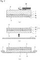
Figs. 1(a) to 1(c) are schematic cross-sectional views illustrating steps to laminating a surface protective tape onto a semiconductor wafer in the first embodiment of the present invention. FragmentaryFig. 1 (a) shows a semiconductor wafer. FragmentaryFig. 1 (b) shows how the mask-integrated surface protective tape is laminated. FragmentaryFig. 1(c) shows a semiconductor wafer on which the mask-integrated surface protective tape is laminated. - {
Figs. 2(a) to 2(c) }
Figs. 2(a) to 2(c) are schematic cross-sectional views illustrating steps to thinning and fixing of the semiconductor wafer in the first embodiment of the present invention. FragmentaryFig. 2(a) shows thinning step of the semiconductor wafer. FragmentaryFig. 2(b) shows how a wafer-fixing tape is laminated. FragmentaryFig. 2(c) shows a state in which the semiconductor wafer is fixed to a ring flame. - {
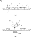
Figs. 3(a) to 3(c) }
Figs. 3(a) to 3(c) are schematic cross-sectional views illustrating steps to the mask formation in the first embodiment of the present invention. FragmentaryFig. 3(a) shows how the surface protective tape is peeled off from the mask-integrated surface protective tape while leaving the mask material layer. FragmentaryFig. 3(b) shows a state in which the mask material layer of the mask-integrated surface protective tape is exposed (uncovered). FragmentaryFig. 3(c) shows a step of cutting off the mask material layer corresponding to the street with a laser. - {
Figs. 4(a) to 4(c) }
Figs. 4(a) to 4(c) are schematic cross-sectional views illustrating the plasma dicing and plasma ashing steps in the first embodiment of the present invention. FragmentaryFig. 4(a) shows how the plasma dicing is carried out. FragmentaryFig. 4(b) shows a state in which the semiconductor wafer is singulated into chips. FragmentaryFig. 4(c) shows how the plasma ashing is carried out. - {
Figs. 5(a) and 5(b) }
Figs. 5(a) and 5(b) are schematic cross-sectional views illustrating steps to picking up a chip in the first embodiment of the present invention. FragmentaryFig. 5(a) shows a state, in which the mask material layer is removed. FragmentaryFig. 5(b) shows how the chip is picked up. - {
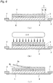
Figs. 6(a) to 6(c) }
Figs. 6(a) to 6(c) are schematic cross-sectional views illustrating a state before and after a treatment with an ultraviolet irradiation carrying out in the second embodiment of the present invention. FragmentaryFig. 6(a) shows a state in which both sides of the front and the back of the semiconductor wafer are covered and fixed with the mask-integrated surface protective tape and the wafer-fixing tape, respectively. FragmentaryFig. 6(b) shows how an ultraviolet light is irradiated. FragmentaryFig. 6(c) shows how the surface protective tape is peeled off from the mask-integrated surface protective tape while leaving the mask material layer. - The method of producing the semiconductor chip of the present invention (hereinafter, referred to simply as the production method of the present invention) is a method of obtaining a semiconductor chip by the plasma dicing. As described below, the production method of the present invention does not need a photolithography process, and allows a significant suppression of production costs of the semiconductor chips or semiconductor products.
- The method of producing the present invention includes, at least, the following steps (a) to (d):
- (a) a step of, in the state of having laminated a mask-integrated surface protective tape containing a substrate film, a temporary-adhesive layer provided on the substrate film, and a mask material layer provided on the temporary-adhesive layer, on the side of a patterned surface of a semiconductor wafer, grinding the backing-face of the semiconductor wafer; laminating a wafer fixing tape on the backing-face side of the ground semiconductor wafer; and supporting and fixing the wafer to a ring flame;
- (b) a step of, after integrally peeling both the substrate film and the temporary-adhesive layer from the mask-integrated surface protective tape (in other words, after peeling a surface protective tape from the mask-integrated surface protective tape) thereby to expose the mask material layer on top, forming an opening by cutting a portion of the mask material layer corresponding to a street of the semiconductor wafer with a laser;
- (c) a plasma dicing step of segmentalizing the semiconductor wafer on the street by a plasma irradiation to singulate it into semiconductor chips; and
- (d) an ashing step of removing the mask material layer by the plasma irradiation.
- In the present invention, the following step (e), after the step (d), is preferably included. In the present invention, when the production method includes following step (e), the following step (f) is preferably included after the step (e).
- (e) A step of picking up the semiconductor chip from the wafer-fixing tape,
- (f) A step of transiting the picked-up semiconductor chip to a die bonding step.
- The mask-integrated surface protective tape used in the present invention has a substrate film, a temporary-adhesive layer provided on the substrate film, and a mask material layer provided on the temporary-adhesive layer. In the present specification, a laminated body containing a substrate film and a temporary-adhesive layer provided on this substrate film is sometimes called as "a surface protective tape". In other words, the mask-integrated surface protective tape used in the present invention is a tape having a laminated structure in which the mask material layer has been further provided on the temporary-adhesive layer of the surface protective tape. In the mask-integrated surface protective tape used in the present invention, the substrate film, the temporary-adhesive layer and the mask material layer may have each independently a single layer structure or a plural layer structure containing two or more layers. The temporary-adhesive layer and the mask material layer each have preferably a single layer structure.
- In the mask-integrated surface protective tape used in the present invention, at least the temporary-adhesive layer is preferably radiation-curable (in other words, has a radiation-curing property), and it is more preferable that only the temporary-adhesive layer is radiation-curable. Further, it is preferable that the mask material layer is pressure-sensitive.
- In a case where the temporary-adhesive layer is radiation-curable, in the above-described step (b), it is preferable to contain a step of curing the temporary-adhesive layer by irradiating a radiation thereto, before integrally peeling both the above-described substrate film and the above-described temporary-adhesive layer from the above-described mask-integrated surface protective tape thereby to expose the mask material layer on top. By curing the temporary-adhesive layer, an interlayer-peeling property between the mask material layer and the temporary-adhesive layer is improved, so that the peeling of the surface protective tape from the mask-integrated surface protective tape becomes easy.
- Preferable embodiments of the production method of the present invention are described below with reference to the drawings. However, the present invention is not limited to the following embodiments, except for the requirements defined by the present invention. Further, the form shown in each drawing is a schematic view for facilitating the understanding of the present invention. Therefore, regarding the size, the thickness, the relative magnitude relation and the like of each component, the large one or the small one is sometimes changed for the purpose of illustration, and the form does not show a real relation as it is. Further, the present invention is not limited to outer forms and shapes shown in these figures, except for the requirements defined by the present invention.
- Preferable embodiments of the method of producing the semiconductor chip of the present invention may be classified into first and second embodiments, as described below.
- Note that, as the apparatus, the materials and the like used in the following embodiments, an ordinary apparatus, materials and the like which have been conventionally used in the processing of the semiconductor wafer may be used, unless otherwise indicated, and the conditions of use for them can be appropriately set and optimized in accordance with the intended use within a range of an ordinary method for using. Further, omitted are duplicated descriptions about the materials, structures, methods, effects, and the like, which are common to each embodiment.
- The first embodiment of a production method of the present invention is described with reference to
Fig. 1 to Fig. 5 . - A
semiconductor wafer 1 has a patternedface 2 on the surface S of which a circuit or the like of the semiconductor device is formed (seeFig. 1(a) ). On thispatterned surface 2, a mask-integrated surfaceprotective tape 3 in which amask material layer 3b has been further provided on a temporary-adhesive layer 3ab of a surfaceprotective tape 3a in which the temporary-adhesive layer 3ab has been provided on a substrate film 3aa, is laminated (seeFig. 1 (b) ), whereby asemiconductor wafer 1 whosepatterned surface 2 is covered with the mask-integrated surfaceprotective tape 3 is obtained (seeFig. 1 (c) ). - Then, the backing-face B of the
semiconductor wafer 1 is ground by a wafer-grinding apparatus M1, to thin a thickness of the semiconductor wafer 1 (seeFig. 2(a) ). On the ground backing-face B, a wafer-fixingtape 4 is laminated (seeFig. 2(b) ), to support and fix the wafer to a ring flame F (seeFig. 2(c) ). - The surface
protective tape 3a of the mask-integrated surfaceprotective tape 3 is peeled off from thesemiconductor wafer 1, while leaving themask material layer 3b on the semiconductor wafer 1 (seeFig. 3(a) ), so that themask material layer 3b is exposed (uncovered) (seeFig. 3(b) ). Further, CO2 laser L is irradiated from the surface S side toward a plurality of streets (not shown) appropriately formed in a grid pattern or the like onto the patternedface 2, thereby to remove a portion corresponding to a street of themask material layer 3b, so that streets of the semiconductor wafer are opened (seeFig. 3(c) ). - Then, a treatment with the plasma P1 of SF6 gas is carried out from the surface S side, thereby to etch the
semiconductor wafer 1 which is exposed at the street portion (seeFig. 4(a) ), and the semiconductor wafer is divided intoindividual chips 7, which results in singulation (seeFig. 4(b) ). After that, ashing with the plasma P2 of O2 gas is carried out (seeFig. 4(c) ), thereby to remove themask material layer 3b remaining on the surface S (seeFig. 5(a) ). Then, at last, thesingulated chip 7 is knocked up by a pin M2, and is picked up by adsorption with a collet M3 (seeFig. 5(b) ). - Herein, a process of etching of Si of the semiconductor wafer with the use of SF6 gas is also called as a BOSCH process. This process allows a reaction of the exposed Si and a fluorine atom formed from a plasmarized SF6, thereby to remove the exposed Si as silicon tetrafluoride (SiF4), which is also called as reactive ion etching (RIE). On the other hand, the removal with the O2 plasma is a method which is also used as plasma cleaner in the course of a semiconductor production process, and is also called as ashing (ash-making), which is one of means for removal of the organic substance. This method is carried out, in order to clean an organic substance residue remaining on a semiconductor device surface.
- Next, before describing a second embodiment, the materials used in the production method of the present invention are described. These materials may be also preferably used in the second embodiment described below.
- The
semiconductor wafer 1 is a silicon wafer, on its one side, having the patternedface 2 on which the circuit or the like of the semiconductor device is formed. Thepatterned face 2 is a face on which the circuit or the like of the semiconductor device is formed, which has a street in a planar view. - The mask-integrated surface
protective tape 3 contains the temporary-adhesive layer 3ab provided on the substrate film 3aa, and further the mask material layer provided on the temporary-adhesive layer 3ab, and has a function to protect the semiconductor device formed on the patternedface 2. Specifically, at the wafer-thinning step which is a post-step, thesemiconductor wafer 1 is supported by the patternedface 2, and the backing-face of the wafer is ground. Therefore, the mask-integrated surfaceprotective tape 3 needs to withstand a load in grinding. For this reason, the mask-integrated surfaceprotective tape 3 is different from a mere resist film or the like, and has: the thickness enough to coat the device formed on the patterned face; and the pressing resistance which is low, and has: a high adhesiveness that can adhere tightly to the device, so that the infiltration of dusts, grinding water, and the like, in grinding, is not occurred. - Out of the mask-integrated surface
protective tape 3, the substrate film 3aa is composed of a plastic, a gum, or the like, and examples of its materials include: a homopolymer or copolymer of α-olefin, such as polyethylene, polypropylene, ethylene/propylene copolymer, polybutene-1, poly-4-methylpentene-1, ethylene/vinyl acetate copolymer, ethylene/acrylic acid copolymer, and ionomers, or a mixture thereof; an elemental substance or a mixture of 2 or more kinds, such as polyethylene terephthalate, polyethylene naphthalate, polyphenylene sulfide, polyether imide, polyimide, polycarbonate, polymethyl methacrylate, polyurethane, and styrene/ethylene/butene- or pentene-based copolymer; and a resin composition in which another resin, a filler, an additive or the like is blended with any of the foregoing polymers. These can be appropriately selected depending on the required characteristics. A laminate of a low-density polyethylene and an ethylene/vinyl acetate copolymer, a laminate of a polypropylene and a polyethylene terephthalate, a polyethylene terephthalate, or a polyethylene naphthalate is one of preferable materials. - The foregoing substrate film 3aa can be produced using a general extrusion method. In the case where the substrate film 3aa is obtained by laminating various resins, these are produced by a co-extrusion method, a lamination method, or the like. At this time, as conventionally practiced in the ordinary production method of the laminate film, an adhesion layer may be provided between resins. A thickness of the substrate film 3aa is preferably from 20 to 200 µm, from the viewpoint of strength and elongation property and the like, and radiation permeation property.
- The temporary-adhesive layer 3ab takes a role in protection of the patterned surface together with a mask material by covering an asperity of the device formed on the patterned surface to enhance adhesion property to the patterned surface. In order to make the mask-integrated surface protective tape withstand a load of the wafer-thinning step (backgrinding step), it is preferable that the adhesion property of the temporary-adhesive layer 3ab to a
mask material layer 3b or a substrate film 3aa in the wafer-thinning step is high. On the other hand, after the wafer-thinning step, because the temporary-adhesive layer is integrally peeled with the substrate film 3aa from the mask material layer, it is preferable that the adhesion property of the temporary-adhesive layer to the mask material layer is low (high peeling property is preferable). In order to achieve these properties in higher level, it is preferable to adopt a radiation-curable temporary-adhesive in the temporary-adhesive layer 3ab. By rendering the temporary-adhesive layer 3ab radiation-curable, the temporary-adhesive layer becomes 3-dimentionally reticulated by radiation irradiation, which results in reduction of the adhesive force. For this reason, by radiation irradiation after the wafer-thinning step, a rigid adhesion to the mask material layer is released and resultantly the temporary-adhesive layer can be simply peeled from the mask material layer (such specific embodiments are described below). In a case of rendering the temporary-adhesive layer 3ab radiation-curable, the production method of the present invention is preferably carried out in accordance with a second embodiment described below. Note that the temporary-adhesive for the temporary-adhesive layer 3ab in the present invention is not limited to a radiation-curable temporary-adhesive, but also a non-radiation curable temporary-adhesive (pressure-sensitive temporary-adhesive) may be used in a range of providing a desired property. In this case, the production method of the present invention is preferably carried out in accordance with the above-described first embodiment. - In the present specification, the term "radiation" is a concept including both a light beam such as ultraviolet, and an ionizing radiation such as an electron beam. The radiation for use of the present invention is preferably ultraviolet.
- In a case where the temporary-adhesive layer 3ab is composed of a radiation-curable temporary-adhesive, a temporary-adhesive containing an acrylic temporary-adhesive and a radiation-polymerizable compound may be preferably used.
- The acrylic temporary-adhesive is a (meth)acrylic copolymer, or a mixture of a (meth)acrylic copolymer and a curing agent. Examples of the (meth)acrylic copolymer include a copolymer having a (meth)acrylic acid ester as a structural component, or a mixture of 2 or more copolymers having a (meth)acrylic acid ester as a structural component. The mass-average molecular weight of these copolymers is normally about 300,000 to 1,000,000. A proportion of the (meth)acrylic acid ester component of the total monomer component of the (meth)acrylic copolymer is preferably 70% or more, more preferably 80% or more, and further more preferably 90% or more. Further, in a case where the proportion of the (meth)acrylic acid ester component of the total monomer component of the (meth)acrylic copolymer is not 100% by mole, it is preferable that the remaining monomer component is a monomer component (constituent and the like derived from (meth)acrylic acid) existing in the form of (meth)acryloyl group polymerized as a polymerizable group. Further, the proportion of the (meth)acrylic acid ester component having a functional group (for example, hydroxyl group) reacting with a curing agent described below, of the total monomer component of the (meth)acrylic copolymer is preferably 1% by mole or more, more preferably 2% by mole or more, further more preferably 5% by mole or more, and still further more preferably 10% by mole or more. A proportion of the (meth)acrylic acid ester component is preferably 35% by mole or less, more preferably 25% by mole or less. In addition, the proportion of structural component (monomer component), which has a functional group (for example, hydroxyl group) reacting with a curing agent described below, of the total monomer component of the (meth)acrylic copolymer is preferably 5% by mole or more, more preferably 10% by mole or more. The upper limit is preferably 35% by mole or less, more preferably 25% by mole or less.
- The above-described (meth)acrylic acid ester component is preferably a (meth)acrylic acid alkyl ester (also referred to as alkyl (meth)acrylate). The number of carbon atoms of the alkyl group which constitutes the (meth)acrylic acid alkyl ester is preferably from 1 to 20, more preferably from 1 to 15, and further more preferably from 1 to 12.
- The curing agent is used for adjusting an adhesion force and a cohesion force, by conducting reaction of it with a functional group of the (meth)acrylic copolymer. Examples of the curing agent include: an epoxy compound having 2 or more epoxy groups in the molecule, such as 1,3-bis(N,N-diglycidyl aminomethyl)cyclohexane, 1,3-bis(N,N-diglycidyl aminomethyl)toluene, 1,3-bis(N,N-diglycidyl aminomethyl)benzene, or N,N,N',N'-tetraglycidyl-m-xylenediamine; an isocyanate-based compound having 2 or more isocyanate groups in the molecule, such as 2,4-tolylenediisocyanate, 2,6-tolylenediisocyanate, 1,3-xylylenediisocyanate, 1,4-xylylenediisocyanate, or diphenylmethane-4,4'-diisocyanate; an aziridine-based compound having 2 or more aziridinyl groups in the molecule, such as tetramethylol-tri-β-aziridinyl propionate, trimethylol-tri-p-aziridinyl propionate, trimethylolpropane-tri-β-aziridinyl propionate, or trimethylolpropane-tri-β-(2-methylaziridine)propionate; and the like. An addition amount of the curing agent may be adjusted depending on a desired adhesion force, and is suitably from 0.1 to 5.0 mass parts with respect to 100 mass parts of the (meth)acrylic copolymer. In the temporary-adhesive layer of the mask-integrated surface protective tape used in the present invention, the curing agent is in a state of having reacted with the (meth)acrylic copolymer.
- As for the radiation-polymerizable compound described above, a low-molecular weight compounds having, in the molecule, at least two or more photopolymerizable carbon-carbon double bonds which can be three-dimensionally reticulated by radiation irradiation are widely used. Specifically, use may be widely applicable of: trimethylolpropane triacrylate, tetramethylolmethane tetraacrylate, pentaerythritol triacrylate, pentaerythritol tetraacrylate, dipentaerythritol mono-hydroxypentaacrylate, dipentaerythritol hexaacrylate, 1,4-butyleneglycol diacrylate, 1,6-hexanediol diacrylate, polyethyleneglycol diacrylate, and acrylate-based compounds such as oligoester acrylates.
- Further, in addition to the acrylate-based compounds, use can be also made of a urethane acrylate-based oligomer. The urethane acrylate-based oligomer is obtained by conducting reaction of an acrylate or methacrylate having a hydroxy group (for example, 2-hydroxyethyl acrylate, 2-hydroxyethyl methacrylate, 2-hydroxypropyl acrylate, 2-hydroxypropyl methacrylate, polyethyleneglycol acrylate, polyethyleneglycol methacrylate, and the like) with a urethane prepolymer having an isocyanate group at the end thereof, which is obtained by conducting reaction of a polyol compound, such as a polyester type- or a polyether type-polyol, and a polyvalent isocyanate compound (for example, 2,4-tolylene diisocyanate, 2,6-tolylene diisocyanate, 1,3-xylylene diisocyanate, 1,4-xylylene diisocyanate, diphenyl methane-4,4'-diisocyanate, and the like).
- As a blending ratio of the acrylic temporary-adhesive and the radiation-polymerizable compound in the radiation-curable temporary-adhesive, the radiation-polymerizable compound is desirably blended in the range of 50 to 200 mass parts and preferably 50 to 150 mass parts with respect to 100 mass parts of the acrylic temporary-adhesive. If the blending ratio is in this range, it is possible to decline sharply the adhesion force of the temporary-adhesive layer after radiation irradiation.
- Further, as the radiation-curable temporary-adhesive used in the temporary-adhesive layer 3ab, it is also preferable to use a radiation-polymerizable (meth)acrylic copolymer in which the above-described (meth)acrylic copolymer itself has been rendered radiation-polymerizable. In this case, the radiation-curable temporary-adhesive may contain a curing agent.
- The radiation-polymerizable (meth)acrylic copolymer is a copolymer having, in the molecule of the copolymer, a reactive group which is capable of realizing a polymerization reaction upon exposure to a radiation, particularly to an ultraviolet. As the reactive group, an ethylenically unsaturated group, in other words, a group having a carbon-carbon double bond, is preferred. Examples thereof include: a vinyl group, an allyl group, a styryl group, a (meth)acryloyloxy group, a (meth)acryloylamino group, and the like.
- The introduction of the above-described reactive group to the copolymer may be performed, for example, by reacting a copolymer having a hydroxyl group with a compound having both a group (for example, isocyanate group) reacting with the hydroxyl group and the above-described reactive group [representatively 2-(meth)acryloyloxyethyl isocyanate].
- Further, the proportion of the monomer component having the above-described reactive group of the total monomer component which constitutes the above-described radiation-polymerizable (meth)acrylic copolymer is preferably from 2 to 40% by mole, more preferably from 5 to 30% by mole, and further more preferably from 10 to 30% by mole.
- Further, in the case of conducting polymerization and curing of a temporary-adhesive layer 3ab by radiation, a photopolymerization initiator, for example, isopropylbenzoin ether, isobutylbenzoin ether, benzophenone, Michler's ketone, chlorothioxanthone, benzyl methyl ketal, α-hydroxycyclohexyl phenyl ketone, 2-hydroxymethylphenyl propane, and the like can be used. By adding at least one of these compounds to the temporary-adhesive layer, a polymerization reaction can be efficiently accelerated.
- The temporary-adhesive layer 3ab may further contain a photosensitizer, any of known tackifier, softener, antioxidant, or the like.
- As for the temporary-adhesive layer 3ab, those embodiments described at paragraphs [0036] to [0055] of
JP-A-2014-192204 - The thickness of the temporary-adhesive layer 3ab is preferably from 5 to 100 µm, more preferably from 10 to 100 µm, and further more preferably from 2 to 50 µm, from the viewpoint of more increasing protective ability to the device and the like formed on the patterned
surface 2, and more increasing adhesion to the patterned surface, and also more increasing removal ability by an ashing treatment. In this regard, depending on the variety of the device, an asperity of the patterned surface is approximately about a few micrometers to about 15 µm, and therefore the thickness of the temporary-adhesive layer 3ab is preferably from 5 to 30 µm. - In the
mask material layer 3b, a non-radiation curable, so-called pressure-sensitive temporary-adhesive is preferably used. As this pressure-sensitive temporary-adhesive, a mixture of the above-described (meth)acrylic copolymer and a curing agent may be preferably used. - Further, it is also preferable that the mask material layer has an etching rate property described below. In this case, it is also preferable to use a radiation-curable temporary-adhesive in the
mask material layer 3b. - The thickness of the
mask material layer 3b is preferably from 1 to 50 µm and more preferably from 5 to 20 µm, from the viewpoint of a following capability to the patterned surface and a removing ability by plasma. - The wafer-fixing
tape 4 is required to hold thesemiconductor wafer 1 and to have resistance to plasma which is sustainable even if the wafer-fixing tape is subjected to the plasma dicing step. Further, in the picking-up step, a good picking-up property and also an expansion property and the like in some cases are required. As the foregoing wafer-fixingtape 4, a tape similar to the surfaceprotective tape 3a may be used. Further, use may be made of any of known dicing tapes used in a conventional plasma dicing method, which are generally called as a dicing tape. Further, the use can be also made of a dicing die-bonding tape, in which an adhesion bond for die-bonding is laminated between the temporary-adhesive layer and the substrate film, in order to make it easy to transit to the dicing die-bonding step after picking-up. - For the laser irradiation with which the
mask material layer 3b is cut, use can be made of a laser irradiator for irradiating an ultraviolet or infrared laser light. In this laser irradiator, a laser irradiation part capable of freely moving along the street of thesemiconductor wafer 1 is arranged. Laser can be irradiated, which is provided with an output controlled suitably to remove themask material layer 3b. In particular, if CO2 laser is used as a laser light, it is possible to obtain a large power of several to tens of watts. CO2 laser can be preferably used for the present invention. - In order to carry out the plasma dicing and the plasma ashing, use can be made of a plasma-etching apparatus. The plasma-etching apparatus is an apparatus, which is capable of subjecting the
semiconductor wafer 1 to dry etching, and in which a sealed treatment space is made in a vacuum chamber, to place thesemiconductor wafer 1 on the side of the electrode for a high-frequency wave. A gas for plasma generation is supplied from the side of a gas-supplying electrode provided facing the electrode for high-frequency wave. If a high-frequency voltage is applied to the electrode for a high-frequency wave, plasma is generated between the gas-supplying electrode and the electrode for a high-frequency wave. Therefore, the resultant plasma is used. By circulating a refrigerant in a heat-producing electrode for high-frequency wave, it is possible to prevent a temperature elevation of thesemiconductor wafer 1 due to the heat of this plasma. - In accordance with the method of producing the semiconductor chip (the method of processing the semiconductor wafer), any photolithographic step or the like becomes unnecessary, which is provided with a resist to be used in the conventional plasma dicing process, by giving a mask function in the plasma dicing to the surface protective tape protecting the patterned face. In particular, by using the surface protective tape, a technique becomes unnecessary, in which a high level of alignment, such as printing and transferring, is required for the mask formation. The surface protective tape can be easily laminated on the semiconductor wafer surface, and a mask can be easily formed by the laser equipment.
- Further, the
mask material layer 3b can be removed with O2 plasma, and therefore removal of the mask portion can be carried out by the same apparatus as the plasma dicing apparatus. In addition, the plasma dicing is carried out from the patternedface 2 side (surface S side), and therefore it is not necessary to turn the chip upside down before the picking-up operation. From these reasons, the facilities can be simplified, and process costs can be considerably suppressed. - The second embodiment is different from the first embodiment in the point that the second embodiment contains a step of curing the temporary-adhesive layer by irradiating the mask-integrated surface
protective tape 3 with a radiation, such as an ultraviolet light or the like, prior to the step of peeling-off the surfaceprotective tape 3a in the first embodiment. Other steps are the same as in the first embodiment. - Specifically, the mask-integrated surface
protective tape 3 is laminated on the surface S side of thesemiconductor wafer 1, and the wafer-fixingtape 4 is laminated on the ground backing-face B side of thesemiconductor wafer 1, followed by supporting and fixing the wafer to a ring flame F (seeFig. 2(c) ,Fig. 6(a) ). Then, an ultraviolet light (UV) is irradiated from the surface S side toward the mask-integrated surface protective tape 3 (seeFig. 6(b) ). Then, after curing the temporary-adhesive layer 3ab of the mask-integrated surfaceprotective tape 3, the surfaceprotective tape 3a is removed (seeFig. 6(c) ), whereby themask material layer 3b is uncovered. Then, this step is transited to a step of cutting, with a laser L, a portion of themask material layer 3b corresponding to the street. - In the mask-integrated surface protective tape that can be used in the second embodiment, at variation with the mask-integrated surface
protective tape 3 described in the first embodiment, a material which is capable of being cured with a radiation, such as an ultraviolet ray or the like, is used in the temporary-adhesive layer 3ab. - By curing the temporary-adhesive layer 3ab with the ultraviolet light or the like, peeling-off of the surface
protective tape 3a frommask material layer 3b is made easily performed. - Subsequently an embodiment of a preferable mask-integrated surface protective tape used in the production method of the present invention (herein, also referred to as "a mask-integrated surface protective tape of the present invention") is described below in more details. However, the mask-integrated surface protective tape used in the production method of the present invention is not limited to the following embodiments, but mask-integrated surface protective tapes in the form described above may be widely used.
- The mask-integrated surface
protective tape 3 of the present invention is a tape in which amask material layer 3b is further formed on a temporary-adhesive layer 3ab of the surfaceprotective tape 3a in which the temporary-adhesive layer 3ab has been formed on a substrate film 3aa, and in which an etching rate (EF) of the above-describedmask material layer 3b by a SF6 plasma is lower than an etching rate (EO2) by an O2 plasma. - In the mask-integrated surface protective tape of the present invention, the substrate film, the temporary-adhesive layer and the mask material layer each may have a single layer structure or a plural layer structure containing 2 layers or more. The temporary-adhesive layer and the mask material layer each have preferably a single layer structure. In the mask-integrated surface protective tape of the present invention, the forms described in the above-described production method of the present invention may be preferably used in the constitution of the substrate film and the temporary-adhesive layer. The constitution of the mask material layer of the mask-integrated surface protective tape of the present invention is described below.
- In the mask-integrated surface protective tape of the present invention, the
mask material layer 3b scarcely damages to a semiconductor device or the like when adhered to apatterned surface 2, and scarcely causes a breakage of the semiconductor device or the like and an adhesive residue on the surface at the time of removal. Further, in the present invention, because themask material layer 3b has such characteristics that an etching rate (EF) by a SF6 plasma is lower than an etching rate (EO2) by an O2 plasma, the mask formed on the circuit surface has a plasma resistance which acts as a mask at the time of plasma dicing, and the formed mask can be more certainly removed by ashing. - As for the mask-integrated surface protective tape of the present invention, the etching rate (EF) of the mask material layer by the SF6 plasma means an etching rate of the mask material layer under the condition of etching a Si wafer at the etching rate of 15 µm/min by the SF6 gas plasma, as described in Example.
- Further, in the mask-integrated surface protective tape of the present invention, the etching rate (EO2) of the mask material layer by an O2 plasma means an etching rate of the mask material layer under the conditions of etching a mask material layer a at the etching rate of 1 µm/min by the O2 gas plasma, as described in Example.
- Further, in the mask-integrated surface protective tape of the present invention, EO2/EF, which is a ratio of an etching rate (EO2) by an O2 plasma to an etching rate (EF) by a SF6 plasma, is preferably 2.0 or more, more preferably 4.0 or more, and further more preferably 6.0 or more. The upper limit thereof is not particularly limited, but is 8.0 or less in practice.
- Note that, in a case where the mask material layer is composed of a radiation-polymerizable mask material, the above-described etching rate means an etching rate of the mask material layer after it has been subjected to a radiation polymerization.
- Further, in the mask-integrated surface protective tape of the present invention, it is preferable that the light transmittance at the wavelength of 10 µm (hereinafter, also referred to as a light transmittance10 µm) of the
mask material layer 3b is 80% or less and the visible light transmittance at the wavelength of 350 to 700 nm (hereinafter, also referred to as a visible light transmittance350-700 nm) is 50% or more. - The light transmittance10 µm is more preferably 79% or less and further more preferably 75% or less. The lower limit thereof is not particularly limited, but is 30% or more in practice.
- The visible light transmittance350-700 nm is more preferably 70% or more, further preferably 90% or more. The upper limit thereof is not particularly limited, but is preferably 100% or less.
- Under the conditions that the light transmittance10 µm is within the above-described preferable range, a portion of the mask material layer corresponding to a street of the semiconductor wafer can be efficiently cut by a CO2 laser.
- Further, under the conditions that the visible light transmittance350-700 nm is within the above-described preferable range, the
patterned surface 2 of the semiconductor wafer can be properly recognized and a recognition error at the time of opening on the street can be prevented. - The above-described light transmittance is measured in accordance with the method described in Example below.
- Further, the mask-integrated surface
protective tape 3 of the present invention has a function of protecting apatterned surface 2. Specifically, in the wafer-thinning step which is a post step, while thesemiconductor wafer 1 is supported at thepatterned surface 2 thereof, the backing-face of the wafer is ground, and therefore it is necessary to withstand a grinding load. For this reason, the mask-integrated surfaceprotective tape 3 of the present invention is different from a simple resist film, or the like, and has a thickness enough to coat a device formed on the patterned surface, and has a low pressure resistance, and has a high adhesion property enough to closely adhere to the device in order to avoid entrance of a grinding dust, a grinding water and the like. - In the mask-integrated surface protective tape of the present invention, a variety of performances as described above is required for the
mask material layer 3b, and therefore a non-curable mask material having the foregoing properties may be used. Further, a use can be made of a radiation-polymerizable mask material such as an ultraviolet-curable mask material and an ionizable radiation-curable mask material like an electron beam-curable mask material and the like whereby the mask material is 3-dimentionally reticulated by preferably radiation and more preferably ultraviolet irradiation, and a residue of the mask material layer is less likely to be occurred by ashing. - As such mask materials, an acrylic temporary-adhesive and a mask material containing this acrylic temporary-adhesive and a radiation-polymerizable compound may be preferably used.
- The above-described acrylic temporary-adhesive is a (meth)acrylic copolymer, or a mixture of a (meth)acrylic copolymer and a curing agent, and acrylic temporary-adhesives described in the foregoing temporary-adhesive layer may be preferably used.
- In this regard, from the viewpoint of adhesion property, a proportion of the (meth)acrylic acid ester having a functional group (for example, hydroxyl group) which reacts with a curing agent, of the total monomer component of the (meth)acrylic copolymer, is preferably 0.1% by mole or more, and more preferably 0.5% by mole or more. The upper limit thereof is preferably 20% by mole or less, and more preferably 15% by mole or less. The mass-average molecular weight of the (meth)acrylic copolymer is preferably from about 100,000 to about 1,000,000.
- In the mask-integrated surface protective tape of the present invention, for the
mask material layer 3b, a radiation-curable temporary-adhesive which is cured by a radiation or a pressure-sensitive temporary-adhesive which is not cured by a radiation may be preferably used. - As the above-described radiation-curable temporary-adhesive, a temporary-adhesive containing the above-described acrylic temporary-adhesive and an acrylate compound having 1 or 2 photo-polymerizable carbon-carbon double bonds in the molecule is preferably used. In the above-described radiation-curable temporary-adhesive, the content of the acrylate compound having 1 or 2 photo-polymerizable carbon-carbon double bonds in the molecule is preferably 15% by mass or more, more preferably from 15 to 70% by mass, and further more preferably from 15 to 65% by mass. Further, the acrylate compound having 1 or 2 photo-polymerizable carbon-carbon double bonds in the molecule is preferably an acrylate compound having 1 photo-polymerizable carbon-carbon double bond in the molecule.
- As the above-described acrylate compound having 1 or 2 photo-polymerizable carbon-carbon double bonds in the molecule, specifically, it is possible to use widely and preferably 2-hydroxy-3-phenoxypropyl acrylate, 1,4-butylene glycol diacrylate, 1,6-hexanediol acrylate, polyethylene glycol diacrylate and the like.
- Further, a urethane acrylate oligomer having 1 or 2 photo-polymerizable carbon-carbon double bonds in the molecule can be preferably used, and the urethane acrylate oligomer obtained by a method described in the foregoing section of the temporary-adhesive layer can be preferably used.
- As a blend ratio of an acrylic temporary-adhesive and an acrylate compound having 1 or 2 photo-polymerizable carbon-carbon double bonds in the molecule in the above-described radiation-curable temporary-adhesive, the acrylate compound having 1 or 2 photo-polymerizable carbon-carbon double bonds in the molecule is blended in the range of preferably 10 to 250 parts by mass and more preferably 15 to 200 parts by mass, with respect to 100 parts by mass of the acrylic temporary-adhesive. When the blend ratio is not more than the above-described upper limit, breakage of the wafer can be prevented effectively without an excessive deformation of the mask material layer at the time of backgrinding.
- Further, in the mask-integrated surface protective tape of the present invention, for the mask material layer, a radiation-polymerizable (meth)acrylic acid ester in the foregoing temporary-adhesive layer, a photo-polymerization initiator, and other inclusion components (photosensitizer, conventionally known tackifier, softener, antioxidant, and the like) may be preferably used.
- In the mask-integrated surface protective tape of the present invention, the thickness of the
mask material layer 3b is preferably 5 to 100 µm, and more preferably 5 to 30 µm, from the viewpoint of more increasing a protection ability of a device or the like formed on the patternedsurface 2, and also more increasing adhesion property to the patterned surface, whereby the entrance of SF6 gas is prevented, and a removing property due to an ashing treatment is increased. Note that, depending on the variety of the devices, the asperity of the patterned surface thereof is approximately from about a few micrometers to about 15 µm, and therefore the thickness of themask material layer 3b is more preferably 5 to 30 µm. - Each of the above-described embodiments is an example of the present invention and therefore the present invention is not limited to these embodiments. Accordingly, addition, deletion, modification and the like of a known process may be made in each process to the extent of no departure from the scope of the present invention.
- The present invention will be described in more detail based on examples given below, but the invention is not meant to be limited by this.
- With an acrylic polymer (random polymer) composed of constituents originated from each monomer of 80 mol% of 2-ethylhexyl acrylate, 1 mol% of methyl acrylate and 19 mol% of 2-hydroxyethyl acrylate, 2-isocyanatoethyl methacrylate having an ethylenical unsaturated bond (photo-reactive group) and an isocyanate group in the molecule (MOI, manufactured by Showa Denko K.K.) was reacted, to obtain an acrylic polymer A1 (Mw: 800,000, acid value: 12 mg KOH/g, hydroxyl value: 43 mg KOH/g, double bond equivalent: 0.9 eq) having an ethylenical unsaturated bond in the molecule.
- A temporary-adhesive composition A was obtained by blending 2.0 parts by mass of an isocyanate curing agent (trade name: L-45, manufactured by Tosoh Corporation) and 5.0 parts by mass of a photo-polymerization initiator (trade name: ESACURE KIP 100F, manufactured by Lamberti) with respect to 100 mass parts of the acrylic polymer A1.
- A film formation was carried out by an extrusion method so as to be a film thickness of 110 µm using a LDPE (low density polyethylene) resin (NIPOLONHARD 205, manufactured by Tosoh Corporation) and EVA (ethylene-vinyl acetate copolymer) resin (ULTRATHENE 540, manufactured by Tosoh Corporation) to prepare a substrate film 3aa having a 2-layered structure.
- A surface
protective tape 3a was obtained by coating and drying the above-described temporary-adhesive composition A on a release film, and then laminating and transferring the formed temporary-adhesive layer on an EVA layer of the above-described substrate film 3aa to form a radiation-curable temporary-adhesive layer 3ab having a thickness of 20 µm. - With respect to 100 parts by mass of an acrylic polymer A2 (random polymer, Mw: 1,000,000, acid value: 23 mg KOH/g, hydroxyl value: 0 mg KOH/g) composed of constituents originated from each monomer of 95 mol% of butyl acrylate and 5 mol% of methyl acrylate, 2.0 parts by mass of an epoxy curing agent (TETRAD-C, manufactured by Mitsubishi Gas Chemical Company, Inc.) was blended, to obtain a mask material composition A. A mask-integrated surface
protective tape 3 was obtained by forming a film on the side of the temporary-adhesive layer 3ab of the above-described surfaceprotective tape 3a using this mask material composition A so as to be a dried film thickness of 10 µm thereby to form amask material layer 3b which is a pressure-sensitive temporary-adhesive layer. - The obtained mask-integrated surface
protective tape 3 was laminated on a silicon wafer (diameter: 8 inches) using a tape laminator (trade name: DR-3000II, manufactured by Nitto Seiki Co., Ltd.). The wafer laminated with the mask-integrated surfaceprotective tape 3 was ground until the thickness of 50 µm using a backgrinding apparatus (trade name: DGP8760, manufactured by Disco Corporation). The presence or absence of the crack in the wafer at that time was determined visually and also by using a microscope. - An UV-curable wafer fixing tape 4 (trade name: UC-353EP-110, manufactured by Furukawa Electric Co., Ltd.) was laminated on the ground wafer backing-face side, followed by supporting and fixing by using the ring flame. Next, an ultraviolet light was irradiated from the side of the mask-integrated surface
protective tape 3, and then the surfaceprotective tape 3a was peeled off, leaving themask material layer 3b. And by irradiating with the CO2 laser along the street portion of the silicon wafer from the top of the uncoveredmask material layer 3b, themask material layer 3b was removed, to form an opening at the street portion. - After that, plasma dicing was carried out, by plasma irradiating with SF6 gas as a plasma generating gas, at the etching speed of 0.5 µm/min, from the surface side of the uncovered
mask material layer 3b, so that the wafer was cut, followed by dividing into individual chips. Then, ashing was carried out, with O2 gas as a plasma generating gas, at the etching speed of 1.0 µm/min, thereby to remove themask material layer 3b, to obtain the semiconductor chips. - A mask-integrated surface protective tape was obtained in the same manner as in Reference Example 1, except that the mask material composition B was prepared using an acrylic polymer B (random polymer, Mw: 350,000, acid value: 23 mg KOH/g, hydroxyl value: 3.6 mg KOH/g) composed of constituents originated from each monomer of 47 mol% of butyl acrylate, 47 mol% of 2-ethylhexyl acrylate, 5 mol% of methyl acrylate and 1 mol% of 2-hydroxyethyl acrylate in place of the acrylic polymer A2 used in the mask material composition A in Reference Example 1, and further the
mask material layer 3b which is a pressure-sensitive temporary-adhesive layer was prepared using this mask material composition B. - Semiconductor chips were obtained in the same manner as in Example 1, except that as the mask-integrated surface
protective tape 3 in Reference Example 1, the mask-integrated surface protective tape prepared in Reference Example 2 was used in place of the mask-integrated surface protective tape prepared in Reference Example 1. - A mask-integrated surface protective tape was obtained in the same manner as in Reference Example 1, except that PET (polyethylene terephthalate) film having a thickness of 50 µm was used in place of the substrate film having a structure of 2 layers composed of LDPE and EVA as the substrate film 3aa in Reference Example 1.
- Semiconductor chips were obtained in the same manner as in Example 1, except that as the mask-integrated surface
protective tape 3 in Reference Example 1, the mask-integrated surface protective tape prepared in Reference Example 3 was used in place of the mask-integrated surface protective tape prepared in Reference Example 1. - A mask-integrated surface protective tape was obtained in the same manner as in Reference Example 1, except that a single layer film (thickness: 100 µm) of EVA resin (ULTRATHENE 510, manufactured by Tosoh Corporation) was used in place of the substrate film having a structure of 2 layers composed of LDPE and EVA as the substrate film 3aa in Reference Example 1.
- Semiconductor chips were obtained in the same manner as in Example 1, except that as the mask-integrated surface
protective tape 3 in Reference Example 1, the mask-integrated surface protective tape prepared in Reference Example 4 was used in place of the mask-integrated surface protective tape prepared in Reference Example 1. - A resist layer was formed by spin-coating a positive-working photosensitive material on a silicon wafer (diameter: 8 inches) using a spin-coater so as to be a film thickness of 10 µm. After exposing a scribe line portion of the above-described resist layer, development was carried out with tetramethyl ammonium hydroxide to obtain a wafer having a mask in which an opening was formed on the scribe line. The surface
protective tape 3a (without a mask material layer) prepared in Reference Example 1 was laminated on the mask of this wafer having the mask. - The wafer having the surface protective tape laminated thereon was ground until the thickness of 50 µm using a backgrinding apparatus (trade name: DGP8760, manufactured by Disco Corporation). The presence or absence of the crack in the wafer at that time was determined visually and by using a microscope.
- A UV-curable wafer fixing tape 4 (trade name: UC-353EP-110, manufactured by Furukawa Electric Co., Ltd.) was laminated on the backing-face side of the ground wafer and was supported and fixed using a ring frame. Then the ultraviolet is exposed from the surface protective tape side, the surface protective tape is peeling off, remaining the mask material.
- After that, plasma dicing was carried out, by plasma irradiating with SF6 gas as a plasma generating gas, at the etching speed of 0.5 µm/min, from the surface side of the uncovered mask, so that the wafer was cut, followed by dividing into individual chips. Then, ashing was carried out, with O2 gas as a plasma generating gas, at the etching speed of 1.0 µm/min, thereby to remove the mask.
- In each of the above-described Examples and Comparative Examples, a grinding property, an opening property and a plasma competence were evaluated in accordance with the following criteria.
-
- ⊚: No crack was occurred in the wafer by the backgrinding.
- ○: A crack due to the backgrinding slightly occurred in the wafer, but it was a level of no matter in practice.
- ×: A crack due to the backgrinding occurred in the wafer, and it was a problematic level in practice.
-
- ○: The mask on the scribe line was completely removed by a laser irradiation.
- ×: The mask remained on the scribe line even by a laser irradiation.
-
- ○: The wafer was completely divided by a plasma irradiation with a SF6 gas.
- ×: The wafer was not completely divided even by a plasma irradiation with a SF6 gas.
- In Examples 1 to 4, good results were achieved in any of the grinding property, the opening property and the plasma competence. In contrast, in Comparative Example 1, although the grinding property and the opening property were of no matter, when the surface protective tape was peeled from the mask, an adhesive deposit occurred at the opening portion on the scribe line thereof. As a result, the silicon was not adequately etched at the etching with the SF6 gas.
- Note that the evaluation "○" of the opening property in Comparative Example 1 means that the mask on the scribe line was completely removed by development.
- With respect to 100 parts by mass of an acrylic polymer having, in the following molar ratio as a constituent unit, constituent units each originated from 80 mol% of 2-ethylhexyl acrylate, 1 mol% of methyl acrylate and 19 mol% of 2-hydroxyethyl acrylate, 2-isocyanatoethyl methacrylate having a photo-polymerizable carbon-carbon double bond and an isocyanate group in the molecule (trade name: MOI, manufactured by Showa Denko K.K.) was reacted, to obtain an acrylic polymer a (Mw: 750,000, acid value: 6 mg KOH/g, hydroxyl value: 30 mg KOH/g) having a photo-polymerizable carbon-carbon double bond in the molecule.
- A temporary-adhesive composition a was obtained by blending 2.0 parts by mass of an isocyanate curing agent (trade name: L-45, manufactured by Tosoh Corporation) and 5.0 parts by mass of a photo-polymerization initiator (trade name: ESACURE KIP 100F, manufactured by Lamberti) with respect to 100 mass parts of the acrylic polymer a.
- A film formation was carried out by an extrusion method so as to be a film thickness of 110 µm using a low density polyethylene (LDPE) resin (trade name: NIPOLONHARD 205, manufactured by Tosoh Corporation) and ethylene-vinyl acetate copolymer (EVA) resin (trade name: ULTRATHENE 540, manufactured by Tosoh Corporation) to prepare a substrate film a (3aa), separately.
- A temporary-adhesive tape a was obtained by coating and drying the above-described temporary-adhesive composition a on the EVA layer of the above-described substrate film a so as to be a dry thickness of 20 µm, whereby a temporary-adhesive layer (3ab) was formed.
- With respect to 100 parts by mass of an acrylic polymer b (Mw: 350,000, acid value: 21 mg KOH/g, hydroxyl value: 1 mg KOH/g) composed of constituents originated from each monomer of 47 mol% of butyl acrylate, 47 mol% of 2-ethylhexyl acrylate, 5 mol% of methyl acrylate and 1 mol% of 2-hydroxyethyl acrylate, 2.0 parts by mass of an epoxy curing agent (trade name: TETRAD-C, manufactured by Mitsubishi Gas Chemical Company, Inc.) was blended, to obtain a mask material composition a.
- A mask-integrated surface protective tape a (3) was obtained by coating and drying the above-described mask material composition a on the temporary-adhesive layer (3ab) of the above-described temporary-adhesive tape a so as to be a dry thickness of 10 µm, whereby a mask material layer a (3b) was stacked thereon.
- A mask material composition b was obtained by blending 25 parts by mass of an acrylate monomer having one photo-polymerizable carbon-carbon double bond in the molecule (trade name: M-5700, manufactured by Toagosei Co., Ltd.), 1 part by mass of an epoxy curing agent (trade name: TETRAD-C, manufactured by Mitsubishi Gas Chemical Company Inc.) and 5.0 parts by mass of a photo-polymerization initiator (trade name: ESACURE KIP 100F, manufactured by Lamberti) with respect to 100 parts by mass of an acrylic polymer c (Mw: 250,000, acid value: 47 mg KOH/g, hydroxyl value: 8 mg KOH/g) having, in the following molar ratio as a constituent unit, constituent units each originated from 75 mol% of methyl acrylate, 10 mol% of 2-ethylhexyl acrylate, 7 mol% of methacrylic acid, and 8 mol% of 2-hydroxyethyl acrylate.
- A mask-integrated surface protective tape b (3) was obtained in the same manner as in
Sample 1, except that the mask material composition b was used in place of the mask material composition a. - A mask material composition c and a mask-integrated surface protective tape c (3) using this mask material composition were obtained in the same manner as in
Sample 2, except that a blend amount of the acrylate monomer having one photo-polymerizable carbon-carbon double bond in the molecule (trade name: M-5700, manufactured by Toagosei Co., Ltd.) with respect to 100 parts by mass of the acrylic polymer c in theSample 2 was changed to 150 parts by mass. - A mask material composition e and a mask-integrated surface protective tape e using this mask material composition were obtained in the same manner as in
Sample 2, except that 100 parts by mass of an acrylate oligomer having five photo-polymerizable carbon-carbon double bonds in the molecule (trade name: BEAMSET 575, manufactured by Arakawa Chemical Industries, Ltd.) and 10 parts by mass of an acrylate oligomer having three photo-polymerizable carbon-carbon double bonds in the molecule (trade name: CN944, manufactured by Sartomer) were used in place of the acrylate monomer having one photo-polymerizable carbon-carbon double bond in the molecule (trade name: M-5700, manufactured by Toagosei Co., Ltd.) inSample 2, with respect to 100 parts by mass of the acrylic polymer C. - Using each of the above-obtained mask-integrated surface protective tapes a to c and e, the processing steps of the semiconductor wafer shown below were performed, and evaluation of each of the mask-integrated surface protective tapes was conducted.
- First, the mask-integrated surface protective tape (3) was laminated on the patterned face side of the silicon wafer (Si wafer) with a diameter of 8 inches so as to have roughly the same diameter as the wafer, and then the wafer was ground with a back grinder [DFD8540 (manufactured by DISCO Inc.)] until the wafer thickness would reach 50 µm.
- Next, after irradiating an ultraviolet light at 500 mJ/cm2 from the mask-integrated surface protective tape side, a UV-curable dicing tape (trade name: UC-353EP-110, manufactured by Furukawa Electric Co., Ltd.) was laminated on the backing-face side of the ground wafer, and then the resultant was supported and fixed with a ring frame. The surface protective tape (temporary-adhesive layer 3ab and substrate tape 3aa) was peeled off, leaving the mask material layer (3b).
- The sample in which only the surface protective tape could be peeled off and the mask material layer was remaining on the wafer was evaluated as "A", whereas the other case was evaluated as "C".
- Herein, evaluation of Sample c1 was "C". This is because when the surface protective tape was peeled off, a part of the mask material layer was peeled from the wafer.
- With respective to the wafer having a mask material layer, which was obtained in the above-described peeling test, the mask material layer (3b) was removed by CO2 laser from the top of the exposed mask material layer along the street portion of the silicon wafer, whereby an opening of 50 µm was formed on the street portion.
- Next, using a SF6 gas as a plasma-generating gas, a plasma irradiation was carried out from the surface side of the exposed mask material layer. By performing plasma dicing, the wafer was cut and divided into individual chips. The etching was performed under the condition that an etching rate of the Si wafer gets to 15 µm/min, and under this condition, SF6 etching rate [µm/min] of each mask material layers was measured.
- Next, using an O2 gas as a plasma-generating gas, ashing was performed. The plasma etching with O2 was performed under the condition that an etching rate of the mask material layer a gets to 1 µm/min, and under this condition, O2 etching rate [µm/min] of each of other mask material layers was measured.
- After removing the mask material layer (3b) by the ashing, an ultraviolet light was irradiated from the dicing tape side, thereby to lower an adhesion force of the dicing tape, followed by the picking-up step, chips were picked up.
- The above-obtained mask-integrated surface protective tape was laminated on a PET film which was already subjected to an easy adhesion treatment, and after a UV irradiation, only a surface protective tape was peeled. A transmittance of the obtained laminated body composed of the PET film and the mask material layer was measured using a spectral photometer (trade name: UV-1800, manufactured by Shimadzu Corporation). The transmittance of the mask material layer was calculated by subtracting the transmittance of the PET film single body from the above-obtained transmittance.
- In this regard, with respect to the etching rate of the mask material layer e of the Sample c1, the etching rate was measured under the same condition as the above-described measurement of etching rate, except that the wafer having the mask material layer prepared in accordance with the following method was used as a wafer having a mask material layer.
- A Si wafer having a mask material layer was prepared by singly coating and drying a mask material composition e on a surface on the side of the patterned surface of the Si wafer to form a mask material layer.
- The constitution and the evaluation of the mask-integrated surface protective tapes a to c and e are shown together in the following table.
Table 2 Sample 1Sample 2Sample 3Sample c1 Integrated surface protective tape a b c e Constitution Substrate film a a a a Adhesive a a a a Mask material a b c e Evaluation Mask material layer SF6 etching rate [µm/min] 0.15 0.12 0.26 0.10 O2 etching rate [µm/min] 1 0.90 0.76 0.35 Etching rate ratio (O2/SF6) 6.67 7.50 2.92 3.50 Permeation property 10 µm[%] 78.5 71.5 65.0 80.2 Permeation property 400-750 µm[%] 97.4 97.7 96.5 99.2 Peeling property A A A C - In
Samples 1 to 3 of the mask-integrated surface protective tapes of the present invention, good results of the peeling property were achieved in any of these samples. Further, in a case where the mask-integrated surface protective tapes of the present invention were used, at the plasma dicing, the mask property was good and the ashing property was also good. - Having described our invention as related to the present embodiments, it is our intention that the invention not be limited by any of the details of the description, unless otherwise specified, but rather be construed broadly within its spirit and scope as set out in the accompanying claims.
- This application claims priority on Patent Applications No.
2015-219736 2015-219738 -
- 1
- Semiconductor wafer
- 2
- Patterned face
- 3
- Mask-integrated surface protective tape
3a Surface protective tape
3aa Substrate film
3ab Temporary-adhesive layer
3b Mask material layer - 4
- Wafer fixing tape
- 7
- Chip
- S
- Surface
- B
- Backing-face
- M1
- Wafer-grinding apparatus
- M2
- Pin
- M3
- Collet
- F
- Ring flame
- L
- Laser (CO2 laser)
- P1
- Plasma of SF6 gas
- P2
- Plasma of O2 gas
| Example 1 | Example 2 | Example 3 | Example 4 | Comparative Example 1 | |
| Substrate film | LDPE+EVA (2-layered) | LDPE+EVA (2-layered) | PET (1-layered) | EVA (1-layered) | LDPE+EVA (2-layered) |
| Temporary adhesive layer | Adhesive composition A | Adhesive composition A | Adhesive composition A | Adhesive composition A | Adhesive composition A |
| Mask material layer | Mask material composition A | Mask material composition B | Mask material composition A | Mask material composition A | Photo resist |
| Grinding property | ⊚ | ○ | ⊚ | ○ | ○ |
| Opening property | ○ | ○ | ○ | ○ | ○ |
| Plasma competence | ○ | ○ | ○ | ○ | × |
Claims (10)
- A method of producing a semiconductor chip, comprising the following steps (a) to (d):(a) a step of, in the state of having laminated a mask-integrated surface protective tape comprising a substrate film, a temporary-adhesive layer provided on the substrate film, and a mask material layer provided on the temporary-adhesive layer, on the side of a patterned surface of a semiconductor wafer, grinding the backing-face of the semiconductor wafer;
laminating a wafer fixing tape on the backing-face side of the ground semiconductor wafer; and supporting and fixing the wafer to a ring flame;(b) a step of, after integrally peeling both the substrate film and the temporary-adhesive layer from the mask-integrated surface protective tape thereby to expose the mask material layer on top, forming an opening by cutting a portion of the mask material layer corresponding to a street of the semiconductor wafer with a laser;(c) a plasma dicing step of segmentalizing the semiconductor wafer on the street by a plasma irradiation to singulate it into semiconductor chips; and(d) an ashing step of removing the mask material layer by the plasma irradiation. - The method of producing the semiconductor chip according to Claim 1, wherein at least the temporary-adhesive layer of the mask-integrated surface protective tape is radiation-curable, and the step (b) comprises a step of curing the temporary-adhesive layer by irradiating a radiation thereto, before integrally peeling both the substrate film and the temporary-adhesive layer thereby to expose the mask material layer on top.
- The method of producing the semiconductor chip according to Claims 1 or 2, wherein, in the step (c), the plasma irradiation is a fluorine compound-plasma irradiation.
- The method of producing the semiconductor chip according to any one of Claims 1 to 3, wherein, in the step (d), the plasma irradiation is an oxygen plasma irradiation.
- The method of producing the semiconductor chip according to any one of Claims 1 to 4, which comprises a step (e) of picking up the semiconductor chip from the wafer fixing tape, after the step (d).
- The method of producing the semiconductor chip according to Claim 5, which comprises a step (f) of transiting the picked-up the semiconductor chip to a die bonding process, after the step (e).
- A mask-integrated surface protective tape used in the method of producing the semiconductor chip comprising the following steps (a) to (d),
wherein the mask-integrated surface protective tape comprises a substrate film, a temporary-adhesive layer and a mask material layer formed on the substrate film in this order, and
wherein an etching rate of the mask material layer by a SF6 plasma is lower than an etching rate by an oxygen plasma:(a) a step of, in the state of having laminated a mask-integrated surface protective tape on the side of a patterned surface of a semiconductor wafer, grinding the backing-face of the semiconductor wafer; laminating a wafer fixing tape on the backing-face side of the ground semiconductor wafer; and supporting and fixing the wafer to a ring flame;(b) a step of, after integrally peeling both the substrate film and the temporary-adhesive layer from the mask-integrated surface protective tape thereby to expose the mask material layer on top, forming an opening by cutting a portion of the mask material layer corresponding to a street of the semiconductor wafer with a laser;(c) a plasma dicing step of segmentalizing the semiconductor wafer on the street by a plasma irradiation to singulate it into semiconductor chips; and(d) an ashing step of removing the mask material layer by the plasma irradiation. - The mask-integrated surface protective tape according to Claim 7, wherein, in the mask material layer, a ratio (EO2/EF) of the etching rate (EO2) by the oxygen plasma to the etching rate (EF) by the SF6 plasma is 2.0 or more.
- The mask-integrated surface protective tape according to Claims 7 or 8, wherein a light transmittance of the mask material layer at the wavelength of 10 µm is 80% or less, and a visible light transmittance of the mask material layer at the wavelength of 350 nm to 700 nm is 50% or more.
- The mask-integrated surface protective tape according to any one of Claims 7 to 9, wherein the mask material layer comprises an acrylate compound having one or two photo-polymerizable carbon-carbon double bonds in the molecule and a content of the acrylate compound is 15% by mass or more.
Applications Claiming Priority (3)
| Application Number | Priority Date | Filing Date | Title |
|---|---|---|---|
| JP2015219736 | 2015-11-09 | ||
| JP2015219738 | 2015-11-09 | ||
| PCT/JP2016/082983 WO2017082210A1 (en) | 2015-11-09 | 2016-11-07 | Method for manufacturing semiconductor chip, and mask-integrated surface protection tape used therein |
Publications (3)
| Publication Number | Publication Date |
|---|---|
| EP3376526A1 true EP3376526A1 (en) | 2018-09-19 |
| EP3376526A4 EP3376526A4 (en) | 2019-06-19 |
| EP3376526B1 EP3376526B1 (en) | 2022-06-22 |
Family
ID=58695387
Family Applications (1)
| Application Number | Title | Priority Date | Filing Date |
|---|---|---|---|
| EP16864171.0A Active EP3376526B1 (en) | 2015-11-09 | 2016-11-07 | Method for manufacturing semiconductor chip, and mask-integrated surface protection tape used therein |
Country Status (7)
| Country | Link |
|---|---|
| US (1) | US10307866B2 (en) |
| EP (1) | EP3376526B1 (en) |
| JP (1) | JP6469854B2 (en) |
| KR (1) | KR20170122185A (en) |
| CN (2) | CN113675131A (en) |
| TW (1) | TWI618594B (en) |
| WO (1) | WO2017082210A1 (en) |
Families Citing this family (18)
| Publication number | Priority date | Publication date | Assignee | Title |
|---|---|---|---|---|
| CN113675131A (en) * | 2015-11-09 | 2021-11-19 | 古河电气工业株式会社 | Method for manufacturing semiconductor chip and mask-integrated surface protective tape used for the method |
| JP6800213B2 (en) * | 2016-03-31 | 2020-12-16 | 古河電気工業株式会社 | Mask integrated surface protection tape |
| JP6524558B2 (en) * | 2016-12-15 | 2019-06-05 | パナソニックIpマネジメント株式会社 | Method of manufacturing element chip |
| KR102427583B1 (en) * | 2017-02-08 | 2022-07-29 | 인벤티오 아게 | How to fix the rail bracket of the elevator system and the elevator system |
| JP6582013B2 (en) * | 2017-03-31 | 2019-09-25 | 古河電気工業株式会社 | Mask protection surface protection tape with release liner |
| JP7042437B2 (en) * | 2017-09-07 | 2022-03-28 | パナソニックIpマネジメント株式会社 | Method of manufacturing element chips |
| JP6782215B2 (en) * | 2017-10-18 | 2020-11-11 | 古河電気工業株式会社 | Manufacturing method of mask material for plasma dicing, mask-integrated surface protective tape and semiconductor chip |
| JP6667489B2 (en) * | 2017-11-09 | 2020-03-18 | 古河電気工業株式会社 | Method for manufacturing semiconductor chip |
| JP6647267B2 (en) * | 2017-11-09 | 2020-02-14 | 古河電気工業株式会社 | Manufacturing method of semiconductor chip |
| JP6429982B1 (en) * | 2017-12-05 | 2018-11-28 | 古河電気工業株式会社 | Mask-integrated surface protection tape |
| JP7071782B2 (en) * | 2017-12-28 | 2022-05-19 | 株式会社ディスコ | Wafer processing method |
| KR102563929B1 (en) * | 2018-03-09 | 2023-08-04 | 삼성전자주식회사 | Method of singulating semiconductor die and method of fabricating semiconductor package |
| JP7138297B2 (en) * | 2018-03-26 | 2022-09-16 | パナソニックIpマネジメント株式会社 | Element chip manufacturing method |
| JP7042667B2 (en) * | 2018-03-28 | 2022-03-28 | 古河電気工業株式会社 | Manufacturing method of semiconductor chip |
| CN110634796A (en) * | 2018-06-25 | 2019-12-31 | 半导体元件工业有限责任公司 | Method for processing electronic die and semiconductor wafer and singulation method of die |
| US11081392B2 (en) * | 2018-09-28 | 2021-08-03 | Taiwan Semiconductor Manufacturing Co., Ltd. | Dicing method for stacked semiconductor devices |
| JP7399565B2 (en) * | 2019-12-23 | 2023-12-18 | 株式会社ディスコ | Processing method of workpiece |
| JP2021136248A (en) * | 2020-02-21 | 2021-09-13 | 株式会社ディスコ | Processing method for device wafer |
Family Cites Families (93)
| Publication number | Priority date | Publication date | Assignee | Title |
|---|---|---|---|---|
| KR100324792B1 (en) * | 1993-03-31 | 2002-06-20 | 히가시 데쓰로 | Plasma processing apparatus |
| JPH09129607A (en) * | 1995-11-01 | 1997-05-16 | Canon Inc | Device and method of microwave plasma etching |
| US6426484B1 (en) * | 1996-09-10 | 2002-07-30 | Micron Technology, Inc. | Circuit and method for heating an adhesive to package or rework a semiconductor die |
| JPH10150025A (en) * | 1996-11-20 | 1998-06-02 | Mitsubishi Electric Corp | Plasma reactor |
| DE19919469A1 (en) * | 1999-04-29 | 2000-11-02 | Bosch Gmbh Robert | Process for plasma etching silicon |
| US6887804B2 (en) * | 2000-01-10 | 2005-05-03 | Electro Scientific Industries, Inc. | Passivation processing over a memory link |
| DE10031252A1 (en) * | 2000-06-27 | 2002-01-10 | Bosch Gmbh Robert | Sectioning of substrate wafer into substrate chips comprises separating substrate chips from one another by selective deep patterning |
| US6379982B1 (en) * | 2000-08-17 | 2002-04-30 | Micron Technology, Inc. | Wafer on wafer packaging and method of fabrication for full-wafer burn-in and testing |
| US6676878B2 (en) * | 2001-01-31 | 2004-01-13 | Electro Scientific Industries, Inc. | Laser segmented cutting |
| US6726804B2 (en) * | 2001-01-22 | 2004-04-27 | Liang-Guo Wang | RF power delivery for plasma processing using modulated power signal |
| US6759275B1 (en) * | 2001-09-04 | 2004-07-06 | Megic Corporation | Method for making high-performance RF integrated circuits |
| US20030062064A1 (en) * | 2001-09-28 | 2003-04-03 | Infineon Technologies North America Corp. | Method of removing PECVD residues of fluorinated plasma using in-situ H2 plasma |
| US6642127B2 (en) * | 2001-10-19 | 2003-11-04 | Applied Materials, Inc. | Method for dicing a semiconductor wafer |
| US6706998B2 (en) * | 2002-01-11 | 2004-03-16 | Electro Scientific Industries, Inc. | Simulated laser spot enlargement |
| JP4447325B2 (en) * | 2002-02-25 | 2010-04-07 | 株式会社ディスコ | Method for dividing semiconductor wafer |
| KR100451950B1 (en) * | 2002-02-25 | 2004-10-08 | 삼성전자주식회사 | Sawing method for image sensor device wafer |
| JP2003257896A (en) * | 2002-02-28 | 2003-09-12 | Disco Abrasive Syst Ltd | Method for dicing semiconductor wafer |
| WO2003090258A2 (en) * | 2002-04-19 | 2003-10-30 | Xsil Technology Limited | Laser machining |
| US6582983B1 (en) * | 2002-07-12 | 2003-06-24 | Keteca Singapore Singapore | Method and wafer for maintaining ultra clean bonding pads on a wafer |
| JP3908148B2 (en) * | 2002-10-28 | 2007-04-25 | シャープ株式会社 | Multilayer semiconductor device |
| US6897128B2 (en) * | 2002-11-20 | 2005-05-24 | Matsushita Electric Industrial Co., Ltd. | Method of manufacturing semiconductor device, plasma processing apparatus and plasma processing method |
| JP4013745B2 (en) * | 2002-11-20 | 2007-11-28 | 松下電器産業株式会社 | Plasma processing method |
| US20040157457A1 (en) * | 2003-02-12 | 2004-08-12 | Songlin Xu | Methods of using polymer films to form micro-structures |
| JP2004273895A (en) * | 2003-03-11 | 2004-09-30 | Disco Abrasive Syst Ltd | Dividing method of semiconductor wafer |
| US7087452B2 (en) * | 2003-04-22 | 2006-08-08 | Intel Corporation | Edge arrangements for integrated circuit chips |
| JP2004322168A (en) * | 2003-04-25 | 2004-11-18 | Disco Abrasive Syst Ltd | Laser machining apparatus |
| JP4231349B2 (en) * | 2003-07-02 | 2009-02-25 | 株式会社ディスコ | Laser processing method and laser processing apparatus |
| US20050029221A1 (en) * | 2003-08-09 | 2005-02-10 | Taiwan Semiconductor Manufacturing Co., Ltd. | Deep trench etching using HDP chamber |
| JP4408361B2 (en) * | 2003-09-26 | 2010-02-03 | 株式会社ディスコ | Wafer division method |
| US7128806B2 (en) * | 2003-10-21 | 2006-10-31 | Applied Materials, Inc. | Mask etch processing apparatus |
| JP4471632B2 (en) * | 2003-11-18 | 2010-06-02 | 株式会社ディスコ | Wafer processing method |
| US7183137B2 (en) * | 2003-12-01 | 2007-02-27 | Taiwan Semiconductor Manufacturing Company | Method for dicing semiconductor wafers |
| JP2005203541A (en) * | 2004-01-15 | 2005-07-28 | Disco Abrasive Syst Ltd | Laser-processing method for wafer |
| US7459377B2 (en) * | 2004-06-08 | 2008-12-02 | Panasonic Corporation | Method for dividing substrate |
| US7804043B2 (en) * | 2004-06-15 | 2010-09-28 | Laserfacturing Inc. | Method and apparatus for dicing of thin and ultra thin semiconductor wafer using ultrafast pulse laser |
| US7687740B2 (en) * | 2004-06-18 | 2010-03-30 | Electro Scientific Industries, Inc. | Semiconductor structure processing using multiple laterally spaced laser beam spots delivering multiple blows |
| US7507638B2 (en) * | 2004-06-30 | 2009-03-24 | Freescale Semiconductor, Inc. | Ultra-thin die and method of fabricating same |
| JP2006032419A (en) * | 2004-07-12 | 2006-02-02 | Disco Abrasive Syst Ltd | Laser processing method for wafer |
| JP4018088B2 (en) * | 2004-08-02 | 2007-12-05 | 松下電器産業株式会社 | Semiconductor wafer dividing method and semiconductor element manufacturing method |
| US7199050B2 (en) * | 2004-08-24 | 2007-04-03 | Micron Technology, Inc. | Pass through via technology for use during the manufacture of a semiconductor device |
| JP4018096B2 (en) * | 2004-10-05 | 2007-12-05 | 松下電器産業株式会社 | Semiconductor wafer dividing method and semiconductor element manufacturing method |
| JP2006114825A (en) * | 2004-10-18 | 2006-04-27 | Disco Abrasive Syst Ltd | Dividing method of wafer |
| US20060088984A1 (en) * | 2004-10-21 | 2006-04-27 | Intel Corporation | Laser ablation method |
| US20060086898A1 (en) * | 2004-10-26 | 2006-04-27 | Matsushita Electric Industrial Co., Ltd. | Method and apparatus of making highly repetitive micro-pattern using laser writer |
| US20060146910A1 (en) * | 2004-11-23 | 2006-07-06 | Manoochehr Koochesfahani | Method and apparatus for simultaneous velocity and temperature measurements in fluid flow |
| JP4288229B2 (en) * | 2004-12-24 | 2009-07-01 | パナソニック株式会社 | Manufacturing method of semiconductor chip |
| US7875898B2 (en) * | 2005-01-24 | 2011-01-25 | Panasonic Corporation | Semiconductor device |
| JP2006253402A (en) * | 2005-03-10 | 2006-09-21 | Nec Electronics Corp | Manufacturing method of semiconductor device |
| US7361990B2 (en) * | 2005-03-17 | 2008-04-22 | Taiwan Semiconductor Manufacturing Company, Ltd. | Reducing cracking of high-lead or lead-free bumps by matching sizes of contact pads and bump pads |
| JP4478053B2 (en) * | 2005-03-29 | 2010-06-09 | 株式会社ディスコ | Semiconductor wafer processing method |
| JP2006344795A (en) * | 2005-06-09 | 2006-12-21 | Disco Abrasive Syst Ltd | Dividing method of wafer |
| JP4285455B2 (en) * | 2005-07-11 | 2009-06-24 | パナソニック株式会社 | Manufacturing method of semiconductor chip |
| JP4333649B2 (en) | 2005-07-11 | 2009-09-16 | パナソニック株式会社 | Manufacturing method of semiconductor chip |
| JP4599243B2 (en) * | 2005-07-12 | 2010-12-15 | 株式会社ディスコ | Laser processing equipment |
| JP4769560B2 (en) * | 2005-12-06 | 2011-09-07 | 株式会社ディスコ | Wafer division method |
| JP4372115B2 (en) * | 2006-05-12 | 2009-11-25 | パナソニック株式会社 | Semiconductor device manufacturing method and semiconductor module manufacturing method |
| JP4480728B2 (en) * | 2006-06-09 | 2010-06-16 | パナソニック株式会社 | Method for manufacturing MEMS microphone |
| JP4544231B2 (en) * | 2006-10-06 | 2010-09-15 | パナソニック株式会社 | Manufacturing method of semiconductor chip |
| JP5064985B2 (en) | 2006-12-05 | 2012-10-31 | 古河電気工業株式会社 | Semiconductor wafer processing method |
| JP4840174B2 (en) * | 2007-02-08 | 2011-12-21 | パナソニック株式会社 | Manufacturing method of semiconductor chip |
| JP4840200B2 (en) * | 2007-03-09 | 2011-12-21 | パナソニック株式会社 | Manufacturing method of semiconductor chip |
| JP2008251934A (en) * | 2007-03-30 | 2008-10-16 | Lintec Corp | Manufacturing method of semiconductor chip |
| US7926410B2 (en) * | 2007-05-01 | 2011-04-19 | J.R. Automation Technologies, L.L.C. | Hydraulic circuit for synchronized horizontal extension of cylinders |
| US7989319B2 (en) * | 2007-08-07 | 2011-08-02 | Semiconductor Components Industries, Llc | Semiconductor die singulation method |
| JP5205012B2 (en) * | 2007-08-29 | 2013-06-05 | 株式会社半導体エネルギー研究所 | Display device and electronic apparatus including the display device |
| JP4858395B2 (en) * | 2007-10-12 | 2012-01-18 | パナソニック株式会社 | Plasma processing equipment |
| TW200935506A (en) * | 2007-11-16 | 2009-08-16 | Panasonic Corp | Plasma dicing apparatus and semiconductor chip manufacturing method |
| JP2009141024A (en) * | 2007-12-04 | 2009-06-25 | Furukawa Electric Co Ltd:The | Adhesive tape |
| US7859084B2 (en) * | 2008-02-28 | 2010-12-28 | Panasonic Corporation | Semiconductor substrate |
| CN101990480A (en) * | 2008-04-10 | 2011-03-23 | 应用材料股份有限公司 | Laser-scribing platform and hybrid writing strategy |
| US20100013036A1 (en) * | 2008-07-16 | 2010-01-21 | Carey James E | Thin Sacrificial Masking Films for Protecting Semiconductors From Pulsed Laser Process |
| GB0817834D0 (en) * | 2008-09-30 | 2008-11-05 | Cambridge Silicon Radio Ltd | Low cost flexible substrate |
| JP2010165963A (en) * | 2009-01-19 | 2010-07-29 | Furukawa Electric Co Ltd:The | Method of treating semiconductor wafer |
| US8609512B2 (en) * | 2009-03-27 | 2013-12-17 | Electro Scientific Industries, Inc. | Method for laser singulation of chip scale packages on glass substrates |
| US8642448B2 (en) * | 2010-06-22 | 2014-02-04 | Applied Materials, Inc. | Wafer dicing using femtosecond-based laser and plasma etch |
| US8802545B2 (en) * | 2011-03-14 | 2014-08-12 | Plasma-Therm Llc | Method and apparatus for plasma dicing a semi-conductor wafer |
| JP5591181B2 (en) * | 2011-05-19 | 2014-09-17 | パナソニック株式会社 | Manufacturing method of semiconductor chip |
| US8598016B2 (en) * | 2011-06-15 | 2013-12-03 | Applied Materials, Inc. | In-situ deposited mask layer for device singulation by laser scribing and plasma etch |
| JP2013021105A (en) * | 2011-07-11 | 2013-01-31 | Nitto Denko Corp | Adhesive sheet for dicing, and semiconductor device manufacturing method using adhesive sheet for dicing |
| JP2014007351A (en) * | 2012-06-27 | 2014-01-16 | Renesas Electronics Corp | Semiconductor device manufacturing method |
| US8969177B2 (en) * | 2012-06-29 | 2015-03-03 | Applied Materials, Inc. | Laser and plasma etch wafer dicing with a double sided UV-curable adhesive film |
| KR20150087222A (en) * | 2012-11-20 | 2015-07-29 | 후루카와 덴키 고교 가부시키가이샤 | Method for manufacturing semiconductor chips and surface protective tape for thin-film grinding used in same |
| FR3008542B1 (en) | 2013-07-09 | 2015-10-02 | Schneider Electric Ind Sas | CIRCUIT BREAKER RESET DETECTION DEVICE, ACTUATOR FOR CIRCUIT BREAKER CONTACTS SEPARATION MECHANISM, ELECTRIC CIRCUIT BREAKER AND USE OF INDUCED CURRENT FOR GENERATING REARMING INDICATION SIGNAL |
| CN103692089B (en) * | 2013-12-05 | 2015-07-08 | 苏州德龙激光股份有限公司 | Laser cutting device and laser cutting method |
| JP5697061B1 (en) * | 2014-03-24 | 2015-04-08 | 古河電気工業株式会社 | Adhesive tape for semiconductor wafer processing and method for processing semiconductor wafer |
| US9142459B1 (en) * | 2014-06-30 | 2015-09-22 | Applied Materials, Inc. | Wafer dicing using hybrid laser scribing and plasma etch approach with mask application by vacuum lamination |
| JP2016039186A (en) * | 2014-08-05 | 2016-03-22 | 株式会社ディスコ | Processing method for wafer |
| JP6738591B2 (en) * | 2015-03-13 | 2020-08-12 | 古河電気工業株式会社 | Semiconductor wafer processing method, semiconductor chip, and surface protection tape |
| JP6522998B2 (en) * | 2015-03-13 | 2019-05-29 | 古河電気工業株式会社 | Semiconductor wafer processing method, semiconductor chip and surface protection tape for semiconductor wafer processing |
| US9601375B2 (en) * | 2015-04-27 | 2017-03-21 | Applied Materials, Inc. | UV-cure pre-treatment of carrier film for wafer dicing using hybrid laser scribing and plasma etch approach |
| PT3376528T (en) * | 2015-11-09 | 2022-09-29 | Furukawa Electric Co Ltd | Mask-integrated surface protection tape |
| CN113675131A (en) * | 2015-11-09 | 2021-11-19 | 古河电气工业株式会社 | Method for manufacturing semiconductor chip and mask-integrated surface protective tape used for the method |
| KR102149775B1 (en) * | 2015-11-09 | 2020-08-31 | 후루카와 덴키 고교 가부시키가이샤 | Mask-integrated surface protection film |
-
2016
- 2016-11-07 CN CN202110960126.3A patent/CN113675131A/en active Pending
- 2016-11-07 CN CN201680008788.8A patent/CN107210207A/en active Pending
- 2016-11-07 WO PCT/JP2016/082983 patent/WO2017082210A1/en unknown
- 2016-11-07 KR KR1020177021909A patent/KR20170122185A/en not_active Application Discontinuation
- 2016-11-07 JP JP2017518586A patent/JP6469854B2/en active Active
- 2016-11-07 EP EP16864171.0A patent/EP3376526B1/en active Active
- 2016-11-09 TW TW105136425A patent/TWI618594B/en active
-
2018
- 2018-01-11 US US15/868,866 patent/US10307866B2/en active Active
Also Published As
| Publication number | Publication date |
|---|---|
| EP3376526A4 (en) | 2019-06-19 |
| WO2017082210A1 (en) | 2017-05-18 |
| TWI618594B (en) | 2018-03-21 |
| JPWO2017082210A1 (en) | 2018-05-31 |
| EP3376526B1 (en) | 2022-06-22 |
| CN113675131A (en) | 2021-11-19 |
| TW201728394A (en) | 2017-08-16 |
| CN107210207A (en) | 2017-09-26 |
| US10307866B2 (en) | 2019-06-04 |
| JP6469854B2 (en) | 2019-02-13 |
| KR20170122185A (en) | 2017-11-03 |
| US20180185964A1 (en) | 2018-07-05 |
Similar Documents
| Publication | Publication Date | Title |
|---|---|---|
| EP3376526B1 (en) | Method for manufacturing semiconductor chip, and mask-integrated surface protection tape used therein | |
| US10418267B2 (en) | Method of processing a semiconductor wafer, semiconductor chip, and surface protective tape | |
| JP6522998B2 (en) | Semiconductor wafer processing method, semiconductor chip and surface protection tape for semiconductor wafer processing | |
| EP3376528B1 (en) | Mask-integrated surface protection tape | |
| US10916439B2 (en) | Mask-integrated surface protective film | |
| US11056388B2 (en) | Mask-integrated surface protective tape | |
| JP6667489B2 (en) | Method for manufacturing semiconductor chip | |
| US10916441B2 (en) | Method for producing semiconductor chips | |
| JP6928850B2 (en) | Mask integrated surface protection tape |
Legal Events
| Date | Code | Title | Description |
|---|---|---|---|
| STAA | Information on the status of an ep patent application or granted ep patent |
Free format text: STATUS: THE INTERNATIONAL PUBLICATION HAS BEEN MADE |
|
| PUAI | Public reference made under article 153(3) epc to a published international application that has entered the european phase |
Free format text: ORIGINAL CODE: 0009012 |
|
| STAA | Information on the status of an ep patent application or granted ep patent |
Free format text: STATUS: REQUEST FOR EXAMINATION WAS MADE |
|
| 17P | Request for examination filed |
Effective date: 20180105 |
|
| AK | Designated contracting states |
Kind code of ref document: A1 Designated state(s): AL AT BE BG CH CY CZ DE DK EE ES FI FR GB GR HR HU IE IS IT LI LT LU LV MC MK MT NL NO PL PT RO RS SE SI SK SM TR |
|
| AX | Request for extension of the european patent |
Extension state: BA ME |
|
| DAV | Request for validation of the european patent (deleted) | ||
| DAX | Request for extension of the european patent (deleted) | ||
| REG | Reference to a national code |
Ref country code: DE Ref legal event code: R079 Ref document number: 602016073054 Country of ref document: DE Free format text: PREVIOUS MAIN CLASS: H01L0021301000 Ipc: H01L0021780000 |
|
| A4 | Supplementary search report drawn up and despatched |
Effective date: 20190520 |
|
| RIC1 | Information provided on ipc code assigned before grant |
Ipc: H01L 21/78 20060101AFI20190514BHEP Ipc: H01L 21/683 20060101ALI20190514BHEP |
|
| GRAP | Despatch of communication of intention to grant a patent |
Free format text: ORIGINAL CODE: EPIDOSNIGR1 |
|
| STAA | Information on the status of an ep patent application or granted ep patent |
Free format text: STATUS: GRANT OF PATENT IS INTENDED |
|
| INTG | Intention to grant announced |
Effective date: 20220111 |
|
| GRAS | Grant fee paid |
Free format text: ORIGINAL CODE: EPIDOSNIGR3 |
|
| GRAA | (expected) grant |
Free format text: ORIGINAL CODE: 0009210 |
|
| STAA | Information on the status of an ep patent application or granted ep patent |
Free format text: STATUS: THE PATENT HAS BEEN GRANTED |
|
| AK | Designated contracting states |
Kind code of ref document: B1 Designated state(s): AL AT BE BG CH CY CZ DE DK EE ES FI FR GB GR HR HU IE IS IT LI LT LU LV MC MK MT NL NO PL PT RO RS SE SI SK SM TR |
|
| REG | Reference to a national code |
Ref country code: GB Ref legal event code: FG4D |
|
| REG | Reference to a national code |
Ref country code: CH Ref legal event code: EP |
|
| REG | Reference to a national code |
Ref country code: DE Ref legal event code: R096 Ref document number: 602016073054 Country of ref document: DE |
|
| REG | Reference to a national code |
Ref country code: AT Ref legal event code: REF Ref document number: 1500339 Country of ref document: AT Kind code of ref document: T Effective date: 20220715 |
|
| REG | Reference to a national code |
Ref country code: IE Ref legal event code: FG4D |
|
| REG | Reference to a national code |
Ref country code: LT Ref legal event code: MG9D |
|
| REG | Reference to a national code |
Ref country code: NL Ref legal event code: MP Effective date: 20220622 |
|
| PG25 | Lapsed in a contracting state [announced via postgrant information from national office to epo] |
Ref country code: SE Free format text: LAPSE BECAUSE OF FAILURE TO SUBMIT A TRANSLATION OF THE DESCRIPTION OR TO PAY THE FEE WITHIN THE PRESCRIBED TIME-LIMIT Effective date: 20220622 Ref country code: NO Free format text: LAPSE BECAUSE OF FAILURE TO SUBMIT A TRANSLATION OF THE DESCRIPTION OR TO PAY THE FEE WITHIN THE PRESCRIBED TIME-LIMIT Effective date: 20220922 Ref country code: LT Free format text: LAPSE BECAUSE OF FAILURE TO SUBMIT A TRANSLATION OF THE DESCRIPTION OR TO PAY THE FEE WITHIN THE PRESCRIBED TIME-LIMIT Effective date: 20220622 Ref country code: HR Free format text: LAPSE BECAUSE OF FAILURE TO SUBMIT A TRANSLATION OF THE DESCRIPTION OR TO PAY THE FEE WITHIN THE PRESCRIBED TIME-LIMIT Effective date: 20220622 Ref country code: GR Free format text: LAPSE BECAUSE OF FAILURE TO SUBMIT A TRANSLATION OF THE DESCRIPTION OR TO PAY THE FEE WITHIN THE PRESCRIBED TIME-LIMIT Effective date: 20220923 Ref country code: FI Free format text: LAPSE BECAUSE OF FAILURE TO SUBMIT A TRANSLATION OF THE DESCRIPTION OR TO PAY THE FEE WITHIN THE PRESCRIBED TIME-LIMIT Effective date: 20220622 Ref country code: BG Free format text: LAPSE BECAUSE OF FAILURE TO SUBMIT A TRANSLATION OF THE DESCRIPTION OR TO PAY THE FEE WITHIN THE PRESCRIBED TIME-LIMIT Effective date: 20220922 |
|
| REG | Reference to a national code |
Ref country code: AT Ref legal event code: MK05 Ref document number: 1500339 Country of ref document: AT Kind code of ref document: T Effective date: 20220622 |
|
| PG25 | Lapsed in a contracting state [announced via postgrant information from national office to epo] |
Ref country code: RS Free format text: LAPSE BECAUSE OF FAILURE TO SUBMIT A TRANSLATION OF THE DESCRIPTION OR TO PAY THE FEE WITHIN THE PRESCRIBED TIME-LIMIT Effective date: 20220622 Ref country code: LV Free format text: LAPSE BECAUSE OF FAILURE TO SUBMIT A TRANSLATION OF THE DESCRIPTION OR TO PAY THE FEE WITHIN THE PRESCRIBED TIME-LIMIT Effective date: 20220622 |
|
| PG25 | Lapsed in a contracting state [announced via postgrant information from national office to epo] |
Ref country code: NL Free format text: LAPSE BECAUSE OF FAILURE TO SUBMIT A TRANSLATION OF THE DESCRIPTION OR TO PAY THE FEE WITHIN THE PRESCRIBED TIME-LIMIT Effective date: 20220622 |
|
| PG25 | Lapsed in a contracting state [announced via postgrant information from national office to epo] |
Ref country code: SM Free format text: LAPSE BECAUSE OF FAILURE TO SUBMIT A TRANSLATION OF THE DESCRIPTION OR TO PAY THE FEE WITHIN THE PRESCRIBED TIME-LIMIT Effective date: 20220622 Ref country code: SK Free format text: LAPSE BECAUSE OF FAILURE TO SUBMIT A TRANSLATION OF THE DESCRIPTION OR TO PAY THE FEE WITHIN THE PRESCRIBED TIME-LIMIT Effective date: 20220622 Ref country code: RO Free format text: LAPSE BECAUSE OF FAILURE TO SUBMIT A TRANSLATION OF THE DESCRIPTION OR TO PAY THE FEE WITHIN THE PRESCRIBED TIME-LIMIT Effective date: 20220622 Ref country code: PT Free format text: LAPSE BECAUSE OF FAILURE TO SUBMIT A TRANSLATION OF THE DESCRIPTION OR TO PAY THE FEE WITHIN THE PRESCRIBED TIME-LIMIT Effective date: 20221024 Ref country code: ES Free format text: LAPSE BECAUSE OF FAILURE TO SUBMIT A TRANSLATION OF THE DESCRIPTION OR TO PAY THE FEE WITHIN THE PRESCRIBED TIME-LIMIT Effective date: 20220622 Ref country code: EE Free format text: LAPSE BECAUSE OF FAILURE TO SUBMIT A TRANSLATION OF THE DESCRIPTION OR TO PAY THE FEE WITHIN THE PRESCRIBED TIME-LIMIT Effective date: 20220622 Ref country code: CZ Free format text: LAPSE BECAUSE OF FAILURE TO SUBMIT A TRANSLATION OF THE DESCRIPTION OR TO PAY THE FEE WITHIN THE PRESCRIBED TIME-LIMIT Effective date: 20220622 Ref country code: AT Free format text: LAPSE BECAUSE OF FAILURE TO SUBMIT A TRANSLATION OF THE DESCRIPTION OR TO PAY THE FEE WITHIN THE PRESCRIBED TIME-LIMIT Effective date: 20220622 |
|
| PG25 | Lapsed in a contracting state [announced via postgrant information from national office to epo] |
Ref country code: PL Free format text: LAPSE BECAUSE OF FAILURE TO SUBMIT A TRANSLATION OF THE DESCRIPTION OR TO PAY THE FEE WITHIN THE PRESCRIBED TIME-LIMIT Effective date: 20220622 Ref country code: IS Free format text: LAPSE BECAUSE OF FAILURE TO SUBMIT A TRANSLATION OF THE DESCRIPTION OR TO PAY THE FEE WITHIN THE PRESCRIBED TIME-LIMIT Effective date: 20221022 |
|
| REG | Reference to a national code |
Ref country code: DE Ref legal event code: R097 Ref document number: 602016073054 Country of ref document: DE |
|
| PG25 | Lapsed in a contracting state [announced via postgrant information from national office to epo] |
Ref country code: AL Free format text: LAPSE BECAUSE OF FAILURE TO SUBMIT A TRANSLATION OF THE DESCRIPTION OR TO PAY THE FEE WITHIN THE PRESCRIBED TIME-LIMIT Effective date: 20220622 |
|
| PG25 | Lapsed in a contracting state [announced via postgrant information from national office to epo] |
Ref country code: DK Free format text: LAPSE BECAUSE OF FAILURE TO SUBMIT A TRANSLATION OF THE DESCRIPTION OR TO PAY THE FEE WITHIN THE PRESCRIBED TIME-LIMIT Effective date: 20220622 |
|
| PLBE | No opposition filed within time limit |
Free format text: ORIGINAL CODE: 0009261 |
|
| STAA | Information on the status of an ep patent application or granted ep patent |
Free format text: STATUS: NO OPPOSITION FILED WITHIN TIME LIMIT |
|
| 26N | No opposition filed |
Effective date: 20230323 |
|
| P01 | Opt-out of the competence of the unified patent court (upc) registered |
Effective date: 20230512 |
|
| PG25 | Lapsed in a contracting state [announced via postgrant information from national office to epo] |
Ref country code: MC Free format text: LAPSE BECAUSE OF FAILURE TO SUBMIT A TRANSLATION OF THE DESCRIPTION OR TO PAY THE FEE WITHIN THE PRESCRIBED TIME-LIMIT Effective date: 20220622 |
|
| REG | Reference to a national code |
Ref country code: CH Ref legal event code: PL |
|
| REG | Reference to a national code |
Ref country code: BE Ref legal event code: MM Effective date: 20221130 |
|
| PG25 | Lapsed in a contracting state [announced via postgrant information from national office to epo] |
Ref country code: LI Free format text: LAPSE BECAUSE OF NON-PAYMENT OF DUE FEES Effective date: 20221130 Ref country code: CH Free format text: LAPSE BECAUSE OF NON-PAYMENT OF DUE FEES Effective date: 20221130 |
|
| PG25 | Lapsed in a contracting state [announced via postgrant information from national office to epo] |
Ref country code: SI Free format text: LAPSE BECAUSE OF FAILURE TO SUBMIT A TRANSLATION OF THE DESCRIPTION OR TO PAY THE FEE WITHIN THE PRESCRIBED TIME-LIMIT Effective date: 20220622 Ref country code: LU Free format text: LAPSE BECAUSE OF NON-PAYMENT OF DUE FEES Effective date: 20221107 |
|
| PG25 | Lapsed in a contracting state [announced via postgrant information from national office to epo] |
Ref country code: IE Free format text: LAPSE BECAUSE OF NON-PAYMENT OF DUE FEES Effective date: 20221107 |
|
| PGFP | Annual fee paid to national office [announced via postgrant information from national office to epo] |
Ref country code: GB Payment date: 20230928 Year of fee payment: 8 |
|
| PG25 | Lapsed in a contracting state [announced via postgrant information from national office to epo] |
Ref country code: BE Free format text: LAPSE BECAUSE OF NON-PAYMENT OF DUE FEES Effective date: 20221130 |
|
| PGFP | Annual fee paid to national office [announced via postgrant information from national office to epo] |
Ref country code: FR Payment date: 20230929 Year of fee payment: 8 |
|
| PGFP | Annual fee paid to national office [announced via postgrant information from national office to epo] |
Ref country code: TR Payment date: 20231106 Year of fee payment: 8 Ref country code: MT Payment date: 20231117 Year of fee payment: 8 Ref country code: IT Payment date: 20231010 Year of fee payment: 8 Ref country code: DE Payment date: 20230929 Year of fee payment: 8 |
|
| PG25 | Lapsed in a contracting state [announced via postgrant information from national office to epo] |
Ref country code: HU Free format text: LAPSE BECAUSE OF FAILURE TO SUBMIT A TRANSLATION OF THE DESCRIPTION OR TO PAY THE FEE WITHIN THE PRESCRIBED TIME-LIMIT; INVALID AB INITIO Effective date: 20161107 |
|
| PG25 | Lapsed in a contracting state [announced via postgrant information from national office to epo] |
Ref country code: CY Free format text: LAPSE BECAUSE OF FAILURE TO SUBMIT A TRANSLATION OF THE DESCRIPTION OR TO PAY THE FEE WITHIN THE PRESCRIBED TIME-LIMIT Effective date: 20220622 |