EP3376517B1 - Verfahren zur herstellung eines lichtemittierenden metallknopfes - Google Patents
Verfahren zur herstellung eines lichtemittierenden metallknopfes Download PDFInfo
- Publication number
- EP3376517B1 EP3376517B1 EP17798088.5A EP17798088A EP3376517B1 EP 3376517 B1 EP3376517 B1 EP 3376517B1 EP 17798088 A EP17798088 A EP 17798088A EP 3376517 B1 EP3376517 B1 EP 3376517B1
- Authority
- EP
- European Patent Office
- Prior art keywords
- metal plate
- light blocking
- blocking metal
- resin layer
- light emitting
- Prior art date
- Legal status (The legal status is an assumption and is not a legal conclusion. Google has not performed a legal analysis and makes no representation as to the accuracy of the status listed.)
- Active
Links
Images





Classifications
-
- G—PHYSICS
- G05—CONTROLLING; REGULATING
- G05G—CONTROL DEVICES OR SYSTEMS INSOFAR AS CHARACTERISED BY MECHANICAL FEATURES ONLY
- G05G25/00—Other details or appurtenances of control mechanisms, e.g. supporting intermediate members elastically
-
- B—PERFORMING OPERATIONS; TRANSPORTING
- B29—WORKING OF PLASTICS; WORKING OF SUBSTANCES IN A PLASTIC STATE IN GENERAL
- B29C—SHAPING OR JOINING OF PLASTICS; SHAPING OF MATERIAL IN A PLASTIC STATE, NOT OTHERWISE PROVIDED FOR; AFTER-TREATMENT OF THE SHAPED PRODUCTS, e.g. REPAIRING
- B29C45/00—Injection moulding, i.e. forcing the required volume of moulding material through a nozzle into a closed mould; Apparatus therefor
- B29C45/14—Injection moulding, i.e. forcing the required volume of moulding material through a nozzle into a closed mould; Apparatus therefor incorporating preformed parts or layers, e.g. injection moulding around inserts or for coating articles
- B29C45/1418—Injection moulding, i.e. forcing the required volume of moulding material through a nozzle into a closed mould; Apparatus therefor incorporating preformed parts or layers, e.g. injection moulding around inserts or for coating articles the inserts being deformed or preformed, e.g. by the injection pressure
- B29C45/14221—Injection moulding, i.e. forcing the required volume of moulding material through a nozzle into a closed mould; Apparatus therefor incorporating preformed parts or layers, e.g. injection moulding around inserts or for coating articles the inserts being deformed or preformed, e.g. by the injection pressure by tools, e.g. cutting means
-
- H—ELECTRICITY
- H01—ELECTRIC ELEMENTS
- H01H—ELECTRIC SWITCHES; RELAYS; SELECTORS; EMERGENCY PROTECTIVE DEVICES
- H01H11/00—Apparatus or processes specially adapted for the manufacture of electric switches
-
- B—PERFORMING OPERATIONS; TRANSPORTING
- B29—WORKING OF PLASTICS; WORKING OF SUBSTANCES IN A PLASTIC STATE IN GENERAL
- B29C—SHAPING OR JOINING OF PLASTICS; SHAPING OF MATERIAL IN A PLASTIC STATE, NOT OTHERWISE PROVIDED FOR; AFTER-TREATMENT OF THE SHAPED PRODUCTS, e.g. REPAIRING
- B29C45/00—Injection moulding, i.e. forcing the required volume of moulding material through a nozzle into a closed mould; Apparatus therefor
- B29C45/0053—Injection moulding, i.e. forcing the required volume of moulding material through a nozzle into a closed mould; Apparatus therefor combined with a final operation, e.g. shaping
- B29C45/006—Joining parts moulded in separate cavities
-
- B—PERFORMING OPERATIONS; TRANSPORTING
- B29—WORKING OF PLASTICS; WORKING OF SUBSTANCES IN A PLASTIC STATE IN GENERAL
- B29C—SHAPING OR JOINING OF PLASTICS; SHAPING OF MATERIAL IN A PLASTIC STATE, NOT OTHERWISE PROVIDED FOR; AFTER-TREATMENT OF THE SHAPED PRODUCTS, e.g. REPAIRING
- B29C45/00—Injection moulding, i.e. forcing the required volume of moulding material through a nozzle into a closed mould; Apparatus therefor
- B29C45/16—Making multilayered or multicoloured articles
- B29C45/1671—Making multilayered or multicoloured articles with an insert
-
- C—CHEMISTRY; METALLURGY
- C25—ELECTROLYTIC OR ELECTROPHORETIC PROCESSES; APPARATUS THEREFOR
- C25D—PROCESSES FOR THE ELECTROLYTIC OR ELECTROPHORETIC PRODUCTION OF COATINGS; ELECTROFORMING; APPARATUS THEREFOR
- C25D11/00—Electrolytic coating by surface reaction, i.e. forming conversion layers
- C25D11/02—Anodisation
-
- G—PHYSICS
- G05—CONTROLLING; REGULATING
- G05G—CONTROL DEVICES OR SYSTEMS INSOFAR AS CHARACTERISED BY MECHANICAL FEATURES ONLY
- G05G1/00—Controlling members, e.g. knobs or handles; Assemblies or arrangements thereof; Indicating position of controlling members
- G05G1/015—Arrangements for indicating the position of a controlling member
-
- G—PHYSICS
- G05—CONTROLLING; REGULATING
- G05G—CONTROL DEVICES OR SYSTEMS INSOFAR AS CHARACTERISED BY MECHANICAL FEATURES ONLY
- G05G1/00—Controlling members, e.g. knobs or handles; Assemblies or arrangements thereof; Indicating position of controlling members
- G05G1/30—Controlling members actuated by foot
- G05G1/50—Manufacturing of pedals; Pedals characterised by the material used
- G05G1/503—Controlling members for hand-actuation
-
- H—ELECTRICITY
- H01—ELECTRIC ELEMENTS
- H01H—ELECTRIC SWITCHES; RELAYS; SELECTORS; EMERGENCY PROTECTIVE DEVICES
- H01H13/00—Switches having rectilinearly-movable operating part or parts adapted for pushing or pulling in one direction only, e.g. push-button switch
- H01H13/02—Details
- H01H13/023—Light-emitting indicators
-
- H—ELECTRICITY
- H01—ELECTRIC ELEMENTS
- H01H—ELECTRIC SWITCHES; RELAYS; SELECTORS; EMERGENCY PROTECTIVE DEVICES
- H01H13/00—Switches having rectilinearly-movable operating part or parts adapted for pushing or pulling in one direction only, e.g. push-button switch
- H01H13/02—Details
- H01H13/12—Movable parts; Contacts mounted thereon
- H01H13/14—Operating parts, e.g. push-button
-
- H—ELECTRICITY
- H01—ELECTRIC ELEMENTS
- H01H—ELECTRIC SWITCHES; RELAYS; SELECTORS; EMERGENCY PROTECTIVE DEVICES
- H01H3/00—Mechanisms for operating contacts
- H01H3/02—Operating parts, i.e. for operating driving mechanism by a mechanical force external to the switch
- H01H3/12—Push-buttons
-
- H—ELECTRICITY
- H01—ELECTRIC ELEMENTS
- H01H—ELECTRIC SWITCHES; RELAYS; SELECTORS; EMERGENCY PROTECTIVE DEVICES
- H01H9/00—Details of switching devices, not covered by groups H01H1/00 - H01H7/00
- H01H9/18—Distinguishing marks on switches, e.g. for indicating switch location in the dark; Adaptation of switches to receive distinguishing marks
- H01H9/182—Illumination of the symbols or distinguishing marks
-
- B—PERFORMING OPERATIONS; TRANSPORTING
- B29—WORKING OF PLASTICS; WORKING OF SUBSTANCES IN A PLASTIC STATE IN GENERAL
- B29C—SHAPING OR JOINING OF PLASTICS; SHAPING OF MATERIAL IN A PLASTIC STATE, NOT OTHERWISE PROVIDED FOR; AFTER-TREATMENT OF THE SHAPED PRODUCTS, e.g. REPAIRING
- B29C45/00—Injection moulding, i.e. forcing the required volume of moulding material through a nozzle into a closed mould; Apparatus therefor
- B29C45/16—Making multilayered or multicoloured articles
- B29C2045/1693—Making multilayered or multicoloured articles shaping the first molding material before injecting the second molding material, e.g. by cutting, folding
-
- B—PERFORMING OPERATIONS; TRANSPORTING
- B29—WORKING OF PLASTICS; WORKING OF SUBSTANCES IN A PLASTIC STATE IN GENERAL
- B29C—SHAPING OR JOINING OF PLASTICS; SHAPING OF MATERIAL IN A PLASTIC STATE, NOT OTHERWISE PROVIDED FOR; AFTER-TREATMENT OF THE SHAPED PRODUCTS, e.g. REPAIRING
- B29C2793/00—Shaping techniques involving a cutting or machining operation
- B29C2793/0027—Cutting off
-
- B—PERFORMING OPERATIONS; TRANSPORTING
- B29—WORKING OF PLASTICS; WORKING OF SUBSTANCES IN A PLASTIC STATE IN GENERAL
- B29C—SHAPING OR JOINING OF PLASTICS; SHAPING OF MATERIAL IN A PLASTIC STATE, NOT OTHERWISE PROVIDED FOR; AFTER-TREATMENT OF THE SHAPED PRODUCTS, e.g. REPAIRING
- B29C2793/00—Shaping techniques involving a cutting or machining operation
- B29C2793/009—Shaping techniques involving a cutting or machining operation after shaping
-
- B—PERFORMING OPERATIONS; TRANSPORTING
- B29—WORKING OF PLASTICS; WORKING OF SUBSTANCES IN A PLASTIC STATE IN GENERAL
- B29K—INDEXING SCHEME ASSOCIATED WITH SUBCLASSES B29B, B29C OR B29D, RELATING TO MOULDING MATERIALS OR TO MATERIALS FOR MOULDS, REINFORCEMENTS, FILLERS OR PREFORMED PARTS, e.g. INSERTS
- B29K2705/00—Use of metals, their alloys or their compounds, for preformed parts, e.g. for inserts
-
- B—PERFORMING OPERATIONS; TRANSPORTING
- B29—WORKING OF PLASTICS; WORKING OF SUBSTANCES IN A PLASTIC STATE IN GENERAL
- B29K—INDEXING SCHEME ASSOCIATED WITH SUBCLASSES B29B, B29C OR B29D, RELATING TO MOULDING MATERIALS OR TO MATERIALS FOR MOULDS, REINFORCEMENTS, FILLERS OR PREFORMED PARTS, e.g. INSERTS
- B29K2995/00—Properties of moulding materials, reinforcements, fillers, preformed parts or moulds
- B29K2995/0018—Properties of moulding materials, reinforcements, fillers, preformed parts or moulds having particular optical properties, e.g. fluorescent or phosphorescent
- B29K2995/0026—Transparent
-
- B—PERFORMING OPERATIONS; TRANSPORTING
- B29—WORKING OF PLASTICS; WORKING OF SUBSTANCES IN A PLASTIC STATE IN GENERAL
- B29L—INDEXING SCHEME ASSOCIATED WITH SUBCLASS B29C, RELATING TO PARTICULAR ARTICLES
- B29L2031/00—Other particular articles
- B29L2031/747—Lightning equipment
-
- C—CHEMISTRY; METALLURGY
- C25—ELECTROLYTIC OR ELECTROPHORETIC PROCESSES; APPARATUS THEREFOR
- C25D—PROCESSES FOR THE ELECTROLYTIC OR ELECTROPHORETIC PRODUCTION OF COATINGS; ELECTROFORMING; APPARATUS THEREFOR
- C25D11/00—Electrolytic coating by surface reaction, i.e. forming conversion layers
- C25D11/02—Anodisation
- C25D11/04—Anodisation of aluminium or alloys based thereon
- C25D11/16—Pretreatment, e.g. desmutting
-
- C—CHEMISTRY; METALLURGY
- C25—ELECTROLYTIC OR ELECTROPHORETIC PROCESSES; APPARATUS THEREFOR
- C25D—PROCESSES FOR THE ELECTROLYTIC OR ELECTROPHORETIC PRODUCTION OF COATINGS; ELECTROFORMING; APPARATUS THEREFOR
- C25D11/00—Electrolytic coating by surface reaction, i.e. forming conversion layers
- C25D11/02—Anodisation
- C25D11/04—Anodisation of aluminium or alloys based thereon
- C25D11/18—After-treatment, e.g. pore-sealing
- C25D11/24—Chemical after-treatment
- C25D11/243—Chemical after-treatment using organic dyestuffs
-
- G—PHYSICS
- G05—CONTROLLING; REGULATING
- G05G—CONTROL DEVICES OR SYSTEMS INSOFAR AS CHARACTERISED BY MECHANICAL FEATURES ONLY
- G05G1/00—Controlling members, e.g. knobs or handles; Assemblies or arrangements thereof; Indicating position of controlling members
- G05G1/02—Controlling members for hand actuation by linear movement, e.g. push buttons
-
- H—ELECTRICITY
- H01—ELECTRIC ELEMENTS
- H01H—ELECTRIC SWITCHES; RELAYS; SELECTORS; EMERGENCY PROTECTIVE DEVICES
- H01H2229/00—Manufacturing
-
- H—ELECTRICITY
- H01—ELECTRIC ELEMENTS
- H01H—ELECTRIC SWITCHES; RELAYS; SELECTORS; EMERGENCY PROTECTIVE DEVICES
- H01H2229/00—Manufacturing
- H01H2229/044—Injection moulding
- H01H2229/048—Insertion moulding
-
- H—ELECTRICITY
- H01—ELECTRIC ELEMENTS
- H01H—ELECTRIC SWITCHES; RELAYS; SELECTORS; EMERGENCY PROTECTIVE DEVICES
- H01H2231/00—Applications
- H01H2231/026—Car
Definitions
- the present invention relates to a method for manufacturing a light emitting metal knob that emits light emitted from a light emitting device outward through a letter or symbol type light emitting display window, thereby improving visibility.
- a knob which has the same dictionary definition as a protruding handle, is a button that is configured to display or control a vehicle or an electronic product.
- Knobs may have various shapes, structures, and functions.
- knobs are classified into a display type knob, such as a change knob of a transmission gear of a vehicle, a push type knob, such as a start button of a vehicle, or a rotary type knob, such as a volume adjustment knob of an audio system.
- a synthetic resin was simply molded in order to manufacture the knob, see e.g. EP 3 046 125 or US 2015/092 387 .
- knobs having luxurious and aesthetically pleasing appearances have been proposed with increasing interest in the design of knobs.
- a light emitting adjustment knob is disclosed in Korean Registered Patent Publication No. 10-1210906 .
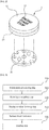
- a light emitting metal knob 1 includes a light blocking metal plate 10 having a light emitting display window 11 and a resin layer 20, made of a light transmitting synthetic resin, coupled to the lower surface of the light blocking metal plate 10.
- the resin layer 20 is coupled to the lower part of the light blocking metal plate 10 by bonding or by insert injection molding.
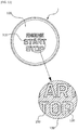
- a light emitting device 30 is installed under the resin layer 20 to display a predetermined message, such as "ENGINE START STOP," outward through the light emitting display window 11 of the light blocking metal plate 10 in a light emitting fashion.
- the method for manufacturing the conventional light emitting metal knob includes a metal plate processing step (S10) of processing a light blocking metal plate 10 such that the upper part of the light blocking metal plate is closed and the lower part of the light blocking metal plate is open, a resin layer coupling step (S20) of coupling a resin layer 20, which is made of a light transmitting synthetic resin, to the inner side of the lower part of the light blocking metal plate 10, a display window forming step (S30) of forming a light emitting display window 11 in the upper surface of the light blocking metal plate 10 by carving, a surface treatment step (S40) of treating the upper surface of the light blocking metal plate 10, in which the light emitting display window 11 is formed, and a coating step (S50) of coating the treated upper surface of the light blocking metal plate 10.
- a metal plate processing step (S10) of processing a light blocking metal plate 10 such that the upper part of the light blocking metal plate is closed and the lower part of the light blocking metal plate is open
- letters such as E, N, G, I, N, S, and T, the start and the end of a cutoff line of each of which are attached to the light blocking metal plate 10, of "ENGINE START STOP," which is the message, displayed through the light emitting display window 11, which is widely used, are not separated from the resin layer 20.
- the present invention has been made to solve the above problems, and it is an object of the present invention to provide a method for manufacturing a light emitting metal knob based on a novel process that is capable of preventing a letter that is separated from a light blocking metal plate at a display window forming step from being separated from a resin layer irrespective of the shape or the type of the letter, which constitutes a light emitting display window, thereby considerably reducing a defect rate.
- a method for manufacturing a light emitting metal knob includes a metal plate processing step of processing a light blocking metal plate such that an upper part of the light blocking metal plate is closed and a lower part of the light blocking metal plate is open; a display groove forming step of forming a light emitting display groove in an upper surface of the light blocking metal plate; a first resin layer coupling step of coupling a first resin layer, which is made of a light transmitting synthetic resin, to the upper surface of the light blocking metal plate so as to fill the light emitting display groove; an upper surface plane-cutting step of cutting the upper surface of the light blocking metal plate planarly so that the first resin layer filled in the light emitting display groove is left; an anodizing step of applying an anodic oxidation treatment to the surface of the light blocking metal plate and then absorbing an organic dye to realize color; a lower surface plane-cutting step of cutting a lower surface of the light blocking metal plate planarly such that the first resin layer coupled into the light emit
- the metal plate processing step may include processing a plate-shaped metal material by pressing to manufacture the light blocking metal plate.
- the method according to the present invention may further include a surface treatment step performing between the display groove forming step and the first resin layer coupling step, to surface-treat the light blocking metal plate to increase a coupling force of the first resin layer to the light blocking metal plate.
- the surface treatment step may include treating a surface of the light blocking metal plate to increase the oxygen content to form an oxygen-containing film containing oxygen; and the first resin layer coupling step may include the first resin layer contains an additive compound having a functional group that reacts with the oxygen-containing film as a thermoplastic resin composition, wherein the additive compound is selected from the group consisting of a carboxyl group, a salt thereof and ester thereof, an epoxy group, a glycidyl group, an isocyanate group, a carbodiimide group, an amino group and a salt thereof, an acid anhydride group and an ester thereof.
- the additive compound is selected from the group consisting of a carboxyl group, a salt thereof and ester thereof, an epoxy group, a glycidyl group, an isocyanate group, a carbodiimide group, an amino group and a salt thereof, an acid anhydride group and an ester thereof.
- the method according to the present invention may further include a sandblasting step performing between the upper surface plane-cutting step and the anodizing step, to sandblast a surface of the light blocking metal plate to make the surface clean.
- the first resin layer coupling step may include the first resin layer is bonded to the upper surface of the light blocking metal plate or the first resin layer is insert injection molded by using the light blocking metal plate as an insert.
- the second resin layer coupling step may include the second resin layer is bonded to the lower surface of the light blocking metal plate or the first resin layer is insert injection molded by using the light blocking metal plate as an insert.
- the method according to the present invention may further include a coating step of coating the upper surface of the light blocking metal plate.
- the coating step may include coating the upper surface of the light blocking metal plate with hard urethane.
- the method for manufacturing the light emitting metal knob according to the present invention has the following effects.
- the light emitting display groove is formed on the upper surface of the light blocking metal plate at the display groove forming step, and then the first resin layer is filled in the light emitting display groove at the first resin layer coupling step and the upper surface plane-cutting step, the letters to be separated from the light blocking metal plate is maintained in a state where the lower surface and the side surface are firmly coupled by the first resin layer and the second resing layer through the lower surface plane-cutting step and the second resin layer coupling step, thereby considerably reducing a defect rate.
- the first resin layer is coupled to the light emitting display groove through the upper surface plane-cutting step after the display groove forming step and the first resin layer coupling step, since the metal connection between the light blocking metal plate and the letters to be separated is maintained, thereby the color of the surface can be realized even the letters to be separated from the light blocking metal plate when the anodizing processing.
- an oxygen-containing film is formed on the surface of the light blocking metal plate through the surface treatment step and an additive compound having a functional group reactive with the oxygen-containing film is contained in the first resin layer at the first resin layer coupling step, thereby a strong coupling force between the two dissimilar materials can be obtained and there is an effect of preventing the first resin layer from being separated from the light blocking metal plate together with the letters to be separated.
- the method for manufacturing the light emitting knob according to the present invention may include a metal plate processing step (S100), a display groove forming step (S200), a first resin layer coupling step (S300), an upper surface plane-cutting step (S400), an anodizing step (S500), and a lower surface plane-cutting step (S600).
- the method for manufacturing the light emitting metal knob according to the present invention may further include a surface treatment step (S250) and a sandblasting step (S450).
- the method for manufacturing the light emitting metal knob according to the present invention may further include a coating step (S800).
- a light blocking metal plate 100 is processed such that the upper part of the light blocking metal plate 100 is closed and the lower part of the light blocking metal plate 100 is open.
- the light blocking metal plate 100 is made of a plate-shaped metal material. As compared with a conventional synthetic resin, the light blocking metal plate 100 has an aesthetically pleasing appearance due to the luxurious characteristics of metal.
- the light blocking metal plate 100 has various shapes based on the function and type of the light emitting metal knob 1. As shown in FIG.
- the upper part of the light blocking metal plate 100 is closed and the lower part of the light blocking metal plate 100 is open such that the light blocking metal plate 100 blocks light from the light emitting device 30, which emits light under the light blocking metal plate 100, and such that the lower part of the light blocking metal plate 100 is coupled to the light emitting device 30.
- the light blocking metal plate 100 may be processed using various processing methods, such as cutting, casting, and injection molding, such that the upper part of the light blocking metal plate 100 is closed and the lower part of the light blocking metal plate 100 is open. As shown in FIG. 7 , however, a plate-shaped metal material may be processed by pressing to manufacture the light blocking metal plate 100, which is most suitable for mass production, considering that the light blocking metal plate 100 is made of a plate-shaped material.
- a light emitting display groove 110 is formed in the upper surface of the light blocking metal plate 100.
- the light blocking metal plate 100 is configured such that the upper part of the light blocking metal plate 100 is closed and the lower part of the light blocking metal plate 100 is open, as shown in FIGS. 6 to 8 , the light blocking metal plate 100 has a '[' shape, in which the lower part of the light blocking metal plate 100 is open when viewed in side section.
- the light emitting display groove 110 is formed in the exposed upper surface of the light blocking metal plate 100 such that the light emitting display groove 110 has the same shape as a letter or a symbol of a light emitting display window 120, which will be described hereinafter. As shown in FIGS. 7 and 8 , carving may be used to form the light emitting display groove 110 in the upper surface of the light blocking metal plate 100. Alternatively, various other processing methods, such as pressing, punching, and chemical hatching, may be used to form the light emitting display groove 110 in the upper surface of the light blocking metal plate 100.
- any processing methods may be used as long as, at the display groove forming step (S200), the light emitting display groove 110 is formed in the upper surface of the light blocking metal plate 100 such that the light emitting display groove 110 has the same shape as the light emitting display window 120, which will be described hereinafter.
- the display groove forming step (S200) is carried out after the metal plate processing step (S100) considering the order of the reference symbols or the sequence of the flowchart shown in the drawings.
- the sequence in which the metal plate processing step (S100) and the display groove forming step (S200) are carried out is not particularly restricted. That is, at the display groove forming step (S200), the light emitting display groove 110 may be formed in advance in a portion of the plate-shaped metal material which will become the upper surface of the light blocking metal plate 100 at the metal plate processing step (S100), and then the metal plate processing step (S100) may be carried out. Alternatively, the metal plate processing step (S100) and the display groove forming step (S200) may be simultaneously carried out such that the light blocking metal plate 100 is processed by pressing simultaneously when the light emitting display groove 110 is formed.
- a first resin layer 200 which is made of a light transmitting synthetic resin, is coupled to the upper surface of the light blocking metal plate 100 so as to fill the light emitting display groove 110. Since the first resin layer 200 is made of a light transmitting synthetic resin, light emitted from the light emitting device 30 may be transmitted through the first resin layer 200 such that the light reaches the light blocking metal plate 100.
- the first resin layer 200 may be manufactured in advance so as to have a shape in which the first resin layer 200 can be inserted into and fitted in the light blocking metal plate 100, and may then be coupled to the light blocking metal plate 100 by bonding.
- the first resin layer 200 may be formed by insert injection molding using the light blocking metal plate 100 as an insert such that the light blocking metal plate 100 is coupled to the first resin layer 200.
- the upper surface of the light blocking metal plate 100 is cut planarly so that the first resin layer 200 filled in the light emitting display groove 110 is left.
- the first resin layer 200 is coupled to the entire upper surface of the light blocking metal plate 100 in the first resin layer coupling step (S300).
- the upper surface of the light blocking metal plate 100 excluding the light emitting display groove 110 is cut planarly so that the exposed upper surface becomes a metal surface through the upper surface plane-cutting step (S400).
- the first resin layer 200 filled in the light emitting display groove 110 as well as the letters to be separated is firmly coupled to the first resin layer 200.
- the metal connection between the light blocking metal plate 100 and the letters to be separated is maintained.
- the surface of the light blocking metal plate 100 is applied an anodic oxidation treatment and then absorbed an organic dye to realize color.
- the anodizing treatment that is, anodizing is performed by immersing the light blocking metal plate 100 as an anode in an aqueous solution of sulfuric acid, nitric acid, or the like, which is an electrolyte, and then flowing an electric current.
- oxygen is generated in the light blocking metal plate 100 by electrolysis, and this oxygen is oxidized to form an oxide film on the surface of the light blocking metal plate 100.
- This oxide film does not dissolve even when exposed to solution and acid, thus protecting the metal.
- the organic dye is adsorbed on the thus formed oxide film, various desired colors can be expressed.
- this anodizing step (S500) since the light blocking metal plate 100 becomes an anode and a current should flow to the letters to be separated, the metal connection between the light blocking metal plate 100 and the letters to be separated should be maintained. Therefore, the grooves are formed so as not penetrate through the light emitting display groove 110 on the upper surface of the light blocking metal plate 100, and after the first resin layer 200 is coupled to the light emitting display groove 110 in a state where the metal connection between the letters to be separated and the light blocking metal plate 100 is maintained, and then the upper surface plane-cutting step (S400) is performed so that the metal surface is exposed on the upper surface of the light blocking metal plate 100.
- the light emitting display groove 110 of the light blocking metal plate 100 having completed the anodizing process should be changed to the light emitting display window 120 so that the light is transmitted because the entire lower surface is still a metal surface. Therefore, At the lower surface plane-cutting step (S600), as shown in FIGS. 6 , 7 , and 10 , the lower surface of the light blocking metal plate 100 is cut planarly such that the first resin layer 200 coupled into the light emitting display groove 110 is exposed from the lower surface of the light blocking metal plate 100 to form a light emitting display window 120. That is, if the lower surface of the light emitting display groove 110 is blocked by the metal surface of the light blocking metal plate 100, light emitted from the light emitting device 30 cannot emit upward from the light emitting display groove 110.
- the light emitting display groove 110 is completely exposed upward and downward, as a hole or an opend window, so that the light emitting display window 120 is formed.
- the first resin layer 200 is exposed upward and downward so that light can be transmitted through the light emitting display window 120.
- the light emitting metal knob 1 is normally formed in a push-button type, a structure capable of supporting the lower surface of the first resin layer 200 is required, and the structure should be made of a light transmitting material.
- a second resin layer 300 which is made of a light transmitting synthetic resin, is coupled to the lower surface of the light blocking metal plate 100. Since the second resin layer 300 is also a light transmitting synthetic resin, light emitted from the light emitting device 30 can be transmitted to the outside. That is, light emitted from the light emitting device 30 passes through the second resin layer 300 and emits upward from the first resin layer 200.
- the second resin layer 300 When the second resin layer 300 is coupled to the lower surface of the light blocking metal plate 100, first the second resin layer 300 is formed in advance so that the lower surface of the light blocking metal plate 100 can be inserted, or the second resin layer 300 may be insert injection-molded by using the light blocking metal plate 100 as an insert.
- the second resin layer 300 may be formed with a bracket, a protrusion, or a protruding groove, though it is not shown in the figure for coupling with another member in a lower portion.
- the surface treatment step (S250) is performed between the display groove forming step (S200) and the first resin layer coupling step (S300) as shown in FIG. 12 .
- the light blocking metal plate 100 is surface-treated to increase a coupling force of the first resin layer 200 to the light blocking metal plate 100. More specifically, as the surface treatment for increasing the coupling force of the first resin layer 200 by injection molding using the light blocking metal plate 100 made of a metal material as an insert, there is a mechanical insertion method by the concave and convex shapes, and the coupling force with the first resin layer 200 can be increased through a chemical treatment such as etching on the light blocking metal plate 100 made of a metal material.
- an oxygen-containing film is formed on the surface of the light blocking metal plate 100 in order to maximize the coupling force between the light blocking metal plate 100 made of a metal material and the first resin layer 200, by adding an additive compound having a functional group reactive with the oxygen-containing film, a strong coupling force between the two dissimilar materials can be obtained. That is, at the surface treatment step (S250), the surface of the light blocking metal plate 100 is treated to increase the oxygen content to form the oxygen-containing film containing oxygen.
- the first resin layer 200 contains an additive compound having a functional group that reacts with the oxygen-containing film as a thermoplastic resin composition, wherein the additive compound is selected from the group consisting of a carboxyl group, a salt thereof and ester thereof, an epoxy group, a glycidyl group, an isocyanate group, a carbodiimide group, an amino group and a salt thereof, an acid anhydride group and an ester thereof.
- the additive compound is selected from the group consisting of a carboxyl group, a salt thereof and ester thereof, an epoxy group, a glycidyl group, an isocyanate group, a carbodiimide group, an amino group and a salt thereof, an acid anhydride group and an ester thereof.
- the method of forming the oxygen-containing film on the surface of the light blocking metal plate 100 by increasing the oxygen content is as follows. First, the light blocking metal plate 100 is immersed in an aqueous zinc-ion-containing sodium solution to form a zinc-containing film, and thereafter, the zinc-containing film containing zinc element as the oxygen- containing film on the surface is formed. Second and third, the surface of the light blocking metal plate 100 is formed a hydrated oxide film by the hot water or warm water. Fourth, an oxide film is formed on the surface of the light blocking metal plate 100 by laser.
- the light blocking metal plate 100 which has been surface-treated so as to form the oxygen-containing film, is used as an insert, and as the thermoplastic resin composition, the first resin layer 200 containing the additive compound having the functional group reactive with the oxygen-containing film is injection-molded so that a strong and firm coupling force can be obtained.
- a sandblasting step (S450) may be performed as shown in FIG. 12 . That is, the sandblasting step (S450) is performed between the upper surface plane-cutting step (S400) and the anodizing step (S500), and the surface of the light blocking metal plate 100 is sandblasted to make the surface smooth.
- the sandblasting is effective in removing the dirt, oil, and other impurities by mixing the sand with high-pressure water and spraying the sand on the surface of the light blocking metal plate 100 to enhance the strength and surface quality.
- the sandblasting step (S450) is performed before the anodizing step (S500) to smooth the surface roughness.
- the upper surface of the light blocking metal plate 100 is coated. Coating includes putting a thin film of paraffin, rubber resin, or a chemical material on the surface of a material.
- the surface of the light blocking metal plate 100 is coated with hard urethane 400.
- the hard urethane 400 is formed in a semi-transparent state.
- the upper surface of the light blocking metal plate 100 is coated with the hard urethane 400, and is then dried. As a result, it is possible to improve the visibility of light emitted through the light emitting display window 120.
- the light blocking metal plate 100 is coated with the hard urethane 400, it is possible to avoid leaving fingerprints on the upper surface of the light blocking metal plate 100 and to provide the light blocking metal plate 100 with an aesthetically pleasing appearance.
- the light emitting display groove 110 is formed on the upper surface of the light blocking metal plate at the display groove forming step (S200), and then the first resin layer 200 is filled in the light emitting display groove 110 at the first resin layer coupling step (S300) and the upper surface plane-cutting step (S400), the letters to be separated from the light blocking metal plate 100 is maintained in a state where the lower surface and the side surface are firmly coupled by the first resin layer 200 and the second resin layer 300 through the lower surface plane-cutting step (S600) and the second resin layer coupling step (S700), thereby considerably reducing a defect rate.
- the first resin layer 200 is coupled to the light emitting display groove 110 through the upper surface plane-cutting step (S400) after the display groove forming step (S200) and the first resin layer coupling step (S300), since the metal connection between the light blocking metal plate 100 and the letters to be separated is maintained, thereby the color of the surface can be realized even the letters to be separated from the light blocking metal plate 100 when the anodizing processing.
- an oxygen-containing film is formed on the surface of the light blocking metal plate 100 through the surface treatment step (S250) and an additive compound having a functional group reactive with the oxygen-containing film is contained in the first resin layer 200 at the first resin layer coupling step (S300), thereby a strong coupling force between the two dissimilar materials can be obtained and there is an effect of preventing the first resin layer 200 from being separated from the light blocking metal plate 100 together with the letters to be separated.
Landscapes
- Engineering & Computer Science (AREA)
- Manufacturing & Machinery (AREA)
- Mechanical Engineering (AREA)
- Physics & Mathematics (AREA)
- General Physics & Mathematics (AREA)
- Automation & Control Theory (AREA)
- Chemical & Material Sciences (AREA)
- Chemical Kinetics & Catalysis (AREA)
- Electrochemistry (AREA)
- Materials Engineering (AREA)
- Metallurgy (AREA)
- Organic Chemistry (AREA)
- Injection Moulding Of Plastics Or The Like (AREA)
- Manufacture Of Switches (AREA)
Claims (9)
- Verfahren zum Herstellen eines lichtemittierenden Metallknopfs, umfassend:einen Metallplattenbearbeitungsschritt, wobei eine lichtblockierende Metallplatte derart bearbeitet wird, dass ein oberer Teil der lichtblockierenden Metallplatte geschlossen und ein unterer Teil der lichtblockierenden Metallplatte offen ist;einen Anzeigenutenformungsschritt, wobei eine lichtemittierende Anzeigenut in einer oberen Oberfläche der lichtblockierenden Metallplatte geformt wird;einen ersten Harzschichtkopplungsschritt, wobei eine erste Harzschicht, die aus einem lichtdurchlässigen Kunstharz hergestellt ist, an die obere Oberfläche der lichtblockierenden Metallplatte gekoppelt wird, um die lichtemittierende Anzeigenut zu füllen;einen Obere-Oberflächen-Planschneideschritt, wobei die obere Oberfläche der lichtblockierenden Metallplatte planar geschnitten wird, so dass nur die erste, in die lichtemittierende Anzeigenut gefüllte, Harzschicht zurückbleibt;einen Anodisierungsschritt, wobei eine anodische Oxidationsbehandlung auf die Oberfläche der lichtblockierenden Metallplatte angewendet wird und wobei anschließend ein organischer Farbstoff absorbiert wird, um eine Farbe zu realisieren;einen Untere-Oberflächen-Planschneideschritt, wobei eine untere Oberfläche der lichtblockierenden Metallplatte planar geschnitten wird, so dass nur die erste, in die lichtemittierende Anzeigenut eingekoppelte, Harzschicht von der unteren Oberfläche der lichtblockierenden Metallplatte freigelegt wird, um ein lichtemittierendes Anzeigefenster zu bilden; undeinen zweiten Harzschichtkopplungsschritt, wobei eine zweite Harzschicht, die aus einem lichtdurchlässigen Kunstharz hergestellt ist, an die untere Oberfläche der lichtblockierenden Metallplatte gekoppelt wird.
- Verfahren gemäß Anspruch 1, wobei der Metallplattenbearbeitungsschritt das Bearbeiten eines plattenförmigen Metallmaterials durch Pressen umfasst, um die lichtblockierende Metallplatte herzustellen.
- Verfahren gemäß Anspruch 1, ferner umfassend einen Oberflächenbehandlungsschritt, der zwischen dem Anzeigenutenformungsschritt und dem ersten Harzschichtkopplungsschritt durchgeführt wird, um die lichtblockierende Metallplatte einer Oberflächenbehandlung zu unterziehen, um eine Kopplungskraft der ersten Harzschicht an die lichtblockierende Metallplatte zu erhöhen.
- Verfahren gemäß Anspruch 3, wobei der Oberflächenbehandlungsschritt das Behandeln einer Oberfläche der lichtblockierenden Metallplatte umfasst, um den Sauerstoffgehalt zu erhöhen, um einen sauerstoffhaltigen Film zu bilden, der Sauerstoff enthält; und
wobei der erste Harzschichtkopplungsschritt die erste Harzschicht umfasst, die eine Additivverbindung aufweisend eine funktionelle Gruppe enthält, die mit dem sauerstoffhaltigen Film als thermoplastische Harzzusammensetzung reagiert, wobei die Additivverbindung ausgewählt ist aus der Gruppe bestehend aus einer Carboxylgruppe, einem Salz davon und einem Ester davon, einer Epoxygruppe, einer Glycidylgruppe, einer Isocyanatgruppe, einer Carbodiimidgruppe, einer Aminogruppe und einem Salz davon, einer Säureanhydridgruppe und einem Ester davon. - Verfahren gemäß Anspruch 1, ferner umfassend einen Sandstrahlschritt, der zwischen dem Obere-Oberflächen-Planschneideschritt und dem Anodisierungsschritt durchgeführt wird, um eine Oberfläche der lichtblockierenden Metallplatte zu sandstrahlen, um die Oberfläche sauber zu machen.
- Verfahren gemäß Anspruch 1, wobei der erste Harzschichtkopplungsschritt einen Schritt umfasst, in dem die erste Harzschicht an die obere Oberfläche der lichtblockierenden Metallplatte gebunden wird oder die erste Harzschicht unter Verwendung der lichtblockierenden Metallplatte als Einsatz spritzgegossen wird.
- Verfahren nach Anspruch 1, wobei der zweite Harzschichtkopplungsschritt einen Schritt umfasst: in dem die zweite Harzschicht an die untere Oberfläche der lichtblockierenden Metallplatte gebunden wird oder die zweite Harzschicht unter Verwendung der lichtblockierenden Metallplatte als Einsatz spritzgegossen wird.
- Verfahren gemäß Anspruch 1, ferner umfassend einen Beschichtungsschritt des Beschichtens der oberen Oberfläche der lichtblockierenden Metallplatte.
- Verfahren gemäß Anspruch 8, wobei der Beschichtungsschritt das Beschichten der oberen Oberfläche der lichtblockierenden Metallplatte mit hartem Urethan umfasst.
Applications Claiming Priority (2)
| Application Number | Priority Date | Filing Date | Title |
|---|---|---|---|
| KR1020170009532A KR101707789B1 (ko) | 2017-01-20 | 2017-01-20 | 광발산 메탈노브의 제조방법 |
| PCT/KR2017/011185 WO2018135721A1 (ko) | 2017-01-20 | 2017-10-11 | 광발산 메탈노브의 제조방법 |
Publications (3)
| Publication Number | Publication Date |
|---|---|
| EP3376517A1 EP3376517A1 (de) | 2018-09-19 |
| EP3376517A4 EP3376517A4 (de) | 2019-07-24 |
| EP3376517B1 true EP3376517B1 (de) | 2020-03-11 |
Family
ID=58265177
Family Applications (1)
| Application Number | Title | Priority Date | Filing Date |
|---|---|---|---|
| EP17798088.5A Active EP3376517B1 (de) | 2017-01-20 | 2017-10-11 | Verfahren zur herstellung eines lichtemittierenden metallknopfes |
Country Status (5)
| Country | Link |
|---|---|
| US (1) | US10139853B2 (de) |
| EP (1) | EP3376517B1 (de) |
| KR (1) | KR101707789B1 (de) |
| CN (1) | CN108701557B (de) |
| WO (1) | WO2018135721A1 (de) |
Families Citing this family (6)
| Publication number | Priority date | Publication date | Assignee | Title |
|---|---|---|---|---|
| US10777370B1 (en) * | 2018-01-03 | 2020-09-15 | David Worsham | Pushbutton switch with light-transmitting indicia on the pushbutton |
| EP3594775B1 (de) * | 2018-07-09 | 2022-05-25 | Marquardt GmbH | Verfahren zur herstellung eines bauteils |
| CN110942944B (zh) * | 2018-09-21 | 2022-08-23 | 光宝科技(常州)有限公司 | 一种发光按键、键帽制造方法、键盘装置及电子装置 |
| EP3867573B1 (de) | 2018-10-18 | 2025-08-06 | Channel Products, Inc. | Gasgeräte-zündmodul |
| USD939456S1 (en) * | 2019-10-18 | 2021-12-28 | Channel Products, Inc. | Gas appliance ignition switch |
| KR102829832B1 (ko) * | 2020-02-26 | 2025-07-03 | 현대자동차주식회사 | 스위치 구조 및 이의 제작 방법 |
Family Cites Families (12)
| Publication number | Priority date | Publication date | Assignee | Title |
|---|---|---|---|---|
| DE60221486T2 (de) * | 2001-11-28 | 2008-04-10 | Polymatech Co. Ltd. | Tastenfolie |
| US6905777B2 (en) * | 2003-04-18 | 2005-06-14 | Shannon D. Near | Laminate material |
| KR100914786B1 (ko) * | 2007-09-12 | 2009-09-01 | 주식회사 코텍 | 금속체와 수지의 복합물 제조방법 |
| JP2009146642A (ja) * | 2007-12-12 | 2009-07-02 | Polymatech Co Ltd | キーシート |
| CN101488405B (zh) * | 2008-01-16 | 2010-12-22 | 毅嘉科技股份有限公司 | 侧向发光键帽制造方法 |
| KR101210906B1 (ko) * | 2012-06-27 | 2012-12-11 | 나순희 | 광발산 조절노브 |
| JP6045704B2 (ja) * | 2012-09-10 | 2016-12-14 | バルカン イノックス ゲーエムベーハー | アルミニウム基板上にサテン仕上げを生成するための方法およびブラスト手段 |
| JP6017675B2 (ja) * | 2013-03-26 | 2016-11-02 | 日本軽金属株式会社 | 金属樹脂接合体及びその製造方法 |
| KR101370256B1 (ko) * | 2013-10-28 | 2014-03-25 | 유재진 | 광발산 조절노브 및 이의 제조방법 |
| KR101412781B1 (ko) | 2013-12-06 | 2014-07-09 | 주식회사 엠엘케이 | 광발산 노브 제조방법 |
| KR101560999B1 (ko) * | 2015-01-14 | 2015-10-15 | 주식회사 우신엠에스 | 광발산 노브의 제조방법 |
| KR101560998B1 (ko) * | 2015-01-14 | 2015-10-15 | 주식회사 우신엠에스 | 광발산 노브의 제조방법 |
-
2017
- 2017-01-20 KR KR1020170009532A patent/KR101707789B1/ko active Active
- 2017-10-11 CN CN201780001701.9A patent/CN108701557B/zh not_active Expired - Fee Related
- 2017-10-11 WO PCT/KR2017/011185 patent/WO2018135721A1/ko not_active Ceased
- 2017-10-11 EP EP17798088.5A patent/EP3376517B1/de active Active
- 2017-11-01 US US15/800,716 patent/US10139853B2/en active Active
Non-Patent Citations (1)
| Title |
|---|
| None * |
Also Published As
| Publication number | Publication date |
|---|---|
| CN108701557A (zh) | 2018-10-23 |
| US10139853B2 (en) | 2018-11-27 |
| WO2018135721A1 (ko) | 2018-07-26 |
| US20180210486A1 (en) | 2018-07-26 |
| EP3376517A4 (de) | 2019-07-24 |
| EP3376517A1 (de) | 2018-09-19 |
| KR101707789B1 (ko) | 2017-02-20 |
| CN108701557B (zh) | 2019-06-28 |
Similar Documents
| Publication | Publication Date | Title |
|---|---|---|
| EP3376517A1 (de) | Verfahren zur herstellung eines lichtemittierenden metallknopfes | |
| US6764626B2 (en) | Method of galvanizing part of a piece obtained by injection molding | |
| CN106903839B (zh) | 金属/树脂复合结构体、金属构件以及应用 | |
| US9443676B2 (en) | Light emitting control knob | |
| KR100914786B1 (ko) | 금속체와 수지의 복합물 제조방법 | |
| US20160201878A1 (en) | Method for manufacturing light emitting knob | |
| WO2004041533A1 (ja) | アルミニウム合金と樹脂組成物の複合体とその製造方法 | |
| US20150116978A1 (en) | Light-emitting button key and manufacturing method thereof | |
| KR20110040094A (ko) | 금속박 적층 필름 및 그 제조 방법 | |
| CN105522684A (zh) | 一种金属-树脂复合体及其制备方法和一种电子产品外壳 | |
| KR101846729B1 (ko) | 차량용 수지 부품의 부분 금속 도금 방법 및 이를 이용한 부분 금속 도금된 차량용 수지 부품 | |
| US20190255877A1 (en) | Substrates with patterned surfaces | |
| FR2780806A1 (fr) | Procede de fabrication d'un clavier transparent de type a revetement etanche a l'eau | |
| KR101370256B1 (ko) | 광발산 조절노브 및 이의 제조방법 | |
| MXPA05011504A (es) | Componente de moldeo para resina multicolor para un aparato movil. | |
| KR100575299B1 (ko) | 광택사면을 갖는 아노다이징처리 외장제품 제조방법 및이에 의해 제조된 외장제품 | |
| KR101560999B1 (ko) | 광발산 노브의 제조방법 | |
| KR101561000B1 (ko) | 광발산 노브의 제조방법 | |
| KR101912762B1 (ko) | 제품의 표면 각인 방법 및 이를 이용하여 제조되는 제품 | |
| KR20100138490A (ko) | 자동차 엠블럼 및 그 제조방법 | |
| CN201423874Y (zh) | 塑胶制品饰面结构 | |
| KR100284649B1 (ko) | 단추 및 그의 제조방법 | |
| WO2021045774A1 (en) | Dual injection-molded metal substrates | |
| JP2006294346A (ja) | 押釦スイッチ用キートップの製造方法および押釦スイッチ用キートップ | |
| JP2013215998A (ja) | 加飾パネル及びその製造方法 |
Legal Events
| Date | Code | Title | Description |
|---|---|---|---|
| STAA | Information on the status of an ep patent application or granted ep patent |
Free format text: STATUS: UNKNOWN |
|
| STAA | Information on the status of an ep patent application or granted ep patent |
Free format text: STATUS: THE INTERNATIONAL PUBLICATION HAS BEEN MADE |
|
| PUAI | Public reference made under article 153(3) epc to a published international application that has entered the european phase |
Free format text: ORIGINAL CODE: 0009012 |
|
| STAA | Information on the status of an ep patent application or granted ep patent |
Free format text: STATUS: REQUEST FOR EXAMINATION WAS MADE |
|
| 17P | Request for examination filed |
Effective date: 20171124 |
|
| AK | Designated contracting states |
Kind code of ref document: A1 Designated state(s): AL AT BE BG CH CY CZ DE DK EE ES FI FR GB GR HR HU IE IS IT LI LT LU LV MC MK MT NL NO PL PT RO RS SE SI SK SM TR |
|
| AX | Request for extension of the european patent |
Extension state: BA ME |
|
| A4 | Supplementary search report drawn up and despatched |
Effective date: 20190621 |
|
| RIC1 | Information provided on ipc code assigned before grant |
Ipc: H01H 11/00 20060101AFI20190614BHEP Ipc: B29L 31/00 20060101ALI20190614BHEP Ipc: C25D 11/24 20060101ALI20190614BHEP Ipc: G05G 1/02 20060101ALI20190614BHEP Ipc: H01H 9/18 20060101ALI20190614BHEP Ipc: B29C 45/14 20060101ALI20190614BHEP Ipc: B29C 45/16 20060101ALI20190614BHEP |
|
| GRAP | Despatch of communication of intention to grant a patent |
Free format text: ORIGINAL CODE: EPIDOSNIGR1 |
|
| STAA | Information on the status of an ep patent application or granted ep patent |
Free format text: STATUS: GRANT OF PATENT IS INTENDED |
|
| DAV | Request for validation of the european patent (deleted) | ||
| DAX | Request for extension of the european patent (deleted) | ||
| INTG | Intention to grant announced |
Effective date: 20190926 |
|
| GRAS | Grant fee paid |
Free format text: ORIGINAL CODE: EPIDOSNIGR3 |
|
| GRAA | (expected) grant |
Free format text: ORIGINAL CODE: 0009210 |
|
| STAA | Information on the status of an ep patent application or granted ep patent |
Free format text: STATUS: THE PATENT HAS BEEN GRANTED |
|
| RIN1 | Information on inventor provided before grant (corrected) |
Inventor name: CHOI, JAE HO Inventor name: KIM, HARRISON SANG WHA |
|
| AK | Designated contracting states |
Kind code of ref document: B1 Designated state(s): AL AT BE BG CH CY CZ DE DK EE ES FI FR GB GR HR HU IE IS IT LI LT LU LV MC MK MT NL NO PL PT RO RS SE SI SK SM TR |
|
| RAP1 | Party data changed (applicant data changed or rights of an application transferred) |
Owner name: CHOI, JAE HO |
|
| REG | Reference to a national code |
Ref country code: GB Ref legal event code: FG4D |
|
| RIN1 | Information on inventor provided before grant (corrected) |
Inventor name: KIM, HARRISON SANG WHA Inventor name: CHOI, JAE HO |
|
| REG | Reference to a national code |
Ref country code: CH Ref legal event code: EP |
|
| REG | Reference to a national code |
Ref country code: AT Ref legal event code: REF Ref document number: 1244161 Country of ref document: AT Kind code of ref document: T Effective date: 20200315 |
|
| REG | Reference to a national code |
Ref country code: IE Ref legal event code: FG4D |
|
| REG | Reference to a national code |
Ref country code: DE Ref legal event code: R096 Ref document number: 602017013062 Country of ref document: DE |
|
| PG25 | Lapsed in a contracting state [announced via postgrant information from national office to epo] |
Ref country code: FI Free format text: LAPSE BECAUSE OF FAILURE TO SUBMIT A TRANSLATION OF THE DESCRIPTION OR TO PAY THE FEE WITHIN THE PRESCRIBED TIME-LIMIT Effective date: 20200311 Ref country code: RS Free format text: LAPSE BECAUSE OF FAILURE TO SUBMIT A TRANSLATION OF THE DESCRIPTION OR TO PAY THE FEE WITHIN THE PRESCRIBED TIME-LIMIT Effective date: 20200311 Ref country code: NO Free format text: LAPSE BECAUSE OF FAILURE TO SUBMIT A TRANSLATION OF THE DESCRIPTION OR TO PAY THE FEE WITHIN THE PRESCRIBED TIME-LIMIT Effective date: 20200611 |
|
| REG | Reference to a national code |
Ref country code: NL Ref legal event code: MP Effective date: 20200311 |
|
| PG25 | Lapsed in a contracting state [announced via postgrant information from national office to epo] |
Ref country code: BG Free format text: LAPSE BECAUSE OF FAILURE TO SUBMIT A TRANSLATION OF THE DESCRIPTION OR TO PAY THE FEE WITHIN THE PRESCRIBED TIME-LIMIT Effective date: 20200611 Ref country code: SE Free format text: LAPSE BECAUSE OF FAILURE TO SUBMIT A TRANSLATION OF THE DESCRIPTION OR TO PAY THE FEE WITHIN THE PRESCRIBED TIME-LIMIT Effective date: 20200311 Ref country code: LV Free format text: LAPSE BECAUSE OF FAILURE TO SUBMIT A TRANSLATION OF THE DESCRIPTION OR TO PAY THE FEE WITHIN THE PRESCRIBED TIME-LIMIT Effective date: 20200311 Ref country code: GR Free format text: LAPSE BECAUSE OF FAILURE TO SUBMIT A TRANSLATION OF THE DESCRIPTION OR TO PAY THE FEE WITHIN THE PRESCRIBED TIME-LIMIT Effective date: 20200612 Ref country code: HR Free format text: LAPSE BECAUSE OF FAILURE TO SUBMIT A TRANSLATION OF THE DESCRIPTION OR TO PAY THE FEE WITHIN THE PRESCRIBED TIME-LIMIT Effective date: 20200311 |
|
| REG | Reference to a national code |
Ref country code: LT Ref legal event code: MG4D |
|
| PG25 | Lapsed in a contracting state [announced via postgrant information from national office to epo] |
Ref country code: NL Free format text: LAPSE BECAUSE OF FAILURE TO SUBMIT A TRANSLATION OF THE DESCRIPTION OR TO PAY THE FEE WITHIN THE PRESCRIBED TIME-LIMIT Effective date: 20200311 |
|
| PG25 | Lapsed in a contracting state [announced via postgrant information from national office to epo] |
Ref country code: PT Free format text: LAPSE BECAUSE OF FAILURE TO SUBMIT A TRANSLATION OF THE DESCRIPTION OR TO PAY THE FEE WITHIN THE PRESCRIBED TIME-LIMIT Effective date: 20200805 Ref country code: EE Free format text: LAPSE BECAUSE OF FAILURE TO SUBMIT A TRANSLATION OF THE DESCRIPTION OR TO PAY THE FEE WITHIN THE PRESCRIBED TIME-LIMIT Effective date: 20200311 Ref country code: SM Free format text: LAPSE BECAUSE OF FAILURE TO SUBMIT A TRANSLATION OF THE DESCRIPTION OR TO PAY THE FEE WITHIN THE PRESCRIBED TIME-LIMIT Effective date: 20200311 Ref country code: SK Free format text: LAPSE BECAUSE OF FAILURE TO SUBMIT A TRANSLATION OF THE DESCRIPTION OR TO PAY THE FEE WITHIN THE PRESCRIBED TIME-LIMIT Effective date: 20200311 Ref country code: RO Free format text: LAPSE BECAUSE OF FAILURE TO SUBMIT A TRANSLATION OF THE DESCRIPTION OR TO PAY THE FEE WITHIN THE PRESCRIBED TIME-LIMIT Effective date: 20200311 Ref country code: IS Free format text: LAPSE BECAUSE OF FAILURE TO SUBMIT A TRANSLATION OF THE DESCRIPTION OR TO PAY THE FEE WITHIN THE PRESCRIBED TIME-LIMIT Effective date: 20200711 Ref country code: LT Free format text: LAPSE BECAUSE OF FAILURE TO SUBMIT A TRANSLATION OF THE DESCRIPTION OR TO PAY THE FEE WITHIN THE PRESCRIBED TIME-LIMIT Effective date: 20200311 Ref country code: CZ Free format text: LAPSE BECAUSE OF FAILURE TO SUBMIT A TRANSLATION OF THE DESCRIPTION OR TO PAY THE FEE WITHIN THE PRESCRIBED TIME-LIMIT Effective date: 20200311 |
|
| REG | Reference to a national code |
Ref country code: AT Ref legal event code: MK05 Ref document number: 1244161 Country of ref document: AT Kind code of ref document: T Effective date: 20200311 |
|
| REG | Reference to a national code |
Ref country code: DE Ref legal event code: R097 Ref document number: 602017013062 Country of ref document: DE |
|
| PLBE | No opposition filed within time limit |
Free format text: ORIGINAL CODE: 0009261 |
|
| STAA | Information on the status of an ep patent application or granted ep patent |
Free format text: STATUS: NO OPPOSITION FILED WITHIN TIME LIMIT |
|
| PG25 | Lapsed in a contracting state [announced via postgrant information from national office to epo] |
Ref country code: IT Free format text: LAPSE BECAUSE OF FAILURE TO SUBMIT A TRANSLATION OF THE DESCRIPTION OR TO PAY THE FEE WITHIN THE PRESCRIBED TIME-LIMIT Effective date: 20200311 Ref country code: DK Free format text: LAPSE BECAUSE OF FAILURE TO SUBMIT A TRANSLATION OF THE DESCRIPTION OR TO PAY THE FEE WITHIN THE PRESCRIBED TIME-LIMIT Effective date: 20200311 Ref country code: AT Free format text: LAPSE BECAUSE OF FAILURE TO SUBMIT A TRANSLATION OF THE DESCRIPTION OR TO PAY THE FEE WITHIN THE PRESCRIBED TIME-LIMIT Effective date: 20200311 Ref country code: ES Free format text: LAPSE BECAUSE OF FAILURE TO SUBMIT A TRANSLATION OF THE DESCRIPTION OR TO PAY THE FEE WITHIN THE PRESCRIBED TIME-LIMIT Effective date: 20200311 |
|
| 26N | No opposition filed |
Effective date: 20201214 |
|
| PG25 | Lapsed in a contracting state [announced via postgrant information from national office to epo] |
Ref country code: SI Free format text: LAPSE BECAUSE OF FAILURE TO SUBMIT A TRANSLATION OF THE DESCRIPTION OR TO PAY THE FEE WITHIN THE PRESCRIBED TIME-LIMIT Effective date: 20200311 Ref country code: PL Free format text: LAPSE BECAUSE OF FAILURE TO SUBMIT A TRANSLATION OF THE DESCRIPTION OR TO PAY THE FEE WITHIN THE PRESCRIBED TIME-LIMIT Effective date: 20200311 |
|
| REG | Reference to a national code |
Ref country code: CH Ref legal event code: PL |
|
| PG25 | Lapsed in a contracting state [announced via postgrant information from national office to epo] |
Ref country code: LU Free format text: LAPSE BECAUSE OF NON-PAYMENT OF DUE FEES Effective date: 20201011 Ref country code: MC Free format text: LAPSE BECAUSE OF FAILURE TO SUBMIT A TRANSLATION OF THE DESCRIPTION OR TO PAY THE FEE WITHIN THE PRESCRIBED TIME-LIMIT Effective date: 20200311 |
|
| REG | Reference to a national code |
Ref country code: BE Ref legal event code: MM Effective date: 20201031 |
|
| PGFP | Annual fee paid to national office [announced via postgrant information from national office to epo] |
Ref country code: FR Payment date: 20210429 Year of fee payment: 4 Ref country code: DE Payment date: 20210426 Year of fee payment: 4 |
|
| PG25 | Lapsed in a contracting state [announced via postgrant information from national office to epo] |
Ref country code: LI Free format text: LAPSE BECAUSE OF NON-PAYMENT OF DUE FEES Effective date: 20201031 Ref country code: CH Free format text: LAPSE BECAUSE OF NON-PAYMENT OF DUE FEES Effective date: 20201031 Ref country code: BE Free format text: LAPSE BECAUSE OF NON-PAYMENT OF DUE FEES Effective date: 20201031 |
|
| PG25 | Lapsed in a contracting state [announced via postgrant information from national office to epo] |
Ref country code: IE Free format text: LAPSE BECAUSE OF NON-PAYMENT OF DUE FEES Effective date: 20201011 |
|
| REG | Reference to a national code |
Ref country code: DE Ref legal event code: R119 Ref document number: 602017013062 Country of ref document: DE |
|
| PG25 | Lapsed in a contracting state [announced via postgrant information from national office to epo] |
Ref country code: TR Free format text: LAPSE BECAUSE OF FAILURE TO SUBMIT A TRANSLATION OF THE DESCRIPTION OR TO PAY THE FEE WITHIN THE PRESCRIBED TIME-LIMIT Effective date: 20200311 Ref country code: MT Free format text: LAPSE BECAUSE OF FAILURE TO SUBMIT A TRANSLATION OF THE DESCRIPTION OR TO PAY THE FEE WITHIN THE PRESCRIBED TIME-LIMIT Effective date: 20200311 Ref country code: CY Free format text: LAPSE BECAUSE OF FAILURE TO SUBMIT A TRANSLATION OF THE DESCRIPTION OR TO PAY THE FEE WITHIN THE PRESCRIBED TIME-LIMIT Effective date: 20200311 |
|
| GBPC | Gb: european patent ceased through non-payment of renewal fee |
Effective date: 20211011 |
|
| PG25 | Lapsed in a contracting state [announced via postgrant information from national office to epo] |
Ref country code: MK Free format text: LAPSE BECAUSE OF FAILURE TO SUBMIT A TRANSLATION OF THE DESCRIPTION OR TO PAY THE FEE WITHIN THE PRESCRIBED TIME-LIMIT Effective date: 20200311 Ref country code: AL Free format text: LAPSE BECAUSE OF FAILURE TO SUBMIT A TRANSLATION OF THE DESCRIPTION OR TO PAY THE FEE WITHIN THE PRESCRIBED TIME-LIMIT Effective date: 20200311 |
|
| PG25 | Lapsed in a contracting state [announced via postgrant information from national office to epo] |
Ref country code: GB Free format text: LAPSE BECAUSE OF NON-PAYMENT OF DUE FEES Effective date: 20211011 Ref country code: DE Free format text: LAPSE BECAUSE OF NON-PAYMENT OF DUE FEES Effective date: 20220503 |
|
| PG25 | Lapsed in a contracting state [announced via postgrant information from national office to epo] |
Ref country code: FR Free format text: LAPSE BECAUSE OF NON-PAYMENT OF DUE FEES Effective date: 20211031 |