EP3376216A1 - Verfahren zum wirbelstromtesten von elektrisch leitenden objekten und vorrichtung zur durchführung des besagten verfahrens - Google Patents
Verfahren zum wirbelstromtesten von elektrisch leitenden objekten und vorrichtung zur durchführung des besagten verfahrens Download PDFInfo
- Publication number
- EP3376216A1 EP3376216A1 EP16864656.0A EP16864656A EP3376216A1 EP 3376216 A1 EP3376216 A1 EP 3376216A1 EP 16864656 A EP16864656 A EP 16864656A EP 3376216 A1 EP3376216 A1 EP 3376216A1
- Authority
- EP
- European Patent Office
- Prior art keywords
- eddy
- electrically conductive
- electromagnetic field
- current transducer
- current
- Prior art date
- Legal status (The legal status is an assumption and is not a legal conclusion. Google has not performed a legal analysis and makes no representation as to the accuracy of the status listed.)
- Granted
Links
Images


Classifications
-
- G—PHYSICS
- G01—MEASURING; TESTING
- G01N—INVESTIGATING OR ANALYSING MATERIALS BY DETERMINING THEIR CHEMICAL OR PHYSICAL PROPERTIES
- G01N27/00—Investigating or analysing materials by the use of electric, electrochemical, or magnetic means
- G01N27/72—Investigating or analysing materials by the use of electric, electrochemical, or magnetic means by investigating magnetic variables
- G01N27/82—Investigating or analysing materials by the use of electric, electrochemical, or magnetic means by investigating magnetic variables for investigating the presence of flaws
- G01N27/90—Investigating or analysing materials by the use of electric, electrochemical, or magnetic means by investigating magnetic variables for investigating the presence of flaws using eddy currents
- G01N27/9046—Investigating or analysing materials by the use of electric, electrochemical, or magnetic means by investigating magnetic variables for investigating the presence of flaws using eddy currents by analysing electrical signals
- G01N27/9053—Compensating for probe to workpiece spacing
-
- G—PHYSICS
- G01—MEASURING; TESTING
- G01N—INVESTIGATING OR ANALYSING MATERIALS BY DETERMINING THEIR CHEMICAL OR PHYSICAL PROPERTIES
- G01N27/00—Investigating or analysing materials by the use of electric, electrochemical, or magnetic means
- G01N27/72—Investigating or analysing materials by the use of electric, electrochemical, or magnetic means by investigating magnetic variables
- G01N27/82—Investigating or analysing materials by the use of electric, electrochemical, or magnetic means by investigating magnetic variables for investigating the presence of flaws
- G01N27/90—Investigating or analysing materials by the use of electric, electrochemical, or magnetic means by investigating magnetic variables for investigating the presence of flaws using eddy currents
- G01N27/9006—Details, e.g. in the structure or functioning of sensors
Definitions
- the invention relates to methods and devices for contactless quality control of objects made of electrically conductive materials during manufacturing and using such objects.
- the invention can be applied in any industry where a one-way access product control is required, specifically, for controlling rolled sheet and tubular products.
- instruments like fault detectors are used, which enable non-destructive testing.
- the eddy-current NDTs known in the art are based on analysing the interaction between an external electromagnetic field and electromagnetic field generated by eddy currents induced by the former by means of an excitation coil within an electrically conductive tested object.
- a sensor-equipped induction coil one or several
- ECT eddy-current transducer
- a sinusoidal (or pulsed) current acting inside the ECT coils generates an electromagnetic field, which penetrates into the electrically conductive tested object and excites eddy-currents therewithin.
- eddy-current testing is that it can be performed without any mechanical contact between the transducer and the object. They interact over a distance sufficient for enabling free movement of the transducer relative to the object (from fractions of a millimetre to several millimetres). Therefore, by using such methods, it is possible to obtain good control results even at high moving rates of the transducer relative to the surface of the tested object.
- a number of inventions are known in the art that relate to eddy-current testing and can be used to resolve current technical issues.
- a method of eddy-current double-frequency testing of products is included in the state of the art ( RU2184931 C1, 10-Jul-2002 .), wherein the first high-frequency eddy-current transducer is included within the oscillatory circuit.
- the phase difference between the high-frequency excitation signal and the output signal from the first transducer is used to adjust the frequency of this excitation signal to match it with the resonant frequency of the oscillatory circuit.
- a low-frequency excitation signal is generated by dividing the frequency of the high-frequency excitation signal by an even coefficient, which is then supplied to a second low-frequency eddy-current transducer.
- the input-to-output frequency ratio is chosen based on the type of electrically conductive coating.
- the thickness of the tested coating is determined.
- a common feature with respect to the proposed method is the excitation of eddy currents within the tested object by means of an eddy-current transducer.
- a disadvantage of the above solution is the use of the eddy-current excitation technique involving a coil with an alternating electromagnetic field, which results in appearance of the skin effect and leads to reduction in the amplitude of electromagnetic waves as they penetrate inside the conducting medium.
- the skin effect is always present in case of alternating electromagnetic field, and the higher the operating frequency used during excitation, the stronger it is.
- the above-described method allows to confidently detect faults only in the surface and subsurface layers several millimetres deep.
- a method of eddy-current flaw detection is included in the state of the art ( RU2025724 C1, 30-Dec-1994 .), which is designed to test electrically conductive products of extended shape, such as capillary tubes. This technical solution makes it possible to increase the accuracy by reducing the effect of the product moving rate.
- a second similar measurement channel is further created, which utilises two coils to measure the voltage caused by the difference between the eddy-current fields from two adjacent sections of the product, one of which is located in the middle of the sections analysed by the first channel, followed by sampling the obtained voltages and comparing their values to obtain a signal used to evaluate the defectiveness of the product.
- the sampling frequency is determined based on the relation F> 2V/H, where F is the channel sampling frequency; V is the moving rate of the tested product, m/s; and H is the basic distance between the coils of one of the channels.
- the disadvantages of this method include the complexity of its implementation, since it includes a second measurement channel to improve the control accuracy, which makes the processing of information and tools required to implement such method more complex.
- the common features with respect to the proposed method are the movement of the tested object relative to the eddy-current transducer, and the excitation of eddy currents in the tested object by using an eddy-current transducer.
- An eddy-current flaw detector for inspecting long conductive articles is included in the state of the art (RU2397486 C1, 20-Aug-2010 ), which comprises connected in series alternator, feed-through type eddy-current differential transducer (ECT), initial EMF compensator, high-frequency amplifier, amplitude-phase detector, low-frequency filter, low-frequency preamplifier, high-frequency filter, adjustable low-frequency amplifier, threshold device, sorting control unit, phase shifter, direct-current power supply and a solenoid, wherein the generator is directly connected to the second input of the compensator, while being connected to the second input of the amplitude-phase detector via the phase shifter, in which case the flaw detector is further provided with a second differential pair of measurement windings displaced along the ECT axis by a predetermined distance L, an analogue-to-digital converter (ADC) used to measure the output signals, a software-controlled microprocessor, a second measurement channel consisting of connected in series initial EMF compensator, high
- the common features with respect to the proposed device are the presence of an analogue-to-digital converter, a computing device and an eddy-current transducer.
- the disadvantages of the above device include the use of a feed-through type eddy-current differential transducer (ECT) as part of its design, which sharply limits the field of application of such device due to the requirement of two-way access to the tested object, which is by no means always possible.
- ECT eddy-current differential transducer
- An eddy-current testing device is included in the state of the art ( RU2102739 C1, 20-Jan-1998 ), which comprises connected in series generator, eddy-current transducer, amplitude-phase selection unit with its second input connected to the second output of the generator, indicator, analogue-to-digital converter, digital recursive filter, dynamic signal conversion unit and a computer.
- the disadvantage of this device is the use of an alternating electromagnetic field for excitation of eddy currents, which complicates the design due to the requirement of including in it a generator as a source of electromagnetic field.
- the common features with respect to the proposed device are the presence of an analogue-to-digital converter, computing device and an eddy-current transducer. It should be noted that the technique of eddy-current excitation by generating an electromagnetic field by the excitation coil is not the only option to excite eddy currents within electrically conductive objects, since another method of exciting eddy-currents within conductors by reciprocal magnet/conductor displacement is widely known.
- a "Differential sensor, inspection system and method for the detection of anomalies in electrically conductive materials” is included in the state of the art ( US2015/0233868 A1, 20-Aug-2015 .).
- a differential sensor for the detection of anomalies in electrically conductive materials has a permanent magnet (PM), a first coil (S1) with one or more first windings, which run around the permanent magnet and define a first coil axis (A1), and a second coil (S2) with one or more second windings, which run around the permanent magnet and define a second coil axis (A2), which runs transversely, in particular perpendicularly, to the first coil axis.
- a third coil (S3) has the axis, oriented perpendicularly to the axes of the coils (S1) and (S2). Changes in the magnetic flux can be sensed and analysed separately for each of the coils.
- the sensor is part of an inspection system, which includes said sensor and an analyser (A), which is configured for sensing separately for each coil electrical voltages, induced in the windings of the coils, or signals derived there from in the windings of the coils (S1, S2, S3) of the differential sensor and correlating them by applying at least one evaluation method.”
- A analyser
- a common feature of the proposed method and the method described in the above-referenced patent is that the testing of the electrically conductive object is realised by excitation the eddy currents using a constant magnetic field and scanning the electrically conductive object with a contactless surface-type eddy-current transducer (inductive sensor) moving at a rate V (m/s) with respect to the tested object.
- a common feature of the proposed device and the device described in the above-referenced patent is that a surface-type eddy-current transducer connected to the processing and analysis unit is used as an eddy-current transducer.
- the method closest to the proposed method based on the problem to be solved and technical substance is the "method of eddy-current monitoring of copper wire rod and device for its implementation" ( RU2542624 C1, 20-Feb-2015 ) based on excitation of eddy currents in the tested product by using in the eddy-current transducer at least one powerful permanent magnet rigidly connected with a coaxially installed sensor for measuring the variation of electromagnetic field induced by eddy-currents in the tested object.
- the common features of the proposed method and the prototype is that the testing of the electrically conductive object is carried out by excitation of eddy currents using a constant magnetic field and scanning the electrically conductive object by a contact-lesseddy-current transducer consisting of a constant magnetic field inductor and an electromagnetic field variation sensor, which move with respect to the tested object at a rate V (m/s) and register signals corresponding to electromagnetic field variation, based on which the presence of faults is established.
- a common feature of the proposed device and the prototype is the presence of a contactless eddy-current transducer consisting of a constant magnetic field inductor and an electromagnetic field variation sensor, connected to the processing and analysis unit.
- the technical result of the proposed group of inventions consists in realisation of the scope of the proposed solutions.
- the proposed method and device have wider functionality in comparison with the prototype due to providing the possibility of eddy-current testing under condition of one-way access to the object.
- the technical result is achieved by the fact that in the known method of eddy-current testing of electrically conductive objects based on the excitation of eddy current within the electrically conductive object by using a constant magnetic field, then scanning said electrically conductive object by using an eddy-current transducer comprising at least one constant-field inductor and at least one sensor for measuring the variation of electromagnetic field while moving the eddy-current transducer and electrically conductive object, and then registering signals corresponding to the electromagnetic field variation, based on which the presence of faults is established, the excitation of eddy currents within the electrically conductive object is performed by using a surface-type eddy-current transducer, wherein the electromagnetic field variation sensors are installed at the pole of the constant magnetic field inductor, while the excitation of eddy currents is realised by means of the sensor for measuring the variation of magnetic field.
- the technical result is also achieved by the fact that in the known device containing an eddy-current transducer comprising at least one constant-field inductor and one electromagnetic field variation sensor, and a processing and analysis unit with its input connected to the output of the electromagnetic field variation sensor, a surface type eddy-current transducer is used as an eddy-current transducer and an electromagnetic field variation sensor is installed at the pole of the constant-field inductor, while the electromagnetic field variation sensor and the constant-field inductor are integrated.
- An eddy-current transducer can be made of at least one pair of eddy-current transducers adapted to sequentially move one after the other along the same path in the direction of travel.
- the eddy-current transducer can be mounted on a linear motion device configured to repeatedly scan the same section of the electrically conductive tested object.
- the eddy-current transducers can be mounted on a rotational device configured to repeatedly scan the same section of the electrically conductive object.
- Electromagnets or any permanent magnets of arbitrary geometric shape can be used as a constant-field inductor.
- the processing and analysis unit can be configured to have two channels, one of which contains an amplifier, and the other contains an inverter-amplifier, wherein the channel outputs are connected to a totaliser connected in to ADC and computing device.
- the proposed method and device provide the ability to not only detect faults throughout the entire depth of the object due to elimination of the "skin effect", but also enable eddy-current testing with one-way access by using the surface-type transducer.
- the proposed technical solutions provide the ability to detect faults not only in "long-length" objects, such as a rolled wire rod or wire, but also in any tested objects made of electrically conductive materials, which maximises the scope of their application.
- the main difference between the proposed method and the technical solution of the prototype is that the excitation of eddy currents within the tested object is realised by using a constant magnetic field of a permanent magnet or electromagnet through a receiving coil mounted at the pole of the permanent magnet, which has zero sensitivity to the constant field of the magnet, while a contactless surface-type eddy-current transducer is used for fault detection.
- the main difference between the proposed device and the prototype is that said device uses a surface-type eddy-current transducer in which the electromagnetic field variation sensor is mounted at the pole of the magnet-inductor and is integrated with the inductor, while the electromagnetic field variation sensor has zero sensitivity to self-magnetic field of the inductor.
- a preferred embodiment of the eddy-current testing device for monitoring electrically conductive objects comprises a surface-type eddy-current transducer(2), which excites eddy currents in the electrically conductive material of the tested object (1) containing a fault.
- the eddy-current transducer (2) is located on a linear motion device (4) and is connected to a processing and analysis unit (3).
- the linear motion device can be adapted to repeatedly scan the same section of the tested object.
- the eddy-current transducer (2) consists of a constant-field inductor (5) and an electromagnetic field variation sensor configured as a receiving coil (6) ( Fig. 2 ).
- Electromagnets or any permanent magnets of arbitrary geometric shape can be used as a constant-field inductor (5).
- the processing and analysis unit (3) in case it is embodied with one channel, contains connected in series amplifier, ADC and a computing device (not shown in the drawing).
- the processing and analysis unit (3) comprises an amplifier (7) in one of the channels and an inverter-amplifier (8) in the other channel with the outputs of the amplifier (7) and the inverter-amplifier (8) being connected to the inputs of a totaliser (9) connected in series with ADC (10) and a computing device (11).
- the eddy-current transducer (2) can be made of at least one pair of eddy-current transducers ( Fig. 5 ) spaced in the direction of travel so that they can sequentially pass one after the other along the same path.
- the eddy-current transducers (2) can also be mounted on a rotational device embodied in the form of a circular scanner adapted to repeatedly scan the same section of the electrically conductive object.
- the circular scanner represents a disk (not shown in the drawing) with a pair of eddy current converters (2) installed on it, positioned in parallel to the surface of the electrically conductive object at a distance of 2-3 mm. The disc is driven by the motor.
- the signals from each of the eddy-current transducers (2) are sequentially fed to the amplifiers, wireless data transmission units (not shown in the drawing) and then to the two-channel processing and analysis unit (3).
- the proposed method and device operate as follows ( Fig. 1 ).
- the eddy current converter (2) moves with respect to the tested object (1) by using the linear motion device (4) at a rate of 1 to 6 m/s at a distance of 2-3 mm from the surface of the electrically conductive object.
- the constant-field inductor(5) ( Fig. 2 ) represents a permanent magnet with an electromagnetic field variation sensor mounted at its pole and embodied in the form of the receiving coil (6) converting into current the electromagnetic field varying as a result of eddy-current interaction with the fault.
- any two arbitrarily chosen sections are similar to each other, and in thi-case the eddy currents within the conductor have a steady-state nature and generate an opposing magnetic field that does not vary with time, i.e., similar to the constant field of a permanent magnet.
- the receiving coil (6) registers only a variable component of the magnetic field generated by eddy currents, and therefore, in the fault-free zones, there is no signal at the output of the electromagnetic field variation sensor.
- the eddy-current transducer(2) passes by a section containing discontinuity, the steady-state nature of eddy currents within the electrically conductive object and of the opposing magnetic field is disturbed, and a signal appears at the sensor output.
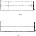
- the amplitude of the signal is proportional to the size of the discontinuity, which enables the use of a fault ranking system when processing signals. It was established experimentally that the dynamic range of the signals constitutes from tens of mV to 10 V. If one eddy-current transducer (2) and a one-channel signal processing unit (3) are used, the signal passes from the receiving coil (6) to the processing and analysis device (3), where it is amplified, supplied to the ADC, converted into a digital code and sent for further processing to the computing device. The results of signal processing are shown in the diagrams in Figs. 3 and 4 .
- Figure 3 shows a diagram of testing the real zone of the electrically conductive object containing faults, in which the amplitude fluctuations of the sensor signal are seen, which indicate the presence of various faults.
- a sharp increase in the signal amplitude reflects the result of the interaction between the eddy currents and the faults in the electrically conductive object.
- Figure 4 shows a diagram of testing a fault-free section of the electrically conductive object, which is practically a straight line, since no variation of AC current generated by eddy current takes place.
- the reason for this is that in the conductor containing no superficial or internal faults, any two arbitrarily chosen sections are similar to each other, in which case eddy currents in the electrically conductive object have a steady-state nature and generate an opposing magnetic field, which does not vary with time and is similar to the constant field of a permanent magnet.
- FIG.5 An example of such a practical implementation is shown in Fig.5 .
- the device comprises at least one pair of eddy-current transducers, each having its own constant-field inductor (5) and its own receiving coil (6) ( Fig. 2 ) spaced apart from each other. This distance may vary from few centimetres to several decimetres.
- the eddy-current transducers sequentially pass along the fault and, as a result of eddy currents interaction with the fault, an ENF change occurs in the receiving coils thereof.
- the EMF in the receiving coils can also be caused by oscillations of the electrically conductive object or eddy-current transducers in the direction of the vibration vector ( Fig. 5 ).
- the signals from the receiving coils of the eddy-current transducers (6a) and (6b) are respectively fed to the preamplifier (7) and preamplifier-inverter (8) located inside the processing and analysis unit (3) and further to the totaliser (9).
- the signals are subject to addition. From the output of the totaliser, the signal is fed to the ADC (10) and, after digitization, to the computing device (11).
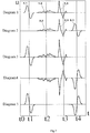
- Fig. 7 shows the signal diagrams explaining the operating principle of the processing and analysis unit.
- Diagrams 1 and 2 contain the following information:
- Diagram 4 shows the same fault- and vibration-generated signals, as well as interference signals from the output of the amplifier-inverter (8), which are fed to the second input of the totaliser (9).
- the following designations are used in the diagrams: U -signal amplitude, t - time axis.
- the vibration- and interference-generated signals are synchronous and inverse with respect to each other, while the fault-generated signals are also inverse with respect to each other, but they are not synchronous and are separated in time from each other by (t4 - tl).
- t4 - tl After adding up such signals by the totaliser (9), a resulting signal is produced at its output, which is fed to the input of the ADC (10) shown in diagram 5.
- the proposed technology which utilises the differential-time processing method and the modified design of the sensor embodied in the form of coupled eddy-current transducers, not only allows to completely eliminate the effect of vibration and external electromagnetic interference on the testing results, but also allows to increase the reliability of testing by obtaining a second signal in addition to the main signal, evidencing the presence of a fault in the tested object, which follows the first signal with a precise time interval of (t4 - tl) and confirms the presence of the fault.
- the signal processing software performs the inversion of the second signal followed by the calculation of the correlation function for both the first and the second signals in order to determine the presence of the fault in the given zone of the tested object.
- Such method of increasing the accuracy of testing and improving the reliability of confirming the fault presence is based on the fact that after the repeated inversion of the second signal, both signals (first and second) become similar to each other, because they are caused by the same fault and are spaced in time due to the time difference at which the coupled first and second eddy-current transducers (2) pass by the fault.
- the value of the latter will be close to unity, which will serve as the evidence of the fact that both eddy-current transducers have registered the same fault.
- the proposed method and device enable the application of the invention for testing of any electrically conductive objects made of different types of materials.
- the possibility of conducting the eddy-current testing with one-way access to the tested object expands the applicability of such method and device.
- the invention can be used in any industry where quality control of the products with complicated access is required, specifically, for controlling rolled sheet and tubular products.
Landscapes
- Chemical & Material Sciences (AREA)
- Chemical Kinetics & Catalysis (AREA)
- Electrochemistry (AREA)
- Physics & Mathematics (AREA)
- Health & Medical Sciences (AREA)
- Life Sciences & Earth Sciences (AREA)
- Analytical Chemistry (AREA)
- Biochemistry (AREA)
- General Health & Medical Sciences (AREA)
- General Physics & Mathematics (AREA)
- Immunology (AREA)
- Pathology (AREA)
- Investigating Or Analyzing Materials By The Use Of Magnetic Means (AREA)
Applications Claiming Priority (2)
| Application Number | Priority Date | Filing Date | Title |
|---|---|---|---|
| RU2015148061A RU2610931C1 (ru) | 2015-11-10 | 2015-11-10 | Способ вихретокового контроля электропроводящих объектов и устройство для его реализации |
| PCT/RU2016/000752 WO2017082770A1 (ru) | 2015-11-10 | 2016-11-07 | Способ вихретокового контроля электропроводящих объектов и устройство для его реализации |
Publications (4)
| Publication Number | Publication Date |
|---|---|
| EP3376216A1 true EP3376216A1 (de) | 2018-09-19 |
| EP3376216A4 EP3376216A4 (de) | 2018-12-05 |
| EP3376216B1 EP3376216B1 (de) | 2023-09-13 |
| EP3376216C0 EP3376216C0 (de) | 2023-09-13 |
Family
ID=58458794
Family Applications (1)
| Application Number | Title | Priority Date | Filing Date |
|---|---|---|---|
| EP16864656.0A Active EP3376216B1 (de) | 2015-11-10 | 2016-11-07 | Verfahren zum wirbelstromtesten von elektrisch leitenden objekten und vorrichtung zur durchführung des besagten verfahrens |
Country Status (3)
| Country | Link |
|---|---|
| EP (1) | EP3376216B1 (de) |
| RU (1) | RU2610931C1 (de) |
| WO (1) | WO2017082770A1 (de) |
Cited By (2)
| Publication number | Priority date | Publication date | Assignee | Title |
|---|---|---|---|---|
| CN110672001A (zh) * | 2019-10-24 | 2020-01-10 | 中航通飞华南飞机工业有限公司 | 一种铁磁性材料表面非铁磁材料厚度测量方法及装置 |
| PL239841B1 (pl) * | 2020-03-10 | 2022-01-17 | Univ West Pomeranian Szczecin Tech | Przetwornik pomiarowy do badania materiałów przewodzących oraz sposób badania materiałów przewodzących |
Families Citing this family (4)
| Publication number | Priority date | Publication date | Assignee | Title |
|---|---|---|---|---|
| RU2651618C1 (ru) * | 2017-04-03 | 2018-04-23 | Общество с ограниченной ответственностью "АльфаСервис" | Способ вихретокового контроля протяжённых электропроводящих объектов и устройство для его реализации |
| RU2665592C1 (ru) * | 2017-09-14 | 2018-08-31 | Общество с ограниченной ответственностью "Энергосервис" (ООО "Энергосервис") | Способ определения местоположения диэлектрического промежутка в электропроводящем объекте и устройство для его осуществления |
| WO2019173768A1 (en) * | 2018-03-08 | 2019-09-12 | Eagle Harbor Technologies, Inc. | Precision eddy current sensor for nondestructive evaluation of structures |
| RU2698557C1 (ru) * | 2019-02-05 | 2019-08-28 | федеральное государственное бюджетное образовательное учреждение высшего образования "Уфимский государственный авиационный технический университет" | Способ вихретокового контроля целостности бандажных оболочек роторов |
Family Cites Families (15)
| Publication number | Priority date | Publication date | Assignee | Title |
|---|---|---|---|---|
| US2519367A (en) * | 1945-07-09 | 1950-08-22 | Gunn Ross | Method of and apparatus for detecting defects in objects |
| US3881151A (en) * | 1974-01-07 | 1975-04-29 | Kennecott Copper Corp | Eddy current flaw detector comprising passing the test piece through an invarient magnetic field gradient and positioning sensor in the gradient |
| US4207519A (en) * | 1978-05-25 | 1980-06-10 | Otdel Fiziki Nerazrusha-Juschego Kontrolya Akademii Nauk Belorusskoi S.S.R. | Method and apparatus for detecting defects in workpieces using a core-type magnet with magneto-sensitive detectors |
| JPS59226858A (ja) * | 1983-06-07 | 1984-12-20 | Sumitomo Metal Ind Ltd | 探傷装置 |
| JPS59650A (ja) * | 1982-06-28 | 1984-01-05 | Hitachi Ltd | ワイヤ−ロ−プの電磁探傷装置 |
| SU1245987A1 (ru) * | 1985-01-11 | 1986-07-23 | Научно-исследовательский институт электронной интроскопии при Томском политехническом институте им.С.М.Кирова | Устройство дл комплексного неразрушающего контрол |
| RU2032898C1 (ru) * | 1992-02-25 | 1995-04-10 | Уральский научно-исследовательский институт трубной промышленности | Способ магнитного контроля дефектов длинномерных ферромагнитных изделий |
| US5610518A (en) * | 1995-03-16 | 1997-03-11 | Eastman Kodak Company | Method and apparatus for detecting small magnetizable particles and flaws in nonmagnetic conductors |
| WO1999028739A1 (en) * | 1997-12-02 | 1999-06-10 | Battelle Memorial Institute | Magnetic induced eddy current inspection method and apparatus |
| JP2001116726A (ja) * | 1999-10-21 | 2001-04-27 | Nkk Corp | 渦流探傷装置 |
| DE102004045271B4 (de) * | 2004-09-17 | 2017-12-28 | Jürgen Rohmann | Verfahren und Vorrichtung zur Detektion von Fehlstellen eines Prüfkörpers aus ferromagnetischem Material |
| GB2475314B8 (en) * | 2009-11-16 | 2013-09-25 | Innospection Group Ltd | Remote environment inspection apparatus and method |
| JP4905560B2 (ja) * | 2010-01-14 | 2012-03-28 | トヨタ自動車株式会社 | 渦流計測用センサ、及び、渦流計測用センサによる検査方法 |
| DE102012017871A1 (de) * | 2012-09-06 | 2014-03-06 | Institut Dr. Foerster Gmbh & Co. Kg | Differentieller Sensor und Verfahren zur Detektion von Anomalien in elektrisch leitfähigen Materialien |
| RU2542624C1 (ru) * | 2014-03-12 | 2015-02-20 | Общество с ограниченной ответственностью (ООО) "Чистые технологии СПб" | Способ вихретокового контроля медной катанки и устройство для его реализации |
-
2015
- 2015-11-10 RU RU2015148061A patent/RU2610931C1/ru active
-
2016
- 2016-11-07 EP EP16864656.0A patent/EP3376216B1/de active Active
- 2016-11-07 WO PCT/RU2016/000752 patent/WO2017082770A1/ru not_active Ceased
Cited By (2)
| Publication number | Priority date | Publication date | Assignee | Title |
|---|---|---|---|---|
| CN110672001A (zh) * | 2019-10-24 | 2020-01-10 | 中航通飞华南飞机工业有限公司 | 一种铁磁性材料表面非铁磁材料厚度测量方法及装置 |
| PL239841B1 (pl) * | 2020-03-10 | 2022-01-17 | Univ West Pomeranian Szczecin Tech | Przetwornik pomiarowy do badania materiałów przewodzących oraz sposób badania materiałów przewodzących |
Also Published As
| Publication number | Publication date |
|---|---|
| WO2017082770A1 (ru) | 2017-05-18 |
| EP3376216A4 (de) | 2018-12-05 |
| EP3376216B1 (de) | 2023-09-13 |
| RU2610931C1 (ru) | 2017-02-17 |
| EP3376216C0 (de) | 2023-09-13 |
Similar Documents
| Publication | Publication Date | Title |
|---|---|---|
| EP3376216B1 (de) | Verfahren zum wirbelstromtesten von elektrisch leitenden objekten und vorrichtung zur durchführung des besagten verfahrens | |
| Ali et al. | Review on system development in eddy current testing and technique for defect classification and characterization | |
| Rocha et al. | Magnetic sensors assessment in velocity induced eddy current testing | |
| CN104903717B (zh) | 用于探测导电材料中的异常的微分传感器、检验系统和方法 | |
| US7759931B2 (en) | Device for measuring magnetic impedance | |
| Deng et al. | A permeability-measuring magnetic flux leakage method for inner surface crack in thick-walled steel pipe | |
| CN103238064B (zh) | 淬火深度测定方法以及淬火深度测定装置 | |
| Huang et al. | A novel eddy current method for defect detection immune to lift-off | |
| Janousek et al. | Novel insight into swept frequency eddy-current non-destructive evaluation of material defects | |
| RU2542624C1 (ru) | Способ вихретокового контроля медной катанки и устройство для его реализации | |
| Angani et al. | Differential pulsed eddy current sensor for the detection of wall thinning in an insulated stainless steel pipe | |
| Xu et al. | Damage detection and assessment of broken wires in cables of a bridge based on magnetic flux leakage | |
| Yang et al. | Investigation on time-to-peak feature insensitive to liftoff effect for pulsed eddy current evaluation | |
| JP2012093095A (ja) | 非破壊検査装置及び非破壊検査方法 | |
| Li et al. | Numerical simulations on electromagnetic NDT at high speed | |
| Yu et al. | Sensitivity focusing through coil angle variation in eddy current testing | |
| JP6551885B2 (ja) | 非破壊検査装置及び非破壊検査方法 | |
| Faraj et al. | Investigate of the effect of width defect on eddy current testing signals under different materials | |
| Nagendran et al. | Transient eddy current NDE system based on fluxgate sensor for the detection of defects in multilayered conducting material | |
| Brauer et al. | Defect detection in conducting materials using eddy current testing techniques | |
| Otterbach et al. | Comparison of defect detection limits in Lorentz force eddy current testing and classical eddy current testing | |
| JP6015954B2 (ja) | 電磁誘導型検査装置及び電磁誘導型検査方法 | |
| Stubendeková et al. | Non-destructive testing of conductive material by eddy current air probe based on swept frequency | |
| Khuong et al. | Defect inspection on flat surfaces and weld zones utilizing an FEC sensor and crack signal processing with the MSSA method | |
| JP2016008931A (ja) | 非破壊検査装置および非破壊検査方法 |
Legal Events
| Date | Code | Title | Description |
|---|---|---|---|
| STAA | Information on the status of an ep patent application or granted ep patent |
Free format text: STATUS: THE INTERNATIONAL PUBLICATION HAS BEEN MADE |
|
| PUAI | Public reference made under article 153(3) epc to a published international application that has entered the european phase |
Free format text: ORIGINAL CODE: 0009012 |
|
| STAA | Information on the status of an ep patent application or granted ep patent |
Free format text: STATUS: REQUEST FOR EXAMINATION WAS MADE |
|
| 17P | Request for examination filed |
Effective date: 20180611 |
|
| AK | Designated contracting states |
Kind code of ref document: A1 Designated state(s): AL AT BE BG CH CY CZ DE DK EE ES FI FR GB GR HR HU IE IS IT LI LT LU LV MC MK MT NL NO PL PT RO RS SE SI SK SM TR |
|
| AX | Request for extension of the european patent |
Extension state: BA ME |
|
| A4 | Supplementary search report drawn up and despatched |
Effective date: 20181107 |
|
| RIC1 | Information provided on ipc code assigned before grant |
Ipc: G01N 27/90 20060101AFI20181029BHEP |
|
| DAV | Request for validation of the european patent (deleted) | ||
| DAX | Request for extension of the european patent (deleted) | ||
| STAA | Information on the status of an ep patent application or granted ep patent |
Free format text: STATUS: EXAMINATION IS IN PROGRESS |
|
| 17Q | First examination report despatched |
Effective date: 20210430 |
|
| GRAP | Despatch of communication of intention to grant a patent |
Free format text: ORIGINAL CODE: EPIDOSNIGR1 |
|
| STAA | Information on the status of an ep patent application or granted ep patent |
Free format text: STATUS: GRANT OF PATENT IS INTENDED |
|
| INTG | Intention to grant announced |
Effective date: 20230420 |
|
| GRAS | Grant fee paid |
Free format text: ORIGINAL CODE: EPIDOSNIGR3 |
|
| GRAA | (expected) grant |
Free format text: ORIGINAL CODE: 0009210 |
|
| STAA | Information on the status of an ep patent application or granted ep patent |
Free format text: STATUS: THE PATENT HAS BEEN GRANTED |
|
| AK | Designated contracting states |
Kind code of ref document: B1 Designated state(s): AL AT BE BG CH CY CZ DE DK EE ES FI FR GB GR HR HU IE IS IT LI LT LU LV MC MK MT NL NO PL PT RO RS SE SI SK SM TR |
|
| REG | Reference to a national code |
Ref country code: GB Ref legal event code: FG4D |
|
| REG | Reference to a national code |
Ref country code: CH Ref legal event code: EP |
|
| REG | Reference to a national code |
Ref country code: DE Ref legal event code: R096 Ref document number: 602016082801 Country of ref document: DE |
|
| REG | Reference to a national code |
Ref country code: IE Ref legal event code: FG4D |
|
| U01 | Request for unitary effect filed |
Effective date: 20231011 |
|
| U07 | Unitary effect registered |
Designated state(s): AT BE BG DE DK EE FI FR IT LT LU LV MT NL PT SE SI Effective date: 20231102 |
|
| U20 | Renewal fee for the european patent with unitary effect paid |
Year of fee payment: 8 Effective date: 20231127 |
|
| PG25 | Lapsed in a contracting state [announced via postgrant information from national office to epo] |
Ref country code: GR Free format text: LAPSE BECAUSE OF FAILURE TO SUBMIT A TRANSLATION OF THE DESCRIPTION OR TO PAY THE FEE WITHIN THE PRESCRIBED TIME-LIMIT Effective date: 20231214 |
|
| PG25 | Lapsed in a contracting state [announced via postgrant information from national office to epo] |
Ref country code: RS Free format text: LAPSE BECAUSE OF FAILURE TO SUBMIT A TRANSLATION OF THE DESCRIPTION OR TO PAY THE FEE WITHIN THE PRESCRIBED TIME-LIMIT Effective date: 20230913 Ref country code: NO Free format text: LAPSE BECAUSE OF FAILURE TO SUBMIT A TRANSLATION OF THE DESCRIPTION OR TO PAY THE FEE WITHIN THE PRESCRIBED TIME-LIMIT Effective date: 20231213 Ref country code: HR Free format text: LAPSE BECAUSE OF FAILURE TO SUBMIT A TRANSLATION OF THE DESCRIPTION OR TO PAY THE FEE WITHIN THE PRESCRIBED TIME-LIMIT Effective date: 20230913 Ref country code: GR Free format text: LAPSE BECAUSE OF FAILURE TO SUBMIT A TRANSLATION OF THE DESCRIPTION OR TO PAY THE FEE WITHIN THE PRESCRIBED TIME-LIMIT Effective date: 20231214 |
|
| PG25 | Lapsed in a contracting state [announced via postgrant information from national office to epo] |
Ref country code: IS Free format text: LAPSE BECAUSE OF FAILURE TO SUBMIT A TRANSLATION OF THE DESCRIPTION OR TO PAY THE FEE WITHIN THE PRESCRIBED TIME-LIMIT Effective date: 20240113 |
|
| PG25 | Lapsed in a contracting state [announced via postgrant information from national office to epo] |
Ref country code: ES Free format text: LAPSE BECAUSE OF FAILURE TO SUBMIT A TRANSLATION OF THE DESCRIPTION OR TO PAY THE FEE WITHIN THE PRESCRIBED TIME-LIMIT Effective date: 20230913 |
|
| PG25 | Lapsed in a contracting state [announced via postgrant information from national office to epo] |
Ref country code: SM Free format text: LAPSE BECAUSE OF FAILURE TO SUBMIT A TRANSLATION OF THE DESCRIPTION OR TO PAY THE FEE WITHIN THE PRESCRIBED TIME-LIMIT Effective date: 20230913 Ref country code: RO Free format text: LAPSE BECAUSE OF FAILURE TO SUBMIT A TRANSLATION OF THE DESCRIPTION OR TO PAY THE FEE WITHIN THE PRESCRIBED TIME-LIMIT Effective date: 20230913 Ref country code: IS Free format text: LAPSE BECAUSE OF FAILURE TO SUBMIT A TRANSLATION OF THE DESCRIPTION OR TO PAY THE FEE WITHIN THE PRESCRIBED TIME-LIMIT Effective date: 20240113 Ref country code: ES Free format text: LAPSE BECAUSE OF FAILURE TO SUBMIT A TRANSLATION OF THE DESCRIPTION OR TO PAY THE FEE WITHIN THE PRESCRIBED TIME-LIMIT Effective date: 20230913 Ref country code: CZ Free format text: LAPSE BECAUSE OF FAILURE TO SUBMIT A TRANSLATION OF THE DESCRIPTION OR TO PAY THE FEE WITHIN THE PRESCRIBED TIME-LIMIT Effective date: 20230913 Ref country code: SK Free format text: LAPSE BECAUSE OF FAILURE TO SUBMIT A TRANSLATION OF THE DESCRIPTION OR TO PAY THE FEE WITHIN THE PRESCRIBED TIME-LIMIT Effective date: 20230913 |
|
| PG25 | Lapsed in a contracting state [announced via postgrant information from national office to epo] |
Ref country code: PL Free format text: LAPSE BECAUSE OF FAILURE TO SUBMIT A TRANSLATION OF THE DESCRIPTION OR TO PAY THE FEE WITHIN THE PRESCRIBED TIME-LIMIT Effective date: 20230913 |
|
| REG | Reference to a national code |
Ref country code: DE Ref legal event code: R097 Ref document number: 602016082801 Country of ref document: DE |
|
| REG | Reference to a national code |
Ref country code: CH Ref legal event code: PL |
|
| PG25 | Lapsed in a contracting state [announced via postgrant information from national office to epo] |
Ref country code: MC Free format text: LAPSE BECAUSE OF FAILURE TO SUBMIT A TRANSLATION OF THE DESCRIPTION OR TO PAY THE FEE WITHIN THE PRESCRIBED TIME-LIMIT Effective date: 20230913 |
|
| PG25 | Lapsed in a contracting state [announced via postgrant information from national office to epo] |
Ref country code: CH Free format text: LAPSE BECAUSE OF NON-PAYMENT OF DUE FEES Effective date: 20231130 |
|
| PLBE | No opposition filed within time limit |
Free format text: ORIGINAL CODE: 0009261 |
|
| STAA | Information on the status of an ep patent application or granted ep patent |
Free format text: STATUS: NO OPPOSITION FILED WITHIN TIME LIMIT |
|
| PG25 | Lapsed in a contracting state [announced via postgrant information from national office to epo] |
Ref country code: MC Free format text: LAPSE BECAUSE OF FAILURE TO SUBMIT A TRANSLATION OF THE DESCRIPTION OR TO PAY THE FEE WITHIN THE PRESCRIBED TIME-LIMIT Effective date: 20230913 Ref country code: CH Free format text: LAPSE BECAUSE OF NON-PAYMENT OF DUE FEES Effective date: 20231130 |
|
| 26N | No opposition filed |
Effective date: 20240614 |
|
| GBPC | Gb: european patent ceased through non-payment of renewal fee |
Effective date: 20231213 |
|
| REG | Reference to a national code |
Ref country code: IE Ref legal event code: MM4A |
|
| PG25 | Lapsed in a contracting state [announced via postgrant information from national office to epo] |
Ref country code: IE Free format text: LAPSE BECAUSE OF NON-PAYMENT OF DUE FEES Effective date: 20231107 |
|
| PG25 | Lapsed in a contracting state [announced via postgrant information from national office to epo] |
Ref country code: GB Free format text: LAPSE BECAUSE OF NON-PAYMENT OF DUE FEES Effective date: 20231213 |
|
| PG25 | Lapsed in a contracting state [announced via postgrant information from national office to epo] |
Ref country code: IE Free format text: LAPSE BECAUSE OF NON-PAYMENT OF DUE FEES Effective date: 20231107 Ref country code: GB Free format text: LAPSE BECAUSE OF NON-PAYMENT OF DUE FEES Effective date: 20231213 |
|
| PG25 | Lapsed in a contracting state [announced via postgrant information from national office to epo] |
Ref country code: CY Free format text: LAPSE BECAUSE OF FAILURE TO SUBMIT A TRANSLATION OF THE DESCRIPTION OR TO PAY THE FEE WITHIN THE PRESCRIBED TIME-LIMIT; INVALID AB INITIO Effective date: 20161107 |
|
| U90 | Renewal fees not paid: noting of loss of rights |
Free format text: RENEWAL FEE NOT PAID FOR YEAR 09 Effective date: 20250709 |
|
| PG25 | Lapsed in a contracting state [announced via postgrant information from national office to epo] |
Ref country code: HU Free format text: LAPSE BECAUSE OF FAILURE TO SUBMIT A TRANSLATION OF THE DESCRIPTION OR TO PAY THE FEE WITHIN THE PRESCRIBED TIME-LIMIT; INVALID AB INITIO Effective date: 20161107 |
|
| U93 | Unitary patent lapsed |
Free format text: RENEWAL FEE NOT PAID Effective date: 20241130 |
|
| PG25 | Lapsed in a contracting state [announced via postgrant information from national office to epo] |
Ref country code: TR Free format text: LAPSE BECAUSE OF FAILURE TO SUBMIT A TRANSLATION OF THE DESCRIPTION OR TO PAY THE FEE WITHIN THE PRESCRIBED TIME-LIMIT Effective date: 20230913 |