EP3376129A2 - Wall feedthrough for connection to a domestic appliance and method for fitting a wall feedthrough - Google Patents
Wall feedthrough for connection to a domestic appliance and method for fitting a wall feedthrough Download PDFInfo
- Publication number
- EP3376129A2 EP3376129A2 EP18160083.4A EP18160083A EP3376129A2 EP 3376129 A2 EP3376129 A2 EP 3376129A2 EP 18160083 A EP18160083 A EP 18160083A EP 3376129 A2 EP3376129 A2 EP 3376129A2
- Authority
- EP
- European Patent Office
- Prior art keywords
- guide body
- fluid
- fluid guide
- wall
- opening
- Prior art date
- Legal status (The legal status is an assumption and is not a legal conclusion. Google has not performed a legal analysis and makes no representation as to the accuracy of the status listed.)
- Granted
Links
- 238000000034 method Methods 0.000 title claims description 6
- 239000012530 fluid Substances 0.000 claims abstract description 168
- 238000007789 sealing Methods 0.000 claims description 13
- 238000009434 installation Methods 0.000 claims description 10
- 238000000926 separation method Methods 0.000 claims description 6
- 238000003780 insertion Methods 0.000 claims description 5
- 230000037431 insertion Effects 0.000 claims description 5
- 238000010276 construction Methods 0.000 claims description 4
- 238000009413 insulation Methods 0.000 description 9
- 239000000463 material Substances 0.000 description 9
- 238000010521 absorption reaction Methods 0.000 description 5
- 230000002093 peripheral effect Effects 0.000 description 5
- 239000004794 expanded polystyrene Substances 0.000 description 4
- 238000004519 manufacturing process Methods 0.000 description 4
- 239000011505 plaster Substances 0.000 description 4
- 238000009423 ventilation Methods 0.000 description 4
- 230000035515 penetration Effects 0.000 description 3
- XLYOFNOQVPJJNP-UHFFFAOYSA-N water Substances O XLYOFNOQVPJJNP-UHFFFAOYSA-N 0.000 description 3
- 239000004743 Polypropylene Substances 0.000 description 2
- 239000000853 adhesive Substances 0.000 description 2
- 230000001070 adhesive effect Effects 0.000 description 2
- 238000010586 diagram Methods 0.000 description 2
- 239000002184 metal Substances 0.000 description 2
- 238000005192 partition Methods 0.000 description 2
- -1 polypropylene Polymers 0.000 description 2
- 229920001155 polypropylene Polymers 0.000 description 2
- 239000000565 sealant Substances 0.000 description 2
- 229920000426 Microplastic Polymers 0.000 description 1
- 230000006978 adaptation Effects 0.000 description 1
- 230000006835 compression Effects 0.000 description 1
- 238000007906 compression Methods 0.000 description 1
- 238000009833 condensation Methods 0.000 description 1
- 230000005494 condensation Effects 0.000 description 1
- 230000001419 dependent effect Effects 0.000 description 1
- 238000005516 engineering process Methods 0.000 description 1
- 238000002347 injection Methods 0.000 description 1
- 239000007924 injection Substances 0.000 description 1
- 239000011810 insulating material Substances 0.000 description 1
- 230000000149 penetrating effect Effects 0.000 description 1
- 239000004033 plastic Substances 0.000 description 1
- 229920003023 plastic Polymers 0.000 description 1
- 229920001296 polysiloxane Polymers 0.000 description 1
- 230000035945 sensitivity Effects 0.000 description 1
- 230000006641 stabilisation Effects 0.000 description 1
- 238000011105 stabilization Methods 0.000 description 1
- 229920001169 thermoplastic Polymers 0.000 description 1
- 239000004416 thermosoftening plastic Substances 0.000 description 1
- 230000007704 transition Effects 0.000 description 1
Images

Classifications
-
- F—MECHANICAL ENGINEERING; LIGHTING; HEATING; WEAPONS; BLASTING
- F24—HEATING; RANGES; VENTILATING
- F24F—AIR-CONDITIONING; AIR-HUMIDIFICATION; VENTILATION; USE OF AIR CURRENTS FOR SCREENING
- F24F13/00—Details common to, or for air-conditioning, air-humidification, ventilation or use of air currents for screening
- F24F13/02—Ducting arrangements
- F24F13/0272—Modules for easy installation or transport
-
- F—MECHANICAL ENGINEERING; LIGHTING; HEATING; WEAPONS; BLASTING
- F24—HEATING; RANGES; VENTILATING
- F24F—AIR-CONDITIONING; AIR-HUMIDIFICATION; VENTILATION; USE OF AIR CURRENTS FOR SCREENING
- F24F13/00—Details common to, or for air-conditioning, air-humidification, ventilation or use of air currents for screening
- F24F13/02—Ducting arrangements
- F24F13/0209—Ducting arrangements characterised by their connecting means, e.g. flanges
-
- F—MECHANICAL ENGINEERING; LIGHTING; HEATING; WEAPONS; BLASTING
- F24—HEATING; RANGES; VENTILATING
- F24F—AIR-CONDITIONING; AIR-HUMIDIFICATION; VENTILATION; USE OF AIR CURRENTS FOR SCREENING
- F24F7/00—Ventilation
- F24F2007/0025—Ventilation using vent ports in a wall
-
- F—MECHANICAL ENGINEERING; LIGHTING; HEATING; WEAPONS; BLASTING
- F24—HEATING; RANGES; VENTILATING
- F24F—AIR-CONDITIONING; AIR-HUMIDIFICATION; VENTILATION; USE OF AIR CURRENTS FOR SCREENING
- F24F2221/00—Details or features not otherwise provided for
- F24F2221/17—Details or features not otherwise provided for mounted in a wall
Definitions
- the present invention relates to a wall bushing for connection to a building services equipment, in particular an internally deployable heat pump or a ventilation device and a method for mounting the wall feedthrough.
- Home technology devices in particular air-water heat pumps or central ventilation devices that are installed within buildings require a wall outlet to the outside through which the required supply air can be supplied and the exhaust air can be discharged.
- a fluid line to the heat pump or the central ventilation unit is provided and attached the other end to a wall duct.
- flexible systems are known as sheet metal structures with thermal insulation mats in the market in length, which can be adapted telescopically to the wall thickness of the house.
- the final wall thickness is often known only at a later date, when the insulation of the facade and the final exterior plaster are applied to the shell.
- a correct installation and positioning of the wall duct in the opening of the building wall can only be carried out at a later time.
- a wall duct for guiding the air, which can be used in an opening of a building wall.
- the wall bushing is constructed in several parts and consists of at least two parts, a first fluid guide body and a second fluid guide body, which fit from an inner side and / or an outer side into the opening of the building wall and are telescopically or telescopically slidable.
- the first fluid guide body has at an inner opening a receptacle for connecting a fluid line of a home automation device and the second fluid guide body has at an outer opening to the outside air.
- the first fluid guide body and the second fluid guide body in the installed state are at least partially overlapping and have an internal connection point.
- the second fluid guide body abuts with its second slot on at least one wall of the first fluid guide body.
- the embodiment of the wall bushing according to the invention allows flexible adaptation to different wall thicknesses of a building, such as in a wooden stand construction, massive masonry, walls with external thermal insulation in different thicknesses and plastered and / or verklinkerten exterior walls.
- the first fluid guide body of the wall duct is preferably designed at least partially double-walled and has a guide space arranged radially to a longitudinal axis, advantageously in the form of a groove, in which the second fluid guide body can be inserted and / or guided.
- the second fluid guide body rests with its second slot in the guide space in particular on a guide and / or on a first jacket.
- the guide space preferably has a spacing which is designed such that a firm seat is formed when the first and second fluid guide bodies are pushed together.
- the guide space may have a round, wavy, angular, triangular, quadrangular or polygonal shape, in which the second and / or a third fluid guide body is immersed and guided.
- a further feature of the invention is that the first fluid guide body has a flow cross-section which increases in size in the longitudinal direction of the wall passage from the inner opening to the outer opening.
- the flow cross section at the inner opening is smaller than the flow cross section at a leading end of the first fluid guide body. Further advantageously, the flow cross section at the inner opening is smaller than the flow cross section at the outer opening of the second fluid guide body. Preferably, the flow cross section at the inner opening is smaller than the flow cross section at an insertion end of the second fluid guide body. Further advantageously, the flow cross section at the leading end is smaller than the flow cross section at the insertion end.
- the inventive design of the inner contour with a slope from the inner opening to the outer opening of the wall bushing is used in particular to the fact that optionally moisture, in particular incoming water, can easily run off, in particular to the outside.
- the first and the second fluid guide body is advantageously formed symmetrically, in particular about rotations between 0 degrees and 90 degrees and / or 90 degrees and 180 degrees and / or 180 degrees and 270 degrees with respect to the Wandnormalen perpendicular to the building wall is to run.
- the gradient is advantageously independent of the orientation during installation of the wall feedthrough.
- the invention formed by the inner opening to the outer opening towards the slope that even with an installation of a slightly sloping to the inside wall penetration secure drainage of moisture is ensured to the outside.
- the wall bushing additionally has a third fluid guide body, which preferably serves as a temporary installation aid, in particular during the plastering work and when applying the thermal insulation, and acts as a placeholder in place of the final second fluid guide body.
- the assembly aid or the third fluid guide body has an outer geometry which is identical or at least partially identical over the entire length of the third fluid guide body with the outer geometry of the second fluid guide body.
- the outer geometry of the third fluid guide body can be made slightly larger than that of the second fluid guide body.
- the third fluid guide body advantageously has a removable fluid partition wall.
- an opening as a passage from the fluid partition wall are separated out.
- the third fluid guide body advantageously has a third jacket, which is designed to be longer in length than the second jacket of the second fluid guide body for attachment of the surface and / or the thermal insulation. Due to the longer third mantle this stands out with the peripheral edge of the opening of the building wall.
- the third fluid guide body of the wall duct until the completion of the wall structure including the plaster work at the location of the second fluid guide body in the opening of the building wall, in particular in the guide space of the first fluid guide body, remain. Only then, when the final state is reached, the third fluid guide body can be removed from the opening of the building wall and replaced or replaced by the second fluid guide body,
- first, second and / or third fluid guide body are advantageously formed of a heat-insulating material.
- a heat-insulating material Preferably, in particular expanded polystyrene (EPS) or expanded polypropylene (EPP) can be used for the production of the wall feedthrough.
- EPS and / or EPP is advantageous because the use of an occurring condensation in or on the masonry is prevented.
- expanded thermoplastics have high strength, stability and robustness, in particular with correspondingly high bulk density.
- plastic granules can be dyed dark or at least partially dark in their manufacture.
- a low or at least a partially lower sensitivity to dirt of the wall feedthrough is generated.
- the fluid guide bodies are especially painted on the inside in order to facilitate drainage of water. Thus, icing is prevented.
- a sealing means between the first and the second fluid guide body for connection and / or sealing against fluid is applied or attachable.
- the sealing means is arranged on at least one internal connection point, on a seam, in particular in a joint area, circumferentially between the first and second fluid guide body.
- the sealant should prevent moisture from entering the masonry and causing damage there.
- sealing means is preferably attachable to the inner surface of the peripheral edge of the second fluid guide body to connect the wall duct with the building wall.
- At least one expansion sealing tape, compression band, silicone, rubber seals and / or adhesive may be used as the sealant.
- sealing rings or lip seals can be used.
- another commercially available sealing means can be used, which in particular ensures a fluid-tight connection to possible openings, cold bridges or weak points.
- the seal may be completely circumferential or even formed only in the lower region of the wall duct where moisture could possibly occur.
- the third fluid guide body and / or the second fluid guide body are designed such that a fluid-carrying cover device can be attached to the respective outer opening or at least temporarily provisionally fastened.
- the second fluid guide body for final attachment of the fluid-carrying cover at least one fastening device.
- fastening means nails, screws or the like can be used to attach the fluid-carrying cover device to the second and / or third fluid guide body.
- the fastening device is foamed in the production of the second fluid guide body to the outer opening, in particular in the peripheral edge, with.
- the first fluid guide body on the inner opening, in particular on the inside of the building wall preferably a receptacle for connecting a fluid line of the building services device, in particular an internally deployable heat pump or a ventilation device comprises.
- the fluid line can be connected to the receptacle and fastened by fastening means to the outer opening of the first fluid guide body.
- the pre-assembled with the fluid line spigot is connected by plugging and screwing to the inner opening.
- the separate connecting piece preferably has a cylindrical or at least one elliptical shape and is preferably made of EPS, EPP, as a plastic injection molded part or of metal.
- connection piece As fastening means of the connecting piece to the wall bushing screws are used, which are screwed into threaded nuts in the wall bushing, in particular in the first fluid guide body. Furthermore, clamping connections such as clamps, adhesives or other commercially available fastening means can be used for this purpose.
- the sealing of the connection piece takes place in particular by means of sealing tape.
- the wall bushing preferably has at least two absorption elements for noise reduction in the interior.
- the absorption elements are in particular made of the same material as that of the wall leadthrough.
- the absorption elements may be made of a different material.
- the wall bushing on absorption elements which are arranged along or at least partially along the longitudinal axis of each other and spaced from each other.
- the absorption elements can be arranged vertically spaced from one another longitudinally of the longitudinal axis and also have openings for air passage.
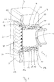
- Fig. 1 shows a sectional view of a wall duct with a first and second fluid guide body according to the invention.
- the wall bushing 1 is designed in several parts and has a first fluid guide body 10 and a second fluid guide body 20.
- the first fluid guide body 10 preferably has a guide 13, a first jacket 15, a guide space 12 and a receptacle 16 on its inner opening 11.
- the second fluid guide body 20 preferably has a second insert 22, a second jacket 25 and a peripheral second edge 26 at its outer opening 21.
- the second fluid guide body 20 can be introduced into the first fluid guide body 10, in particular into the guide space 12, and lies with an inner surface 24 of the second rim 26 preferably flat or flush on the outer side 5 of the building wall 3.
- the second fluid guide body 20 preferably has at its outer opening 21 a fluid-conducting cover device 40, which can be fastened to the second edge 26.
- an overlap region 60 partially forms between the second insert 22 and the guide 13 and / or the first jacket 15.
- the first fluid guide body 10 can be inserted into the second fluid guide body 20, whereby a closure in the overlap region 60 or at least partially made.
- the second insert 22 of the second fluid guide body 20 is preferably at most as long as the guide 13 of the first fluid guide body 10 is formed.
- the second slot 22 may be slightly shorter than the guide 13 may be formed when applied to the building wall 3 surface and / or Thermal insulation should have a smaller thickness. Incidentally, by a shorter execution of the second insert 22 material costs can be saved.
- the double wall of the first fluid guide body 10, which is formed in particular by the guide 13 and the first jacket 15, serves to form a stable connection between the two fluid guide bodies 10, 20 in an opening 2 of the building wall 3.
- the second shell 25 of the second fluid guide body 20 has a length which corresponds to the thickness of the surface and / or the thermal insulation on the building wall 3 or mostly.
- the first and second fluid guide body 10, 20 have a material thickness between 10 mm and 100 mm, in particular between 10 mm and 50 mm.
- first and second fluid guide bodies 10, 20 of the wall duct 1 preferably have square dimensions.
- first and second fluid guide body 10, 20 along a longitudinal axis 70 may also be made round.
- first and second fluid guide bodies 10, 20 may be rectangular, with an aspect ratio between 1: 1 and / or 1: 2.5.
- the first fluid guide body 10 has an outer geometry that adapts to the geometry of the opening in the building wall. Furthermore, the first fluid guide body 10 has an inner contour with an aerodynamic shape for optimum air guidance.
- the first fluid guide body 10 of the wall duct 1 is inserted from the inside 4 of the building wall 3 into the opening 2.
- the first fluid guide body 10 can be introduced from the outside 5 of the building wall 3 into the opening 2.
- the second fluid guide body 20 and / or a third fluid guide body (in Fig. 1 not shown) is preferably inserted from the outside 5 in the opening 2.
- first the first fluid guide body 10 and then the second fluid guide body 20 is inserted into the opening 2 of the building wall 3. If the final wall structure has not yet been reached, instead of the second fluid guide body 20, the third fluid guide body 30 is advantageously first inserted into the opening of the building wall 3 as a mounting aid.
- the third fluid guide body 30 can be used simultaneously with the first fluid guide body in the opening.
- the third fluid guide body can be timed before or after the time Insertion of the first fluid guide body 10 are inserted.
- the second fluid guide body 20 can be inserted into the opening 2 in time before the first fluid guide body 10 or at the same time as the first fluid guide body 10.
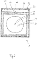
- Fig. 2 shows the front view of the second fluid guide body in the installed state according to Fig. 1 in a sketched schematic representation.
- the preferably square or rectangular wall duct 1 has different body edges.
- the second fluid guide body 20 is framed by the circumferential second edge 26 at the outer opening 21, to which the fluid-carrying cover device 40 can be fastened (in Fig. 2 not shown, but eg in Fig. 1 and Fig. 3 ).
- the outer opening 21 has the largest flow cross section A4.
- the second insert 22 is advantageously framed and / or bounded by a first jacket 15 and / or a guide 13, which has a flow cross-section A2. Since the first jacket 15 of the first fluid guide body 10 is not visible in the front view, are in Fig. 2 the hidden edges are shown in dashed lines.
- the inner opening 11 of the first fluid guide body 10 is preferably round and has over the multi-part wall duct 1, the smallest flow area A1.
- the transition of the rectangular or at least partially rectangular flow cross section to a round or at least partially round flow cross section serves to arrange a rectangular fluid-conducting cover device 40 on the outer opening 21 and a fluid line 6 of round cross section on the inner opening 11.
- first and second fluid guide body 10, 20 may be formed radially over the entire length of the wall duct 1 oval, in particular round.
- the embodiment according to the invention of a flow cross-section (A1-A4) which increases from the inner opening 11 to the outer opening 21 preferably serves to allow any condensate occurring inside the wall duct or penetrating moisture, such as driving rain, to drain easily from the outside at the outer opening.
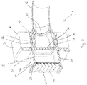
- Fig. 3 shows a sectional view of a wall duct consisting of a first and a third fluid guide body.
- the third fluid guide body 30 has a third one Sheath 35 on, which has a greater length than the second sheath 25, as in Fig. 1 shown.
- the plaster and / or the thermal insulation can be applied to the intended locations on the building wall 3 without restriction on a longer third shell 35.
- the third guide body 30 has a removable fluid separation wall 36, which is preferably formed on a base 37.
- the fluid separation wall 36 is disposed at the level of the outside 5 of the building wall 3.
- the closed supporting fluid separation wall 36 in the interior of the third fluid guide body 30 a stabilization and support of the wall bushing 1 is preferably achieved against deformations in the radial direction. Furthermore, the fluid separation wall 36 serves in particular to prevent an air passage through the wall duct 1, in particular in the installation phase of the wall duct 1. Optionally, the fluid separation wall 36 can be cut out, if a temporary air passage through the wall duct 1 is temporarily desired.
- the first and third fluid guide body 10, 30 preferably have a material thickness between 10 mm and 100 mm, in particular between 10 mm and 50 mm.
- Fig. 4 shows a schematic diagram of a fastening device for connecting the fluid-carrying cover to the outer opening.
- the fastening device 41 preferably has a basic framework 42, in particular in the form of an angle plate with at least one sleeve 43.
- the skeleton 42 preferably tensions an angle that corresponds or partially corresponds to the geometry of the second edge 26 and / or the second shell 25 (see FIG Fig. 1 ).
- the fastening device 41 is disposed in or on the second edge 26 of the second fluid guide body 20 and serves to receive and attach the fluid-carrying cover 40 at the outer opening 21.
- the skeleton 42 of the fastening device 41 with at least one sleeve 43 already in the manufacture of second fluid guide body 20 inserted into the second edge 26 of the second fluid guide body 20.
- the end 44 of the sleeve 43 is flush with the outer surface 27 of the second edge 26 from.
- the sleeve 43 is a threaded sleeve having an internal thread.
- the sleeve 43 designed as a threaded pin with external thread and protrudes for attachment with a fastener outside the outer surface 27 of the second edge 26 out.
- the sleeve 43 has a length which preferably corresponds to the material thickness of the second edge 26.
- the skeleton 42 is designed as a lightweight variant with recesses in the material.
- the number of required fastening devices - depending on the design of the second fluid guide body 20 - vary.
- at least two fastening devices are needed.
- four fastening devices can be used.
- longer angle plates with at least one sleeve, in particular two, preferably four, sleeves can be used in order to produce a uniform fit between the fluid-carrying cover device 40 and the second edge 26 of the second fluid guide body 20.
- the fastening device 41 may advantageously be formed from a one-piece round angle plate with at least two threaded sleeves.
- the round angle plate can be constructed in two parts or in several parts.
Abstract
Die Erfindung betrifft eine Wanddurchführung (1) zum Führen von Luft, die in eine Öffnung (2) einer Gebäudewand (3) einsetzbar ist. Die Wanddurchführung (1) besteht aus mindestens zwei Teilen, einem ersten Fiuidführungskörper (10) mit einer Innenöffnung (11) zum Anschluss einer Fluidleitung (6) eines Haustechnikgerätes und einem zweiten Fluidführungskärper (20) mit einer Außenöffnung (21), die eine Verbindung zur Außenluft aufweist. Der erste fluidführungskörper (10) und der zweite Fluidführungskörper (20) sind im Einbauzustand zumindest teilweise überlappend ausgebildet und der erste Fluidführungskörper (10) weist einen von der Innenöffnung (11) zur Außenöffnung (21) hin sich vergrößernden Strömungsquerschnitt (A1-A4) auf.The invention relates to a wall duct (1) for guiding air which can be inserted into an opening (2) of a building wall (3). The wall bushing (1) consists of at least two parts, a first Fiuidführungskörper (10) with an inner opening (11) for connecting a fluid line (6) of a building services device and a second Fluidführungskärper (20) with an outer opening (21) which connects to Outside air has. The first fluid guide body (10) and the second fluid guide body (20) are at least partially overlapping in the installed state and the first fluid guide body (10) has a from the inner opening (11) to the outer opening (21) towards increasing flow cross-section (A1-A4) ,
Description
Die vorliegende Erfindung betrifft eine Wanddurchführung zum Anschluss an ein Haustechnikgerät, insbesondere eine innen aufstellbare Wärmepumpe oder eines Lüftungsgerätes und ein Verfahren zur Montage der Wanddurchführung.The present invention relates to a wall bushing for connection to a building services equipment, in particular an internally deployable heat pump or a ventilation device and a method for mounting the wall feedthrough.
Haustechnikgeräte, insbesondere Luft-Wasser-Wärmepumpen oder zentrale Lüftungsgeräte, die innerhalb von Gebäuden aufgestellt werden, benötigen eine Wanddurchführung nach außen, durch die die benötigte Zuluft zugeführt und die Abluft abgeführt werden kann. Hierzu wird wenigstens ein Ende einer Fluidleitung an der Wärmepumpe oder dem zentralen Lüftungsgerät vorgesehen und das andere Ende an einer Wanddurchführung befestigt.Home technology devices, in particular air-water heat pumps or central ventilation devices that are installed within buildings require a wall outlet to the outside through which the required supply air can be supplied and the exhaust air can be discharged. For this purpose, at least one end of a fluid line to the heat pump or the central ventilation unit is provided and attached the other end to a wall duct.
Aus dem Stand der Technik sind Wanddurchführungen als starre Systeme, insbesondere Rohr-Systeme, aus expandiertem Polystyrol (EPS) oder expandiertem Polypropylen (EPP) oder Kanäle bekannt. Derartige Wanddurchführungen haben eine Standardlänge, die beim Einbau auf die entsprechende Wandstärke gekürzt werden müssen.From the prior art wall penetrations as rigid systems, in particular pipe systems, made of expanded polystyrene (EPS) or expanded polypropylene (EPP) or channels known. Such wall penetrations have a standard length, which must be reduced during installation to the appropriate wall thickness.
Zudem sind in der Länge flexible Systeme als Blechkonstruktionen mit Wärmedämmmatten im Markt bekannt, die sich teleskopartig an die Wanddicke des Hauses anpassen lassen. Insbesondere bei Neubauten ist die endgültige Wandstärke oft erst zu einem späteren Zeitpunkt bekannt, wenn die Wärmedämmung der Fassade und der abschließende Außenputz auf dem Rohbau aufgetragen sind. Dadurch ist eine korrekte Montage und Positionierung der Wanddurchführung in der Öffnung der Gebäudewand erst zu einem späteren Zeitpunkt durchführbar.In addition, flexible systems are known as sheet metal structures with thermal insulation mats in the market in length, which can be adapted telescopically to the wall thickness of the house. Especially in new buildings, the final wall thickness is often known only at a later date, when the insulation of the facade and the final exterior plaster are applied to the shell. As a result, a correct installation and positioning of the wall duct in the opening of the building wall can only be carried out at a later time.
Es ist daher eine Aufgabe der vorliegenden Erfindung, eine Wanddurchführung zum Anschluss an ein Haustechnikgerät vorzusehen, welche eine einfachere und komfortablere Montage in Gebäudewänden mit unterschiedlichsten Wandaufbauten sowohl in der Bau- und Installationsphase als auch nach Fertigstellung des Wandaufbaus ermöglicht, ohne dass eine mechanische Bearbeitung der Wanddurchführung vor Ort notwendig ist.It is therefore an object of the present invention to provide a wall bushing for connection to a home automation device, which allows a simpler and more comfortable installation in building walls with a variety of wall structures both in the construction and installation phase and after completion of the wall structure, without any mechanical processing of Wall feedthrough on site is necessary.
Diese Aufgabe wird durch eine Wanddurchführung nach Anspruch 1 gelöst. Ein Verfahren zur Montage der Wanddurchführung löst die Aufgabe entsprechend Anspruch 8. Vorteilhafte Ausführungen der Erfindung sind in den Unteransprüchen angegeben.This object is achieved by a wall duct according to
Vorgesehen ist eine Wanddurchführung zum Führen der Luft, die in eine Öffnung einer Gebäudewand einsetzbar ist. Die Wanddurchführung ist mehrteilig aufgebaut und besteht aus mindestens zwei Teilen, einem ersten Fluidführungskörper und einem zweiten Fluidführungskörper, die von einer Innenseite und/oder einer Außenseite in die Öffnung der Gebäudewand passen und ineinander schiebbar oder teleskopartig ineinander schiebbar sind. Der erste Fluidführungskörper weist an einer Innenöffnung eine Aufnahme zum Anschluss einer Fluidleitung eines Haustechnikgerätes auf und der zweite Fluidführungskörper weist an einer Außenöffnung eine Verbindung zur Außenluft auf.Provided is a wall duct for guiding the air, which can be used in an opening of a building wall. The wall bushing is constructed in several parts and consists of at least two parts, a first fluid guide body and a second fluid guide body, which fit from an inner side and / or an outer side into the opening of the building wall and are telescopically or telescopically slidable. The first fluid guide body has at an inner opening a receptacle for connecting a fluid line of a home automation device and the second fluid guide body has at an outer opening to the outside air.
Erfindungsgemäß sind der erste Fluidführungskörper und der zweite Fluidführungskörper im Einbauzustand zumindest teilweise überlappend ausgebildet und weisen eine interne Verbindungsstelle auf. Vorzugsweise liegt der zweite Fluidführungskörper mit seinem zweiten Einschub an mindestens einer Wandung des ersten Fluidführungskörpers an. Die erfindungsgemäße Ausgestaltung der Wanddurchführung ermöglicht eine flexible Anpassung an unterschiedliche Wanddicken eines Gebäudes, so beispielsweise bei einem Holzständerbau, bei einem massiven Mauerwerk, bei Wänden mit externer Wärmedämmung in unterschiedlichen Dicken sowie bei verputzten und/oder verklinkerten Außenwänden.According to the invention, the first fluid guide body and the second fluid guide body in the installed state are at least partially overlapping and have an internal connection point. Preferably, the second fluid guide body abuts with its second slot on at least one wall of the first fluid guide body. The embodiment of the wall bushing according to the invention allows flexible adaptation to different wall thicknesses of a building, such as in a wooden stand construction, massive masonry, walls with external thermal insulation in different thicknesses and plastered and / or verklinkerten exterior walls.
Weiterhin ist der erste Fluidführungskörper der Wanddurchführung vorzugsweise zumindest teilweise doppelwandig ausgestaltet und weist einen radial zu einer Längsachse angeordneten Führungsraum, vorteilhafterweise in Form einer Nut, auf, in dem der zweite Fluidführungskörper einführbar und/oder führbar ist. Vorteilhafterweise liegt der zweite Fluidführungskörper mit seinem zweiten Einschub im Führungsraum insbesondere an einer Führung und/oder an einem ersten Mantel an. Der Führungsraum weist vorzugsweise einen Abstand auf, der derart ausgestaltet ist, damit sich beim Zusammenschieben der ersten und zweiten Fluidführungskörper ein fester Sitz ausbildet.Furthermore, the first fluid guide body of the wall duct is preferably designed at least partially double-walled and has a guide space arranged radially to a longitudinal axis, advantageously in the form of a groove, in which the second fluid guide body can be inserted and / or guided. Advantageously, the second fluid guide body rests with its second slot in the guide space in particular on a guide and / or on a first jacket. The guide space preferably has a spacing which is designed such that a firm seat is formed when the first and second fluid guide bodies are pushed together.
Optional kann der Führungsraum eine runde, wellenförmige, eckige, dreieckige, viereckige oder mehreckige Form aufweisen, in den der zweite und/oder ein dritter Fluidführungskörper eintaucht und geführt wird.Optionally, the guide space may have a round, wavy, angular, triangular, quadrangular or polygonal shape, in which the second and / or a third fluid guide body is immersed and guided.
Ein weiteres Merkmal der Erfindung ist, dass der erste Fluidführungskörper einen von der Innenöffnung zur Außenöffnung hin sich vergrößernden Strömungsquerschnitt in Längsrichtung der Wanddurchführung aufweist.A further feature of the invention is that the first fluid guide body has a flow cross-section which increases in size in the longitudinal direction of the wall passage from the inner opening to the outer opening.
Vorzugsweise ist der Strömungsquerschnitt an der Innenöffnung kleiner als der Strömungsquerschnitt an einem Führungsende des ersten Fluidführungskörpers. Weiterhin vorteilhaft ist der Strömungsquerschnitt an der Innenöffnung kleiner als der Strömungsquerschnitt an der Außenöffnung des zweiten Fluidführungskörpers. Vorzugsweise ist der Strömungsquerschnitt an der Innenöffnung kleiner als der Strömungsquerschnitt an einem Einschubende des zweiten Fluidführungskörpers. Weiterhin vorteilhaft ist der Strömungsquerschnitt an dem Führungsende kleiner als der Strömungsquerschnitt an dem Einschubende.Preferably, the flow cross section at the inner opening is smaller than the flow cross section at a leading end of the first fluid guide body. Further advantageously, the flow cross section at the inner opening is smaller than the flow cross section at the outer opening of the second fluid guide body. Preferably, the flow cross section at the inner opening is smaller than the flow cross section at an insertion end of the second fluid guide body. Further advantageously, the flow cross section at the leading end is smaller than the flow cross section at the insertion end.
Die erfindungsgemäße Gestaltung der Innenkontur mit einem Gefälle von der Innenöffnung zur Außenöffnung der Wanddurchführung dient insbesondere dazu, dass gegebenenfalls Feuchtigkeit, insbesondere eintretendes Wasser, leicht ablaufen kann, insbesondere nach außen.The inventive design of the inner contour with a slope from the inner opening to the outer opening of the wall bushing is used in particular to the fact that optionally moisture, in particular incoming water, can easily run off, in particular to the outside.
Zur Vermeidung einer falschen Orientierung beim Einbau der Wanddurchführung ist der erste und der zweite Fluidführungskörper vorteilhafterweise symmetrisch ausgebildet, insbesondere um Drehungen zwischen 0 Grad und 90 Grad und/oder 90 Grad und 180 Grad und/oder 180 Grad und 270 Grad bezüglich der Wandnormalen, die senkrecht zur Gebäudewand liegt, ausführen zu können.To avoid incorrect orientation when installing the wall bushing, the first and the second fluid guide body is advantageously formed symmetrically, in particular about rotations between 0 degrees and 90 degrees and / or 90 degrees and 180 degrees and / or 180 degrees and 270 degrees with respect to the Wandnormalen perpendicular to the building wall is to run.
Durch den vorzugsweise symmetrischen Aufbau der Wanddurchführung ist das Gefälle vorteilhafterweise unabhängig von der Orientierung beim Einbau der Wanddurchführung. So wird durch das erfindungsgemäße, von der Innenöffnung zur Außenöffnung hin ausgebildete Gefälle erreicht, dass auch bei einem Einbau einer leicht zur Innenseite abfallenden Wanddurchführung ein sicherer Ablauf von Feuchtigkeit nach außen gewährleistet ist.Due to the preferably symmetrical structure of the wall duct, the gradient is advantageously independent of the orientation during installation of the wall feedthrough. Thus, it is achieved by the invention, formed by the inner opening to the outer opening towards the slope that even with an installation of a slightly sloping to the inside wall penetration secure drainage of moisture is ensured to the outside.
Häufig ist in der Bau- und Installationsphase der endgültige Zustand der Gebäudewand noch nicht gegeben, beispielsweise aufgrund des noch fehlenden Putzes und/oder der Wärmedämmung am Rohbau, und es können Teile der Wanddurchführung, insbesondere der an der Außenöffnung vorgesehene zweite Fluidführungskörper noch nicht korrekt montiert und positioniert werden.Often, in the construction and installation phase of the final state of the building wall is not yet given, for example, due to the lack of plaster and / or thermal insulation on the shell, and it can parts of the wall bushing, in particular the provided on the outer opening second fluid guide body not yet correctly mounted and positioned.
Daher weist die Wanddurchführung zusätzlich noch einen dritten Fluidführungskörper auf, der insbesondere während der Aufputzarbeiten und dem Anbringen der Wärmedämmung vorzugsweise vorübergehend als Montagehilfe dient und als Platzhalter an die Stelle des endgültigen zweiten Fluidführungskörpers tritt.Therefore, the wall bushing additionally has a third fluid guide body, which preferably serves as a temporary installation aid, in particular during the plastering work and when applying the thermal insulation, and acts as a placeholder in place of the final second fluid guide body.
Erfindungsgemäß weist die Montagehilfe bzw. der dritte Fluidführungskörper eine Außengeometrie auf, die über die gesamte Länge des dritten Fluidführungskörpers mit der Außengeometrie des zweiten Fluidführungskörpers identisch oder zumindest teilweise identisch ist. Optional kann die Außengeometrie des dritten Fluidführungskörpers geringfügig größer ausgestaltet sein, als die des zweiten Fluidführungskörpers.According to the invention, the assembly aid or the third fluid guide body has an outer geometry which is identical or at least partially identical over the entire length of the third fluid guide body with the outer geometry of the second fluid guide body. Optionally, the outer geometry of the third fluid guide body can be made slightly larger than that of the second fluid guide body.
Weiterhin weist der dritte Fluidführungskörper vorteilhaft eine heraustrennbare Fluidtrennwand auf. Optional kann im Bedarfsfall zur Inbetriebnahme des Haustechnikgerätes eine Öffnung als Durchlass aus der Fluidtrennwand herausgetrennt werden.Furthermore, the third fluid guide body advantageously has a removable fluid partition wall. Optionally, if necessary, for commissioning of the building services equipment, an opening as a passage from the fluid partition wall are separated out.
Weiterhin weist der dritte Fluidführungskörper vorteilhaft einen dritten Mantel auf, der zur Anbringung des Aufputzes und/oder der Wärmedämmung in seiner Länge länger ausgeführt ist als der zweite Mantel des zweiten Fluidführungskörpers. Aufgrund des längeren dritten Mantels steht dieser mit dem umlaufenden Rand aus der Öffnung der Gebäudewand heraus.Furthermore, the third fluid guide body advantageously has a third jacket, which is designed to be longer in length than the second jacket of the second fluid guide body for attachment of the surface and / or the thermal insulation. Due to the longer third mantle this stands out with the peripheral edge of the opening of the building wall.
Vorzugsweise kann der dritte Fluidführungskörper der Wanddurchführung bis zur vollständigen Fertigstellung des Wandaufbaus einschließlich der Verputzarbeiten an der Stelle des zweiten Fluidführungskörpers in der Öffnung der Gebäudewand, insbesondere in dem Führungsraum des ersten Fluidführungskörpers, verbleiben. Erst danach, wenn der endgültige Zustand erreicht ist, kann der dritte Fluidführungskörper aus der Öffnung der Gebäudewand entnommen und durch den zweiten Fluidführungskörper ersetzt oder ausgetauscht werden,Preferably, the third fluid guide body of the wall duct until the completion of the wall structure including the plaster work at the location of the second fluid guide body in the opening of the building wall, in particular in the guide space of the first fluid guide body, remain. Only then, when the final state is reached, the third fluid guide body can be removed from the opening of the building wall and replaced or replaced by the second fluid guide body,
Weiterhin sind der erste, zweite und/oder dritte Fluidführungskörper vorteilhafterweise aus einem wärmedämmenden Material ausgebildet. Vorzugsweise kann insbesondere expandiertes Polystyrol (EPS) oder expandiertes Polypropylen (EPP) zur Herstellung der Wanddurchführung verwendet werden. Die Verwendung von EPS und/oder EPP ist vorteilhaft, da durch dessen Einsatz eine auftretende Betauung im oder am Mauerwerk verhindert wird. Gleichzeitig weisen expandierte Thermoplaste eine hohe Festigkeit, Stabilität und Robustheit, insbesondere bei entsprechend hoher Raumdichte, auf.Furthermore, the first, second and / or third fluid guide body are advantageously formed of a heat-insulating material. Preferably, in particular expanded polystyrene (EPS) or expanded polypropylene (EPP) can be used for the production of the wall feedthrough. The use of EPS and / or EPP is advantageous because the use of an occurring condensation in or on the masonry is prevented. At the same time, expanded thermoplastics have high strength, stability and robustness, in particular with correspondingly high bulk density.
Optional können auch andere Materialien eingesetzt werden, die über gute Dämmeigenschaften und eine hohe Festigkeit verfügen.Optionally, other materials can be used which have good insulating properties and high strength.
Vorteilhafterweise können Kunststoffgranulate bei ihrer Herstellung dunkel oder zumindest teilweise dunkel eingefärbt werden. So wird eine geringe oder zumindest eine teilweise geringere Schmutzempfindlichkeit der Wanddurchführung erzeugt. Gemäß einem weiteren Gedanken sind die Fluidführungskörper insbesondere innen lackiert um das Ablaufen von Wasser zu erleichtern. Somit wird auch einer Vereisung vorgebeugt.Advantageously, plastic granules can be dyed dark or at least partially dark in their manufacture. Thus, a low or at least a partially lower sensitivity to dirt of the wall feedthrough is generated. According to another idea, the fluid guide bodies are especially painted on the inside in order to facilitate drainage of water. Thus, icing is prevented.
Ein weiterer Gedanke der Erfindung ist, dass ein Dichtmittel zwischen dem ersten und dem zweiten Fluidführungskörper zur Verbindung und/oder Abdichten gegen Fluid anliegt oder anbringbar ist. Vorzugsweise ist das Dichtmittel an mindestens einer internen Verbindungsstelle, an einer Naht, insbesondere in einem Stoßbereich, umlaufend zwischen dem ersten und zweiten Fluidführungskörper angeordnet. Vorzugsweise soll das Dichtmittel verhindern, dass Feuchtigkeit ins Mauerwerk eindringt und dort Schäden verursacht.Another idea of the invention is that a sealing means between the first and the second fluid guide body for connection and / or sealing against fluid is applied or attachable. Preferably, the sealing means is arranged on at least one internal connection point, on a seam, in particular in a joint area, circumferentially between the first and second fluid guide body. Preferably, the sealant should prevent moisture from entering the masonry and causing damage there.
Weiterhin ist das Dichtmittel vorzugsweise an der Innenfläche des umlaufenden Randes des zweiten Fluidführungskörpers anbringbar, um die Wanddurchführung mit der Gebäudewand zu verbinden.Furthermore, the sealing means is preferably attachable to the inner surface of the peripheral edge of the second fluid guide body to connect the wall duct with the building wall.
Als Dichtmittel können mindestens ein Expansionsdichtband, Kompriband, Silikon, Gummidichtungen und/oder Kleber verwendet werden. Ferner können Dichtringe oder Lippendichtungen verwendet werden. Optional kann auch ein anderes handelsübliches Abdichtmittel zum Einsatz kommen, welches insbesondere eine fluiddichte Verbindung an möglichen Öffnungen, Kältebrücken oder Schwachstellen sicherstellt. Die Abdichtung kann komplett umlaufend oder auch nur im unteren Bereich der Wanddurchführung ausgebildet sein, wo gegebenenfalls Feuchtigkeit auftreten könnte.At least one expansion sealing tape, compression band, silicone, rubber seals and / or adhesive may be used as the sealant. Furthermore, sealing rings or lip seals can be used. Optionally, another commercially available sealing means can be used, which in particular ensures a fluid-tight connection to possible openings, cold bridges or weak points. The seal may be completely circumferential or even formed only in the lower region of the wall duct where moisture could possibly occur.
Vorteilhafterweise sind der dritte Fluidführungskörper und/oder der zweite Fluidführungskörper so gestaltet, dass eine fluidführende Abdeckvorrichtung an der jeweiligen Außenöffnung anbringbar oder zumindest zeitweise provisorisch befestigbar ist. Vorzugsweise weist der zweite Fluidführungskörper zur endgültigen Befestigung der fluidführenden Abdeckvorrichtung zumindest eine Befestigungsvorrichtung auf. Als Befestigungsmittel können Nägel, Schrauben oder Ähnliches eingesetzt werden, um die fluidführende Abdeckvorrichtung an dem zweiten und/oder dritten Fluidführungskörper zu befestigen. Vorzugsweise wird die Befestigungsvorrichtung bei der Herstellung des zweiten Fluidführungskörpers an die Außenöffnung, insbesondere in den umlaufenden Rand, mit eingeschäumt.Advantageously, the third fluid guide body and / or the second fluid guide body are designed such that a fluid-carrying cover device can be attached to the respective outer opening or at least temporarily provisionally fastened. Preferably, the second fluid guide body for final attachment of the fluid-carrying cover at least one fastening device. As fastening means nails, screws or the like can be used to attach the fluid-carrying cover device to the second and / or third fluid guide body. Preferably, the fastening device is foamed in the production of the second fluid guide body to the outer opening, in particular in the peripheral edge, with.
Ein weiteres Merkmal der Erfindung ist, dass der erste Fluidführungskörper an der Innenöffnung, insbesondere an der Innenseite der Gebäudewand, vorzugsweise eine Aufnahme zum Anschließen einer Fluidleitung des Haustechnikgerätes, insbesondere einer innen aufstellbaren Wärmepumpe oder eines Lüftungsgerätes, aufweist. Vorzugsweise kann die Fluidleitung an die Aufnahme angeschlossen und mittels Befestigungsmitteln an der Außenöffnung des ersten Fluidführungskörpers befestigt werden.Another feature of the invention is that the first fluid guide body on the inner opening, in particular on the inside of the building wall, preferably a receptacle for connecting a fluid line of the building services device, in particular an internally deployable heat pump or a ventilation device comprises. Preferably, the fluid line can be connected to the receptacle and fastened by fastening means to the outer opening of the first fluid guide body.
In einer vorteilhaften Ausgestaltung weist der erste Fluidführungskörper an der Innenöffnung eine Aufnahme zum Anschließen eines mit der Fluidleitung verbundenen und/oder verbindbaren Anschlussstutzens auf. In dieser Ausgestaltung der Erfindung wird der mit der Fluidleitung bereits vormontierte Anschlussstutzen durch Einstecken und Verschrauben an die Innenöffnung angeschlossen. Durch den Einsatz einer bereits vorkonfektionierten Fluidleitung am Anschlussstutzen kann in kurzer Zeit eine Verbindung des Haustechnikgerätes und der Wanddurchführung, insbesondere des ersten Fluidführungskörpers, hergestellt werden.In an advantageous embodiment, the first fluid guide body on the inner opening on a receptacle for connecting a connected to the fluid line and / or connectable connecting piece. In this embodiment of the invention, the pre-assembled with the fluid line spigot is connected by plugging and screwing to the inner opening. Through the use of an already prefabricated fluid line at the connection piece, a connection of the building services equipment and the wall feedthrough, in particular of the first fluid guide body, can be produced in a short time.
Der separate Anschlussstutzen weist vorzugsweise eine zylindrische oder zumindest eine elliptische Form auf und ist vorzugsweise aus EPS, EPP, als Kunststoff-Spritzgussteil oder aus Metall ausgebildet.The separate connecting piece preferably has a cylindrical or at least one elliptical shape and is preferably made of EPS, EPP, as a plastic injection molded part or of metal.
Als Befestigungsmittel des Anschlussstutzens an die Wanddurchführung sind Schrauben verwendet, die in Gewindemuttern in der Wanddurchführung, insbesondere in dem ersten Fluidführungskörper, verschraubt sind. Weiterhin können zu diesem Zweck Klemmverbindungen wie Schellen, Kleber oder andere handelsüblich Befestigungsmittel verwendet werden. Die Abdichtung des Anschlussstutzens erfolgt insbesondere mittels Dichtungsband.As fastening means of the connecting piece to the wall bushing screws are used, which are screwed into threaded nuts in the wall bushing, in particular in the first fluid guide body. Furthermore, clamping connections such as clamps, adhesives or other commercially available fastening means can be used for this purpose. The sealing of the connection piece takes place in particular by means of sealing tape.
Weiterhin weist die Wanddurchführung im Innern vorzugsweise mindestens zwei Absorptionselemente zur Schallreduktion auf. Ausgeführt sind die Absorptionselemente insbesondere aus demselben Material wie das der Wanddurchführung. Optional können die Absorptionselemente aus einem anderen Material ausgeführt sein. Vorzugsweise weist die Wanddurchführung Absorptionselemente auf, die entlang oder zumindest teilweise entlang der der Längsachse übereinander angeordnet sind und voneinander beabstandet sind. In einer anderen Ausführung können die Absorptionselemente vertikal zur Längsachse hintereinander beabstandet angeordnet sein und ferner Öffnungen zum Luftdurchlass aufweisen.Furthermore, the wall bushing preferably has at least two absorption elements for noise reduction in the interior. The absorption elements are in particular made of the same material as that of the wall leadthrough. Optionally, the absorption elements may be made of a different material. Preferably, the wall bushing on absorption elements which are arranged along or at least partially along the longitudinal axis of each other and spaced from each other. In another embodiment, the absorption elements can be arranged vertically spaced from one another longitudinally of the longitudinal axis and also have openings for air passage.
Weitere Ausgestaltungen der Erfindung sind Gegenstand der Unteransprüche.Further embodiments of the invention are the subject of the dependent claims.
Vorteile und Ausführungsbeispiele der Erfindung werden nachstehend unter Bezugnahme auf die Zeichnungen näher erläutert:
- Fig. 1
- zeigt eine Schnittansicht einer Wanddurchführung mit einem ersten und zweiten Fluidführungskörper gemäß der Erfindung;
- Fig. 2
- zeigt die Vorderansicht des zweiten Fluidführungskörpers im Einbauzustand gemäß
Fig. 1 in einer skizzierten Prinzipdarstellung; - Fig. 3
- zeigt eine Schnittansicht einer Wanddurchführung bestehend aus einem ersten und dritten Fluidführungskörper und
- Fig. 4
- zeigt eine Prinzipdarstellung eines Befestigungselements zum Anschluss der fluidführenden Abdeckvorrichtung an die Außenöffnung.
- Fig. 1
- shows a sectional view of a wall duct with a first and second fluid guide body according to the invention;
- Fig. 2
- shows the front view of the second fluid guide body in the installed state according to
Fig. 1 in a sketched schematic representation; - Fig. 3
- shows a sectional view of a wall duct consisting of a first and third fluid guide body and
- Fig. 4
- shows a schematic diagram of a fastener for connecting the fluid-carrying cover to the outer opening.
Erfindungsgemäß ist der zweite Fluidführungskörper 20 in den ersten Fluidführungskörper 10, insbesondere in den Führungsraum 12, einführbar und liegt mit einer Innenfläche 24 des zweiten Randes 26 vorzugsweise plan oder bündig an der Außenseite 5 der Gebäudewand 3 an. Vorzugsweise weist der zweite Fluidführungskörper 20 an seiner Außenöffnung 21 eine fluidführende Abdeckvorrichtung 40 auf, die an dem zweiten Rand 26 befestigbar ist.According to the invention, the second
Vorzugsweise bildet sich zwischen dem zweiten Einschub 22 und der Führung 13 und/oder dem ersten Mantel 15 teilweise ein Überlappungsbereich 60 aus. Vorzugsweise kann der erste Fluidführungskörper 10 in den zweiten Fluidführungsköper 20 eingeführt werden, wodurch ein Verschluss im Überlappungsbereich 60 oder zumindest teilweise hergestellt wird.Preferably, an
Weiterhin ist der zweite Einschub 22 des zweiten Fluidführungskörpers 20 vorzugsweise maximal so lang wie die Führung 13 des ersten Fluidführungskörpers 10 ausgebildet. In einer anderen Ausgestaltung kann der zweite Einschub 22 auch etwas kürzer als die Führung 13 ausgebildet sein, wenn der auf die Gebäudewand 3 aufgetragene Aufputz und/oder die Wärmedämmung eine geringere Dicke aufweisen soll. Nebenbei können durch eine kürzere Ausführung des zweiten Einschubs 22 Materialkosten eingespart werden.Furthermore, the
Vorzugsweise dient die doppelte Wandung des ersten Fluidführungskörpers 10, die insbesondere durch die Führung 13 und den ersten Mantel 15 ausgebildet wird, dazu, eine stabile Verbindung zwischen den zwei Fluidführungskörpern 10, 20 in einer Öffnung 2 der Gebäudewand 3 auszubilden.Preferably, the double wall of the first
Weiterhin vorteilhaft weist der zweite Mantel 25 des zweiten Fluidführungskörpers 20 eine Länge auf, die der Dicke des Aufputzes und/oder der Wärmedämmung an der Gebäudewand 3 entspricht oder größtenteils.Further advantageously, the
Vorzugsweise weisen der erste und zweite Fluidführungskörper 10, 20 eine Materialstärke zwischen 10 mm und 100 mm auf, insbesondere zwischen 10 mm und 50 mm.Preferably, the first and second
Weiterhin weisen die ersten und zweiten Fluidführungskörper 10, 20 der Wanddurchführung 1 vorzugsweise quadratische Abmessungen auf. In einer anderen Ausführung können erste und zweite Fluidführungskörper 10, 20 entlang einer Längsachse 70 auch rund ausgeführt sein. In einer anderen vorteilhaften Ausführung können erste und zweite Fluidführungskörper 10, 20 rechteckig ausgebildet sein, mit einem Seitenverhältnis zwischen 1:1 und/oder 1:2,5.Furthermore, the first and second
Durch die vorteilhafte Ausgestaltung weist der erste Fluidführungskörper 10 eine Außengeometrie auf, die sich an die Geometrie der Öffnung in der Gebäudewand anpasst. Weiterhin weist der erste Fluidführungskörper 10 eine Innenkontur mit einer aerodynamischen Formgebung für eine optimale Luftführung auf.Due to the advantageous embodiment, the first
Vorzugsweise wird der erste Fluidführungskörper 10 der Wanddurchführung 1 von der Innenseite 4 der Gebäudewand 3 in die Öffnung 2 eingeführt. In einer anderen Ausführung kann der erste Fluidführungskörper 10 von der Außenseite 5 der Gebäudewand 3 in die Öffnung 2 eingeführt werden. Der zweite Fluidführungskörper 20 und/oder ein dritte Fluidführungskörper (in
Der zweite Fluidführungskörper 20 wird umrahmt von dem umlaufenden zweiten Rand 26 an der Außenöffnung 21, an dem die fluidführende Abdeckvorrichtung 40 befestigbar ist (in
In einer anderen vorteilhaften Ausführung können die ersten und zweiten Fluidführungskörper 10, 20 radial über die gesamte Länge der Wanddurchführung 1 oval, insbesondere rund ausgebildet sein.In another advantageous embodiment, the first and second
Die erfindungsgemäße Ausgestaltung eines von der Innenöffnung 11 zur Außenöffnung 21 hin sich vergrößernden Strömungsquerschnitts (A1-A4) dient vorzugsweise dazu, dass gegebenenfalls auftretendes Kondensat im Inneren der Wanddurchführung oder eindringende Feuchtigkeit wie Schlagregen von außen an der Außenöffnung leicht ablaufen kann.The embodiment according to the invention of a flow cross-section (A1-A4) which increases from the
Weiterhin weist der dritte Ffuidführungskörper 30 eine heraustrennbare Fluidtrennwand 36 auf, die vorzugsweise auf einem Sockel 37 ausgebildet ist. Vorzugsweise ist die Fluidtrennwand 36 auf der Höhe der Außenseite 5 der Gebäudewand 3 angeordnet.Furthermore, the
Durch die geschlossene abstützende Fluidtrennwand 36 im Inneren des dritten Fluidführungskörpers 30 wird vorzugsweise eine Stabilisierung und Abstützung der Wanddurchführung 1 Innen gegenüber Verformungen in radialer Richtung erreicht. Weiterhin dient die Fluidtrennwand 36 insbesondere dazu, einen Luftdurchlass durch die Wanddurchführung 1, insbesondere in der Installationsphase der Wanddurchführung 1, zu verhindern. Optional kann die Fluidtrennwand 36 herausgetrennt werden, falls ein vorübergehender Luftdurchlass durch die Wanddurchführung 1 zeitweise gewünscht ist.By the closed supporting
Der erste und dritte Fluidführungskörper 10, 30 weisen vorzugsweise eine Materialstärke zwischen 10 mm und 100 mm auf, insbesondere zwischen 10 mm und 50 mm.The first and third
Das Grundgerüst 42 spannt vorzugsweise einen Winkel auf, der der Geometrie des zweiten Randes 26 und/oder des zweiten Mantels 25 entspricht oder teilweise entspricht (siehe
In einer ersten vorteilhaften Ausführung schließt das Ende 44 der Hülse 43 bündig mit der Außenfläche 27 des zweiten Randes 26 ab. Vorteilhafterweise ist die Hülse 43 eine Gewindehülse, die ein Innengewinde aufweist. In einer anderen vorteilhaften Ausführung ist die Hülse 43 als Gewindestift mit Außengewinde ausgeführt und ragt zur Befestigung mit einem Befestigungsmittel außerhalb der Außenfläche 27 aus dem zweiten Rand 26 heraus.In a first advantageous embodiment, the
Weiterhin weist die Hülse 43 eine Länge auf, die vorzugsweise der Materialstärke des zweiten Randes 26 entspricht.Furthermore, the
Zwecks Einsparung von Materialkosten ist das Grundgerüst 42 als Leichtbauvariante mit Aussparungen im Material ausgeführt.For the purpose of saving material costs, the
Als Befestigungsmittel können Schrauben. Muttern oder Ähnliches eingesetzt werden.As fasteners screws can. Nuts or the like can be used.
Weiterhin kann die Anzahl von benötigten Befestigungsvorrichtungen - je nach Ausführung des zweiten Fluidführungskörpers 20 - variieren. Vorzugsweise werden bei einer rechteckigen oder quadratischen Ausführung des zweiten Fluidführungskörpers 20 an den vier Kantenseiten mindestens zwei Befestigungsvorrichtungen benötigt. Vorteilhafterweise können insbesondere vier Befestigungsvorrichtungen eingesetzt werden. Optional können längere Winkelbleche mit mindestens einer Hülse, insbesondere zwei, vorzugsweise vier Hülsen verwendet werden, um eine gleichmäßige Passung zwischen der fluidführenden Abdeckvorrichtung 40 und dem zweiten Rand 26 des zweiten Fluidführungskörpers 20 zu erzeugen. Optional kann bei einer konstruktiv runden Ausgestaltung des umlaufenden zweiten Randes 26 des zweiten Fluidführungskörpers 20 die Befestigungsvorrichtung 41 vorteilhafterweise aus einem einteiligen runden Winkelblech mit mindestens zwei Gewindehülsen ausgebildet sein. Optional kann das runde Winkelblech zweiteilig oder mehrteilig aufgebaut sein.Furthermore, the number of required fastening devices - depending on the design of the second fluid guide body 20 - vary. Preferably, in a rectangular or square design of the second
Claims (10)
dass der erste Fluidführungskörper (10) und der zweite Fluidführungskörper (20) im Einbauzustand zumindest teilweise überlappend ausgebildet sind und
der erste Fluidführungskörper (10) einen von der Innenöffnung (11) zur Außenöffnung (21) hin sich vergrößernden Strömungsquerschnitt (A1-A4) aufweist.Wall bushing (1) for guiding air, which can be inserted into an opening (2) of a building wall (3), comprising at least two parts,
that the first fluid guide body (10) and the second fluid guide body (20) are formed in the installed state at least partially overlapping and
the first fluid guide body (10) has a flow cross section (A1-A4) which increases from the inner opening (11) to the outer opening (21).
dadurch gekennzeichnet,
dass der erste Fluidführungskörper (10) zumindest teilweise doppelwandig ausgestaltet ist und einen Führungsraum (12) (15) aufweist, in dem der zweite Fluidführungskörper (20) einführbar ist.Wall bushing (1) according to claim 1,
characterized,
in that the first fluid guide body (10) is configured at least partially double-walled and has a guide space (12) (15) in which the second fluid guide body (20) can be introduced.
dadurch gekennzeichnet,
dass der Strömungsquerschnitt (A1) an der Innenöffnung (11) kleiner ist als der Strömungsquerschnitt (A2) an einem Führungsende (14) des ersten Fluidführungskörpers (10) und/oder der Strömungsquerschnitt (A1) an der Innenöffnung (11) kleiner ist als der Strömungsquerschnitt (A4) an der Außenöffnung (21) des zweiten Fluidführungskörpers (20).Wall bushing (1) according to one of the preceding claims,
characterized,
that the flow cross-section (A1) to the inner opening (11) is smaller than the flow cross-section (A2) at a leading end (14) of the first fluid guide body (10) and / or the flow cross section (A1) to the inner opening (11) is smaller than the Flow cross section (A4) at the outer opening (21) of the second fluid guide body (20).
dadurch gekennzeichnet,
dass der Strömungsquerschnitt (A1) an der Innenöffnung (11) kleiner ist als der Strömungsquerschnitt (A3) an einem Einschubende (23) des zweiten Fluidführungskörpers (20) und/oder der Strömungsquerschnitt (A2) an dem Führungsende (14) kleiner ist als der Strömungsquerschnitt (A3) an dem Einschubende (23).Wall bushing (1) according to one of the preceding claims,
characterized,
that the flow cross-section (A1) to the inner opening (11) is smaller than the flow cross-section (A3) at an insertion end (23) of the second fluid guide body (20) and / or the flow cross section (A2) at the leading end (14) is smaller than the Flow cross-section (A3) at the insertion end (23).
dadurch gekennzeichnet,
dass zumindest an einer Naht (50) zwischen dem ersten Fluidführungskörper (10) und dem zweiten Fluidführungskörper (20) ein Dichtmittel (7) zum Abdichten gegen Fluid anliegtWall bushing (1) according to one of the preceding claims,
characterized,
that at least at a seam (50) between the first fluid guide body (10) and the second fluid guide body (20) abuts a sealing means (7) for sealing against fluid
dadurch gekennzeichnet,
dass der erste Fluidführungskörper (10) an der Innenöffnung (11) eine Aufnahme (16) zum Anschließen einer Fluidleitung (6) des Haustechnikgerätes oder
eines mit der Fluidleitung (6) verbindbaren Anschlussstutzens (17) aufweist.Wall bushing (1) according to one of the preceding claims,
characterized,
that the first fluid guide body (10) at the inner opening (11) has a receptacle (16) for connecting a fluid line (6) of the building services device or
a with the fluid line (6) connectable connecting piece (17).
dadurch gekennzeichnet,
dass eine fluidführende Abdeckvorrichtung (40) in die Außenöffnung (21, 31) des zweiten und/oder dritten Fluidführungskörpers (20, 30) eingesetzt wird.Method for mounting a wall duct (1) according to claim 8,
characterized,
in that a fluid-conducting cover device (40) is inserted into the outer opening (21, 31) of the second and / or third fluid guide body (20, 30).
dadurch gekennzeichnet,
dass zur Befestigung der fluidführenden Abdeckvorrichtung an der Außenöffnung (21) des zweiten Fluidführungskörper (20) eine Befestigungsvorrichtung (41) eingesetzt wirdMethod for mounting a wall duct (1) according to claim 8 or 9,
characterized,
in that a fastening device (41) is used for fastening the fluid-carrying cover device to the outer opening (21) of the second fluid guide body (20)
Applications Claiming Priority (1)
| Application Number | Priority Date | Filing Date | Title |
|---|---|---|---|
| DE102017002396.4A DE102017002396A1 (en) | 2017-03-14 | 2017-03-14 | Wall bushing for connection to a home automation device and method for mounting a wall feedthrough |
Publications (3)
| Publication Number | Publication Date |
|---|---|
| EP3376129A2 true EP3376129A2 (en) | 2018-09-19 |
| EP3376129A3 EP3376129A3 (en) | 2018-09-26 |
| EP3376129B1 EP3376129B1 (en) | 2022-11-16 |
Family
ID=61569145
Family Applications (1)
| Application Number | Title | Priority Date | Filing Date |
|---|---|---|---|
| EP18160083.4A Active EP3376129B1 (en) | 2017-03-14 | 2018-03-06 | Wall feedthrough for connection to a domestic appliance and method for fitting a wall feedthrough |
Country Status (2)
| Country | Link |
|---|---|
| EP (1) | EP3376129B1 (en) |
| DE (1) | DE102017002396A1 (en) |
Cited By (2)
| Publication number | Priority date | Publication date | Assignee | Title |
|---|---|---|---|---|
| EP4015931A1 (en) * | 2020-12-17 | 2022-06-22 | Stiebel Eltron GmbH & Co. KG | Wall feedthrough unit for the connection of a domestic technology device |
| EP4293266A1 (en) * | 2022-06-14 | 2023-12-20 | Naber Holding GmbH & Co. KG | Wall sleeve for a wall box, wall box and assembly of a wall box and a wall |
Families Citing this family (2)
| Publication number | Priority date | Publication date | Assignee | Title |
|---|---|---|---|---|
| DE102020134041A1 (en) | 2020-12-17 | 2022-06-23 | Stiebel Eltron Gmbh & Co. Kg | External wall grille for a wall bushing unit for connecting a home automation device |
| DE102022114506A1 (en) | 2022-06-09 | 2023-12-14 | Stiebel Eltron Gmbh & Co. Kg | Wall duct unit and wall duct element with an adapter plate |
Family Cites Families (11)
| Publication number | Priority date | Publication date | Assignee | Title |
|---|---|---|---|---|
| DE1900060U (en) | 1964-05-15 | 1964-09-03 | Karl-Heinz Graefe | SEALING PLUGS FOR WATER PIPES IN CONSTRUCTION OR. DGL. |
| AT281353B (en) | 1968-11-05 | 1970-05-25 | Vepa Vorrichtungsbau Emil Pfis | TILE STOVE INSERT |
| CH566470A5 (en) * | 1973-05-30 | 1975-09-15 | Vallotton Georges | Trans-wall duct for extraction of kitchen fumes - uses two telescoping plastics tubes to adjust to wall thickness and has outer louvred grille |
| DE7903055U1 (en) | 1979-02-05 | 1979-05-23 | Kiparski, Heinz, 4390 Gladbeck | WALL BOX FOR CONNECTION TO THE END OF A VENTILATION DUCT |
| DE2945749C2 (en) * | 1979-11-13 | 1982-03-18 | Heinz 4390 Gladbeck Kiparski | Wall connector |
| US5257824A (en) | 1991-12-30 | 1993-11-02 | Eggen Harald I | Extender for a plumbing mount with spring loaded sealing piston |
| DE29719484U1 (en) * | 1997-11-03 | 1998-01-02 | Eslon Bv | Exhaust and supply air wall box |
| DE102009057355A1 (en) * | 2009-12-07 | 2011-06-09 | Hans Schorsch | Ventilation unit for integrating in facade in insulation layer, in rear-ventilated area or wall for supplying or discharging of air, has facade connection element with flow-throughable housing |
| DE202010002280U1 (en) | 2010-02-12 | 2010-09-09 | Henschke, Volker | Adapter for connecting flue gas pipes of different cross section |
| DE202010004800U1 (en) | 2010-04-09 | 2011-09-02 | Stiebel Eltron Gmbh & Co. Kg | Wall duct for an indoor heat pump system |
| EP2887478B1 (en) | 2013-12-20 | 2016-07-06 | Hauff-Technik GmbH & Co. KG | Installation of a conduit in a wall or floor element |
-
2017
- 2017-03-14 DE DE102017002396.4A patent/DE102017002396A1/en active Pending
-
2018
- 2018-03-06 EP EP18160083.4A patent/EP3376129B1/en active Active
Non-Patent Citations (1)
| Title |
|---|
| None |
Cited By (2)
| Publication number | Priority date | Publication date | Assignee | Title |
|---|---|---|---|---|
| EP4015931A1 (en) * | 2020-12-17 | 2022-06-22 | Stiebel Eltron GmbH & Co. KG | Wall feedthrough unit for the connection of a domestic technology device |
| EP4293266A1 (en) * | 2022-06-14 | 2023-12-20 | Naber Holding GmbH & Co. KG | Wall sleeve for a wall box, wall box and assembly of a wall box and a wall |
Also Published As
| Publication number | Publication date |
|---|---|
| EP3376129A3 (en) | 2018-09-26 |
| DE102017002396A1 (en) | 2018-09-20 |
| EP3376129B1 (en) | 2022-11-16 |
Similar Documents
| Publication | Publication Date | Title |
|---|---|---|
| EP3376129B1 (en) | Wall feedthrough for connection to a domestic appliance and method for fitting a wall feedthrough | |
| DE102010021245A1 (en) | Universal connection fitting | |
| EP3375940A1 (en) | Set with stoppers and sealing sleeve | |
| EP2586934B1 (en) | Sprinkler connection box | |
| EP2781842B1 (en) | Wall or ceiling cladding | |
| AT15972U1 (en) | INSTALLATION BLOCK | |
| DE102013210798B3 (en) | Device for a passage through a wall of a prefabricated house and method for attaching such a passage to a component of a prefabricated house | |
| AT503339A2 (en) | HOUSING, ESPECIALLY FOR HEATING, VENTILATION OR AIR CONDITIONING | |
| DE8212628U1 (en) | CONNECTION BOX FOR A WATER PIPING SYSTEM | |
| EP2381150B1 (en) | Sealing unit for a ceiling or wall feed-through and method for producing a ceiling or wall feed-through | |
| DE4040495C2 (en) | ||
| DE102010034200A1 (en) | Seal for surface sealing of pipe culvert in wall/floor of humid room e.g. bathroom, has hollow cylindrical adaptor ring which is sealingly connected to folding hose via central aperture of disc shaped sealing sleeve | |
| DE202009017155U1 (en) | Floor drain for a sanitary installation | |
| DE10227217B4 (en) | Underfloor floor box | |
| DE102022114506A1 (en) | Wall duct unit and wall duct element with an adapter plate | |
| DE102017002395B4 (en) | Connection piece for connecting to a building technology device and method for assembling a connection piece | |
| DE102021106490A1 (en) | Protective tube for a house entry and multi-sector house entry | |
| DE202020102819U1 (en) | Building protection device for pipelines to be connected to sanitary ceramics and a mounting frame for sanitary ceramics with such a building protection device | |
| DE102014115005A1 (en) | building | |
| DE202014100574U1 (en) | Fastening arrangement for at least one angle valve and a water drainage device of a sanitary device | |
| DE202020102818U1 (en) | Building protection device for pipelines to be connected to sanitary ceramics and a mounting frame for sanitary ceramics with such a building protection device | |
| DE102011050428B4 (en) | Paneling kit for a central vacuum system | |
| DE102020132053A1 (en) | Multi-sector building entry | |
| EP2792963B1 (en) | Condensed water discharge for roof ventilators | |
| DE202012104317U1 (en) | downhole seal |
Legal Events
| Date | Code | Title | Description |
|---|---|---|---|
| PUAI | Public reference made under article 153(3) epc to a published international application that has entered the european phase |
Free format text: ORIGINAL CODE: 0009012 |
|
| STAA | Information on the status of an ep patent application or granted ep patent |
Free format text: STATUS: THE APPLICATION HAS BEEN PUBLISHED |
|
| PUAL | Search report despatched |
Free format text: ORIGINAL CODE: 0009013 |
|
| AK | Designated contracting states |
Kind code of ref document: A2 Designated state(s): AL AT BE BG CH CY CZ DE DK EE ES FI FR GB GR HR HU IE IS IT LI LT LU LV MC MK MT NL NO PL PT RO RS SE SI SK SM TR |
|
| AX | Request for extension of the european patent |
Extension state: BA ME |
|
| AK | Designated contracting states |
Kind code of ref document: A3 Designated state(s): AL AT BE BG CH CY CZ DE DK EE ES FI FR GB GR HR HU IE IS IT LI LT LU LV MC MK MT NL NO PL PT RO RS SE SI SK SM TR |
|
| AX | Request for extension of the european patent |
Extension state: BA ME |
|
| RIC1 | Information provided on ipc code assigned before grant |
Ipc: F24F 13/02 20060101AFI20180820BHEP Ipc: F24F 7/00 20060101ALI20180820BHEP |
|
| STAA | Information on the status of an ep patent application or granted ep patent |
Free format text: STATUS: REQUEST FOR EXAMINATION WAS MADE |
|
| 17P | Request for examination filed |
Effective date: 20190326 |
|
| RBV | Designated contracting states (corrected) |
Designated state(s): AL AT BE BG CH CY CZ DE DK EE ES FI FR GB GR HR HU IE IS IT LI LT LU LV MC MK MT NL NO PL PT RO RS SE SI SK SM TR |
|
| STAA | Information on the status of an ep patent application or granted ep patent |
Free format text: STATUS: EXAMINATION IS IN PROGRESS |
|
| STAA | Information on the status of an ep patent application or granted ep patent |
Free format text: STATUS: EXAMINATION IS IN PROGRESS |
|
| 17Q | First examination report despatched |
Effective date: 20200316 |
|
| GRAP | Despatch of communication of intention to grant a patent |
Free format text: ORIGINAL CODE: EPIDOSNIGR1 |
|
| STAA | Information on the status of an ep patent application or granted ep patent |
Free format text: STATUS: GRANT OF PATENT IS INTENDED |
|
| INTG | Intention to grant announced |
Effective date: 20220830 |
|
| GRAS | Grant fee paid |
Free format text: ORIGINAL CODE: EPIDOSNIGR3 |
|
| GRAA | (expected) grant |
Free format text: ORIGINAL CODE: 0009210 |
|
| STAA | Information on the status of an ep patent application or granted ep patent |
Free format text: STATUS: THE PATENT HAS BEEN GRANTED |
|
| AK | Designated contracting states |
Kind code of ref document: B1 Designated state(s): AL AT BE BG CH CY CZ DE DK EE ES FI FR GB GR HR HU IE IS IT LI LT LU LV MC MK MT NL NO PL PT RO RS SE SI SK SM TR |
|
| REG | Reference to a national code |
Ref country code: GB Ref legal event code: FG4D Free format text: NOT ENGLISH |
|
| REG | Reference to a national code |
Ref country code: CH Ref legal event code: EP |
|
| REG | Reference to a national code |
Ref country code: IE Ref legal event code: FG4D Free format text: LANGUAGE OF EP DOCUMENT: GERMAN |
|
| REG | Reference to a national code |
Ref country code: DE Ref legal event code: R096 Ref document number: 502018011032 Country of ref document: DE |
|
| REG | Reference to a national code |
Ref country code: AT Ref legal event code: REF Ref document number: 1531978 Country of ref document: AT Kind code of ref document: T Effective date: 20221215 |
|
| REG | Reference to a national code |
Ref country code: SE Ref legal event code: TRGR |
|
| REG | Reference to a national code |
Ref country code: LT Ref legal event code: MG9D |
|
| REG | Reference to a national code |
Ref country code: NL Ref legal event code: MP Effective date: 20221116 |
|
| PG25 | Lapsed in a contracting state [announced via postgrant information from national office to epo] |
Ref country code: PT Free format text: LAPSE BECAUSE OF FAILURE TO SUBMIT A TRANSLATION OF THE DESCRIPTION OR TO PAY THE FEE WITHIN THE PRESCRIBED TIME-LIMIT Effective date: 20230316 Ref country code: NO Free format text: LAPSE BECAUSE OF FAILURE TO SUBMIT A TRANSLATION OF THE DESCRIPTION OR TO PAY THE FEE WITHIN THE PRESCRIBED TIME-LIMIT Effective date: 20230216 Ref country code: LT Free format text: LAPSE BECAUSE OF FAILURE TO SUBMIT A TRANSLATION OF THE DESCRIPTION OR TO PAY THE FEE WITHIN THE PRESCRIBED TIME-LIMIT Effective date: 20221116 Ref country code: FI Free format text: LAPSE BECAUSE OF FAILURE TO SUBMIT A TRANSLATION OF THE DESCRIPTION OR TO PAY THE FEE WITHIN THE PRESCRIBED TIME-LIMIT Effective date: 20221116 Ref country code: ES Free format text: LAPSE BECAUSE OF FAILURE TO SUBMIT A TRANSLATION OF THE DESCRIPTION OR TO PAY THE FEE WITHIN THE PRESCRIBED TIME-LIMIT Effective date: 20221116 |
|
| PGFP | Annual fee paid to national office [announced via postgrant information from national office to epo] |
Ref country code: AT Payment date: 20230322 Year of fee payment: 6 |
|
| PG25 | Lapsed in a contracting state [announced via postgrant information from national office to epo] |
Ref country code: RS Free format text: LAPSE BECAUSE OF FAILURE TO SUBMIT A TRANSLATION OF THE DESCRIPTION OR TO PAY THE FEE WITHIN THE PRESCRIBED TIME-LIMIT Effective date: 20221116 Ref country code: PL Free format text: LAPSE BECAUSE OF FAILURE TO SUBMIT A TRANSLATION OF THE DESCRIPTION OR TO PAY THE FEE WITHIN THE PRESCRIBED TIME-LIMIT Effective date: 20221116 Ref country code: LV Free format text: LAPSE BECAUSE OF FAILURE TO SUBMIT A TRANSLATION OF THE DESCRIPTION OR TO PAY THE FEE WITHIN THE PRESCRIBED TIME-LIMIT Effective date: 20221116 Ref country code: IS Free format text: LAPSE BECAUSE OF FAILURE TO SUBMIT A TRANSLATION OF THE DESCRIPTION OR TO PAY THE FEE WITHIN THE PRESCRIBED TIME-LIMIT Effective date: 20230316 Ref country code: HR Free format text: LAPSE BECAUSE OF FAILURE TO SUBMIT A TRANSLATION OF THE DESCRIPTION OR TO PAY THE FEE WITHIN THE PRESCRIBED TIME-LIMIT Effective date: 20221116 Ref country code: GR Free format text: LAPSE BECAUSE OF FAILURE TO SUBMIT A TRANSLATION OF THE DESCRIPTION OR TO PAY THE FEE WITHIN THE PRESCRIBED TIME-LIMIT Effective date: 20230217 |
|
| PGFP | Annual fee paid to national office [announced via postgrant information from national office to epo] |
Ref country code: SE Payment date: 20230314 Year of fee payment: 6 Ref country code: DE Payment date: 20230321 Year of fee payment: 6 |
|
| P01 | Opt-out of the competence of the unified patent court (upc) registered |
Effective date: 20230524 |
|
| PG25 | Lapsed in a contracting state [announced via postgrant information from national office to epo] |
Ref country code: NL Free format text: LAPSE BECAUSE OF FAILURE TO SUBMIT A TRANSLATION OF THE DESCRIPTION OR TO PAY THE FEE WITHIN THE PRESCRIBED TIME-LIMIT Effective date: 20221116 |
|
| PG25 | Lapsed in a contracting state [announced via postgrant information from national office to epo] |
Ref country code: SM Free format text: LAPSE BECAUSE OF FAILURE TO SUBMIT A TRANSLATION OF THE DESCRIPTION OR TO PAY THE FEE WITHIN THE PRESCRIBED TIME-LIMIT Effective date: 20221116 Ref country code: RO Free format text: LAPSE BECAUSE OF FAILURE TO SUBMIT A TRANSLATION OF THE DESCRIPTION OR TO PAY THE FEE WITHIN THE PRESCRIBED TIME-LIMIT Effective date: 20221116 Ref country code: EE Free format text: LAPSE BECAUSE OF FAILURE TO SUBMIT A TRANSLATION OF THE DESCRIPTION OR TO PAY THE FEE WITHIN THE PRESCRIBED TIME-LIMIT Effective date: 20221116 Ref country code: DK Free format text: LAPSE BECAUSE OF FAILURE TO SUBMIT A TRANSLATION OF THE DESCRIPTION OR TO PAY THE FEE WITHIN THE PRESCRIBED TIME-LIMIT Effective date: 20221116 Ref country code: CZ Free format text: LAPSE BECAUSE OF FAILURE TO SUBMIT A TRANSLATION OF THE DESCRIPTION OR TO PAY THE FEE WITHIN THE PRESCRIBED TIME-LIMIT Effective date: 20221116 |
|
| PGFP | Annual fee paid to national office [announced via postgrant information from national office to epo] |
Ref country code: CH Payment date: 20230401 Year of fee payment: 6 |
|
| REG | Reference to a national code |
Ref country code: DE Ref legal event code: R097 Ref document number: 502018011032 Country of ref document: DE |
|
| PG25 | Lapsed in a contracting state [announced via postgrant information from national office to epo] |
Ref country code: SK Free format text: LAPSE BECAUSE OF FAILURE TO SUBMIT A TRANSLATION OF THE DESCRIPTION OR TO PAY THE FEE WITHIN THE PRESCRIBED TIME-LIMIT Effective date: 20221116 Ref country code: AL Free format text: LAPSE BECAUSE OF FAILURE TO SUBMIT A TRANSLATION OF THE DESCRIPTION OR TO PAY THE FEE WITHIN THE PRESCRIBED TIME-LIMIT Effective date: 20221116 |
|
| PLBE | No opposition filed within time limit |
Free format text: ORIGINAL CODE: 0009261 |
|
| STAA | Information on the status of an ep patent application or granted ep patent |
Free format text: STATUS: NO OPPOSITION FILED WITHIN TIME LIMIT |
|
| 26N | No opposition filed |
Effective date: 20230817 |
|
| PG25 | Lapsed in a contracting state [announced via postgrant information from national office to epo] |
Ref country code: MC Free format text: LAPSE BECAUSE OF FAILURE TO SUBMIT A TRANSLATION OF THE DESCRIPTION OR TO PAY THE FEE WITHIN THE PRESCRIBED TIME-LIMIT Effective date: 20221116 |
|
| GBPC | Gb: european patent ceased through non-payment of renewal fee |
Effective date: 20230306 |
|
| PG25 | Lapsed in a contracting state [announced via postgrant information from national office to epo] |
Ref country code: SI Free format text: LAPSE BECAUSE OF FAILURE TO SUBMIT A TRANSLATION OF THE DESCRIPTION OR TO PAY THE FEE WITHIN THE PRESCRIBED TIME-LIMIT Effective date: 20221116 |
|
| REG | Reference to a national code |
Ref country code: BE Ref legal event code: MM Effective date: 20230331 |
|
| PG25 | Lapsed in a contracting state [announced via postgrant information from national office to epo] |
Ref country code: LU Free format text: LAPSE BECAUSE OF NON-PAYMENT OF DUE FEES Effective date: 20230306 |
|
| REG | Reference to a national code |
Ref country code: IE Ref legal event code: MM4A |
|
| PG25 | Lapsed in a contracting state [announced via postgrant information from national office to epo] |
Ref country code: GB Free format text: LAPSE BECAUSE OF NON-PAYMENT OF DUE FEES Effective date: 20230306 |
|
| PG25 | Lapsed in a contracting state [announced via postgrant information from national office to epo] |
Ref country code: IE Free format text: LAPSE BECAUSE OF NON-PAYMENT OF DUE FEES Effective date: 20230306 Ref country code: GB Free format text: LAPSE BECAUSE OF NON-PAYMENT OF DUE FEES Effective date: 20230306 Ref country code: FR Free format text: LAPSE BECAUSE OF NON-PAYMENT OF DUE FEES Effective date: 20230331 |
|
| PG25 | Lapsed in a contracting state [announced via postgrant information from national office to epo] |
Ref country code: BE Free format text: LAPSE BECAUSE OF NON-PAYMENT OF DUE FEES Effective date: 20230331 |
|
| PGFP | Annual fee paid to national office [announced via postgrant information from national office to epo] |
Ref country code: AT Payment date: 20240321 Year of fee payment: 7 |