EP3376029A1 - Gas compressor - Google Patents
Gas compressor Download PDFInfo
- Publication number
- EP3376029A1 EP3376029A1 EP15908323.7A EP15908323A EP3376029A1 EP 3376029 A1 EP3376029 A1 EP 3376029A1 EP 15908323 A EP15908323 A EP 15908323A EP 3376029 A1 EP3376029 A1 EP 3376029A1
- Authority
- EP
- European Patent Office
- Prior art keywords
- pressure
- frequency
- controller
- specific frequency
- load
- Prior art date
- Legal status (The legal status is an assumption and is not a legal conclusion. Google has not performed a legal analysis and makes no representation as to the accuracy of the status listed.)
- Granted
Links
- 238000001514 detection method Methods 0.000 claims abstract description 25
- 230000003247 decreasing effect Effects 0.000 claims abstract description 13
- 230000007423 decrease Effects 0.000 claims description 13
- 238000011144 upstream manufacturing Methods 0.000 claims description 5
- 238000010586 diagram Methods 0.000 description 4
- 230000001603 reducing effect Effects 0.000 description 4
- 230000000694 effects Effects 0.000 description 3
- 238000000034 method Methods 0.000 description 3
- 230000032683 aging Effects 0.000 description 2
- 230000006866 deterioration Effects 0.000 description 2
- 239000007788 liquid Substances 0.000 description 2
- 230000007704 transition Effects 0.000 description 2
- 238000006243 chemical reaction Methods 0.000 description 1
- 210000000078 claw Anatomy 0.000 description 1
- 230000006835 compression Effects 0.000 description 1
- 238000007906 compression Methods 0.000 description 1
- 238000012217 deletion Methods 0.000 description 1
- 230000037430 deletion Effects 0.000 description 1
- 238000006073 displacement reaction Methods 0.000 description 1
- 238000005265 energy consumption Methods 0.000 description 1
- 238000009434 installation Methods 0.000 description 1
- 230000001737 promoting effect Effects 0.000 description 1
- 230000004044 response Effects 0.000 description 1
- 230000035882 stress Effects 0.000 description 1
- XLYOFNOQVPJJNP-UHFFFAOYSA-N water Substances O XLYOFNOQVPJJNP-UHFFFAOYSA-N 0.000 description 1
Images


Classifications
-
- F—MECHANICAL ENGINEERING; LIGHTING; HEATING; WEAPONS; BLASTING
- F04—POSITIVE - DISPLACEMENT MACHINES FOR LIQUIDS; PUMPS FOR LIQUIDS OR ELASTIC FLUIDS
- F04B—POSITIVE-DISPLACEMENT MACHINES FOR LIQUIDS; PUMPS
- F04B49/00—Control, e.g. of pump delivery, or pump pressure of, or safety measures for, machines, pumps, or pumping installations, not otherwise provided for, or of interest apart from, groups F04B1/00 - F04B47/00
- F04B49/20—Control, e.g. of pump delivery, or pump pressure of, or safety measures for, machines, pumps, or pumping installations, not otherwise provided for, or of interest apart from, groups F04B1/00 - F04B47/00 by changing the driving speed
-
- F—MECHANICAL ENGINEERING; LIGHTING; HEATING; WEAPONS; BLASTING
- F04—POSITIVE - DISPLACEMENT MACHINES FOR LIQUIDS; PUMPS FOR LIQUIDS OR ELASTIC FLUIDS
- F04C—ROTARY-PISTON, OR OSCILLATING-PISTON, POSITIVE-DISPLACEMENT MACHINES FOR LIQUIDS; ROTARY-PISTON, OR OSCILLATING-PISTON, POSITIVE-DISPLACEMENT PUMPS
- F04C28/00—Control of, monitoring of, or safety arrangements for, pumps or pumping installations specially adapted for elastic fluids
- F04C28/06—Control of, monitoring of, or safety arrangements for, pumps or pumping installations specially adapted for elastic fluids specially adapted for stopping, starting, idling or no-load operation
-
- F—MECHANICAL ENGINEERING; LIGHTING; HEATING; WEAPONS; BLASTING
- F04—POSITIVE - DISPLACEMENT MACHINES FOR LIQUIDS; PUMPS FOR LIQUIDS OR ELASTIC FLUIDS
- F04B—POSITIVE-DISPLACEMENT MACHINES FOR LIQUIDS; PUMPS
- F04B27/00—Multi-cylinder pumps specially adapted for elastic fluids and characterised by number or arrangement of cylinders
- F04B27/08—Multi-cylinder pumps specially adapted for elastic fluids and characterised by number or arrangement of cylinders having cylinders coaxial with, or parallel or inclined to, main shaft axis
-
- F—MECHANICAL ENGINEERING; LIGHTING; HEATING; WEAPONS; BLASTING
- F04—POSITIVE - DISPLACEMENT MACHINES FOR LIQUIDS; PUMPS FOR LIQUIDS OR ELASTIC FLUIDS
- F04B—POSITIVE-DISPLACEMENT MACHINES FOR LIQUIDS; PUMPS
- F04B35/00—Piston pumps specially adapted for elastic fluids and characterised by the driving means to their working members, or by combination with, or adaptation to, specific driving engines or motors, not otherwise provided for
- F04B35/04—Piston pumps specially adapted for elastic fluids and characterised by the driving means to their working members, or by combination with, or adaptation to, specific driving engines or motors, not otherwise provided for the means being electric
-
- F—MECHANICAL ENGINEERING; LIGHTING; HEATING; WEAPONS; BLASTING
- F04—POSITIVE - DISPLACEMENT MACHINES FOR LIQUIDS; PUMPS FOR LIQUIDS OR ELASTIC FLUIDS
- F04B—POSITIVE-DISPLACEMENT MACHINES FOR LIQUIDS; PUMPS
- F04B39/00—Component parts, details, or accessories, of pumps or pumping systems specially adapted for elastic fluids, not otherwise provided for in, or of interest apart from, groups F04B25/00 - F04B37/00
- F04B39/0027—Pulsation and noise damping means
-
- F—MECHANICAL ENGINEERING; LIGHTING; HEATING; WEAPONS; BLASTING
- F04—POSITIVE - DISPLACEMENT MACHINES FOR LIQUIDS; PUMPS FOR LIQUIDS OR ELASTIC FLUIDS
- F04B—POSITIVE-DISPLACEMENT MACHINES FOR LIQUIDS; PUMPS
- F04B49/00—Control, e.g. of pump delivery, or pump pressure of, or safety measures for, machines, pumps, or pumping installations, not otherwise provided for, or of interest apart from, groups F04B1/00 - F04B47/00
- F04B49/06—Control using electricity
-
- F—MECHANICAL ENGINEERING; LIGHTING; HEATING; WEAPONS; BLASTING
- F04—POSITIVE - DISPLACEMENT MACHINES FOR LIQUIDS; PUMPS FOR LIQUIDS OR ELASTIC FLUIDS
- F04B—POSITIVE-DISPLACEMENT MACHINES FOR LIQUIDS; PUMPS
- F04B49/00—Control, e.g. of pump delivery, or pump pressure of, or safety measures for, machines, pumps, or pumping installations, not otherwise provided for, or of interest apart from, groups F04B1/00 - F04B47/00
- F04B49/08—Regulating by delivery pressure
-
- F—MECHANICAL ENGINEERING; LIGHTING; HEATING; WEAPONS; BLASTING
- F04—POSITIVE - DISPLACEMENT MACHINES FOR LIQUIDS; PUMPS FOR LIQUIDS OR ELASTIC FLUIDS
- F04C—ROTARY-PISTON, OR OSCILLATING-PISTON, POSITIVE-DISPLACEMENT MACHINES FOR LIQUIDS; ROTARY-PISTON, OR OSCILLATING-PISTON, POSITIVE-DISPLACEMENT PUMPS
- F04C18/00—Rotary-piston pumps specially adapted for elastic fluids
- F04C18/08—Rotary-piston pumps specially adapted for elastic fluids of intermeshing-engagement type, i.e. with engagement of co-operating members similar to that of toothed gearing
- F04C18/12—Rotary-piston pumps specially adapted for elastic fluids of intermeshing-engagement type, i.e. with engagement of co-operating members similar to that of toothed gearing of other than internal-axis type
- F04C18/14—Rotary-piston pumps specially adapted for elastic fluids of intermeshing-engagement type, i.e. with engagement of co-operating members similar to that of toothed gearing of other than internal-axis type with toothed rotary pistons
- F04C18/16—Rotary-piston pumps specially adapted for elastic fluids of intermeshing-engagement type, i.e. with engagement of co-operating members similar to that of toothed gearing of other than internal-axis type with toothed rotary pistons with helical teeth, e.g. chevron-shaped, screw type
-
- F—MECHANICAL ENGINEERING; LIGHTING; HEATING; WEAPONS; BLASTING
- F04—POSITIVE - DISPLACEMENT MACHINES FOR LIQUIDS; PUMPS FOR LIQUIDS OR ELASTIC FLUIDS
- F04C—ROTARY-PISTON, OR OSCILLATING-PISTON, POSITIVE-DISPLACEMENT MACHINES FOR LIQUIDS; ROTARY-PISTON, OR OSCILLATING-PISTON, POSITIVE-DISPLACEMENT PUMPS
- F04C28/00—Control of, monitoring of, or safety arrangements for, pumps or pumping installations specially adapted for elastic fluids
- F04C28/08—Control of, monitoring of, or safety arrangements for, pumps or pumping installations specially adapted for elastic fluids characterised by varying the rotational speed
-
- F—MECHANICAL ENGINEERING; LIGHTING; HEATING; WEAPONS; BLASTING
- F04—POSITIVE - DISPLACEMENT MACHINES FOR LIQUIDS; PUMPS FOR LIQUIDS OR ELASTIC FLUIDS
- F04C—ROTARY-PISTON, OR OSCILLATING-PISTON, POSITIVE-DISPLACEMENT MACHINES FOR LIQUIDS; ROTARY-PISTON, OR OSCILLATING-PISTON, POSITIVE-DISPLACEMENT PUMPS
- F04C28/00—Control of, monitoring of, or safety arrangements for, pumps or pumping installations specially adapted for elastic fluids
- F04C28/24—Control of, monitoring of, or safety arrangements for, pumps or pumping installations specially adapted for elastic fluids characterised by using valves controlling pressure or flow rate, e.g. discharge valves or unloading valves
-
- F—MECHANICAL ENGINEERING; LIGHTING; HEATING; WEAPONS; BLASTING
- F04—POSITIVE - DISPLACEMENT MACHINES FOR LIQUIDS; PUMPS FOR LIQUIDS OR ELASTIC FLUIDS
- F04C—ROTARY-PISTON, OR OSCILLATING-PISTON, POSITIVE-DISPLACEMENT MACHINES FOR LIQUIDS; ROTARY-PISTON, OR OSCILLATING-PISTON, POSITIVE-DISPLACEMENT PUMPS
- F04C2240/00—Components
- F04C2240/40—Electric motor
- F04C2240/403—Electric motor with inverter for speed control
-
- F—MECHANICAL ENGINEERING; LIGHTING; HEATING; WEAPONS; BLASTING
- F04—POSITIVE - DISPLACEMENT MACHINES FOR LIQUIDS; PUMPS FOR LIQUIDS OR ELASTIC FLUIDS
- F04C—ROTARY-PISTON, OR OSCILLATING-PISTON, POSITIVE-DISPLACEMENT MACHINES FOR LIQUIDS; ROTARY-PISTON, OR OSCILLATING-PISTON, POSITIVE-DISPLACEMENT PUMPS
- F04C2270/00—Control; Monitoring or safety arrangements
- F04C2270/05—Speed
- F04C2270/052—Speed angular
- F04C2270/0525—Controlled or regulated
-
- F—MECHANICAL ENGINEERING; LIGHTING; HEATING; WEAPONS; BLASTING
- F04—POSITIVE - DISPLACEMENT MACHINES FOR LIQUIDS; PUMPS FOR LIQUIDS OR ELASTIC FLUIDS
- F04C—ROTARY-PISTON, OR OSCILLATING-PISTON, POSITIVE-DISPLACEMENT MACHINES FOR LIQUIDS; ROTARY-PISTON, OR OSCILLATING-PISTON, POSITIVE-DISPLACEMENT PUMPS
- F04C2270/00—Control; Monitoring or safety arrangements
- F04C2270/09—Electric current frequency
- F04C2270/095—Controlled or regulated
-
- F—MECHANICAL ENGINEERING; LIGHTING; HEATING; WEAPONS; BLASTING
- F04—POSITIVE - DISPLACEMENT MACHINES FOR LIQUIDS; PUMPS FOR LIQUIDS OR ELASTIC FLUIDS
- F04C—ROTARY-PISTON, OR OSCILLATING-PISTON, POSITIVE-DISPLACEMENT MACHINES FOR LIQUIDS; ROTARY-PISTON, OR OSCILLATING-PISTON, POSITIVE-DISPLACEMENT PUMPS
- F04C2270/00—Control; Monitoring or safety arrangements
- F04C2270/18—Pressure
- F04C2270/185—Controlled or regulated
-
- F—MECHANICAL ENGINEERING; LIGHTING; HEATING; WEAPONS; BLASTING
- F04—POSITIVE - DISPLACEMENT MACHINES FOR LIQUIDS; PUMPS FOR LIQUIDS OR ELASTIC FLUIDS
- F04C—ROTARY-PISTON, OR OSCILLATING-PISTON, POSITIVE-DISPLACEMENT MACHINES FOR LIQUIDS; ROTARY-PISTON, OR OSCILLATING-PISTON, POSITIVE-DISPLACEMENT PUMPS
- F04C2270/00—Control; Monitoring or safety arrangements
- F04C2270/44—Conditions at the outlet of a pump or machine
Definitions
- the present invention relates to a gas compressor, and relates to a gas compressor that performs variable speed control using an inverter.
- a compressor is composed of a large number of members such as an electric motor and a heat exchanger in addition to a compressor main body, and accordingly has a large number of vibration modes and natural frequencies corresponding to the vibration modes from the viewpoint of vibration.
- a variable displacement compressor as stated by Patent Literature 1, can change a rotational speed in a stepless manner, and therefore the rotational frequency of a rotor or a multiple of the rotational frequency can take an infinite number of values because the rotational speed changes. Therefore, the compressor is highly likely to cause resonance with specific vibrations determined by its structure at any rotational speed.
- Patent Literature 2 discloses a method of avoiding resonance, the method including providing a rotation-prohibited speed range having a width including a rotational speed at which resonance may occur, and performing operations at a high rotational speed above and a low rotational speed below the rotation-prohibited speed range alternately in a time-dividing manner when an amount of air discharged at a rotational speed in the rotation-prohibited speed range is required.
- Patent Literature 2 contributes to the reliability enhancement of a compressor by maintaining the discharge pressure of the compressed gas at fixed pressure, while reducing the rotation state in the rotation-prohibited speed band.
- a compressor includes: a compressor main body that compresses gas; a motor that drives and rotates the compressor main body; an inverter that changes a rotational speed of the motor; a check valve that is arranged downstream of the compressor main body; pressure detection means that detects a load-side pressure downstream of the check valve; and a controller that controls an output frequency from the inverter according to the pressure detected by the pressure detection means.
- the controller performs control to generate and keep compressed gas with a predetermined pressure by control of increasing and decreasing the frequency.
- the controller increases or decreases the output frequency from the inverter when the pressure detected by the pressure detection means reaches a pressure which is higher or lower than the predetermined pressure by a certain pressure margin and which corresponds to a frequency not including the specific frequency.
- a compressor in another configuration, includes: a compressor main body that compresses gas; a motor that drives and rotates the compressor main body; an inverter that changes a rotational speed of the motor; a check valve that is arranged downstream of the compressor main body; air release means that releases the compressed gas upstream of the check valve; pressure detection means that detects a load-side pressure downstream of the check valve; and a controller that controls an output frequency from the inverter according to the pressure detected by the pressure detection means.
- the controller controls a no-load operation to generate and keep compressed gas with a predetermined pressure by releasing the compressed gas from the air release means and decreasing the frequency.
- the controller increases the output frequency to a frequency where the detected pressure has a pressure width than a certain pressure margin and which does not include the specific frequency when the pressure detected by the pressure detection means is lower than the predetermined pressure, and thereafter keeps the frequency until a pressure lower than the predetermined pressure is detected.
- the present invention makes it possible to reduce the number of times that a frequency passes through a resonant frequency in a gas compressor that generates and keeps compressed gas with a predetermined pressure under inverter control, and thereby achieve significant enhancement in reliability of the gas compressor.
- Fig. 1 schematically illustrates a configuration of the air compressor 1.
- the air compressor 1 takes in air and generates compressed air.
- the present invention is not limited to this compressor, but may also be applied to a compressor that compresses and discharges another gas without deviating from the scope of the invention.
- the air compressor 1 includes: a compressor main body 4 that takes in air and generates compressed air; a motor 3 that drives the compressor main body 4; an inverter 2 that changes a frequency of power to be supplied to the motor 3; pipes 9 and 10 through which the compressed air discharged from the compressor main body 4 flows; a check valve 6 that prevents the compressed air inside the pipe 10 from flowing back into the compressor main body 4; air release means 5 that discharges the compressed air (releases the air) to the atmosphere in a no-load operation by the compressor main body 4; pressure detection means 7 that is installed inside the pipe 10 or a reservoir tank (not illustrated) connected to the pipe 10 and detects the pressure of the compressed air on a demand side (hereinafter also referred to as the "load side"); and a controller 8 that performs variable speed control of the rotational speed of the motor 3 via the inverter 2.
- the reservoir tank is not an essential component, and the pipe 10 may be directly connected to an instrument or the like on the demand side.
- the compressor main body 4 is, for example, a screw compressor including one or more screw rotors. With driving by the motor 3, the compressor main body 4 rotates the rotor to take in, compresses, and discharges the gas.
- compressor main bodies of various types such as scroll, reciprocating, vane, and claw types may be applied to the present invention.
- a so-called oil-free compressor which does not supply liquid (oil or water) to a compression work chamber is used as an example in the present embodiment, but the present invention may be also applied to a compressor of a liquid supply type.
- the air release means 5 is formed of, for example, a solenoid valve, and is arranged in a pipe branched from the pipe 9.
- the air release means 5 "closes” the valve in a load operation of the compressor main body 4, and "opens” the valve to release the compressed air upstream of the check valve 6 to the atmosphere in a no-load operation of the compressor main body 4.
- the load operation is defined as an operation, provided that P denotes a set pressure needed on the load side, to perform control of increasing a rotational frequency when the pressure detected by the pressure detection means 7 falls below P, and decreasing the rotational frequency when the detected pressure exceeds P, that is, an operation of keeping the set pressure P by changing the rotational frequency with reference to the set pressure P.
- the no-load operation is an operation to, when the pressure detected by the pressure detection means 7 reaches an upper limit pressure P2 higher than the set pressure P, drive the motor 3 with the rotational frequency decreased to a rotational frequency f0 (any lower rotational frequency or a rotational frequency of about 5 hz) while "opening" the air release means 5 to decrease the pressure on the side upstream of the check valve 6, and thereafter operate by changing the frequency with a no-load operation reference pressure P1+ ⁇ P1a (P1 ⁇ P1+ ⁇ P1a ⁇ Pt) used as a threshold pressure so as to keep the no-load operation reference pressure.
- a no-load operation reference pressure P1+ ⁇ P1a P1 ⁇ P1+ ⁇ P1a ⁇ Pt
- another configuration to implement the no-load operation may further include an intake throttle valve or the like on an air-intake side of the compressor main body 4, and additionally use "opening-closing" operations of this valve.
- the pressure detection means 7 is, for example, a pressure sensor that is arranged downstream of the check valve 6, and detects the load-side pressure P. The detection signal is transmitted to the controller 8.
- the controller 8 is implemented by collaboration of an arithmetic circuit such as a CPU or MPU, for example, with a program, and is configured to execute various kinds of controls.
- the controller 8 transmits a frequency conversion signal to the inverter 2 according to the load-side pressure P detected by the pressure detection means 7, and thereby controls the rotational speed of the motor 3.
- the controller 8 can input and store the current frequency value of the inverter 2.
- An input-output device 12 as input-output means is an operation display panel including a display section and an input section to be operated by a user. Through input operations by the used, a set pressure Pt, a lower limit pressure P1 and an upper limit pressure P2 under the load operation, a target keep pressure P1+ ⁇ P1a under the no-load operation, a rotation-prohibited frequency range, various kinds of frequencies, and the like can be stored in a memory 8a.
- the display section is made capable of displaying the above various kinds of information and other various kinds of information such as the current output frequency (f), the load-side pressure P detected by the detection means, and the open/close state of the air release means, by switching over from one screen to another, presenting a list of them, or doing the like.
- the input-output device 12 may be installed at a location remote from the air compressor 1 with a wired or wireless connection, and may include an interface that further communicates the input-output information with an external input-output device.
- the controller 8 is capable of receiving signals inputted by the user through the input-output device 12, and storing and setting various kinds of parameters for operating the air compressor 1 into the memory 8a.
- the set pressure Pt for keeping the necessary pressure on the load side, the upper limit pressure P2 for starting the no-load operation, the lower limit pressure P1 for returning from the no-load operation to the load operation, and the like may be set to any values according to operations by the user.
- the controller 8 stores, in the memory 8a in advance or in response to an input operation by the user, a rotation-prohibited frequency range (specific frequency) in which a frequency or band is preferably withheld from being outputted from the inverter.
- the rotation-prohibited frequency range is a frequency or band in which resonance may occur.
- a resonance frequency actually measured and examined beforehand maybe stored as a default setting, and a certain frequency may be also inputted through the input-output device 12.
- an operation-prohibited lower limit frequency ff1 and an operation-prohibited upper limit frequency ff2 are stored.
- the configuration that allows input of a desired operation-prohibited frequency range can cope with the case where a resonance frequency is changed or newly generated due to various reasons such as aging deterioration, ambient temperature, the configurations and installation locations of a dryer and an air-oil cooler.
- Figs. 2 and 3 present the relationships under the load operation
- Figs. 4 and 5 present the relationships under the no-load operation.
- the horizontal axis indicates time (t)
- the upper side line graph where the vertical axis indicates pressure (Mpa) presents a change in the load side pressure P detected by the pressure detection means 7
- a lower side line graph where the vertical axis indicates rotational frequency (Hz) presents a change in the output frequency of the inverter 2.
- Fig. 2 presents the case where the target frequency ft needed to keep the set pressure Pt is not included in the rotation-prohibited frequency range
- Fig. 3 presents the case where the target frequency is included in the rotation-prohibited frequency range.
- the controller 8 when the rotational frequency is not included in the rotation-prohibited frequency range, the controller 8 increases and decreases the frequency so as to keep the load-side pressure P at the set pressure Pt. Specifically, when the load-side pressure P falls below the set pressure Pt at time t1 with an increase in the amount of air used on the load side, the controller 8 increases the target frequency ft to ff2, thereby raising the pressure. Thereafter, when the load-side pressure P exceeds the set pressure Pt, the controller 8 decreases the target frequency ft to ff1 at time t2, thereby decreasing the amount of compressed air generated. In sum, the controller 8 aims at keeping the set pressure Pt by repeatedly changing the frequency across a predetermined range using the set pressure Pt as the threshold pressure.
- the rotation-prohibited frequency range is between ff1 and ff2
- the frequency passes through the rotation-prohibited frequency range every time the frequency is switched between the frequencies ff1 and ff2, which may result in the occurrence of resonance every time. In other words, there are many occasions on which the resonance occurs.
- control to switch the frequency to f1 or ff2 is performed with the threshold pressure for switching the frequency to ff1 or ff2 set not to the target pressure Pt but to a lower or higher pressure than the set pressure Pt.
- a pressure is set as a trigger for switching the frequency, and this switching pressure is provided with such a margin that occasions on which the frequency is switched can be reduced. This results in a reduction in the occasions on which the frequency passes through the rotation-prohibited frequency range, thereby making it possible to reduce the occasions on which the resonance occurs.
- Fig. 3 presents the case where the pressure for frequency switching is provided with a margin.
- the controller 8 sets a frequency switching upper limit pressure Pt+ ⁇ Ptb and a frequency switching lower limit pressure Pt- ⁇ Pta which are obtained by adding a pressure margin of ⁇ Ptb to and subtracting a pressure margin of ⁇ Pta from the set pressure Pt, respectively.
- the controller 8 keeps the target frequency ft at ff1 without switching to ff2 even when the load-side pressure P falls below the set pressure Pt along with a decrease in the amount of air used on the load side.
- the controller 8 switches the target frequency ft from ff1 set thus far to ff2, and thereby raises the load-side pressure P. After that, the controller 8 does not switch the frequency even when the load-side pressure P exceeds the set pressure Pt, and then switches the frequency to ff1 only when the load-side pressure P reaches Pt+ ⁇ Ptb.
- the time at this moment is between t3 and t4.
- the higher and lower pressures Pt+ ⁇ Ptb and Pt- ⁇ Pta than the set pressure Pt are set as the triggers for frequency switching.
- the number of occasions on which the frequency passes through the rotation-prohibited frequency range can be reduced accordingly, and thereby an effect of reducing the occurrence frequency of the resonance can be produced.
- the no-load operation is performed in which energy consumption is saved by decreasing the load applied on the compressor main body 4 and decreasing the frequency. Also in the no-lard operation, in order to keep a predetermine pressure that is lower than the set pressure Pt but not lower than the lower limit pressure P1, control to change the rotational frequency is performed by using the predetermine pressure as a threshold pressure.
- a band across which the rotational frequency is changed includes the rotation-prohibited frequency range, the resonance occurs every time the frequency is switched. Also in such a case, the pressure for frequency switching is provided with a certain pressure margin, so that the occurrence frequency of resonance can be reduced.
- Fig. 4 presents a case where a frequency band in the no-load operation does not include the rotation-prohibited frequency range.
- the controller 8 switches the frequency to ff1, but the pressure exceeds P1+ ⁇ Ptb and further rises as the amount of air used on the load side significantly decreases.
- the controller 8 starts the no-load operation in which the load on the compressor main body 4 is decreased by switching to the minimum rotational frequency f0 and "opening" the air release means 5 to release the compressed air upstream of the check valve 6 to the atmosphere.
- the controller 8 switches the frequency to the lower limit frequency f1 in the load operation to raise the pressure, and then, when the load-side pressure P exceeds P1+ ⁇ P1a, switches to the minimum rotational frequency f0 to perform control to keep the pressure at P1+ ⁇ P1a.
- the controller 8 switches the control to the load operation. Specifically, the controller 8 "closes" the air release means 5, and increases the frequency to raise the pressure again to the set pressure Pt.
- the pressure as a trigger for switching the frequency from f1 to f0 is set to P1+ ⁇ P1b that is higher than P1+ ⁇ P1a, and control is performed to switch the frequency by using the pressure P1+ ⁇ P1b as a threshold pressure.
- Fig. 5 presents a case where a rotation-prohibited frequency range is included between the minimum rotational frequency f0 and f1 in the no-load operation.
- the controller 8 When the load-side pressure P reaches the upper limit pressure P2 at time t1, the controller 8 "opens" the air release means 5 and switches the rotational frequency to the minimum rotational frequency f0.
- the controller 8 switches the frequency to f1. With this operation, the load-side pressure P starts to rise and eventually exceeds the target keep pressure P1+ ⁇ P1a. Meanwhile the controller 8 keeps the frequency at f1 without switching to f0 unless the load-side pressure P reaches the higher pressure P1+ ⁇ P1b.
- the no-load operation is started when the amount of air used on the load side tends to decrease.
- an amount of air discharged also decreases to a relatively small amount.
- the frequency switching from f1 to f0 using the higher pressure P1+ ⁇ P1b as the threshold pressure makes it possible to more decrease the number of occasions on which the frequency passes through the rotation-prohibited frequency range, and accordingly reduce the occurrence frequency of the resonance.
- the controller 8 sets a target frequency ft for generating an air discharge at a set pressure Pt to a value within a range of the lower limit frequency f1 in the load operation to the maximum rotational speed f2 in the load operation, both inclusive, and performs the load operation via the inverter 2.
- the air release means 5 is "closed.”
- the controller 8 determines whether the target frequency ft is between the lower bound ff1 and the upper bound ff2 of the rotation-prohibited frequency range. If ff1 ⁇ ft ⁇ ff2 does not hold (NO), the controller 8 returns to S1 and continues the load operation. If ff1 ⁇ ft ⁇ ff2 holds (YES), the controller 8 advances to S4.
- the controller 8 determines whether the frequency f is higher than the target frequency ft, and advances to S5 if f > ft holds (YES), or advances to S10 if f > ft does not hold (NO).
- the controller 8 fixedly sets the frequency f to the lower bound ff1 of the rotation-prohibited frequency range. Meanwhile, at S10, the controller 8 fixedly sets the output frequency f to the upper bound ff2 of the rotation-prohibited frequency range. After S5 or S10, the controller 8 advances to S6.
- the controller 8 advances to S7 if the frequency f is ff1 (YES), or advances to S11 if the frequency f is not ff1 (NO).
- the controller 8 determines whether the target frequency ft is between ff1 and ff2 of the rotation-prohibited range frequency range, and advances to S8 if ff1 ⁇ ft ⁇ ff2 holds (YES) or returns to S1 if ff1 ⁇ ft ⁇ ff2 does not hold.
- the controller 8 determines whether the load-side pressure P falls below Pt- ⁇ Pta that is the lower limit threshold pressure for frequency switching. If the load-side pressure P falls below Pt- ⁇ Pta (YES), the controller 8 advances to S9, switches the output frequency f to ff2, and fixes the setting. Thereafter, the controller 8 returns to S6. On the other hand, if the load-side pressure P does not fall below Pt- ⁇ Pta (NO), the controller 8 returns to S7.
- the controller 8 determines that the output frequency f is not ff1 (NO) as a result of the determination at S6, the controller 8 advances to S11 to determine whether the target frequency ft is between ff1 and ff2 of the rotation-prohibited range frequency range, and advances to S12 if ff1 ⁇ ft ⁇ ff2 holds (YES). Meanwhile, if ff1 ⁇ ft ⁇ ff2 holds (NO), the controller 8 returns to S1.
- the controller 8 determines at S12 that the load-side pressure P is higher than Pt+ ⁇ Ptb that is the upper limit threshold pressure for frequency switching, the controller 8 advances to S13 to switch the output frequency f to ff1 and fix the setting. Thereafter, the controller 8 again returns to S6. On the other hand, if the load-side pressure P does not exceed Pt+ ⁇ Ptb (NO), the controller 8 returns to S12.
- the controller 8 determines whether or not frequency switching control for keeping the set pressure Pt in the load operation is to be done through the rotation-prohibited frequency range, and when the control is to be done through the rotation-prohibited frequency, switches the frequency by using as a trigger the lower pressure Pt- ⁇ Pta or higher pressure Pt+ ⁇ Ptb than the set pressure Pt.
- the frequency within the rotation-prohibited frequency range is generated less often and thereby the resonance can be reduced.
- the controller 8 "opens" the air release means 5 at S14, and fixedly sets the output frequency to the minimum rotational frequency f0 at S15.
- the controller 8 determines whether the load-side pressure P is equal to or lower than the target keep pressure P1+ ⁇ P1a in the no-load operation, and keeps the frequency at f0 if P ⁇ P1+ ⁇ P1a holds (NO -> S15). On the other hand, if P ⁇ P1+ ⁇ P1a holds (YES), the controller 8 advances to S17 and fixedly sets the frequency f to f1.
- the controller 8 determines whether the rotation-prohibited frequency range is included between the minimum rotations f0 and the lower limit frequency f1 in the load operation in reference to the memory 8a. If the rotation-prohibited frequency range is included (YES), the controller 8 advances to S19, and determines whether or not the load-side pressure P is equal to or lower than P1+ ⁇ P1b that is a pressure higher than the target keep pressure P1+ ⁇ P1a. The controller 8 advances to S20 if the load-side pressure P is equal to or lower than P1+ ⁇ P1b, or returns to S15 and fixedly sets the frequency f to the minimum rotations f0 if the load-side pressure P is higher than P1+ ⁇ P1b (NO). This is because use of a pressure higher than the target keep pressure as the threshold pressure for frequency switching can lead to a reduction in the number of occasions on which the frequency passes through the rotation-prohibited frequency range.
- the controller 8 advances to S21 and determines whether the load-side pressure P exceeds the target keep pressure P1+ ⁇ P1a.
- the controller 8 advances to S20 if the load-side pressure P does not exceed (NO), or returns to S15 and switches the frequency to the minimum rotational frequency f0 if the load-side pressure P exceeds (YES).
- the controller 8 determines whether or not the load-side pressure P is equal to or lower than the lower limit pressure P1, and returns to the load operation if the load-side pressure P is equal to or lower than the lower limit pressure P1 (YES) or returns to S17 and keeps the output frequency f fixed to f1 if the load-side pressure P is higher than the lower limit pressure P1 (NO).
- the frequency is switched based on a load-side pressure value which is higher or lower than the predetermined pressure by a certain pressure margin. This reduces the number of frequency switches and decreases the number of occasions on which the frequency passes through the rotation-prohibited frequency range. Accordingly, the occurrence frequency of resonance is also reduced and the reliability of the air compressor 1 can be enhanced.
- the relationship between the rotation-prohibited frequency range and the frequency band necessary for control to keep the predetermined pressure is set dynamically.
- the resonance reducing effect can be obtained no matter what value is set as a predetermined pressure, such as the target pressure Pt, which can be set to any value as needed.
- the rotation-prohibited frequency range can be set to any range as needed through the input-output device 12.
- the resonance reducing effect can be also obtained even if the resonance frequency band is changed or newly generated afterwards, for example, due to aging deterioration of the air compressor 1 or addition or deletion of another auxiliary instrument.
- the predetermined pressure is set as the trigger for frequency switching when the rotation-prohibited frequency range is not included in a band across which the frequency control is performed. This ensures the ability to keep the predetermined pressure.
Landscapes
- Engineering & Computer Science (AREA)
- Mechanical Engineering (AREA)
- General Engineering & Computer Science (AREA)
- Physics & Mathematics (AREA)
- Fluid Mechanics (AREA)
- Control Of Positive-Displacement Pumps (AREA)
Abstract
Description
- The present invention relates to a gas compressor, and relates to a gas compressor that performs variable speed control using an inverter.
- A compressor is composed of a large number of members such as an electric motor and a heat exchanger in addition to a compressor main body, and accordingly has a large number of vibration modes and natural frequencies corresponding to the vibration modes from the viewpoint of vibration. For example, a variable displacement compressor, as stated by
Patent Literature 1, can change a rotational speed in a stepless manner, and therefore the rotational frequency of a rotor or a multiple of the rotational frequency can take an infinite number of values because the rotational speed changes. Therefore, the compressor is highly likely to cause resonance with specific vibrations determined by its structure at any rotational speed. Even if the frequency band of the specific vibrations is changed by changing the stiffness of the structure, changing the masses of some members, or doing the like, this only results in a change in the resonant frequency, and it is still difficult to completely avoid the occurrence of resonance. Resonance is a phenomenon that should be avoided, because the resonance makes vibration and noise more severe and applies forcible stress to resonating members, thereby promoting fatigue. - In this regard,
Patent Literature 2 discloses a method of avoiding resonance, the method including providing a rotation-prohibited speed range having a width including a rotational speed at which resonance may occur, and performing operations at a high rotational speed above and a low rotational speed below the rotation-prohibited speed range alternately in a time-dividing manner when an amount of air discharged at a rotational speed in the rotation-prohibited speed range is required.Patent Literature 2 contributes to the reliability enhancement of a compressor by maintaining the discharge pressure of the compressed gas at fixed pressure, while reducing the rotation state in the rotation-prohibited speed band. -
- PATENT LITERATURE 1: Japanese Patent Application Publication No.
S55-164792 - PATENT LITERATURE 2: Japanese Patent Application Publication No.
H06-193579 - In inverter control operations to maintain a predetermined pressure according to
Patent Literature 2, if the rotational speed to obtain the predetermined pressure is included in the rotation-prohibited speed range, the compressor repeats operations at a band for high rotational speed above and a band for low rotational speed below the rotation-prohibited speed range at predetermined time intervals (time-dividing manner). In other words, the rotational speed passes through the rotation-prohibited speed range at the predetermined time intervals, more specifically, every time the rotational speed is shifted between the two rotational speed ranges. This imposes a risk that resonance may occur at the predetermined time intervals determined by time division. - There is a demand for a technique to further prevent the occurrence of resonance, and to enhance the reliability of a compressor.
- In order to solve the above problem, a configuration according to CLAIMS is applied, for example. Specifically, a compressor includes: a compressor main body that compresses gas; a motor that drives and rotates the compressor main body; an inverter that changes a rotational speed of the motor; a check valve that is arranged downstream of the compressor main body; pressure detection means that detects a load-side pressure downstream of the check valve; and a controller that controls an output frequency from the inverter according to the pressure detected by the pressure detection means. The controller performs control to generate and keep compressed gas with a predetermined pressure by control of increasing and decreasing the frequency. In a case where a specific frequency is included in a frequency at which to generate the compressed gas with the predetermined pressure, the controller increases or decreases the output frequency from the inverter when the pressure detected by the pressure detection means reaches a pressure which is higher or lower than the predetermined pressure by a certain pressure margin and which corresponds to a frequency not including the specific frequency.
- In another configuration, a compressor includes: a compressor main body that compresses gas; a motor that drives and rotates the compressor main body; an inverter that changes a rotational speed of the motor; a check valve that is arranged downstream of the compressor main body; air release means that releases the compressed gas upstream of the check valve; pressure detection means that detects a load-side pressure downstream of the check valve; and a controller that controls an output frequency from the inverter according to the pressure detected by the pressure detection means. The controller controls a no-load operation to generate and keep compressed gas with a predetermined pressure by releasing the compressed gas from the air release means and decreasing the frequency. In a case where a specific frequency is included in a frequency at which to generate the compressed gas with the predetermined pressure, the controller increases the output frequency to a frequency where the detected pressure has a pressure width than a certain pressure margin and which does not include the specific frequency when the pressure detected by the pressure detection means is lower than the predetermined pressure, and thereafter keeps the frequency until a pressure lower than the predetermined pressure is detected.
- The present invention makes it possible to reduce the number of times that a frequency passes through a resonant frequency in a gas compressor that generates and keeps compressed gas with a predetermined pressure under inverter control, and thereby achieve significant enhancement in reliability of the gas compressor.
- Other problems, configurations and effects of the present invention will be further clarified from the description provided below.
-
- [
Fig. 1] Fig. 1 is a schematic diagram illustrating a configuration of an air compressor according to an embodiment to which the present invention is applied. - [
Fig. 2] Fig. 2 is a graph presenting transitions of pressure and frequency in a load operation in the present embodiment. - [
Fig. 3] Fig. 3 is a graph presenting a case where a rotation-prohibited frequency range is included in the load operation in the present embodiment. - [
Fig. 4] Fig. 4 is a graph presenting transitions of pressure and frequency in a no-load operation in the present embodiment. - [
Fig. 5] Fig. 5 is a graph presenting a case where a rotation-prohibited frequency range is included in the no-load operation in the present embodiment. - [
Fig. 6] Fig. 6 is a flow diagram presenting processing in the load operation in the present embodiment. - [
Fig. 7] Fig. 7 is a flow diagram presenting processing in the no-load operation in the present embodiment. - Hereinafter, an
air compressor 1, that is, an embodiment to which the present invention is applied, is described based on the drawings. In the drawings, portions assigned with the same reference signs indicate the same or corresponding portions. -
Fig. 1 schematically illustrates a configuration of theair compressor 1. Theair compressor 1 takes in air and generates compressed air. The present invention, however, is not limited to this compressor, but may also be applied to a compressor that compresses and discharges another gas without deviating from the scope of the invention. - The
air compressor 1 includes: a compressormain body 4 that takes in air and generates compressed air; a motor 3 that drives the compressormain body 4; aninverter 2 that changes a frequency of power to be supplied to the motor 3;pipes 9 and 10 through which the compressed air discharged from the compressormain body 4 flows; acheck valve 6 that prevents the compressed air inside thepipe 10 from flowing back into the compressormain body 4; air release means 5 that discharges the compressed air (releases the air) to the atmosphere in a no-load operation by the compressormain body 4; pressure detection means 7 that is installed inside thepipe 10 or a reservoir tank (not illustrated) connected to thepipe 10 and detects the pressure of the compressed air on a demand side (hereinafter also referred to as the "load side"); and acontroller 8 that performs variable speed control of the rotational speed of the motor 3 via theinverter 2. Here, the reservoir tank is not an essential component, and thepipe 10 may be directly connected to an instrument or the like on the demand side. - The compressor
main body 4 is, for example, a screw compressor including one or more screw rotors. With driving by the motor 3, the compressormain body 4 rotates the rotor to take in, compresses, and discharges the gas. Note that the present invention is not limited to this, and compressor main bodies of various types such as scroll, reciprocating, vane, and claw types may be applied to the present invention. Moreover, a so-called oil-free compressor which does not supply liquid (oil or water) to a compression work chamber is used as an example in the present embodiment, but the present invention may be also applied to a compressor of a liquid supply type. - The air release means 5 is formed of, for example, a solenoid valve, and is arranged in a pipe branched from the pipe 9. The air release means 5 "closes" the valve in a load operation of the compressor
main body 4, and "opens" the valve to release the compressed air upstream of thecheck valve 6 to the atmosphere in a no-load operation of the compressormain body 4. - Here, the load operation is defined as an operation, provided that P denotes a set pressure needed on the load side, to perform control of increasing a rotational frequency when the pressure detected by the pressure detection means 7 falls below P, and decreasing the rotational frequency when the detected pressure exceeds P, that is, an operation of keeping the set pressure P by changing the rotational frequency with reference to the set pressure P.
- Meanwhile, the no-load operation is an operation to, when the pressure detected by the pressure detection means 7 reaches an upper limit pressure P2 higher than the set pressure P, drive the motor 3 with the rotational frequency decreased to a rotational frequency f0 (any lower rotational frequency or a rotational frequency of about 5 hz) while "opening" the air release means 5 to decrease the pressure on the side upstream of the
check valve 6, and thereafter operate by changing the frequency with a no-load operation reference pressure P1+ΔP1a (P1 < P1+ΔP1a < Pt) used as a threshold pressure so as to keep the no-load operation reference pressure. - Here, another configuration to implement the no-load operation may further include an intake throttle valve or the like on an air-intake side of the compressor
main body 4, and additionally use "opening-closing" operations of this valve. - The pressure detection means 7 is, for example, a pressure sensor that is arranged downstream of the
check valve 6, and detects the load-side pressure P. The detection signal is transmitted to thecontroller 8. - The
controller 8 is implemented by collaboration of an arithmetic circuit such as a CPU or MPU, for example, with a program, and is configured to execute various kinds of controls. Thecontroller 8 transmits a frequency conversion signal to theinverter 2 according to the load-side pressure P detected by the pressure detection means 7, and thereby controls the rotational speed of the motor 3. For example, thecontroller 8 changes the frequency such that the load-side pressure P detected by the pressure detection means 7 keeps P = Pt where Pt denotes a set pressure. In addition, thecontroller 8 can input and store the current frequency value of theinverter 2. - An input-
output device 12 as input-output means is an operation display panel including a display section and an input section to be operated by a user. Through input operations by the used, a set pressure Pt, a lower limit pressure P1 and an upper limit pressure P2 under the load operation, a target keep pressure P1+ΔP1a under the no-load operation, a rotation-prohibited frequency range, various kinds of frequencies, and the like can be stored in amemory 8a. The display section is made capable of displaying the above various kinds of information and other various kinds of information such as the current output frequency (f), the load-side pressure P detected by the detection means, and the open/close state of the air release means, by switching over from one screen to another, presenting a list of them, or doing the like. Here, the input-output device 12 may be installed at a location remote from theair compressor 1 with a wired or wireless connection, and may include an interface that further communicates the input-output information with an external input-output device. - In this way, the
controller 8 is capable of receiving signals inputted by the user through the input-output device 12, and storing and setting various kinds of parameters for operating theair compressor 1 into thememory 8a. For example, the set pressure Pt for keeping the necessary pressure on the load side, the upper limit pressure P2 for starting the no-load operation, the lower limit pressure P1 for returning from the no-load operation to the load operation, and the like may be set to any values according to operations by the user. - In addition, the
controller 8 stores, in thememory 8a in advance or in response to an input operation by the user, a rotation-prohibited frequency range (specific frequency) in which a frequency or band is preferably withheld from being outputted from the inverter. The rotation-prohibited frequency range is a frequency or band in which resonance may occur. As the rotation-prohibited frequency range, a resonance frequency actually measured and examined beforehand maybe stored as a default setting, and a certain frequency may be also inputted through the input-output device 12. In the present embodiment, an operation-prohibited lower limit frequency ff1 and an operation-prohibited upper limit frequency ff2 are stored. - The configuration that allows input of a desired operation-prohibited frequency range can cope with the case where a resonance frequency is changed or newly generated due to various reasons such as aging deterioration, ambient temperature, the configurations and installation locations of a dryer and an air-oil cooler.
- Next, using
Figs. 2 to 5 , description is provided for relationships among the pressure of the compressed air, the rotational frequency, and the air release means 5 under the control of thecontroller 8.Figs. 2 and 3 present the relationships under the load operation, whereasFigs. 4 and 5 present the relationships under the no-load operation. Here, inFigs. 2 to 5 , the horizontal axis indicates time (t), the upper side line graph where the vertical axis indicates pressure (Mpa) presents a change in the load side pressure P detected by the pressure detection means 7, and a lower side line graph where the vertical axis indicates rotational frequency (Hz) presents a change in the output frequency of theinverter 2. - To begin with, the load operation is explained.
Fig. 2 presents the case where the target frequency ft needed to keep the set pressure Pt is not included in the rotation-prohibited frequency range, andFig. 3 presents the case where the target frequency is included in the rotation-prohibited frequency range. - In
Fig. 2 , when the rotational frequency is not included in the rotation-prohibited frequency range, thecontroller 8 increases and decreases the frequency so as to keep the load-side pressure P at the set pressure Pt. Specifically, when the load-side pressure P falls below the set pressure Pt at time t1 with an increase in the amount of air used on the load side, thecontroller 8 increases the target frequency ft to ff2, thereby raising the pressure. Thereafter, when the load-side pressure P exceeds the set pressure Pt, thecontroller 8 decreases the target frequency ft to ff1 at time t2, thereby decreasing the amount of compressed air generated. In sum, thecontroller 8 aims at keeping the set pressure Pt by repeatedly changing the frequency across a predetermined range using the set pressure Pt as the threshold pressure. - In such control, if the rotation-prohibited frequency range is between ff1 and ff2, the frequency passes through the rotation-prohibited frequency range every time the frequency is switched between the frequencies ff1 and ff2, which may result in the occurrence of resonance every time. In other words, there are many occasions on which the resonance occurs.
- To address this, in the present embodiment, if the target frequency ft is within the rotation-prohibited frequency range from ff1 to ff2, control to switch the frequency to f1 or ff2 is performed with the threshold pressure for switching the frequency to ff1 or ff2 set not to the target pressure Pt but to a lower or higher pressure than the set pressure Pt. In other words, a pressure is set as a trigger for switching the frequency, and this switching pressure is provided with such a margin that occasions on which the frequency is switched can be reduced. This results in a reduction in the occasions on which the frequency passes through the rotation-prohibited frequency range, thereby making it possible to reduce the occasions on which the resonance occurs.
-
Fig. 3 presents the case where the pressure for frequency switching is provided with a margin. As the pressures as triggers for switching the frequency thecontroller 8 sets a frequency switching upper limit pressure Pt+ΔPtb and a frequency switching lower limit pressure Pt-ΔPta which are obtained by adding a pressure margin of ΔPtb to and subtracting a pressure margin of ΔPta from the set pressure Pt, respectively. Thecontroller 8 keeps the target frequency ft at ff1 without switching to ff2 even when the load-side pressure P falls below the set pressure Pt along with a decrease in the amount of air used on the load side. Then, when the load-side pressure P reaches ΔPt-Pta at time t2, thecontroller 8 switches the target frequency ft from ff1 set thus far to ff2, and thereby raises the load-side pressure P. After that, thecontroller 8 does not switch the frequency even when the load-side pressure P exceeds the set pressure Pt, and then switches the frequency to ff1 only when the load-side pressure P reaches Pt+ΔPtb. The time at this moment is between t3 and t4. - As seen from the comparison between
Figs. 2 and 3 , the occasions on which the frequency passes through the rotation-prohibited frequency range are reduced in the case where the present embodiment is applied (Fig. 3 ), and accordingly the occurrence frequency of the resonance can be reduced. - In the present embodiment, the higher and lower pressures Pt+ΔPtb and Pt-ΔPta than the set pressure Pt are set as the triggers for frequency switching. Alternatively, even when only one of the frequencies is set as a trigger, the number of occasions on which the frequency passes through the rotation-prohibited frequency range can be reduced accordingly, and thereby an effect of reducing the occurrence frequency of the resonance can be produced.
- The above description is provided for the control example in the case of the load operation.
- Next, the case of the no-load operation is explained. In the case where the amount of air used on the load aide becomes zero or decreased significantly even while the pressure is kept at the set pressure Pt in the load operation, the pressure sometimes rises and eventually reaches the upper limit pressure P2 (or a higher pressure). In such a case, the no-load operation is performed in which energy consumption is saved by decreasing the load applied on the compressor
main body 4 and decreasing the frequency. Also in the no-lard operation, in order to keep a predetermine pressure that is lower than the set pressure Pt but not lower than the lower limit pressure P1, control to change the rotational frequency is performed by using the predetermine pressure as a threshold pressure. If a band across which the rotational frequency is changed includes the rotation-prohibited frequency range, the resonance occurs every time the frequency is switched. Also in such a case, the pressure for frequency switching is provided with a certain pressure margin, so that the occurrence frequency of resonance can be reduced. - First,
Fig. 4 presents a case where a frequency band in the no-load operation does not include the rotation-prohibited frequency range. - When the load-side pressure P reaches P1+ΔPtb during driving at the frequency ff2 in the load operation, the
controller 8 switches the frequency to ff1, but the pressure exceeds P1+ΔPtb and further rises as the amount of air used on the load side significantly decreases. - When the load-side pressure P reaches the upper limit pressure P2 at time t1, the
controller 8 starts the no-load operation in which the load on the compressormain body 4 is decreased by switching to the minimum rotational frequency f0 and "opening" the air release means 5 to release the compressed air upstream of thecheck valve 6 to the atmosphere. - When the load-side pressure P falls below the target keep pressure P1+ΔP1a in the load operation at time t2 along with an increase in the amount of air consumed on the load side or the like, the
controller 8 switches the frequency to the lower limit frequency f1 in the load operation to raise the pressure, and then, when the load-side pressure P exceeds P1+ΔP1a, switches to the minimum rotational frequency f0 to perform control to keep the pressure at P1+ΔP1a. - When the load-side pressure P decreases to the lower limit pressure P1 at time t3 along with an increase in the amount of air used on the load side, the
controller 8 switches the control to the load operation. Specifically, thecontroller 8 "closes" the air release means 5, and increases the frequency to raise the pressure again to the set pressure Pt. - In such control in the no-load operation using the target keep pressure P1+ΔP1a, if the rotation-prohibited frequency range at which resonance may occur exists between the frequencies f0 and f1, the resonance occurs every time the frequency is switched as in the above example in the load operation.
- To address this, in the present embodiment, if the rotation-prohibited frequency range exists between the frequencies f0 and f1 for use to keep the target keep pressure P1+ΔP1a in the no-load operation, the pressure as a trigger for switching the frequency from f1 to f0 is set to P1+ΔP1b that is higher than P1+ΔP1a, and control is performed to switch the frequency by using the pressure P1+ΔP1b as a threshold pressure.
-
Fig. 5 presents a case where a rotation-prohibited frequency range is included between the minimum rotational frequency f0 and f1 in the no-load operation. - When the load-side pressure P reaches the upper limit pressure P2 at time t1, the
controller 8 "opens" the air release means 5 and switches the rotational frequency to the minimum rotational frequency f0. - When the load-side pressure P falls below the target keep pressure P1+ΔP1a at time t2, the
controller 8 switches the frequency to f1. With this operation, the load-side pressure P starts to rise and eventually exceeds the target keep pressure P1+ΔP1a. Meanwhile thecontroller 8 keeps the frequency at f1 without switching to f0 unless the load-side pressure P reaches the higher pressure P1+ΔP1b. - In general, the no-load operation is started when the amount of air used on the load side tends to decrease. In addition, since an operation is performed with rotations at a low speed around the minimum frequency in the no-load operation, an amount of air discharged also decreases to a relatively small amount. With such a balance between the amount of air consumed and the amount of air discharged, the case where the load-side pressure P rises to P1+ΔP1b that is higher than the target keep pressure P1+ΔP1a has a strong tendency to occur only limitedly. By making use of this tendency, the frequency switching from f1 to f0 using the higher pressure P1+ΔP1b as the threshold pressure makes it possible to more decrease the number of occasions on which the frequency passes through the rotation-prohibited frequency range, and accordingly reduce the occurrence frequency of the resonance.
- The above description is provided for the control example in the case where the rotation-prohibited frequency range is included between the frequencies f0 and f1 in the no-load operation.
- Lastly, a flow of the forgoing processing by the
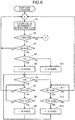
controller 8 is described by using flow diagrams illustrated inFigs. 6 to 9 . - In
Fig. 6 , at S1, thecontroller 8 sets a target frequency ft for generating an air discharge at a set pressure Pt to a value within a range of the lower limit frequency f1 in the load operation to the maximum rotational speed f2 in the load operation, both inclusive, and performs the load operation via theinverter 2. In this operation, the air release means 5 is "closed." - At S2, the
controller 8 determines whether the frequency f is equal to the lower limit frequency f1 in the load operation and the load-side pressure P is equal to or higher than the upper limit pressure P2. In short, this is a determination on whether or not to shift to the no-load operation. If f = f1 and P ≥ P2 are determined (YES), thecontroller 8 shifts to the no-load operation (to be described later), or if not (NO), advances to S3. - At S3, the
controller 8 determines whether the target frequency ft is between the lower bound ff1 and the upper bound ff2 of the rotation-prohibited frequency range. If ff1 < ft < ff2 does not hold (NO), thecontroller 8 returns to S1 and continues the load operation. If ff1 < ft < ff2 holds (YES), thecontroller 8 advances to S4. - At S4, the
controller 8 determines whether the frequency f is higher than the target frequency ft, and advances to S5 if f > ft holds (YES), or advances to S10 if f > ft does not hold (NO). - At S5, the
controller 8 fixedly sets the frequency f to the lower bound ff1 of the rotation-prohibited frequency range. Meanwhile, at S10, thecontroller 8 fixedly sets the output frequency f to the upper bound ff2 of the rotation-prohibited frequency range. After S5 or S10, thecontroller 8 advances to S6. - At S6, the
controller 8 advances to S7 if the frequency f is ff1 (YES), or advances to S11 if the frequency f is not ff1 (NO). - At S7, the
controller 8 determines whether the target frequency ft is between ff1 and ff2 of the rotation-prohibited range frequency range, and advances to S8 if ff1 < ft < ff2 holds (YES) or returns to S1 if ff1 < ft < ff2 does not hold. - At S8, the
controller 8 determines whether the load-side pressure P falls below Pt-ΔPta that is the lower limit threshold pressure for frequency switching. If the load-side pressure P falls below Pt-ΔPta (YES), thecontroller 8 advances to S9, switches the output frequency f to ff2, and fixes the setting. Thereafter, thecontroller 8 returns to S6. On the other hand, if the load-side pressure P does not fall below Pt-ΔPta (NO), thecontroller 8 returns to S7. - Here, the explanation for S6 is again provided. When the
controller 8 determines that the output frequency f is not ff1 (NO) as a result of the determination at S6, thecontroller 8 advances to S11 to determine whether the target frequency ft is between ff1 and ff2 of the rotation-prohibited range frequency range, and advances to S12 if ff1 < ft < ff2 holds (YES). Meanwhile, if ff1 < ft < ff2 holds (NO), thecontroller 8 returns to S1. - When the
controller 8 determines at S12 that the load-side pressure P is higher than Pt+ΔPtb that is the upper limit threshold pressure for frequency switching, thecontroller 8 advances to S13 to switch the output frequency f to ff1 and fix the setting. Thereafter, thecontroller 8 again returns to S6. On the other hand, if the load-side pressure P does not exceed Pt+ΔPtb (NO), thecontroller 8 returns to S12. - As described above, the
controller 8 determines whether or not frequency switching control for keeping the set pressure Pt in the load operation is to be done through the rotation-prohibited frequency range, and when the control is to be done through the rotation-prohibited frequency, switches the frequency by using as a trigger the lower pressure Pt-ΔPta or higher pressure Pt+ΔPtb than the set pressure Pt. Thus, the frequency within the rotation-prohibited frequency range is generated less often and thereby the resonance can be reduced. - Next, using
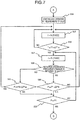
Fig. 7 , a processing flow in the case where to shift to the no-load operation is determined at S2 inFig. 6 . - The
controller 8 "opens" the air release means 5 at S14, and fixedly sets the output frequency to the minimum rotational frequency f0 at S15. - At S16, the
controller 8 determines whether the load-side pressure P is equal to or lower than the target keep pressure P1+ΔP1a in the no-load operation, and keeps the frequency at f0 if P≤P1+ΔP1a holds (NO -> S15). On the other hand, if P≤P1+ΔP1a holds (YES), thecontroller 8 advances to S17 and fixedly sets the frequency f to f1. - At S18, the
controller 8 determines whether the rotation-prohibited frequency range is included between the minimum rotations f0 and the lower limit frequency f1 in the load operation in reference to thememory 8a. If the rotation-prohibited frequency range is included (YES), thecontroller 8 advances to S19, and determines whether or not the load-side pressure P is equal to or lower than P1+ΔP1b that is a pressure higher than the target keep pressure P1+ΔP1a. Thecontroller 8 advances to S20 if the load-side pressure P is equal to or lower than P1+ΔP1b, or returns to S15 and fixedly sets the frequency f to the minimum rotations f0 if the load-side pressure P is higher than P1+ΔP1b (NO). This is because use of a pressure higher than the target keep pressure as the threshold pressure for frequency switching can lead to a reduction in the number of occasions on which the frequency passes through the rotation-prohibited frequency range. - In addition, when determining in S18 that the rotation-prohibited frequency range is not included, the
controller 8 advances to S21 and determines whether the load-side pressure P exceeds the target keep pressure P1+ΔP1a. Thecontroller 8 advances to S20 if the load-side pressure P does not exceed (NO), or returns to S15 and switches the frequency to the minimum rotational frequency f0 if the load-side pressure P exceeds (YES). - At S20, the
controller 8 determines whether or not the load-side pressure P is equal to or lower than the lower limit pressure P1, and returns to the load operation if the load-side pressure P is equal to or lower than the lower limit pressure P1 (YES) or returns to S17 and keeps the output frequency f fixed to f1 if the load-side pressure P is higher than the lower limit pressure P1 (NO). - The above description is provided for the processing flow in the no-load operation.
- As described above, according to the present embodiment, when the rotation-prohibited frequency range is included in a frequency band across which the frequency is switched in the inverter control for keeping the load-side pressure P at a predetermined pressure such as the target pressure Pt, the frequency is switched based on a load-side pressure value which is higher or lower than the predetermined pressure by a certain pressure margin. This reduces the number of frequency switches and decreases the number of occasions on which the frequency passes through the rotation-prohibited frequency range. Accordingly, the occurrence frequency of resonance is also reduced and the reliability of the
air compressor 1 can be enhanced. - Moreover, according to the present embodiment, the relationship between the rotation-prohibited frequency range and the frequency band necessary for control to keep the predetermined pressure is set dynamically. Thus, the resonance reducing effect can be obtained no matter what value is set as a predetermined pressure, such as the target pressure Pt, which can be set to any value as needed.
- Similarly, according to the present embodiment, the rotation-prohibited frequency range can be set to any range as needed through the input-
output device 12. Thus, the resonance reducing effect can be also obtained even if the resonance frequency band is changed or newly generated afterwards, for example, due to aging deterioration of theair compressor 1 or addition or deletion of another auxiliary instrument. - Further, according to the present embodiment, in the frequency control to keep the predetermined pressure such as the target pressure Pt, the predetermined pressure is set as the trigger for frequency switching when the rotation-prohibited frequency range is not included in a band across which the frequency control is performed. This ensures the ability to keep the predetermined pressure.
- Hereinabove, the embodiment of the present invention has been described. The present invention, however, is not limited to the above various components and kinds of processing, but they may be changed in combination or modified in various ways without departing from the spirit of the present invention.
-
- 1 air compressor
- 2 inverter
- 3 motor
- 4 compressor main body
- 5 air release means
- 6 check valve
- 7 pressure detection means
- 8 controller
- 8a memory
- 9, 10 discharge pipe
- 11 power supply
- P load-side pressure
- Pt set pressure
- P1 lower limit pressure (in load operation)
- P2 upper limit pressure (in load operation)
- ΔPta lower pressure margin for Pt
- ΔPtb upper pressure margin for Pt
- ΔP1a upper pressure margin for P1
- ΔP1b upper pressure margin for P1
- f (output) frequency
- ft target frequency
- f0 frequency (minimum rotational frequency) in no-load operation
- f1 lower limit frequency in load operation
- f2 upper limit frequency in load operation
- ff1 lower frequency bound (for keeping pressure Pt in load operation or of a rotation-prohibited frequency range)
- ff2 upper frequency bound (for keeping pressure Pt in load operation or of a rotation-prohibited frequency range)
Claims (12)
- A gas compressor comprising:a compressor main body that compresses gas;a motor that drives and rotates the compressor main body;an inverter that changes a rotational speed of the motor;a check valve that is arranged downstream of the compressor main body;pressure detection means that detects a load-side pressure downstream of the check valve; anda controller that controls an output frequency from the inverter according to the pressure detected by the pressure detection means, whereinthe controller performs control to generate and keep compressed gas with a predetermined pressure by control of increasing and decreasing the frequency, andin a case where a specific frequency is included in a frequency at which to generate the compressed gas with the predetermined pressure, the controller increases or decreases the output frequency from the inverter when the pressure detected by the pressure detection means reaches a pressure which is higher or lower than the predetermined pressure by a certain pressure margin and which corresponds to a frequency not including the specific frequency.
- The gas compressor according to claim 1, wherein
the controller decreases the output frequency to a frequency not including the specific frequency when the detected pressure is higher than the predetermined pressure, and increases the output frequency to a frequency not including the specific frequency when the detected pressure is lower than the predetermined pressure. - The gas compressor according to claim 1, wherein
the frequency not including the specific frequency has a predetermined range to the frequency the frequency at which to generate the compressed gas with the predetermined pressure. - The gas compressor according to claim 1, comprising input means that inputs, to the controller, the predetermined pressure, the specific frequency, the frequency not including the specific frequency, and a pressure not including the specific frequency.
- The gas compressor according to claim 1, comprising display means that displays the predetermined pressure, the specific frequency, the frequency not including the specific frequency, and a pressure not including the specific frequency.
- The gas compressor according to claim 1, wherein the specific frequency is a resonant frequency.
- A gas compressor, comprising:a compressor main body that compresses gas;a motor that drives and rotates the compressor main body;an inverter that changes a rotational speed of the motor;a check valve that is arranged downstream of the compressor main body;air release means that releases the compressed gas upstream of the check valve;pressure detection means that detects a load-side pressure downstream of the check valve; anda controller that controls an output frequency from the inverter according to the pressure detected by the pressure detection means, whereinthe controller controls a no-load operation to generate and keep compressed gas with a predetermined pressure by releasing the compressed gas from the air release means and decreasing the frequency, andin a case where a specific frequency is included in a frequency at which to generate the compressed gas with the predetermined pressure, the controller increases the output frequency to a frequency where the detected pressure has a pressure width than a certain pressure margin and which does not include the specific frequency when the pressure detected by the pressure detection means is lower than the predetermined pressure, and thereafter keeps the frequency until a pressure lower than the predetermined pressure is detected.
- The gas compressor according to claim 7, wherein the pressure lower than the predetermined pressure is a lower limit pressure at which to switch the no-load operation to a load operation.
- The gas compressor according to claim 8, wherein the load operation is an operation with the air release means closed.
- The gas compressor according to claim 7, comprising input means that inputs, to the controller, the predetermined pressure, the specific frequency, the frequency not including the specific frequency, and a pressure not including the specific frequency.
- The gas compressor according to claim 7, comprising display means that displays the predetermined pressure, the specific frequency, the frequency not including the specific frequency, and a pressure not including the specific frequency .
- The gas compressor according to claim 7, wherein the specific frequency is a resonant frequency.
Applications Claiming Priority (1)
| Application Number | Priority Date | Filing Date | Title |
|---|---|---|---|
| PCT/JP2015/081914 WO2017081803A1 (en) | 2015-11-13 | 2015-11-13 | Gas compressor |
Publications (3)
| Publication Number | Publication Date |
|---|---|
| EP3376029A1 true EP3376029A1 (en) | 2018-09-19 |
| EP3376029A4 EP3376029A4 (en) | 2019-11-13 |
| EP3376029B1 EP3376029B1 (en) | 2021-01-06 |
Family
ID=58694808
Family Applications (1)
| Application Number | Title | Priority Date | Filing Date |
|---|---|---|---|
| EP15908323.7A Active EP3376029B1 (en) | 2015-11-13 | 2015-11-13 | Gas compressor |
Country Status (6)
| Country | Link |
|---|---|
| US (2) | US20180291901A1 (en) |
| EP (1) | EP3376029B1 (en) |
| JP (1) | JP6453484B2 (en) |
| CN (1) | CN108138757B (en) |
| TW (1) | TWI640688B (en) |
| WO (1) | WO2017081803A1 (en) |
Families Citing this family (4)
| Publication number | Priority date | Publication date | Assignee | Title |
|---|---|---|---|---|
| KR102336394B1 (en) * | 2017-03-17 | 2021-12-08 | 현대자동차주식회사 | Air supply control method and system for fuelcell |
| CN108501216A (en) * | 2018-03-01 | 2018-09-07 | 镇江北新建材有限公司 | Plasterboard foaming mixing equipment and method for mixing |
| TWI704285B (en) * | 2019-07-25 | 2020-09-11 | 陸澍華 | Method for controlling motor-driven pump in a fluid system |
| CN111472968A (en) * | 2020-05-20 | 2020-07-31 | 领跃电子科技(珠海)有限公司 | Frequency conversion transformation method for air compression station |
Family Cites Families (20)
| Publication number | Priority date | Publication date | Assignee | Title |
|---|---|---|---|---|
| US4227862A (en) * | 1978-09-19 | 1980-10-14 | Frick Company | Solid state compressor control system |
| JPS55164792A (en) | 1979-06-11 | 1980-12-22 | Mayekawa Mfg Co Ltd | Driving mechanism for screw compressor |
| JPH0492715A (en) * | 1990-08-09 | 1992-03-25 | Nippondenso Co Ltd | Control device for automotive air-conditioner |
| JP2675730B2 (en) * | 1992-12-25 | 1997-11-12 | 株式会社日立製作所 | Variable capacity compressor |
| TW389820B (en) * | 1996-11-02 | 2000-05-11 | Sanyo Electric Co | Air conditioner and its operation control method |
| JP3688458B2 (en) * | 1998-03-10 | 2005-08-31 | 株式会社東芝 | Compressor control device |
| AT406693B (en) | 1998-06-16 | 2000-07-25 | Bartelmuss Klaus Ing | DEVICE FOR ADJUSTING THE POSITION OF ONE OF THE BEARINGS OF A ROLLER IN A ROLLER GROUP |
| TW415981B (en) | 1998-07-16 | 2000-12-21 | Samsung Electronics Co Ltd | Washing machine having a hybrid sensor and a control method thereof |
| JP3668616B2 (en) * | 1998-09-17 | 2005-07-06 | 株式会社日立産機システム | Oil-free screw compressor |
| JP2000314564A (en) * | 1999-04-28 | 2000-11-14 | Oyo Keisoku Kenkyusho:Kk | Method of operating freezer and compressor thereof |
| JP3916426B2 (en) * | 2001-08-02 | 2007-05-16 | 株式会社神戸製鋼所 | Screw refrigerator |
| JP4443109B2 (en) * | 2002-12-24 | 2010-03-31 | 株式会社日立産機システム | Compressed air production facility |
| US7921816B2 (en) * | 2005-08-29 | 2011-04-12 | Komatsu Ltd. | Control device for hydraulically driven fan |
| US7895003B2 (en) * | 2007-10-05 | 2011-02-22 | Emerson Climate Technologies, Inc. | Vibration protection in a variable speed compressor |
| JP5521268B2 (en) * | 2007-12-12 | 2014-06-11 | マックス株式会社 | Air compressor and motor control device |
| JP4523981B2 (en) * | 2008-05-21 | 2010-08-11 | 本田技研工業株式会社 | Fuel cell system |
| JP5183382B2 (en) * | 2008-09-18 | 2013-04-17 | 芝浦メカトロニクス株式会社 | Substrate processing apparatus and substrate processing method |
| CN101672271B (en) * | 2009-10-19 | 2012-05-23 | 北京乐普四方方圆科技股份有限公司(中国) | Air compressor energy-saving controller with constant pressure and dormancy and control method |
| CN102650279A (en) * | 2011-02-23 | 2012-08-29 | 上海慎邦电子科技有限公司 | Control method for variable frequency and constant pressure air supply of air compressor |
| CN204344430U (en) * | 2014-12-24 | 2015-05-20 | 深圳市大众新源节能科技有限公司 | A kind of frequency-converting control device of compressor |
-
2015
- 2015-11-13 JP JP2017549947A patent/JP6453484B2/en active Active
- 2015-11-13 WO PCT/JP2015/081914 patent/WO2017081803A1/en active Application Filing
- 2015-11-13 EP EP15908323.7A patent/EP3376029B1/en active Active
- 2015-11-13 CN CN201580083249.6A patent/CN108138757B/en active Active
- 2015-11-13 US US15/761,987 patent/US20180291901A1/en not_active Abandoned
-
2016
- 2016-11-11 TW TW105136832A patent/TWI640688B/en active
-
2021
- 2021-02-05 US US17/168,651 patent/US11773855B2/en active Active
Also Published As
| Publication number | Publication date |
|---|---|
| US20180291901A1 (en) | 2018-10-11 |
| TWI640688B (en) | 2018-11-11 |
| JP6453484B2 (en) | 2019-01-16 |
| CN108138757B (en) | 2019-10-18 |
| EP3376029A4 (en) | 2019-11-13 |
| JPWO2017081803A1 (en) | 2018-05-24 |
| US11773855B2 (en) | 2023-10-03 |
| WO2017081803A1 (en) | 2017-05-18 |
| TW201719021A (en) | 2017-06-01 |
| CN108138757A (en) | 2018-06-08 |
| EP3376029B1 (en) | 2021-01-06 |
| US20210156383A1 (en) | 2021-05-27 |
Similar Documents
| Publication | Publication Date | Title |
|---|---|---|
| US11773855B2 (en) | Gas compressor | |
| EP1851438B1 (en) | System and method for controlling a variable speed compressor during stopping | |
| US20170268498A1 (en) | Multistage Compressor | |
| US9157432B2 (en) | Compression apparatus | |
| JPWO2018179789A1 (en) | Gas compressor | |
| WO2013014808A1 (en) | System for controlling number of compressors | |
| JP5415484B2 (en) | Steam system | |
| KR100597864B1 (en) | Method of controlling a plurality of compressors | |
| JP4795977B2 (en) | Compressor operation method | |
| WO2020213353A1 (en) | Gas compressor | |
| KR101837700B1 (en) | Invertor controller for compressure | |
| JP6940686B2 (en) | Gas compressor | |
| JP5105854B2 (en) | Operation control method for inverter-driven compressor and inverter-driven compressor | |
| JP6812248B2 (en) | Capacity control method for multi-stage oil-free screw compressor and multi-stage oil-free screw compressor | |
| JP2009024929A (en) | Compressor control device, refrigerating air conditioning device and rotary compressor | |
| KR20070053939A (en) | Refrigerator and control method of the same | |
| JP2006312900A (en) | Compressed gas supply device | |
| JP2006234320A (en) | Refrigerating machine and its capacity control method | |
| JP2005083214A (en) | Compressor unit | |
| JP2003279185A (en) | Cryogenic refrigerator | |
| EP3859156A1 (en) | Gas compressor and control method therefor | |
| JP2005042562A (en) | Control device and gas supply device | |
| JP2001140768A (en) | Manufacturing facility for compressed air | |
| JP2022157242A (en) | Compressor and system for controlling compressor | |
| JP2009121252A (en) | Compressor |
Legal Events
| Date | Code | Title | Description |
|---|---|---|---|
| STAA | Information on the status of an ep patent application or granted ep patent |
Free format text: STATUS: THE INTERNATIONAL PUBLICATION HAS BEEN MADE |
|
| PUAI | Public reference made under article 153(3) epc to a published international application that has entered the european phase |
Free format text: ORIGINAL CODE: 0009012 |
|
| STAA | Information on the status of an ep patent application or granted ep patent |
Free format text: STATUS: REQUEST FOR EXAMINATION WAS MADE |
|
| 17P | Request for examination filed |
Effective date: 20180323 |
|
| AK | Designated contracting states |
Kind code of ref document: A1 Designated state(s): AL AT BE BG CH CY CZ DE DK EE ES FI FR GB GR HR HU IE IS IT LI LT LU LV MC MK MT NL NO PL PT RO RS SE SI SK SM TR |
|
| AX | Request for extension of the european patent |
Extension state: BA ME |
|
| DAV | Request for validation of the european patent (deleted) | ||
| DAX | Request for extension of the european patent (deleted) | ||
| A4 | Supplementary search report drawn up and despatched |
Effective date: 20191016 |
|
| RIC1 | Information provided on ipc code assigned before grant |
Ipc: F04B 49/08 20060101ALI20191010BHEP Ipc: F04B 27/08 20060101AFI20191010BHEP Ipc: F04B 35/04 20060101ALI20191010BHEP Ipc: F04B 49/06 20060101ALI20191010BHEP Ipc: F04B 49/20 20060101ALI20191010BHEP Ipc: F04B 39/00 20060101ALI20191010BHEP |
|
| GRAP | Despatch of communication of intention to grant a patent |
Free format text: ORIGINAL CODE: EPIDOSNIGR1 |
|
| STAA | Information on the status of an ep patent application or granted ep patent |
Free format text: STATUS: GRANT OF PATENT IS INTENDED |
|
| INTG | Intention to grant announced |
Effective date: 20200624 |
|
| GRAS | Grant fee paid |
Free format text: ORIGINAL CODE: EPIDOSNIGR3 |
|
| GRAA | (expected) grant |
Free format text: ORIGINAL CODE: 0009210 |
|
| STAA | Information on the status of an ep patent application or granted ep patent |
Free format text: STATUS: THE PATENT HAS BEEN GRANTED |
|
| AK | Designated contracting states |
Kind code of ref document: B1 Designated state(s): AL AT BE BG CH CY CZ DE DK EE ES FI FR GB GR HR HU IE IS IT LI LT LU LV MC MK MT NL NO PL PT RO RS SE SI SK SM TR |
|
| REG | Reference to a national code |
Ref country code: GB Ref legal event code: FG4D |
|
| REG | Reference to a national code |
Ref country code: AT Ref legal event code: REF Ref document number: 1352652 Country of ref document: AT Kind code of ref document: T Effective date: 20210115 Ref country code: CH Ref legal event code: EP |
|
| REG | Reference to a national code |
Ref country code: DE Ref legal event code: R096 Ref document number: 602015064643 Country of ref document: DE |
|
| REG | Reference to a national code |
Ref country code: IE Ref legal event code: FG4D |
|
| REG | Reference to a national code |
Ref country code: NL Ref legal event code: MP Effective date: 20210106 |
|
| REG | Reference to a national code |
Ref country code: AT Ref legal event code: MK05 Ref document number: 1352652 Country of ref document: AT Kind code of ref document: T Effective date: 20210106 |
|
| REG | Reference to a national code |
Ref country code: LT Ref legal event code: MG9D |
|
| PG25 | Lapsed in a contracting state [announced via postgrant information from national office to epo] |
Ref country code: PT Free format text: LAPSE BECAUSE OF FAILURE TO SUBMIT A TRANSLATION OF THE DESCRIPTION OR TO PAY THE FEE WITHIN THE PRESCRIBED TIME-LIMIT Effective date: 20210506 Ref country code: NO Free format text: LAPSE BECAUSE OF FAILURE TO SUBMIT A TRANSLATION OF THE DESCRIPTION OR TO PAY THE FEE WITHIN THE PRESCRIBED TIME-LIMIT Effective date: 20210406 Ref country code: BG Free format text: LAPSE BECAUSE OF FAILURE TO SUBMIT A TRANSLATION OF THE DESCRIPTION OR TO PAY THE FEE WITHIN THE PRESCRIBED TIME-LIMIT Effective date: 20210406 Ref country code: FI Free format text: LAPSE BECAUSE OF FAILURE TO SUBMIT A TRANSLATION OF THE DESCRIPTION OR TO PAY THE FEE WITHIN THE PRESCRIBED TIME-LIMIT Effective date: 20210106 Ref country code: GR Free format text: LAPSE BECAUSE OF FAILURE TO SUBMIT A TRANSLATION OF THE DESCRIPTION OR TO PAY THE FEE WITHIN THE PRESCRIBED TIME-LIMIT Effective date: 20210407 Ref country code: HR Free format text: LAPSE BECAUSE OF FAILURE TO SUBMIT A TRANSLATION OF THE DESCRIPTION OR TO PAY THE FEE WITHIN THE PRESCRIBED TIME-LIMIT Effective date: 20210106 Ref country code: LT Free format text: LAPSE BECAUSE OF FAILURE TO SUBMIT A TRANSLATION OF THE DESCRIPTION OR TO PAY THE FEE WITHIN THE PRESCRIBED TIME-LIMIT Effective date: 20210106 |
|
| PG25 | Lapsed in a contracting state [announced via postgrant information from national office to epo] |
Ref country code: SE Free format text: LAPSE BECAUSE OF FAILURE TO SUBMIT A TRANSLATION OF THE DESCRIPTION OR TO PAY THE FEE WITHIN THE PRESCRIBED TIME-LIMIT Effective date: 20210106 Ref country code: LV Free format text: LAPSE BECAUSE OF FAILURE TO SUBMIT A TRANSLATION OF THE DESCRIPTION OR TO PAY THE FEE WITHIN THE PRESCRIBED TIME-LIMIT Effective date: 20210106 Ref country code: RS Free format text: LAPSE BECAUSE OF FAILURE TO SUBMIT A TRANSLATION OF THE DESCRIPTION OR TO PAY THE FEE WITHIN THE PRESCRIBED TIME-LIMIT Effective date: 20210106 Ref country code: PL Free format text: LAPSE BECAUSE OF FAILURE TO SUBMIT A TRANSLATION OF THE DESCRIPTION OR TO PAY THE FEE WITHIN THE PRESCRIBED TIME-LIMIT Effective date: 20210106 Ref country code: AT Free format text: LAPSE BECAUSE OF FAILURE TO SUBMIT A TRANSLATION OF THE DESCRIPTION OR TO PAY THE FEE WITHIN THE PRESCRIBED TIME-LIMIT Effective date: 20210106 |
|
| PG25 | Lapsed in a contracting state [announced via postgrant information from national office to epo] |
Ref country code: IS Free format text: LAPSE BECAUSE OF FAILURE TO SUBMIT A TRANSLATION OF THE DESCRIPTION OR TO PAY THE FEE WITHIN THE PRESCRIBED TIME-LIMIT Effective date: 20210506 |
|
| REG | Reference to a national code |
Ref country code: DE Ref legal event code: R097 Ref document number: 602015064643 Country of ref document: DE |
|
| PG25 | Lapsed in a contracting state [announced via postgrant information from national office to epo] |
Ref country code: CZ Free format text: LAPSE BECAUSE OF FAILURE TO SUBMIT A TRANSLATION OF THE DESCRIPTION OR TO PAY THE FEE WITHIN THE PRESCRIBED TIME-LIMIT Effective date: 20210106 Ref country code: EE Free format text: LAPSE BECAUSE OF FAILURE TO SUBMIT A TRANSLATION OF THE DESCRIPTION OR TO PAY THE FEE WITHIN THE PRESCRIBED TIME-LIMIT Effective date: 20210106 Ref country code: SM Free format text: LAPSE BECAUSE OF FAILURE TO SUBMIT A TRANSLATION OF THE DESCRIPTION OR TO PAY THE FEE WITHIN THE PRESCRIBED TIME-LIMIT Effective date: 20210106 |
|
| PLBE | No opposition filed within time limit |
Free format text: ORIGINAL CODE: 0009261 |
|
| STAA | Information on the status of an ep patent application or granted ep patent |
Free format text: STATUS: NO OPPOSITION FILED WITHIN TIME LIMIT |
|
| PG25 | Lapsed in a contracting state [announced via postgrant information from national office to epo] |
Ref country code: DK Free format text: LAPSE BECAUSE OF FAILURE TO SUBMIT A TRANSLATION OF THE DESCRIPTION OR TO PAY THE FEE WITHIN THE PRESCRIBED TIME-LIMIT Effective date: 20210106 Ref country code: SK Free format text: LAPSE BECAUSE OF FAILURE TO SUBMIT A TRANSLATION OF THE DESCRIPTION OR TO PAY THE FEE WITHIN THE PRESCRIBED TIME-LIMIT Effective date: 20210106 Ref country code: RO Free format text: LAPSE BECAUSE OF FAILURE TO SUBMIT A TRANSLATION OF THE DESCRIPTION OR TO PAY THE FEE WITHIN THE PRESCRIBED TIME-LIMIT Effective date: 20210106 |
|
| 26N | No opposition filed |
Effective date: 20211007 |
|
| PG25 | Lapsed in a contracting state [announced via postgrant information from national office to epo] |
Ref country code: AL Free format text: LAPSE BECAUSE OF FAILURE TO SUBMIT A TRANSLATION OF THE DESCRIPTION OR TO PAY THE FEE WITHIN THE PRESCRIBED TIME-LIMIT Effective date: 20210106 Ref country code: ES Free format text: LAPSE BECAUSE OF FAILURE TO SUBMIT A TRANSLATION OF THE DESCRIPTION OR TO PAY THE FEE WITHIN THE PRESCRIBED TIME-LIMIT Effective date: 20210106 |
|
| PG25 | Lapsed in a contracting state [announced via postgrant information from national office to epo] |
Ref country code: SI Free format text: LAPSE BECAUSE OF FAILURE TO SUBMIT A TRANSLATION OF THE DESCRIPTION OR TO PAY THE FEE WITHIN THE PRESCRIBED TIME-LIMIT Effective date: 20210106 |
|
| PG25 | Lapsed in a contracting state [announced via postgrant information from national office to epo] |
Ref country code: IT Free format text: LAPSE BECAUSE OF FAILURE TO SUBMIT A TRANSLATION OF THE DESCRIPTION OR TO PAY THE FEE WITHIN THE PRESCRIBED TIME-LIMIT Effective date: 20210106 |
|
| PG25 | Lapsed in a contracting state [announced via postgrant information from national office to epo] |
Ref country code: IS Free format text: LAPSE BECAUSE OF FAILURE TO SUBMIT A TRANSLATION OF THE DESCRIPTION OR TO PAY THE FEE WITHIN THE PRESCRIBED TIME-LIMIT Effective date: 20210506 |
|
| PG25 | Lapsed in a contracting state [announced via postgrant information from national office to epo] |
Ref country code: MC Free format text: LAPSE BECAUSE OF FAILURE TO SUBMIT A TRANSLATION OF THE DESCRIPTION OR TO PAY THE FEE WITHIN THE PRESCRIBED TIME-LIMIT Effective date: 20210106 |
|
| REG | Reference to a national code |
Ref country code: CH Ref legal event code: PL |
|
| PG25 | Lapsed in a contracting state [announced via postgrant information from national office to epo] |
Ref country code: LU Free format text: LAPSE BECAUSE OF NON-PAYMENT OF DUE FEES Effective date: 20211113 Ref country code: BE Free format text: LAPSE BECAUSE OF NON-PAYMENT OF DUE FEES Effective date: 20211130 |
|
| REG | Reference to a national code |
Ref country code: BE Ref legal event code: MM Effective date: 20211130 |
|
| PG25 | Lapsed in a contracting state [announced via postgrant information from national office to epo] |
Ref country code: LI Free format text: LAPSE BECAUSE OF NON-PAYMENT OF DUE FEES Effective date: 20211130 Ref country code: CH Free format text: LAPSE BECAUSE OF NON-PAYMENT OF DUE FEES Effective date: 20211130 |
|
| PG25 | Lapsed in a contracting state [announced via postgrant information from national office to epo] |
Ref country code: IE Free format text: LAPSE BECAUSE OF NON-PAYMENT OF DUE FEES Effective date: 20211113 |
|
| PG25 | Lapsed in a contracting state [announced via postgrant information from national office to epo] |
Ref country code: HU Free format text: LAPSE BECAUSE OF FAILURE TO SUBMIT A TRANSLATION OF THE DESCRIPTION OR TO PAY THE FEE WITHIN THE PRESCRIBED TIME-LIMIT; INVALID AB INITIO Effective date: 20151113 |
|
| PG25 | Lapsed in a contracting state [announced via postgrant information from national office to epo] |
Ref country code: NL Free format text: LAPSE BECAUSE OF NON-PAYMENT OF DUE FEES Effective date: 20210206 Ref country code: CY Free format text: LAPSE BECAUSE OF FAILURE TO SUBMIT A TRANSLATION OF THE DESCRIPTION OR TO PAY THE FEE WITHIN THE PRESCRIBED TIME-LIMIT Effective date: 20210106 |
|
| PGFP | Annual fee paid to national office [announced via postgrant information from national office to epo] |
Ref country code: GB Payment date: 20230928 Year of fee payment: 9 |
|
| PGFP | Annual fee paid to national office [announced via postgrant information from national office to epo] |
Ref country code: FR Payment date: 20230929 Year of fee payment: 9 |
|
| PGFP | Annual fee paid to national office [announced via postgrant information from national office to epo] |
Ref country code: DE Payment date: 20230929 Year of fee payment: 9 |
|
| PG25 | Lapsed in a contracting state [announced via postgrant information from national office to epo] |
Ref country code: MK Free format text: LAPSE BECAUSE OF FAILURE TO SUBMIT A TRANSLATION OF THE DESCRIPTION OR TO PAY THE FEE WITHIN THE PRESCRIBED TIME-LIMIT Effective date: 20210106 |