EP3375937B1 - Véhicule de balayage de route - Google Patents
Véhicule de balayage de route Download PDFInfo
- Publication number
- EP3375937B1 EP3375937B1 EP18155486.6A EP18155486A EP3375937B1 EP 3375937 B1 EP3375937 B1 EP 3375937B1 EP 18155486 A EP18155486 A EP 18155486A EP 3375937 B1 EP3375937 B1 EP 3375937B1
- Authority
- EP
- European Patent Office
- Prior art keywords
- liquid
- air
- air flow
- flow path
- water
- Prior art date
- Legal status (The legal status is an assumption and is not a legal conclusion. Google has not performed a legal analysis and makes no representation as to the accuracy of the status listed.)
- Active
Links
- 238000010408 sweeping Methods 0.000 title claims description 27
- 239000007788 liquid Substances 0.000 claims description 101
- 239000000428 dust Substances 0.000 claims description 93
- XLYOFNOQVPJJNP-UHFFFAOYSA-N water Substances O XLYOFNOQVPJJNP-UHFFFAOYSA-N 0.000 claims description 93
- 238000001914 filtration Methods 0.000 claims description 53
- 230000007246 mechanism Effects 0.000 claims description 32
- 239000007921 spray Substances 0.000 claims description 8
- 239000012530 fluid Substances 0.000 claims description 5
- 238000004140 cleaning Methods 0.000 description 27
- 230000001629 suppression Effects 0.000 description 12
- 239000000203 mixture Substances 0.000 description 8
- 239000002245 particle Substances 0.000 description 7
- 241001417527 Pempheridae Species 0.000 description 4
- 239000000463 material Substances 0.000 description 4
- 238000009736 wetting Methods 0.000 description 3
- 244000007853 Sarothamnus scoparius Species 0.000 description 2
- 230000000694 effects Effects 0.000 description 2
- 230000000717 retained effect Effects 0.000 description 2
- 241000130993 Scarabaeus <genus> Species 0.000 description 1
- 239000010419 fine particle Substances 0.000 description 1
- 238000000926 separation method Methods 0.000 description 1
- 238000005507 spraying Methods 0.000 description 1
- 238000005406 washing Methods 0.000 description 1
Images

Classifications
-
- E—FIXED CONSTRUCTIONS
- E01—CONSTRUCTION OF ROADS, RAILWAYS, OR BRIDGES
- E01H—STREET CLEANING; CLEANING OF PERMANENT WAYS; CLEANING BEACHES; DISPERSING OR PREVENTING FOG IN GENERAL CLEANING STREET OR RAILWAY FURNITURE OR TUNNEL WALLS
- E01H1/00—Removing undesirable matter from roads or like surfaces, with or without moistening of the surface
- E01H1/08—Pneumatically dislodging or taking-up undesirable matter or small objects; Drying by heat only or by streams of gas; Cleaning by projecting abrasive particles
- E01H1/0827—Dislodging by suction; Mechanical dislodging-cleaning apparatus with independent or dependent exhaust, e.g. dislodging-sweeping machines with independent suction nozzles ; Mechanical loosening devices working under vacuum
- E01H1/0836—Apparatus dislodging all of the dirt by suction ; Suction nozzles
- E01H1/0845—Apparatus dislodging all of the dirt by suction ; Suction nozzles with mechanical loosening or feeding instruments for the dirt to be sucked- up, e.g. brushes, scrapers
-
- E—FIXED CONSTRUCTIONS
- E01—CONSTRUCTION OF ROADS, RAILWAYS, OR BRIDGES
- E01H—STREET CLEANING; CLEANING OF PERMANENT WAYS; CLEANING BEACHES; DISPERSING OR PREVENTING FOG IN GENERAL CLEANING STREET OR RAILWAY FURNITURE OR TUNNEL WALLS
- E01H1/00—Removing undesirable matter from roads or like surfaces, with or without moistening of the surface
- E01H1/08—Pneumatically dislodging or taking-up undesirable matter or small objects; Drying by heat only or by streams of gas; Cleaning by projecting abrasive particles
Definitions
- the invention relates to a road-sweeping vehicle.
- suction-type cleaning vehicles for the purpose of cleaning and removing dirt, litter or other debris from an area.
- road sweeping vehicles are commonly used to clean roads or other paved surfaces.
- Such vehicles comprise a motorised debris collection mechanism mounted on a vehicle chassis, which is supported on a set of drivable wheels.
- the debris collection mechanism typically includes both a mechanical sweeping device, such as rotating brushes or the like, and a suction device, which may act to draw material into a collection chamber housed on the vehicle.
- Sweepers of this type are manufactured, for example, by Johnston Sweepers Limited and Scarab Sweepers Limited, and are well known to a person skilled in the art.
- Suction-type cleaning vehicles often also include dust suppression systems for reducing the amount of dust emitted when collecting debris.
- the dust suppression system includes a water tank housed on the vehicle and one or more water sprayers for wetting the paved surface before the debris are collected. This reduces the amount of flying dust particles caused by the brushes and forms a mixture of dirt and water on the paved surface. The mixture is then drawn into the collection chamber, where it falls to the bottom of the collection chamber so that fewer dust particles are emitted with the exhaust air.
- the present invention arises from the realisation that fine dust particles can be blown out from a cleaning vehicle's debris collection mechanism even when a dust suppression system is used.
- dust suppression systems also present the drawback that they only work for a limited amount of time, as they cease to be effective when the water tank is empty.
- GB 25,003 discloses a road dust collector in which collected air is directed along a tortuous path above a compartment that contains fluid. The air is forces to impinge on the fluid, which retains fine particles in the air.
- DE 2221201 discloses a road sweeper in which a dirt receiving container is partially filled with water, and where the incoming air is guided to below the water surface.
- the liquid-based dust filtration system does not require the road surface to be wetted in order to function. This enables a road surface to be cleaned without wetting it, whilst still reducing the amount of dust emitted.
- the liquid-based dust filtration system is self-contained, meaning that its liquid (which is preferably water) is not shared with any other systems on the suction-type cleaning vehicle.
- the suction-type cleaning vehicle also has a conventional dust suppression system, which has its own dedicated water tank (i.e. the water tank is separate from the liquid-based dust filtration system) and sprayers arranged to wet a surface under the suction-type cleaning vehicle.
- the suction-type cleaning vehicle of the present invention can suppress dust emission for longer periods of time than conventional suction-type cleaning vehicles, as the water-based dust filtration system remains effective even when the water tank for the conventional dust suppression system has run dry.
- a road sweeping vehicle as set out in claim 1.
- the road sweeping vehicle comprises: a debris suction mechanism supported on a chassis for generating an air flow path between an inlet suction port and an exhaust port, whereby debris located around the inlet suction port are entrained in the air flow; a collection chamber for receiving the entrained debris, wherein the collecting chamber is located on the air flow path after the inlet suction port; and a liquid-based dust filtration system located on the air flow path after the collection chamber, wherein the liquid-based dust filtration system is arranged to remove dust from air that has flowed through the collection chamber.
- the air flow path may be defined by a passageway, e.g. formed from flexible hosing or the like.
- the air flow path may be directed into the collection chamber in a manner to permit the entrained debris to drop from the flow of air. This may be achieved in a conventional manner by widening the passageway for the air flow, which reduces its velocity.
- a filtering or other separation device may be used.
- the inlet suction port may comprise a suction nozzle or intake aperture.
- the inlet suction port may be located immediately rearwardly of a mechanical sweeping device, e.g. a cylindrical brush extending across the underside of the vehicle.
- One or more circular brushes (known as kerb or gutter brooms) may also be mounted between the front and rear wheels.
- the inlet suction port may be located on a hose extending from the top or the side of the vehicle.
- the air flow path exits the collection chamber via an outlet of the collection chamber and subsequently passes through the liquid-based dust filtration system.
- the liquid-based dust filtration system may use water as a liquid filter, although use of other liquid may be possible.
- the liquid-based dust filtration system may be referred to as a water-based dust filtration system herein.
- the liquid-based dust filtration system may use any liquid-based filter capable of capturing dust and debris from the air flow such that the captured dust and debris remain in liquid contained in the filter.
- the air flow path exits the debris suction mechanism via the exhaust port.
- the volume of liquid in the liquid-based dust filtration system may remain substantially constant over time (as the liquid is not sprayed out or used for another dust suppression system).
- the liquid-based dust filtration system may include one or more ports for adding and removing liquid and for cleaning.
- the debris suction mechanism includes a rotatable fan for causing air to flow along the air flow path.
- the liquid-based dust filtration system is located on the air flow path downstream of the rotatable fan, e.g. between the fan and the exhaust port.
- the air inlet of the water-based dust filtration system may be connected to an outlet of the rotatable fan and the air outlet of the water-based dust filtration system may be connected to the exhaust port of the debris suction mechanism.
- the liquid-based dust filtration system includes a dedicated liquid supply, and an air inlet configured to cause air flowing along the air flow path to mix with liquid from the dedicated liquid supply to remove dust from the air flow.
- the dedicated liquid supply comprises a liquid bath for holding a volume of liquid, and the air inlet is arranged to direct air flowing along the air flow path into engagement with the volume of liquid.
- the dedicated liquid supply may be a self-contained water bath.
- “dedicated” or “self-contained” may mean that liquid in the liquid bath is used solely for the purpose of filtering air flowing through the water-based dust filtration system, i.e. it is not shared with any other systems on board the suction-type cleaning vehicle.
- the air inlet may be arranged to direct air into the volume of liquid so that air flowing along the air flow path bubbles through the volume of liquid.
- the air inlet may be a pipe having an opening inside the liquid bath below the liquid level, such that air flowing along the air flow path must pass through liquid in the liquid bath. As the air passes through the liquid it mixes with the liquid, such that dust and other debris carried by the air become wet and are captured in the liquid bath.
- the air inlet may be arranged to direct air on to a top surface of the volume of liquid.
- the air flowing along the air flow path is thus incident on the surface of the liquid in the liquid bath, which can cause liquid to splash up, thereby thoroughly mixing the air and the liquid such that dust and other debris carried by the air becomes wet and falls down into the liquid bath.
- the air inlet may comprise a constriction in a region where air flowing along the air flow path mixes with liquid from the dedicated liquid supply. This arrangement may enable the Venturi effect to be used to enhance the mixing of liquid with the air flow.
- An aperture in the pipe that is in fluid communication with the volume of liquid may be provided near the constriction. The constriction causes a drop in air pressure in the pipe at the constriction, causing liquid to flow into the pipe through the aperture and mix with the air flow.
- the liquid-based dust filtration system comprises an upright column that defines the air flow path for air after it has mixed with liquid from the dedicated liquid supply.
- the column may be arranged to remove liquid droplets from the air flow and return them to the volume of liquid.
- the upright column is positioned above the liquid bath, such that any liquid droplets entrained up the column by the air flow fall back down into the liquid bath under their own weight. This avoids liquid droplets and any dust or debris trapped in the liquid droplets from being expelled from the debris suction mechanism.
- the air flow velocity along the air flow path can be taken into account to ensure that liquid droplets will not reach the top of the column.
- the column may comprise a flow deflector arranged to inhibit liquid from the dedicated liquid supply from escaping from the exhaust port.
- the flow deflector may include one or more baffles and/or a mesh screen.
- the baffles may provide surfaces inside the column with which the entrained liquid droplets may collide, so that they can then drip back down into the liquid bath.
- the baffles may be a series of inclined plates disposed inside the column.
- the mesh screen serves to capture any entrained liquid droplets or debris, so that they may fall back down into the water bath.
- the mesh screen can be arranged such that it covers an internal cross-section of the column, such that air passing through the column must pass through the mesh screen.
- the debris suction mechanism comprises a water tank, and a spray in fluid communication with the water tank, wherein the spray is arranged to deliver water outside the vehicle in the vicinity of the inlet suction port.
- the debris suction mechanism may thus be arranged to wet a road surface under the road sweeping vehicle.
- the water tank is independent of the liquid-based dust filtration system.
- the spray may be selectively operable.
- the spray may thus be separate from the liquid-based dust filtration system, and can be used on its own or in combination with the liquid-based dust filtration system.
- any dust or debris on the road surface will become wet and so will not form a dust cloud when they are swept by a sweeping mechanism on the road sweeping vehicle.
- a water and dirt mixture will thus form on the road surface, which is entrained into the collection chamber by the debris suction mechanism.
- the water-based dust filtration system works independently from the dust suppression system, it can reduce the amount of dust emitted by the debris suction mechanism even when the debris suction mechanism is turned off (i.e. when water is not sprayed from the water tank via the sprayers). This enables the suction-type cleaning vehicle of the invention to be used in situations where it is desirable to keep the road surface dry.
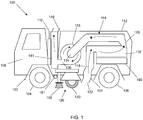
- Fig. 1 shows a side view of a suction-type cleaning vehicle 100 that is an embodiment of the invention.
- the suction-type cleaning vehicle 100 is a road sweeping vehicle designed to remove dirt litter or debris from a road or paved surface.
- the suction-type cleaning vehicle 100 comprises a chassis 102 supported by a pair of front wheels 104 and a pair of rear wheels 106.
- a driver cabin 108 is mounted on the chassis 102 over the front wheels 104.
- the vehicle engine (not shown) is located under the driver cabin 108 and has an engine exhaust 110 mounted on the chassis 102 behind the driver cabin 108.
- Mounted on the chassis behind the engine exhaust 110 and driver cabin 108 is a container 112, which may be an airtight container, which contains a debris suction mechanism 114.
- the container 112 is made transparent in Fig. 1 . In normal use the debris suction mechanism 114 would be not be visible in use.
- the air flow from the inlet suction port 122 travels through the passageway 120 to a collection chamber 132 in the container 112.
- the passageway 120 widens into the collection chamber 132, which may encourage the debris entrained in the air flow to be deposited.
- a filter (not shown) may be mounted in or at the entrance to the collection chamber 132, as is conventionally known.
- the fan housing 116 includes an annular air flow passage which circulates the air flow from a central entrance inlet 134 connected to receive air from the passageway 120 to an outlet 136.
- the suction-type cleaning vehicle 100 also includes a dust suppression system having a water tank 160 and sprayer 161.
- the sprayer 161 is a bar of sprayers disposed behind the front wheels 104.
- the sprayer 161 is connected to the water tank 160 by a pipe (not shown), so that water from the water tank can be sprayed onto a paved surface in front of the sweeping mechanism 126 in order to wet it. In this manner, dust and debris present on the paved surface become wet, and do not create a dust cloud when they are swept by the mechanical sweeping mechanism 126.
- the suction-type cleaning vehicle 100 shown in Fig. 1 includes a liquid-based (e.g. water-based) dust filtration system 141 connected between an outlet 136 of the fan housing 116 and an exhaust port 140 on the roof of the vehicle 100.
- a liquid-based dust filtration system 141 connected between an outlet 136 of the fan housing 116 and an exhaust port 140 on the roof of the vehicle 100.
- air that has flowed through the collection chamber 132 must flow through the water-based dust filtration system 141 before it exits the debris suction mechanism 114 via the exhaust port 140.
- the water-based dust filtration system is self-contained. For example, it has a dedicated water bath (not shown in Fig. 1 ) that is separate from the water tank 160.
- the water-based dust filtration system is designed to capture dust and debris carried by the air flow which were not deposited in the collection chamber 132, so that air expelled from the exhaust port 140 is clean.
- the water-based dust filtration system typically operates by directing exhaust air from the fan through a dedicated liquid filter, which may be in the form of a water bath through which the exhaust air is bubbled or air-based droplets.
- the liquid filter (which is preferably water) attracts and retains particles (e.g. dust particles) carried by the exhaust air.
- the water-based dust filtration system is configured to prevent the liquid filter from escaping through the exhaust port 140 so that the particles are retained.
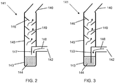
- Figs. 2-4 show examples of different liquid-based (e.g. water-based) dust filtration systems 141 which could be used in a suction-type cleaning vehicle of the invention, such as vehicle 100 shown in Fig. 1 .
- the water-based dust filtration system 141 has an air inlet 142 which is connected to the outlet 136 of the fan housing 116.
- a water bath 143 containing water 144.
- a hollow column 145 Above the water bath 143 there is a hollow column 145 which is connected at its upper end to the exhaust port 140. Inside the column are disposed a series of inclined baffles 146.
- the air inlet 142 includes a side wall 147 for deflecting the air flow from the outlet 136 of the fan housing 116 towards the surface of the water 144, as shown by arrow 148. This causes the water to splash up and mix with the air, so that any dust or debris carried by the airflow become wet and fall down into the water 144.
- the air flow may be particularly strong, such that water droplets (which could contain dust or debris) are entrained up the column 145 towards the exhaust port 140.
- the inclined baffles 146 cause the air flow to zig-zag as it climbs the column, as shown by arrows 149.
- the air inlet 142 includes a pipe 150 which extends below the surface of the water 144 in the water bath 143.
- the pipe 150 includes a section 151 with a reduced diameter so as to form a constriction for the air flow. Other forms of constriction can also be used.
- Section 151 of the pipe 150 includes an aperture on its side wall to the water bath 143. The mixture of air and water in this case is enhanced due to the Venturi effect. As air flows through the constriction in the pipe 150, there is a reduction in air pressure near the aperture causing water to flow into the pipe 150 through the aperture and mix with the air flow, as shown by the arrow 152.
- the end of the pipe 150 may be situated either above or below the water level of the water bath 143. If the end of the pipe is situated above the water level of the water bath 143, water will be sprayed upwards into the column 145 where it is caught by the baffles 146 and side walls of the column 145. Through the mixing of water with the air flow, dust and debris carried by the air flow will become wet and remain captured in the water bath 143.
- the column 145 and baffles 146 shown in Fig. 4 serve the same purpose as those discussed above in relation to Fig. 2 .
- the suction-type cleaning vehicle 100 can operate in either a "dry” mode or a "wet” mode.
- the dust suppression system is not used, i.e. water is not sprayed from the water tank 160 onto the paved surface. The paved surface can therefore remain dry whilst the suction-type cleaning vehicle 100 cleans the paved surface. Dust and debris present on the paved surface are swept by the sweeping mechanism 126 and then entrained along the air flow path as described above. Dust and debris are filtered out of the air flow by the water-based dust filtration system 141, such that air expelled from exhaust port 140 is clean.
- the suction-type cleaning vehicle of the invention In the "wet” mode, the dust suppression system is used in its usual way. The combination of both the dust suppression system and the water-based dust filtration system can greatly reduce the amount of dust produced when cleaning a paved surface compared to conventional suction-type cleaning vehicles.
Landscapes
- Engineering & Computer Science (AREA)
- Architecture (AREA)
- Civil Engineering (AREA)
- Structural Engineering (AREA)
- Separation Of Particles Using Liquids (AREA)
- Cleaning Of Streets, Tracks, Or Beaches (AREA)
Claims (9)
- Véhicule de balayage de route (100) comprenant :un mécanisme d'aspiration de débris (114) supporté sur un châssis (102) pour générer un trajet d'écoulement d'air (118) entre un orifice d'aspiration d'entrée (122) et un orifice d'échappement, dans lequel le mécanisme d'aspiration de débris comprend un ventilateur rotatif pour amener de l'air à circuler le long du trajet d'écoulement d'air, de telle sorte que des débris situés autour de l'orifice d'aspiration d'entrée sont entraînés dans le trajet d'écoulement d'air ;une chambre de collecte (132) pour recevoir les débris entraînés, dans lequel la chambre de collecte est située sur le trajet d'écoulement d'air après l'orifice d'aspiration d'entrée ; etun système de filtration de poussière à base de liquide (141) situé sur le trajet d'écoulement d'air après la chambre de collecte et en aval du ventilateur rotatif, dans lequel le système de filtration de poussière à base de liquide comprend :un bain de liquide (143) pour contenir un volume de liquide ;une entrée d'air (142) configurée pour amener l'air circulant le long du trajet d'écoulement d'air à se mélanger avec du liquide dans le bain de liquide afin d'éliminer la poussière depuis l'air qui a circulé à travers la chambre de collecte ; etune colonne verticale (145) disposée au-dessus du bain de liquide pour définir le trajet d'écoulement d'air pour de l'air après son mélange avec du liquide dans le bain de liquide,caractérisé en ce quele mécanisme d'aspiration de débris comprend un réservoir d'eau (160) et un pulvérisateur (161) en communication fluidique avec le réservoir d'eau,dans lequel le pulvérisateur est agencé pour délivrer de l'eau à proximité de l'orifice d'aspiration d'entrée, etdans lequel le réservoir d'eau est indépendant du système de filtration de poussière à base de liquide.
- Véhicule de balayage de route selon la revendication 1, dans lequel l'entrée d'air dirige l'air dans le volume de liquide de sorte que de l'air circulant le long du trajet d'écoulement d'air bouillonne à travers le volume de liquide.
- Véhicule de balayage de route selon la revendication 1, dans lequel l'entrée d'air dirige de l'air jusque sur une surface supérieure du volume de liquide.
- Véhicule de balayage de route selon l'une quelconque des revendications 1 à 3, dans lequel l'entrée d'air comprend un rétrécissement dans une zone où de l'air circulant le long du trajet d'écoulement d'air se mélange avec du liquide provenant de l'alimentation en liquide dédiée.
- Véhicule de balayage de route selon l'une quelconque des revendications 1 à 4, dans lequel la colonne verticale comprend un déflecteur d'écoulement agencé pour empêcher du liquide provenant de l'alimentation en liquide dédiée de s'échapper depuis l'orifice d'échappement.
- Véhicule de balayage de route selon la revendication 5, dans lequel le déflecteur d'écoulement comprend un ou plusieurs déflecteurs (146).
- Véhicule de balayage de route selon la revendication 5 ou 6, dans lequel le déflecteur d'écoulement comprend un tamis à mailles.
- Véhicule de balayage de route selon l'une quelconque des revendications précédentes, dans lequel le système de filtration de poussière à base de liquide utilise de l'eau comme liquide.
- Véhicule de balayage de route selon l'une quelconque des revendications précédentes, dans lequel le pulvérisateur peut être actionné de manière sélective.
Applications Claiming Priority (1)
| Application Number | Priority Date | Filing Date | Title |
|---|---|---|---|
| GB1704254.0A GB2564074A (en) | 2017-03-17 | 2017-03-17 | Suction-type cleaning vehicle |
Publications (2)
| Publication Number | Publication Date |
|---|---|
| EP3375937A1 EP3375937A1 (fr) | 2018-09-19 |
| EP3375937B1 true EP3375937B1 (fr) | 2020-04-08 |
Family
ID=58688252
Family Applications (1)
| Application Number | Title | Priority Date | Filing Date |
|---|---|---|---|
| EP18155486.6A Active EP3375937B1 (fr) | 2017-03-17 | 2018-02-07 | Véhicule de balayage de route |
Country Status (2)
| Country | Link |
|---|---|
| EP (1) | EP3375937B1 (fr) |
| GB (1) | GB2564074A (fr) |
Families Citing this family (8)
| Publication number | Priority date | Publication date | Assignee | Title |
|---|---|---|---|---|
| CN110258408A (zh) * | 2019-05-17 | 2019-09-20 | 重庆紫量科技有限公司 | 一种环保清洁装置 |
| CN110158521B (zh) * | 2019-06-17 | 2021-02-09 | 江阴市澄祥鑫建设有限公司 | 一种市政园林用道路环保清洁车 |
| CN110284448A (zh) * | 2019-07-05 | 2019-09-27 | 黄秀苹 | 一种市政环保用树叶收集处理装置 |
| CN111088772B (zh) * | 2020-01-06 | 2021-06-08 | 广东博智林机器人有限公司 | 清洁机器人 |
| CN111395236A (zh) * | 2020-04-29 | 2020-07-10 | 齐金环 | 一种桥梁路面清扫装置 |
| CN111705727A (zh) * | 2020-06-29 | 2020-09-25 | 江苏农航机械设备有限公司 | 马路除尘装置 |
| CN111877237A (zh) * | 2020-09-04 | 2020-11-03 | 河南骏马车辆有限公司 | 一种多功能微型扫地车 |
| CN112301930B (zh) * | 2020-11-18 | 2022-04-01 | 徐州盛德电动车有限公司 | 一种具有降尘功能的清扫车 |
Family Cites Families (9)
| Publication number | Priority date | Publication date | Assignee | Title |
|---|---|---|---|---|
| GB191025003A (en) * | 1910-10-27 | 1911-10-05 | Septimus Catchpole | Improvements in and relating to Road Dust Collectors. |
| US4251241A (en) * | 1979-07-05 | 1981-02-17 | Windsor Industries, Inc. | Cyclone-type aspirated separator for washing dirt-laden dry airstreams |
| CN2030622U (zh) * | 1988-01-06 | 1989-01-11 | 周斌 | 除尘式道路清扫车 |
| CN201027301Y (zh) * | 2007-04-06 | 2008-02-27 | 上海中城市政环保设备制造有限公司 | 清扫车垃圾箱的分水板自动调节装置 |
| CN204325990U (zh) * | 2014-12-09 | 2015-05-13 | 吴旭民 | 一种水浴吸尘车 |
| CN204875633U (zh) * | 2015-06-15 | 2015-12-16 | 欧美玲 | 一种环保吸尘车 |
| CN204898581U (zh) * | 2015-06-26 | 2015-12-23 | 周勇定 | 一种清洁高效吸尘车 |
| CN205411088U (zh) * | 2015-07-28 | 2016-08-03 | 广州市俪阳机械设备有限公司 | 吸风道过滤网后设置洗除尘装置的扫地机 |
| CN205205753U (zh) * | 2015-10-09 | 2016-05-04 | 许智远 | 一种细水雾吸尘车 |
-
2017
- 2017-03-17 GB GB1704254.0A patent/GB2564074A/en not_active Withdrawn
-
2018
- 2018-02-07 EP EP18155486.6A patent/EP3375937B1/fr active Active
Non-Patent Citations (1)
| Title |
|---|
| None * |
Also Published As
| Publication number | Publication date |
|---|---|
| EP3375937A1 (fr) | 2018-09-19 |
| GB2564074A (en) | 2019-01-09 |
| GB201704254D0 (en) | 2017-05-03 |
Similar Documents
| Publication | Publication Date | Title |
|---|---|---|
| EP3375937B1 (fr) | Véhicule de balayage de route | |
| US4062085A (en) | Suction cleaning apparatus | |
| US4464810A (en) | Scrubbing machine with liquid recirculation | |
| AU2005313181B2 (en) | Dust control system | |
| US6041471A (en) | Mobile walk-behind sweeper | |
| US5599401A (en) | Portable, hand-held, self-contained multi-surface, hydro-cleaning apparatus | |
| CN209499621U (zh) | 清洗机 | |
| US6948213B2 (en) | Vehicle for sweeping streets | |
| KR100732411B1 (ko) | 건식 청소차 | |
| KR20100010668A (ko) | 노면 청소 차량용 공기정화장치 | |
| CA2494814A1 (fr) | Systeme et procede d'evacuation autonettoyant | |
| CA2988889C (fr) | Appareil de recurage a sec des planchers | |
| US6368373B1 (en) | Air and liquid separator for a carpet extractor | |
| US5215560A (en) | Air filtering system | |
| CN105625246A (zh) | 干雾洗扫车 | |
| KR200187940Y1 (ko) | 물 재활용 장치를 구비한 노면 청소차 | |
| CN209091208U (zh) | 地刷组件及吸尘器 | |
| CN210151635U (zh) | 一种建筑工地用除尘设备 | |
| EP2131714B1 (fr) | Procédés et appareils de minimisation de poussière en suspension dans les machines d'entretien du sol | |
| CN215669256U (zh) | 垃圾收集车 | |
| CN218932981U (zh) | 一种风机自洁降尘洗扫车 | |
| CN218684187U (zh) | 用于清洁机的清洁模块、清洁机及清洁机系统 | |
| CN216640413U (zh) | 洗扫车和用于洗扫车的洗扫设备 | |
| CN208493563U (zh) | 一种喷釉粉尘回收装置 | |
| CN219539827U (zh) | 一种用于过滤烟气的环保设备 |
Legal Events
| Date | Code | Title | Description |
|---|---|---|---|
| PUAI | Public reference made under article 153(3) epc to a published international application that has entered the european phase |
Free format text: ORIGINAL CODE: 0009012 |
|
| STAA | Information on the status of an ep patent application or granted ep patent |
Free format text: STATUS: THE APPLICATION HAS BEEN PUBLISHED |
|
| AK | Designated contracting states |
Kind code of ref document: A1 Designated state(s): AL AT BE BG CH CY CZ DE DK EE ES FI FR GB GR HR HU IE IS IT LI LT LU LV MC MK MT NL NO PL PT RO RS SE SI SK SM TR |
|
| AX | Request for extension of the european patent |
Extension state: BA ME |
|
| STAA | Information on the status of an ep patent application or granted ep patent |
Free format text: STATUS: REQUEST FOR EXAMINATION WAS MADE |
|
| 17P | Request for examination filed |
Effective date: 20190319 |
|
| RBV | Designated contracting states (corrected) |
Designated state(s): AL AT BE BG CH CY CZ DE DK EE ES FI FR GB GR HR HU IE IS IT LI LT LU LV MC MK MT NL NO PL PT RO RS SE SI SK SM TR |
|
| GRAP | Despatch of communication of intention to grant a patent |
Free format text: ORIGINAL CODE: EPIDOSNIGR1 |
|
| STAA | Information on the status of an ep patent application or granted ep patent |
Free format text: STATUS: GRANT OF PATENT IS INTENDED |
|
| INTG | Intention to grant announced |
Effective date: 20190917 |
|
| GRAS | Grant fee paid |
Free format text: ORIGINAL CODE: EPIDOSNIGR3 |
|
| GRAA | (expected) grant |
Free format text: ORIGINAL CODE: 0009210 |
|
| STAA | Information on the status of an ep patent application or granted ep patent |
Free format text: STATUS: THE PATENT HAS BEEN GRANTED |
|
| AK | Designated contracting states |
Kind code of ref document: B1 Designated state(s): AL AT BE BG CH CY CZ DE DK EE ES FI FR GB GR HR HU IE IS IT LI LT LU LV MC MK MT NL NO PL PT RO RS SE SI SK SM TR |
|
| REG | Reference to a national code |
Ref country code: AT Ref legal event code: REF Ref document number: 1254546 Country of ref document: AT Kind code of ref document: T Effective date: 20200415 Ref country code: CH Ref legal event code: EP |
|
| REG | Reference to a national code |
Ref country code: DE Ref legal event code: R096 Ref document number: 602018003487 Country of ref document: DE |
|
| REG | Reference to a national code |
Ref country code: IE Ref legal event code: FG4D |
|
| REG | Reference to a national code |
Ref country code: NL Ref legal event code: MP Effective date: 20200408 |
|
| REG | Reference to a national code |
Ref country code: LT Ref legal event code: MG4D |
|
| PG25 | Lapsed in a contracting state [announced via postgrant information from national office to epo] |
Ref country code: NO Free format text: LAPSE BECAUSE OF FAILURE TO SUBMIT A TRANSLATION OF THE DESCRIPTION OR TO PAY THE FEE WITHIN THE PRESCRIBED TIME-LIMIT Effective date: 20200708 Ref country code: FI Free format text: LAPSE BECAUSE OF FAILURE TO SUBMIT A TRANSLATION OF THE DESCRIPTION OR TO PAY THE FEE WITHIN THE PRESCRIBED TIME-LIMIT Effective date: 20200408 Ref country code: SE Free format text: LAPSE BECAUSE OF FAILURE TO SUBMIT A TRANSLATION OF THE DESCRIPTION OR TO PAY THE FEE WITHIN THE PRESCRIBED TIME-LIMIT Effective date: 20200408 Ref country code: NL Free format text: LAPSE BECAUSE OF FAILURE TO SUBMIT A TRANSLATION OF THE DESCRIPTION OR TO PAY THE FEE WITHIN THE PRESCRIBED TIME-LIMIT Effective date: 20200408 Ref country code: LT Free format text: LAPSE BECAUSE OF FAILURE TO SUBMIT A TRANSLATION OF THE DESCRIPTION OR TO PAY THE FEE WITHIN THE PRESCRIBED TIME-LIMIT Effective date: 20200408 Ref country code: PT Free format text: LAPSE BECAUSE OF FAILURE TO SUBMIT A TRANSLATION OF THE DESCRIPTION OR TO PAY THE FEE WITHIN THE PRESCRIBED TIME-LIMIT Effective date: 20200817 Ref country code: GR Free format text: LAPSE BECAUSE OF FAILURE TO SUBMIT A TRANSLATION OF THE DESCRIPTION OR TO PAY THE FEE WITHIN THE PRESCRIBED TIME-LIMIT Effective date: 20200709 Ref country code: IS Free format text: LAPSE BECAUSE OF FAILURE TO SUBMIT A TRANSLATION OF THE DESCRIPTION OR TO PAY THE FEE WITHIN THE PRESCRIBED TIME-LIMIT Effective date: 20200808 |
|
| REG | Reference to a national code |
Ref country code: AT Ref legal event code: MK05 Ref document number: 1254546 Country of ref document: AT Kind code of ref document: T Effective date: 20200408 |
|
| PG25 | Lapsed in a contracting state [announced via postgrant information from national office to epo] |
Ref country code: RS Free format text: LAPSE BECAUSE OF FAILURE TO SUBMIT A TRANSLATION OF THE DESCRIPTION OR TO PAY THE FEE WITHIN THE PRESCRIBED TIME-LIMIT Effective date: 20200408 Ref country code: BG Free format text: LAPSE BECAUSE OF FAILURE TO SUBMIT A TRANSLATION OF THE DESCRIPTION OR TO PAY THE FEE WITHIN THE PRESCRIBED TIME-LIMIT Effective date: 20200708 Ref country code: HR Free format text: LAPSE BECAUSE OF FAILURE TO SUBMIT A TRANSLATION OF THE DESCRIPTION OR TO PAY THE FEE WITHIN THE PRESCRIBED TIME-LIMIT Effective date: 20200408 Ref country code: LV Free format text: LAPSE BECAUSE OF FAILURE TO SUBMIT A TRANSLATION OF THE DESCRIPTION OR TO PAY THE FEE WITHIN THE PRESCRIBED TIME-LIMIT Effective date: 20200408 |
|
| PG25 | Lapsed in a contracting state [announced via postgrant information from national office to epo] |
Ref country code: AL Free format text: LAPSE BECAUSE OF FAILURE TO SUBMIT A TRANSLATION OF THE DESCRIPTION OR TO PAY THE FEE WITHIN THE PRESCRIBED TIME-LIMIT Effective date: 20200408 |
|
| REG | Reference to a national code |
Ref country code: DE Ref legal event code: R097 Ref document number: 602018003487 Country of ref document: DE |
|
| PG25 | Lapsed in a contracting state [announced via postgrant information from national office to epo] |
Ref country code: DK Free format text: LAPSE BECAUSE OF FAILURE TO SUBMIT A TRANSLATION OF THE DESCRIPTION OR TO PAY THE FEE WITHIN THE PRESCRIBED TIME-LIMIT Effective date: 20200408 Ref country code: IT Free format text: LAPSE BECAUSE OF FAILURE TO SUBMIT A TRANSLATION OF THE DESCRIPTION OR TO PAY THE FEE WITHIN THE PRESCRIBED TIME-LIMIT Effective date: 20200408 Ref country code: SM Free format text: LAPSE BECAUSE OF FAILURE TO SUBMIT A TRANSLATION OF THE DESCRIPTION OR TO PAY THE FEE WITHIN THE PRESCRIBED TIME-LIMIT Effective date: 20200408 Ref country code: RO Free format text: LAPSE BECAUSE OF FAILURE TO SUBMIT A TRANSLATION OF THE DESCRIPTION OR TO PAY THE FEE WITHIN THE PRESCRIBED TIME-LIMIT Effective date: 20200408 Ref country code: CZ Free format text: LAPSE BECAUSE OF FAILURE TO SUBMIT A TRANSLATION OF THE DESCRIPTION OR TO PAY THE FEE WITHIN THE PRESCRIBED TIME-LIMIT Effective date: 20200408 Ref country code: ES Free format text: LAPSE BECAUSE OF FAILURE TO SUBMIT A TRANSLATION OF THE DESCRIPTION OR TO PAY THE FEE WITHIN THE PRESCRIBED TIME-LIMIT Effective date: 20200408 Ref country code: EE Free format text: LAPSE BECAUSE OF FAILURE TO SUBMIT A TRANSLATION OF THE DESCRIPTION OR TO PAY THE FEE WITHIN THE PRESCRIBED TIME-LIMIT Effective date: 20200408 Ref country code: AT Free format text: LAPSE BECAUSE OF FAILURE TO SUBMIT A TRANSLATION OF THE DESCRIPTION OR TO PAY THE FEE WITHIN THE PRESCRIBED TIME-LIMIT Effective date: 20200408 |
|
| PLBE | No opposition filed within time limit |
Free format text: ORIGINAL CODE: 0009261 |
|
| STAA | Information on the status of an ep patent application or granted ep patent |
Free format text: STATUS: NO OPPOSITION FILED WITHIN TIME LIMIT |
|
| PG25 | Lapsed in a contracting state [announced via postgrant information from national office to epo] |
Ref country code: PL Free format text: LAPSE BECAUSE OF FAILURE TO SUBMIT A TRANSLATION OF THE DESCRIPTION OR TO PAY THE FEE WITHIN THE PRESCRIBED TIME-LIMIT Effective date: 20200408 Ref country code: SK Free format text: LAPSE BECAUSE OF FAILURE TO SUBMIT A TRANSLATION OF THE DESCRIPTION OR TO PAY THE FEE WITHIN THE PRESCRIBED TIME-LIMIT Effective date: 20200408 |
|
| 26N | No opposition filed |
Effective date: 20210112 |
|
| PG25 | Lapsed in a contracting state [announced via postgrant information from national office to epo] |
Ref country code: SI Free format text: LAPSE BECAUSE OF FAILURE TO SUBMIT A TRANSLATION OF THE DESCRIPTION OR TO PAY THE FEE WITHIN THE PRESCRIBED TIME-LIMIT Effective date: 20200408 |
|
| REG | Reference to a national code |
Ref country code: DE Ref legal event code: R119 Ref document number: 602018003487 Country of ref document: DE |
|
| PG25 | Lapsed in a contracting state [announced via postgrant information from national office to epo] |
Ref country code: MC Free format text: LAPSE BECAUSE OF FAILURE TO SUBMIT A TRANSLATION OF THE DESCRIPTION OR TO PAY THE FEE WITHIN THE PRESCRIBED TIME-LIMIT Effective date: 20200408 |
|
| REG | Reference to a national code |
Ref country code: BE Ref legal event code: MM Effective date: 20210228 |
|
| PG25 | Lapsed in a contracting state [announced via postgrant information from national office to epo] |
Ref country code: CH Free format text: LAPSE BECAUSE OF NON-PAYMENT OF DUE FEES Effective date: 20210228 Ref country code: LU Free format text: LAPSE BECAUSE OF NON-PAYMENT OF DUE FEES Effective date: 20210207 Ref country code: LI Free format text: LAPSE BECAUSE OF NON-PAYMENT OF DUE FEES Effective date: 20210228 |
|
| PG25 | Lapsed in a contracting state [announced via postgrant information from national office to epo] |
Ref country code: IE Free format text: LAPSE BECAUSE OF NON-PAYMENT OF DUE FEES Effective date: 20210207 Ref country code: FR Free format text: LAPSE BECAUSE OF NON-PAYMENT OF DUE FEES Effective date: 20210228 Ref country code: DE Free format text: LAPSE BECAUSE OF NON-PAYMENT OF DUE FEES Effective date: 20210901 |
|
| PG25 | Lapsed in a contracting state [announced via postgrant information from national office to epo] |
Ref country code: BE Free format text: LAPSE BECAUSE OF NON-PAYMENT OF DUE FEES Effective date: 20210228 |
|
| PG25 | Lapsed in a contracting state [announced via postgrant information from national office to epo] |
Ref country code: CY Free format text: LAPSE BECAUSE OF FAILURE TO SUBMIT A TRANSLATION OF THE DESCRIPTION OR TO PAY THE FEE WITHIN THE PRESCRIBED TIME-LIMIT Effective date: 20200408 |
|
| PG25 | Lapsed in a contracting state [announced via postgrant information from national office to epo] |
Ref country code: HU Free format text: LAPSE BECAUSE OF FAILURE TO SUBMIT A TRANSLATION OF THE DESCRIPTION OR TO PAY THE FEE WITHIN THE PRESCRIBED TIME-LIMIT; INVALID AB INITIO Effective date: 20180207 |
|
| PG25 | Lapsed in a contracting state [announced via postgrant information from national office to epo] |
Ref country code: MK Free format text: LAPSE BECAUSE OF FAILURE TO SUBMIT A TRANSLATION OF THE DESCRIPTION OR TO PAY THE FEE WITHIN THE PRESCRIBED TIME-LIMIT Effective date: 20200408 |
|
| PGFP | Annual fee paid to national office [announced via postgrant information from national office to epo] |
Ref country code: GB Payment date: 20240122 Year of fee payment: 7 |
|
| PG25 | Lapsed in a contracting state [announced via postgrant information from national office to epo] |
Ref country code: MT Free format text: LAPSE BECAUSE OF FAILURE TO SUBMIT A TRANSLATION OF THE DESCRIPTION OR TO PAY THE FEE WITHIN THE PRESCRIBED TIME-LIMIT Effective date: 20200408 |