EP3375573A1 - Outil électrique - Google Patents
Outil électrique Download PDFInfo
- Publication number
- EP3375573A1 EP3375573A1 EP18157794.1A EP18157794A EP3375573A1 EP 3375573 A1 EP3375573 A1 EP 3375573A1 EP 18157794 A EP18157794 A EP 18157794A EP 3375573 A1 EP3375573 A1 EP 3375573A1
- Authority
- EP
- European Patent Office
- Prior art keywords
- main body
- guide rod
- connector
- grip
- opening
- Prior art date
- Legal status (The legal status is an assumption and is not a legal conclusion. Google has not performed a legal analysis and makes no representation as to the accuracy of the status listed.)
- Granted
Links
- 230000007246 mechanism Effects 0.000 claims description 12
- 230000005540 biological transmission Effects 0.000 claims description 6
- 238000012986 modification Methods 0.000 description 4
- 230000004048 modification Effects 0.000 description 4
- 125000006850 spacer group Chemical group 0.000 description 3
- 238000010521 absorption reaction Methods 0.000 description 2
- 230000008901 benefit Effects 0.000 description 2
- 230000006835 compression Effects 0.000 description 2
- 238000007906 compression Methods 0.000 description 2
- 239000000463 material Substances 0.000 description 2
- 238000000034 method Methods 0.000 description 2
- 230000008569 process Effects 0.000 description 2
- 239000011347 resin Substances 0.000 description 2
- 229920005989 resin Polymers 0.000 description 2
- 238000013459 approach Methods 0.000 description 1
- 230000008859 change Effects 0.000 description 1
- 230000002542 deteriorative effect Effects 0.000 description 1
- 239000013013 elastic material Substances 0.000 description 1
- 238000000605 extraction Methods 0.000 description 1
- 230000004044 response Effects 0.000 description 1
- 230000000630 rising effect Effects 0.000 description 1
- 230000035939 shock Effects 0.000 description 1
Images


Classifications
-
- B—PERFORMING OPERATIONS; TRANSPORTING
- B25—HAND TOOLS; PORTABLE POWER-DRIVEN TOOLS; MANIPULATORS
- B25F—COMBINATION OR MULTI-PURPOSE TOOLS NOT OTHERWISE PROVIDED FOR; DETAILS OR COMPONENTS OF PORTABLE POWER-DRIVEN TOOLS NOT PARTICULARLY RELATED TO THE OPERATIONS PERFORMED AND NOT OTHERWISE PROVIDED FOR
- B25F5/00—Details or components of portable power-driven tools not particularly related to the operations performed and not otherwise provided for
- B25F5/006—Vibration damping means
-
- B—PERFORMING OPERATIONS; TRANSPORTING
- B25—HAND TOOLS; PORTABLE POWER-DRIVEN TOOLS; MANIPULATORS
- B25D—PERCUSSIVE TOOLS
- B25D17/00—Details of, or accessories for, portable power-driven percussive tools
- B25D17/04—Handles; Handle mountings
- B25D17/043—Handles resiliently mounted relative to the hammer housing
Definitions
- the present invention relates to an electric power tool provided with a grip gripped by an operator on the rear side of the main body.
- an electric power tool provided with a grip on the rear side of the main body is a hammer drill provided with an impact mechanism and a rotary mechanism that transmit the rotational output of the motor to the front-end tool.
- a hammer drill is used to, for example, bore, cut, etc. a concrete member or the like. Heavy vibration and impact are generated in the main body so that proposals are made to provide a vibration control structure between the main body and the grip so as to mitigate the load on the operator.
- JP2010-567 discloses a hand-held work tool comprising: a work tool main body; a grip main body extending in a direction intersecting the longitudinal direction of the work tool main body; a lower connector rotatably supported by a rotation shaft provided at the lower rear end of the work tool main body; and an upper connector joined to the upper rear end of the work tool main body via a coil spring.
- the ends of the coil spring are fixed to the work tool main body and the upper connector, respectively.
- the upper connector makes a rotational motion around the rotation shaft relative to the work tool main body. Therefore, the load in the rotational direction is applied to the coil spring fixed at its ends to the work tool main body and to the upper connector. Oblique application of a load to the coil spring with respect to the direction the line of axis results in a change in the spring constant commensurate with the amount of compression or stretching, which makes it more difficult to obtain the benefit of linear vibration absorption and could reduce the life of the coil spring.
- a purpose of the present invention is to provide an electric power tool provided with a suitable vibration control structure.
- an electric power tool comprises: a main body that houses a motor and a motion transmission mechanism for transmitting a rotational output of the motor to a front-end tool; and a grip joined to a rear side of the main body by a first connector and a second connector.
- the first connector rotatably joins the main body and the grip
- the second connector has an elastic body provided between the main body and the grip, and a guide rod that maintains a direction of load on the elastic body in alignment with a direction of a line of axis of the elastic body.
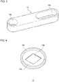
- Fig. 1 shows an appearance of an electric power tool 1 according to an embodiment of the present invention.
- the electric power tool 1 is provided with a main body 2 and a grip 3 gripped by an operator.
- the electric power tool 1 is provided with power from a secondary battery built in a detachable battery pack 4.
- a hammer drill in which the grip 3 is joined to the rear end of the main body 2 is illustrated by way of example of the electric power tool 1, but the electric power tool 1 may be other work tools such as a chipping machine.
- the longitudinal direction of the tool is defined such that the left side fitted with a front-end tool 9 is the tool front side, and the right side provided with the grip 3 is the tool rear side.
- the main body 2 is provided with a housing that at least houses a motor and a motion transmission mechanism for transmitting the rotational output of the motor to the front-end tool 9.
- the motion transmission mechanism is provided with an impact mechanism that transforms the rotational output of the motor decelerated by a deceleration mechanism into a reciprocal motion and transmits the reciprocal motion to the front-end tool 9, and a rotary mechanism that transmits the rotational output of the motor decelerated by the deceleration mechanism to the front-end tool 9.
- the grip 3 is provided with a trigger switch 8. When the operator pulls the trigger switch 8, the motor is supplied with power from the secondary battery and is driven into rotation, and the motion transmission mechanism transmits the rotational output of the motor to the front-end tool 9.
- the grip 3 has a handle 3a extending substantially perpendicular to the direction of the line of axis of the front-end tool 9, a lower extension 3b extending from the lower end of the handle 3a in a direction substantially parallel to the direction of the line of axis, and an upper extension 3c extending from the upper end of the handle 3a in a direction substantially parallel to the direction of the line of axis.
- the main body 2 and the grip 3 are configured as separate components.
- the grip 3 is joined to the rear side of the main body 2 by a first connector 5 and a second connector 7. Outside of the second connector 7 is provided a stretchable protection cover 6 to protect the second connector 7 from being exposed outside.
- the first connector 5 and the second connector 7 constitute a vibration control structure in the electric power tool 1.
- the first connector 5 rotatably joins the main body 2 and the grip 3.
- the first connector 5 may have a threaded member that rotatably joins the front end of the lower extension 3b and the lower part of the housing rear side of the main body 2.
- One first connector 5 is provided on left side of the electric power tool 1, and another first connector 5 is provided on right side of the electric power tool 1.
- Fig. 2 shows an example of the structure of the second connector 7.
- the second connector 7 is provided with a coil spring 12 as an elastic body provided between the main body 2 and the grip 3, and a guide rod 13 that maintains the direction of load on the coil spring 12 in alignment with the direction of the line of axis of the coil spring 12.
- the coil spring 12 is provided between the main body 2 and the grip 3 so as to be movable in coordination with the motion of the guide rod 13.
- the guide rod 13 has a role of aligning the direction of the line of axis of the coil spring 12 with the longitudinal direction of the guide rod 13.
- Fig. 3 shows an example of the guide rod 13.
- the guide rod 13 is a rod-shaped member made of a resin material and has a first opening 13a at one end and a second opening 13b at the other end.
- the second opening 13b is an elongated through hole extending in the longitudinal direction of the guide rod 13.
- the cross section of the elongated through hole is formed with a rectangular zone and two semicircular zones which are located at the longitudinal ends of the rectangular zone.
- the first opening 13a is formed as a through hole having a circular cross section.
- the upper part of the rear side of the main body 2 is provided with a cylindrical first rotation shaft 10 that extends in a transversal direction
- the front end of upper extension 3c is provided with a cylindrical second rotation shaft 11 that extends in a transversal direction.
- the main body 2 and the grip 3 are joined by the guide rod 13 so as to be rotatable relative to each other by inserting the first rotation shaft 10 into the first opening 13a of the guide rod 13 and inserting the second rotation shaft 11 into the second opening 13b of the guide rod 13.
- the second opening 13b is shaped such that the second rotation shaft 11 is slidable in the longitudinal direction of the guide rod 13.
- the second opening 13b is formed as an elongated through hole.
- the guide rod 13 is guided inside the coil spring 12 and is placed in alignment with the line of axis of the coil spring 12. This can make the second connector 7 compact.
- the guide rod 13 is provided with a first spring support 14a and a second spring support 14b.
- the coil spring 12 is supported by the first spring support 14a and the second spring support 14b.
- the first spring support 14a and the second spring support 14b have the same shape and will be referred to as "spring support 14" except when distinction is made.
- Fig. 4 shows an example of the spring support 14.
- the spring support 14 has a spring support surface 15a that the end of the coil spring 12 comes into contact with, a through hole 15b that the guide rod 13 is inserted through, and an annular rising portion 15c that rises from the outer circumference of the spring support surface 15a and prevents the lateral slip of the spring end.
- the first spring support 14a is thrust by the coil spring 12 to come into contact with the first rotation shaft 10
- the second spring support 14b is thrust by the coil spring 12 to come into contact with the second rotation shaft 11.
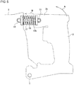
- Figs. 5 and 6 show the function of the vibration control structure according to the embodiment.
- the vibration control structure when vibration or shock impact is generated in the main body 2 while the operator is using the tool, the vibration control structure causes the grip 3 to be rotated in the direction indicated by the arrow A around the first connector 5.
- the guide rod 13 transforms the rotational motion of the grip 3 into linear motion in the direction indicated by the arrow B, i.e., the longitudinal direction of the guide rod 13, by sliding the second rotation shaft 11 in the second opening 13b.
- Fig. 6 shows a state in which the grip 3 is rotated relative to the main body 2 so as to be relatively closer. In the process in which the grip 3 approaches the main body 2, the vibration is absorbed by the coil spring 12.
- Fig. 6 shows a state in which the second rotation shaft 11 moves in the second opening 13b so as to compress the coil spring 12.
- the guide rod 13 always transforms the rotational motion of the grip 3 into linear motion in the direction indicated by the arrow B. Therefore, the direction of load applied to the coil spring 12 moving in coordination with the guide rod 13 is maintained in the direction of the arrow B, i.e., the direction of the line of axis of the coil spring 12.
- the coil spring 12 is compressed or stretched in the presence of a load in the direction of the line of axis so that the spring constant is maintained constant during compression or extraction.
- the vibration control structure capable of providing linear vibration absorption function is realized. Since the coil spring 12 does not receive a load obliquely relative to the direction of the line of axis, the life of the spring can be extended without deteriorating the spring property of the coil spring 12.
- the above-described advantage of the vibration control structure according to the embodiment will be appreciated more significantly when the electric power tool 1 is configured to be compact so that the interval between the first connector 5 and the second connector 7 is reduced.
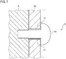
- Fig. 7 shows an example of the structure of the first connector 5.
- the lower part of the housing rear side of the main body 2 is provided with a threaded groove.
- a screw member 18 is inserted through a spacer 17 provided in a through hole of the lower extension 3b and tightened to the main body 2 accordingly.
- the spacer 17 may be made of an elastic material. By configuring the spacer 17 to be elastic, the first connector 5 is provided with the function of absorbing vibration.
- the second connector 7 in which the guide rod 13 is inserted inside the coil spring 12 and the guide rod 13 and the coil spring 12 are integrated with each other is shown.
- the guide rod 13 and the coil spring 12 may be separate on the condition that the guide rod 13 maintains the direction of load on the coil spring 12 to in alignment with the direction of the line of axis of the coil spring 12.
- a plurality of guide rods 13 may be provided or a plurality of coil springs 12 may be provided. Where a plurality of coil springs 12 are provided, it is preferable that the coil springs 12 be arranged in the transversal direction.
- the first rotation shaft 10 is inserted in the first opening 13a of the guide rod 13, and the second rotation shaft 11 is inserted in the second opening 13b of the guide rod 13.
- the second rotation shaft 11 may be inserted in the first opening 13a and the first rotation shaft 10 may be inserted in the second opening 13b.
- the second opening 13b is formed as an elongated through hole.
- both the first opening 13a and the second opening 13b may be formed as elongated through holes.
- the coil spring 12 is shown as exemplifying an elastic body. A spring different from the coil spring 12 may be used as an elastic body. Still alternatively, a rubber body made of a resin material may be used.
- An electric power tool (1) comprises: a main body (2) that houses a motor and a motion transmission mechanism for transmitting a rotational output of the motor to a front-end tool (9); and a grip (3) joined to a rear side of the main body by a first connector (5) and a second connector (7).
- the first connector (5) rotatably joins the main body (2) and the grip (3)
- the second connector (7) has an elastic body (12) provided between the main body (2) and the grip (3) and a guide rod (13) that maintains a direction of load on the elastic body in alignment with a direction of a line of axis of the elastic body.
- the guide rod (13) may have a first opening (13a) that a first rotation shaft (10) of the main body is inserted in and a second opening (13b) that a second rotation shaft (11) of the grip is inserted in, and the first opening or the second opening may be shaped such that the first rotation shaft or the second rotation shaft is slidable in a longitudinal direction of the guide rod.
- the first opening (13a) or the second opening (13b) may have a shape of an elongated hole extending in the longitudinal direction of the guide rod.
- the elastic body may be a coil spring (12) and the guide rod (13) may be inserted inside the coil spring (12).
- a pair of spring supports (14a, 14b) that support ends of the coil spring (12) may be provided in the guide rod (13), and the pair of spring supports may come into contact with the first rotation shaft (10) and the second rotation shaft (11), respectively.
Landscapes
- Engineering & Computer Science (AREA)
- Mechanical Engineering (AREA)
- Percussive Tools And Related Accessories (AREA)
- Portable Power Tools In General (AREA)
Applications Claiming Priority (1)
| Application Number | Priority Date | Filing Date | Title |
|---|---|---|---|
| JP2017050309A JP7001953B2 (ja) | 2017-03-15 | 2017-03-15 | ハンマドリル |
Publications (2)
| Publication Number | Publication Date |
|---|---|
| EP3375573A1 true EP3375573A1 (fr) | 2018-09-19 |
| EP3375573B1 EP3375573B1 (fr) | 2023-08-02 |
Family
ID=61256645
Family Applications (1)
| Application Number | Title | Priority Date | Filing Date |
|---|---|---|---|
| EP18157794.1A Active EP3375573B1 (fr) | 2017-03-15 | 2018-02-21 | Perceuse a percussion |
Country Status (2)
| Country | Link |
|---|---|
| EP (1) | EP3375573B1 (fr) |
| JP (1) | JP7001953B2 (fr) |
Families Citing this family (4)
| Publication number | Priority date | Publication date | Assignee | Title |
|---|---|---|---|---|
| JP7268395B2 (ja) * | 2019-02-25 | 2023-05-08 | 工機ホールディングス株式会社 | 打込機 |
| CN113993667A (zh) * | 2019-06-13 | 2022-01-28 | 工机控股株式会社 | 电动作业机 |
| US11883938B2 (en) * | 2019-06-26 | 2024-01-30 | Rhefor Gbr | Handheld setting tool |
| KR102576453B1 (ko) * | 2021-10-01 | 2023-09-12 | 계양전기 주식회사 | 전동공구의 충격완충장치 |
Citations (5)
| Publication number | Priority date | Publication date | Assignee | Title |
|---|---|---|---|---|
| US4749049A (en) * | 1983-04-02 | 1988-06-07 | Wacker-Werke Gmbh & Co. Kg | Hand-guided impact hammer and hammer drill |
| DE4124574A1 (de) * | 1991-07-24 | 1993-01-28 | Wolf Woco & Co Franz J | Griffisolierung |
| DE10236135A1 (de) * | 2002-08-07 | 2004-02-19 | Atlas Copco Electric Tools Gmbh | Werkzeug |
| JP2010000567A (ja) | 2008-06-19 | 2010-01-07 | Makita Corp | 手持式作業工具 |
| US20150129272A1 (en) * | 2012-07-06 | 2015-05-14 | Techtronic Power Tools Technology Limited | Power tool including an anti-vibration handle |
Family Cites Families (2)
| Publication number | Priority date | Publication date | Assignee | Title |
|---|---|---|---|---|
| JP2002096690A (ja) * | 2000-09-25 | 2002-04-02 | Sony Corp | リトラクト装置 |
| JP6558100B2 (ja) * | 2015-06-30 | 2019-08-14 | 工機ホールディングス株式会社 | 動力作業機 |
-
2017
- 2017-03-15 JP JP2017050309A patent/JP7001953B2/ja active Active
-
2018
- 2018-02-21 EP EP18157794.1A patent/EP3375573B1/fr active Active
Patent Citations (5)
| Publication number | Priority date | Publication date | Assignee | Title |
|---|---|---|---|---|
| US4749049A (en) * | 1983-04-02 | 1988-06-07 | Wacker-Werke Gmbh & Co. Kg | Hand-guided impact hammer and hammer drill |
| DE4124574A1 (de) * | 1991-07-24 | 1993-01-28 | Wolf Woco & Co Franz J | Griffisolierung |
| DE10236135A1 (de) * | 2002-08-07 | 2004-02-19 | Atlas Copco Electric Tools Gmbh | Werkzeug |
| JP2010000567A (ja) | 2008-06-19 | 2010-01-07 | Makita Corp | 手持式作業工具 |
| US20150129272A1 (en) * | 2012-07-06 | 2015-05-14 | Techtronic Power Tools Technology Limited | Power tool including an anti-vibration handle |
Also Published As
| Publication number | Publication date |
|---|---|
| JP7001953B2 (ja) | 2022-01-20 |
| EP3375573B1 (fr) | 2023-08-02 |
| JP2018153876A (ja) | 2018-10-04 |
Similar Documents
| Publication | Publication Date | Title |
|---|---|---|
| EP3375573A1 (fr) | Outil électrique | |
| EP2090393B1 (fr) | Outil électrique alternatif | |
| US3388728A (en) | Portable power tools | |
| EP3778085B1 (fr) | Dispositif de montage de lame de scie alternative et scie alternative | |
| US5711379A (en) | Hammer drill | |
| EP3568253B1 (fr) | Scie à va-et-vient | |
| EP2551060B1 (fr) | Outil électrique | |
| EP2415562A2 (fr) | Poignée arrière | |
| EP1529603A3 (fr) | Système limitant les vibrations pour outil électrique, et outil incorporant ce système | |
| WO2008043709A3 (fr) | Machine-outil portative, en particulier cisaille électrique | |
| EP2898994A1 (fr) | Outil électrique avec une poignée arrière | |
| EP1510298B1 (fr) | Outil électrique | |
| US20210129307A1 (en) | Reciprocating tool | |
| GB0325638D0 (en) | Vibration reduction apparatus for power tool and power tool incorporating such apparatus | |
| EP3381619B1 (fr) | Machine de travail à mouvement alternatif | |
| DE102018210553A1 (de) | Werkzeugmaschine | |
| US3816915A (en) | Stripping tools | |
| EP2415563B9 (fr) | Outil d'impact | |
| KR102208476B1 (ko) | 그라인더 전환용 드릴 어댑터 | |
| SE9900728D0 (sv) | Elhandverktygsmaskin | |
| US10632605B2 (en) | Work tool | |
| KR20120001182A (ko) | 전동톱 | |
| US1528731A (en) | Power-operated handsaw | |
| CN210732357U (zh) | 折弯工具及工具组合 | |
| EP2913157B1 (fr) | Dispositif de rétention de bits d'un outil d'installation d'un ancrage |
Legal Events
| Date | Code | Title | Description |
|---|---|---|---|
| PUAI | Public reference made under article 153(3) epc to a published international application that has entered the european phase |
Free format text: ORIGINAL CODE: 0009012 |
|
| STAA | Information on the status of an ep patent application or granted ep patent |
Free format text: STATUS: REQUEST FOR EXAMINATION WAS MADE |
|
| 17P | Request for examination filed |
Effective date: 20180221 |
|
| AK | Designated contracting states |
Kind code of ref document: A1 Designated state(s): AL AT BE BG CH CY CZ DE DK EE ES FI FR GB GR HR HU IE IS IT LI LT LU LV MC MK MT NL NO PL PT RO RS SE SI SK SM TR |
|
| AX | Request for extension of the european patent |
Extension state: BA ME |
|
| STAA | Information on the status of an ep patent application or granted ep patent |
Free format text: STATUS: EXAMINATION IS IN PROGRESS |
|
| 17Q | First examination report despatched |
Effective date: 20210526 |
|
| STAA | Information on the status of an ep patent application or granted ep patent |
Free format text: STATUS: EXAMINATION IS IN PROGRESS |
|
| GRAP | Despatch of communication of intention to grant a patent |
Free format text: ORIGINAL CODE: EPIDOSNIGR1 |
|
| STAA | Information on the status of an ep patent application or granted ep patent |
Free format text: STATUS: GRANT OF PATENT IS INTENDED |
|
| INTG | Intention to grant announced |
Effective date: 20230301 |
|
| GRAS | Grant fee paid |
Free format text: ORIGINAL CODE: EPIDOSNIGR3 |
|
| GRAA | (expected) grant |
Free format text: ORIGINAL CODE: 0009210 |
|
| STAA | Information on the status of an ep patent application or granted ep patent |
Free format text: STATUS: THE PATENT HAS BEEN GRANTED |
|
| AK | Designated contracting states |
Kind code of ref document: B1 Designated state(s): AL AT BE BG CH CY CZ DE DK EE ES FI FR GB GR HR HU IE IS IT LI LT LU LV MC MK MT NL NO PL PT RO RS SE SI SK SM TR |
|
| REG | Reference to a national code |
Ref country code: GB Ref legal event code: FG4D |
|
| REG | Reference to a national code |
Ref country code: CH Ref legal event code: EP |
|
| REG | Reference to a national code |
Ref country code: DE Ref legal event code: R096 Ref document number: 602018054378 Country of ref document: DE |
|
| REG | Reference to a national code |
Ref country code: IE Ref legal event code: FG4D |
|
| REG | Reference to a national code |
Ref country code: LT Ref legal event code: MG9D |
|
| REG | Reference to a national code |
Ref country code: NL Ref legal event code: MP Effective date: 20230802 |
|
| REG | Reference to a national code |
Ref country code: AT Ref legal event code: MK05 Ref document number: 1594145 Country of ref document: AT Kind code of ref document: T Effective date: 20230802 |
|
| PG25 | Lapsed in a contracting state [announced via postgrant information from national office to epo] |
Ref country code: GR Free format text: LAPSE BECAUSE OF FAILURE TO SUBMIT A TRANSLATION OF THE DESCRIPTION OR TO PAY THE FEE WITHIN THE PRESCRIBED TIME-LIMIT Effective date: 20231103 |
|
| PG25 | Lapsed in a contracting state [announced via postgrant information from national office to epo] |
Ref country code: IS Free format text: LAPSE BECAUSE OF FAILURE TO SUBMIT A TRANSLATION OF THE DESCRIPTION OR TO PAY THE FEE WITHIN THE PRESCRIBED TIME-LIMIT Effective date: 20231202 |
|
| PG25 | Lapsed in a contracting state [announced via postgrant information from national office to epo] |
Ref country code: SE Free format text: LAPSE BECAUSE OF FAILURE TO SUBMIT A TRANSLATION OF THE DESCRIPTION OR TO PAY THE FEE WITHIN THE PRESCRIBED TIME-LIMIT Effective date: 20230802 Ref country code: RS Free format text: LAPSE BECAUSE OF FAILURE TO SUBMIT A TRANSLATION OF THE DESCRIPTION OR TO PAY THE FEE WITHIN THE PRESCRIBED TIME-LIMIT Effective date: 20230802 Ref country code: PT Free format text: LAPSE BECAUSE OF FAILURE TO SUBMIT A TRANSLATION OF THE DESCRIPTION OR TO PAY THE FEE WITHIN THE PRESCRIBED TIME-LIMIT Effective date: 20231204 Ref country code: NO Free format text: LAPSE BECAUSE OF FAILURE TO SUBMIT A TRANSLATION OF THE DESCRIPTION OR TO PAY THE FEE WITHIN THE PRESCRIBED TIME-LIMIT Effective date: 20231102 Ref country code: NL Free format text: LAPSE BECAUSE OF FAILURE TO SUBMIT A TRANSLATION OF THE DESCRIPTION OR TO PAY THE FEE WITHIN THE PRESCRIBED TIME-LIMIT Effective date: 20230802 Ref country code: LV Free format text: LAPSE BECAUSE OF FAILURE TO SUBMIT A TRANSLATION OF THE DESCRIPTION OR TO PAY THE FEE WITHIN THE PRESCRIBED TIME-LIMIT Effective date: 20230802 Ref country code: LT Free format text: LAPSE BECAUSE OF FAILURE TO SUBMIT A TRANSLATION OF THE DESCRIPTION OR TO PAY THE FEE WITHIN THE PRESCRIBED TIME-LIMIT Effective date: 20230802 Ref country code: IS Free format text: LAPSE BECAUSE OF FAILURE TO SUBMIT A TRANSLATION OF THE DESCRIPTION OR TO PAY THE FEE WITHIN THE PRESCRIBED TIME-LIMIT Effective date: 20231202 Ref country code: HR Free format text: LAPSE BECAUSE OF FAILURE TO SUBMIT A TRANSLATION OF THE DESCRIPTION OR TO PAY THE FEE WITHIN THE PRESCRIBED TIME-LIMIT Effective date: 20230802 Ref country code: GR Free format text: LAPSE BECAUSE OF FAILURE TO SUBMIT A TRANSLATION OF THE DESCRIPTION OR TO PAY THE FEE WITHIN THE PRESCRIBED TIME-LIMIT Effective date: 20231103 Ref country code: FI Free format text: LAPSE BECAUSE OF FAILURE TO SUBMIT A TRANSLATION OF THE DESCRIPTION OR TO PAY THE FEE WITHIN THE PRESCRIBED TIME-LIMIT Effective date: 20230802 Ref country code: AT Free format text: LAPSE BECAUSE OF FAILURE TO SUBMIT A TRANSLATION OF THE DESCRIPTION OR TO PAY THE FEE WITHIN THE PRESCRIBED TIME-LIMIT Effective date: 20230802 |
|
| PG25 | Lapsed in a contracting state [announced via postgrant information from national office to epo] |
Ref country code: PL Free format text: LAPSE BECAUSE OF FAILURE TO SUBMIT A TRANSLATION OF THE DESCRIPTION OR TO PAY THE FEE WITHIN THE PRESCRIBED TIME-LIMIT Effective date: 20230802 |
|
| PG25 | Lapsed in a contracting state [announced via postgrant information from national office to epo] |
Ref country code: ES Free format text: LAPSE BECAUSE OF FAILURE TO SUBMIT A TRANSLATION OF THE DESCRIPTION OR TO PAY THE FEE WITHIN THE PRESCRIBED TIME-LIMIT Effective date: 20230802 |
|
| PG25 | Lapsed in a contracting state [announced via postgrant information from national office to epo] |
Ref country code: SM Free format text: LAPSE BECAUSE OF FAILURE TO SUBMIT A TRANSLATION OF THE DESCRIPTION OR TO PAY THE FEE WITHIN THE PRESCRIBED TIME-LIMIT Effective date: 20230802 Ref country code: RO Free format text: LAPSE BECAUSE OF FAILURE TO SUBMIT A TRANSLATION OF THE DESCRIPTION OR TO PAY THE FEE WITHIN THE PRESCRIBED TIME-LIMIT Effective date: 20230802 Ref country code: ES Free format text: LAPSE BECAUSE OF FAILURE TO SUBMIT A TRANSLATION OF THE DESCRIPTION OR TO PAY THE FEE WITHIN THE PRESCRIBED TIME-LIMIT Effective date: 20230802 Ref country code: EE Free format text: LAPSE BECAUSE OF FAILURE TO SUBMIT A TRANSLATION OF THE DESCRIPTION OR TO PAY THE FEE WITHIN THE PRESCRIBED TIME-LIMIT Effective date: 20230802 Ref country code: DK Free format text: LAPSE BECAUSE OF FAILURE TO SUBMIT A TRANSLATION OF THE DESCRIPTION OR TO PAY THE FEE WITHIN THE PRESCRIBED TIME-LIMIT Effective date: 20230802 Ref country code: CZ Free format text: LAPSE BECAUSE OF FAILURE TO SUBMIT A TRANSLATION OF THE DESCRIPTION OR TO PAY THE FEE WITHIN THE PRESCRIBED TIME-LIMIT Effective date: 20230802 Ref country code: SK Free format text: LAPSE BECAUSE OF FAILURE TO SUBMIT A TRANSLATION OF THE DESCRIPTION OR TO PAY THE FEE WITHIN THE PRESCRIBED TIME-LIMIT Effective date: 20230802 |
|
| PGFP | Annual fee paid to national office [announced via postgrant information from national office to epo] |
Ref country code: DE Payment date: 20240219 Year of fee payment: 7 |