EP3375005B1 - Method for assembly of a cathode for an x-ray tube - Google Patents
Method for assembly of a cathode for an x-ray tube Download PDFInfo
- Publication number
- EP3375005B1 EP3375005B1 EP16790930.8A EP16790930A EP3375005B1 EP 3375005 B1 EP3375005 B1 EP 3375005B1 EP 16790930 A EP16790930 A EP 16790930A EP 3375005 B1 EP3375005 B1 EP 3375005B1
- Authority
- EP
- European Patent Office
- Prior art keywords
- filament
- cathode
- helical
- machining
- support structures
- Prior art date
- Legal status (The legal status is an assumption and is not a legal conclusion. Google has not performed a legal analysis and makes no representation as to the accuracy of the status listed.)
- Active
Links
- 238000000034 method Methods 0.000 title claims description 29
- 238000003754 machining Methods 0.000 claims description 25
- 239000000919 ceramic Substances 0.000 claims description 11
- 238000009760 electrical discharge machining Methods 0.000 claims description 11
- 238000005476 soldering Methods 0.000 claims description 8
- 238000004804 winding Methods 0.000 claims description 7
- 230000009471 action Effects 0.000 claims description 5
- 239000011248 coating agent Substances 0.000 claims description 5
- 238000000576 coating method Methods 0.000 claims description 5
- 238000001953 recrystallisation Methods 0.000 description 11
- 230000008901 benefit Effects 0.000 description 8
- 230000007246 mechanism Effects 0.000 description 7
- 238000003384 imaging method Methods 0.000 description 5
- 238000007689 inspection Methods 0.000 description 5
- JLDSOYXADOWAKB-UHFFFAOYSA-N aluminium nitrate Chemical compound [Al+3].[O-][N+]([O-])=O.[O-][N+]([O-])=O.[O-][N+]([O-])=O JLDSOYXADOWAKB-UHFFFAOYSA-N 0.000 description 4
- 238000005219 brazing Methods 0.000 description 4
- 230000001419 dependent effect Effects 0.000 description 4
- 238000002059 diagnostic imaging Methods 0.000 description 4
- 230000008859 change Effects 0.000 description 3
- 239000000463 material Substances 0.000 description 3
- 230000008569 process Effects 0.000 description 3
- 238000012216 screening Methods 0.000 description 3
- 238000010276 construction Methods 0.000 description 2
- 238000009826 distribution Methods 0.000 description 2
- 238000004519 manufacturing process Methods 0.000 description 2
- 230000005855 radiation Effects 0.000 description 2
- 230000009467 reduction Effects 0.000 description 2
- 238000007669 thermal treatment Methods 0.000 description 2
- 230000004075 alteration Effects 0.000 description 1
- 238000010292 electrical insulation Methods 0.000 description 1
- 238000010894 electron beam technology Methods 0.000 description 1
- 238000005421 electrostatic potential Methods 0.000 description 1
- 239000012212 insulator Substances 0.000 description 1
- 238000001465 metallisation Methods 0.000 description 1
- 238000012806 monitoring device Methods 0.000 description 1
- 230000003287 optical effect Effects 0.000 description 1
- TWNQGVIAIRXVLR-UHFFFAOYSA-N oxo(oxoalumanyloxy)alumane Chemical compound O=[Al]O[Al]=O TWNQGVIAIRXVLR-UHFFFAOYSA-N 0.000 description 1
- 230000000087 stabilizing effect Effects 0.000 description 1
- 238000009763 wire-cut EDM Methods 0.000 description 1
Images


Classifications
-
- G—PHYSICS
- G01—MEASURING; TESTING
- G01N—INVESTIGATING OR ANALYSING MATERIALS BY DETERMINING THEIR CHEMICAL OR PHYSICAL PROPERTIES
- G01N23/00—Investigating or analysing materials by the use of wave or particle radiation, e.g. X-rays or neutrons, not covered by groups G01N3/00 – G01N17/00, G01N21/00 or G01N22/00
- G01N23/02—Investigating or analysing materials by the use of wave or particle radiation, e.g. X-rays or neutrons, not covered by groups G01N3/00 – G01N17/00, G01N21/00 or G01N22/00 by transmitting the radiation through the material
- G01N23/04—Investigating or analysing materials by the use of wave or particle radiation, e.g. X-rays or neutrons, not covered by groups G01N3/00 – G01N17/00, G01N21/00 or G01N22/00 by transmitting the radiation through the material and forming images of the material
-
- H—ELECTRICITY
- H01—ELECTRIC ELEMENTS
- H01J—ELECTRIC DISCHARGE TUBES OR DISCHARGE LAMPS
- H01J35/00—X-ray tubes
- H01J35/02—Details
- H01J35/04—Electrodes ; Mutual position thereof; Constructional adaptations therefor
- H01J35/06—Cathodes
- H01J35/066—Details of electron optical components, e.g. cathode cups
-
- H—ELECTRICITY
- H01—ELECTRIC ELEMENTS
- H01J—ELECTRIC DISCHARGE TUBES OR DISCHARGE LAMPS
- H01J9/00—Apparatus or processes specially adapted for the manufacture, installation, removal, maintenance of electric discharge tubes, discharge lamps, or parts thereof; Recovery of material from discharge tubes or lamps
- H01J9/02—Manufacture of electrodes or electrode systems
- H01J9/18—Assembling together the component parts of electrode systems
Definitions
- the present invention relates to a method for assembly of a cathode for an X-ray tube.
- a filament for emitting electrons to impinge on a surface, thereby generating X-ray radiation.
- the exact arrangement of the filament and its positioning within an optical system is required. Alterations of the filament during operation may lead to a change of the focal spot and thus to a change of the radiated X-ray beam. Therefore, care is taken for a correct positioning of the filament during assembly. For example, during a cathode cup assembly, the required filament shape and also the position of the filament in relation to the cathode head takes place with a predefined accuracy. This is achieved, for example, by manual adjustment.
- US 6,607,416 B2 describes a fixture for using a mandril to set a filament on an electrode for mounting the filament on a cathode head.
- a mandril to set a filament on an electrode for mounting the filament on a cathode head.
- the securing of the filament ends in the cavities of the cathode may still require final position relating to the direction of the emitted electrons.
- the correct alignment of the mounting tool in relation to the cathode cup for properly positioning the filament in the first place has to be carefully monitored.
- WO 2013/175402A1 discloses a cathode for an X-ray tube with an improved and facilitated assembly. This document discloses that the filament is totally recrystallized.
- US 5 526 396 A discloses an X-ray tube, comprising a cathode arrangement including a filament, wherein simple adjustment of the position of the filament is achieved.
- JP 53-132983A discloses an X-ray tube and it's prodcution method avoiding the irregularity of X-ray focus shapes with preventing a filament from rotating and moving by providing the cut face of the support bar arrangement direction in two clyndrical filament support bars and fixing the filament to this cut face.
- a method for assembly of a cathode for an X-ray tube comprises the following steps:
- the filament has a complete helical structure extending from one end of the filament to the other end of the filament.
- the machining is electrical discharge machining. This has the advantage that the machining of the crucial parts of the cathode can be performed with high precision and reproducibility. Furthermore, the surface and edge conditions can be chosen in order to match the needs of a cathode head.
- the total recrystallization of the filament is provided by applying external heat.
- the total recrystallization is thus not provided by an electric current applied to the two ends of the cathode to generate heat from inside, but rather by heat from outside of the filament, for example in an oven or furnace.
- the total recrystallization process is performed in advance. It is not important how the recrystallization is achieved but only that the filament shows the total recrystallization property before assembly. Hence the total recrystallization may be achieved by any suitable method.
- flashing refers to an application of a high current in order to let the filament glow for a predetermined short period of time.
- flashing provides a thermal treatment with the purpose of stabilizing the filament. This process is hard to control due to residual stress that can lead to warping of the filament.
- a totally recrystallized filament will have reduced plastic deformation over lifetime and an improved lifetime distribution by a reduction of failure modes.
- a successful assembly is defined by the precision of position and orientation of the filament within the narrow slit of the recess or cavity (in operation, over time).
- the present invention suggests the fabrication of a cathode cup with braced supporting wires that exhibit high precision slots for the filament within the already machined recess and notches. Notably, the brazing of the supporting structures leads to a particular robust connection in operation.
- This intermediate cathode cup without filament can be manufactured in different ways. A possibility including one machining step was described above. Machining is done by electrical discharge machining (EDM), preferably wire cut EDM.
- the supporting structures are brazed in a cathode cup without recess. Afterwards, the notches in the supporting structures for the filament as well as the recess in the cathode head are machined in a single EDM step providing automatically perfect orientation. Finally, the filament is attached (typically laser welded or just by clicking it into the notch).
- the recess is machined by EDM in a cathode cup body structure without supporting structures. Subsequently, the supporting structures are brazed into the body structure, showing no notch at that step. Afterwards, the notches for the filament are machined into the supporting structures with a second EDM step. Both steps have to be aligned precisely. This can be achieved by performing both EDM steps on a single machine with the same reception. Again, the filament is inserted or attached at last. For above possibilities, the filament is precisely manufactured and thermally treated to avoid contour changes in operation at high temperatures. This is done by total recrystallization of the filament material in advance.
- the support of the filament can be directly brazed to the cathode or ceramic insulator and cathode with potentially higher thermal and mechanical loadability of the cathode by increased stability and less thermal drift with shorter elements and more direct connections.
- the method provides a cathode for an X-ray tube, comprising a filament, at least two support structures, a body structure comprising a recess for the filament.
- the filament is provided to emit electrons towards an anode in an electron emitting direction.
- the filament is held by the support structures, which are fixedly connected to the body structure.
- the filament is totally recrystallized.
- the support structures comprise a reception end for releasably receiving two ends of the filament by means of a locking mechanism and the alignment of the filament and the recess is given by the geometry of the filament, the at least two support structures and the body structure comprising a recess for the filament.
- the filament exhibits a helical structure that serves as the electron emitting surfaces in operation and ending parts that serve as counter pieces to reception ends of the support structures.
- electron emitting direction relates to the main direction of electrons as defined by a line connecting a central portion of the filament with a central portion of a focal spot on the anode.
- the core idea of the invention is to avoid state-of-the-art alignment steps in the assembly procedure by using components fabricated with high precision at the crucial regions and removing inherent stress through thermal treatment of the components.
- the state of the art assembly procedure there may be as many as 20 steps including alignment of the filament.
- this number is reduced to about 5 steps and no further alignment steps are required because of the inherent manufacturing precision of the proposed cathode structure.
- the filament is already totally recrystallized, no misalignment of the filament occurs due to recrystallization. Apart from the advantage that there is reduced plastic deformation over lifetime an improved lifetime distribution by a reduction of failure modes during operation is achieved.
- the filament has a complete helical structure extending from one end of the filament to the other end of the filament.
- the whole filament may have helical structure that can be releasably received by appropriate reception ends of the support structures by means of a locking mechanism.
- the filament has a helical structure extending from one end of the filament to the other end of the filament.
- the support structures comprise a reception end for releasably receiving two helical ends of the helical structure by means of a locking mechanism. Because the total filament has a helical structure the alignment is per definition correct with respect to the reception ends of the support structures. There are no non-helical ends of the filament which may cause misalignment.
- the longitudinal direction around which the helical winding of the filament is provided is substantially straight. Thus, any susceptibility to change in the length of the helical winding is avoided.
- the middle portion of the helical structure has a first helical pitch and the helical ends of the helical structure have a second helical pitch.
- the second helical pitch may e.g. be larger than the first helical pitch.
- the locking mechanism of the support structure comprises a notch. This has the advantage of easy assembly of the helical winding, possibly without the need for additional soldering steps and a good mechanical stability.
- the support and filament are laser welded.
- the notch has a geometrical shape to firmly receive the helical ends without mechanical play.
- Different notch shapes can be envisaged like 3 ⁇ 4 cylinder, half cylinder, trough, rectangle, sideway 3 ⁇ 4 cylinder, tapered 3 ⁇ 4 cylinder, 3g: thin 3 ⁇ 4 cylinder.
- pretension of the filament is not necessary since the helical geometry of the filament can absorb the tension originating from thermal expansion during operation.
- the connection to the rigid support structure helps to avoid distortion compared to state-of-the-art filament geometries as in Fig. 1b .
- the body structure is provided as a cathode cup comprising a recess in comprising the filament which is fixedly held.
- the cathode cup is provided with at least two filaments facing the anode.
- the cathode cup is provided as a ceramic cathode cup made from electrically non-conducting ceramic and wherein a part of the cathode cup's surfaces is provided with a metallic coating.
- non-conducting means electrically insolating.
- the metallic coating is also referred to as a metalized surface.
- the metallic coating is provided for electric conducting purposes, and for brazing purposes.
- the cathode cup is made from aluminium oxide (Al 2 O 3 ).
- the cathode may also be made from aluminium nitrate (AlN).
- an X-ray tube comprising a cathode and an anode.
- the cathode is provided as a cathode obtained by the method according to one of the above mentioned examples.
- a system for X-ray imaging comprising an X-ray source, an X-ray detector, and a processing unit.
- the processing unit is configured to control the X-ray source and the X-ray detector for providing X-ray image data of an object of interest.
- the X-ray source is provided with an X-ray tube as described and discussed above.
- the X-ray system may be a medical imaging system.
- an inspection apparatus is provided as the X-ray system, for example for scanning and screening of luggage or transportation pieces, or for material and construction inspection purposes.
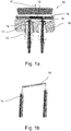
- Fig. 1a shows a cross sectional view of a known cathode 10 for an X-ray tube.
- the cathode 10 comprises a filament 12, a support structure 14, and a body structure 16.
- the support structure 14 comprises a first mounting bolt 17 and a second bolt 18.
- Ceramics 13 for electrical insulation of filament and cathode head 10 are shown for two supports per filament but can also be used for a single support wire only.
- the filament 12 is provided to emit electrons towards an anode (not shown) in an electron emitting direction 11. For electron-optical reasons the filament is precisely positioned within a recess 15.
- the filament 12 at least partially comprises a helical structure.
- the filament 12 is held by the support structure 14, which is fixedly connected to the body structure 16.
- Fig. 1b shows that the filament 12 is held by the support structure 14.
- the mounting bolts extending through the body structure 16 can have a respective connection at the side opposite to the side where the filament 12 is arranged.
- An electrical source provides the electrical current to the filament 12 (not further shown).
- a filament 22 and two support structures 21 are shown in a perspective view.
- Fig. 2b and 2c two embodiments of filaments are shown.
- the filament and two support structures are present in a body structure (not shown).
- the filament is provided to emit electrons towards an anode in an electron emitting direction 25.
- the filament is held by the support structures 21, which are fixedly connected to the body structure.
- the filament has a helical structure (22, 23) extending from one end of the filament to the other end of the filament; and the support structures 21 comprise a reception end 24 for releasably receiving two helical ends of the helical structure 22 by means of a locking mechanism.
- the longitudinal direction around which the helical winding of the filament is provided is substantially straight.
- the middle portion of the helical structure 22 has a first helical pitch and the helical ends 23 of the helical structure have a second helical pitch.
- the second helical pitch is larger than the first helical pitch.
- the locking mechanism of the support structure comprises a notch.
- the notch has a geometrical shape to firmly receive the helical ends without mechanical play.
- FIGs. 3a to 3g 7 different kinds of notches are shown to accommodate the ends of the helical structure.
- 3a is a click notch
- 3b is a half cylinder notch
- 3c is a trough notch
- 3d is a rectangle notch
- 3e is a sideway click notch
- 3f is a tapered click notch
- 3g is a thin click notch
- 3h is narrow notch for receiving a straight wire end of a at least partially helical filament which exhibits a helical winding structure and straight wires as legs parallel to the longitudinal direction around which the helical winding of the filament is provided.
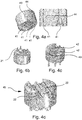
- FIG. 4a left shows a perspective view of a body structure 40 of cathode cup with four support structure holes 41.
- Fig. 4a right shows a cross section through two support structure holes for inserting support structures for receiving a filament.
- Fig. 4b the body structure of a cathode cup is shown after inserting and soldering four support structures 21 in the support structure holes 41.
- Fig. 4a left shows a perspective view of a body structure 40 of cathode cup with four support structure holes 41.
- Fig. 4a right shows a cross section through two support structure holes for inserting support structures for receiving a
- the body structure of the cathode cup is shown after machining two recesses 42 by wire cut electrical discharge machining (EDM), forming two filament spaces 42, into the cathode cup.
- EDM electrical discharge machining
- the cathode cup is shown wherein in the same machining action as machining the recesses machining the support structures 21 are machined by forming a notch 43 at a reception end of each of the support structures to receive the ends of a helical filament.
- a horizontal bore 44 allows for a single (EDM) machining step that cuts both the cavity in the head 40 and the reception in the support structures 21.
- the ready cathode cup 45 is shown after inserting each of four ends of two filaments 22 as described with Fig. 2c into each of the notches of the support structures 21. Thus in total two such filaments are inserted.
- the figures show only one ceramic per filament. There can be a higher number and different types of ceramics.
- FIGs 5a to 5d according to an example useful for understanding the present invention, four drawings are shown which represent the assembly status of a cathode when a method for assembly of a cathode for an X-ray tube is performed.
- a body structure 40 of a cathode cup is show with four support structure holes after machining two recesses 42, forming filament spaces, into the cathode cup.
- the horizontal bore 44 is not necessary in this embodiment.
- Fig. 5b the body structure of the cathode cup is shown after inserting and soldering four support structures 21 in the support structure holes.
- Fig. 5a body structure 40 of a cathode cup is show with four support structure holes after machining two recesses 42, forming filament spaces, into the cathode cup.
- the horizontal bore 44 is not necessary in this embodiment.
- Fig. 5b the body structure of the cathode cup is shown after inserting and soldering four support structures 21 in the support structure holes.
- the body structure of the cathode cup is shown after machining the support structures by forming a notch at the top of each of the support structures 21 to receive the end of a helical filament.
- the ready cathode cup 45 is shown after inserting each of 4 ends of two filaments 22, as described with Fig.2c , into each of the notches of the support structures 21.
- Fig. 5d additionally shows a close up of the support structure end with notch and inserted filament.
- the order of two steps is reversed so that the machining steps of machining the recesses and machining the support structures are not performed in one action but after inserting and soldering the support structures.
- the machining is also EDM.
- the mounting bolts of the support structure 21 are extending through the body structure 41. Therefore, a stepped through-hole 41 is provided with an upper portion having a larger diameter than the lower portion corresponding to either the diameter of the mounting bolt or the ceramic.
- the brazing e.g. high temperature soldering
- the bolts are not coupled to the body structure 41 allowing for high thermal loads of the filament core while thermally protecting the brazed connection.
- the filament 22 is totally recrystallized, to achieve required straightness in operation over time.
- the filament 22 is made of W.
- a cylindrical shaped guiding pin may be provided inserted into the helical structure during the recrystallization.
- the cathode is provided as a cathode cup, for example the cathode cup 45.
- the cathode cup may be provided as a ceramic cathode cup, made from electrically non-conducting ceramic. A part of the cathode cup's surfaces is provided with a metallic coating.
- the metallization is provided on the surfaces for brazing and electrical purposes, e.g. to avoid surface charges.
- Fig. 6 shows an X-ray tube 100 comprising a cathode 110, and an anode 112.
- the cathode is provided as a cathode according to one of the above mentioned and described examples.
- the X-ray tube is provided with a rotating anode 112, indicated with a rotation axis 114.
- driving device 116 is indicated, whereas only the parts inside a tube housing 118 are shown, neglecting any parts being outside, for example a scatter of the driving means.
- steering or deflection means device 120 is shown for deflecting an electron beam 122 from the cathode 110 towards a focal spot portion 124 on the anode 112.
- An X-ray transparent window 126 is shown such that an X-ray beam 128 is radiated towards a not further shown object.
- Fig. 6 is a schematic drawing of an X-ray tube.
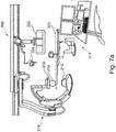
- a system 200 for X-ray imaging comprising an X-ray source 210, and X-ray detector 212, and a processing unit 214.
- the processing unit 214 is configured to control the X-ray source 210 and the X-ray detector 212 for providing X-ray image data of an object of interest 216.
- the X-ray source 210 is provided as an X-ray tube 100 according to the above mentioned example.
- the X-ray system may be a medical imaging system as shown in Fig. 7a .
- the X-ray source 210 and the X-ray detector 212 are provided as a so-called C-arm arrangement 218, where a C-arm structure is movably mounted to a support arrangement in order to provide free arrangement of the source and detector around the object of interest.
- a patient table as well as monitoring devices 222 and lighting devices 224 are shown indicating an operational room in a hospital.
- the X-ray system may be any other medical imaging system in which an X-ray source including a cathode according to the invention is used, e.g. a CT X-ray imaging system.
- an inspection apparatus 226 is provided, for example for scanning and screening of luggage pieces 228, or for material and construction inspection.
- This is shown in Fig. 7b as a further example for an X-ray system 200 for X-ray imaging, comprising an X-ray source which is provided as an X-ray tube according to the above mentioned examples. It is noted that the X-ray source is not further shown in Fig. 7b .
- Fig. 8 shows a method 300 for an assembly of a cathode for an X-ray tube, comprising the following steps: a) providing (310) a cathode cup with at least two support structure holes; b) inserting and soldering (312) at least two support structures in the support structure holes; c) machining a recess (314), forming a filament space, into the cathode cup; d) in the same machining action as c) machining the support structures (314) by forming a notch at the top of each of the support structures to receive the end of a helical filament; and e) inserting (316) each end of a totally recrystallized filament, having at least a partial helical structure, into each of the notches of the support structures.
- the filament has a complete helical structure (22, 23) extending from one end of the filament to the other end of the filament.
- the filament is configured to emit electrons towards an anode in an electron emitting direction.
- the total recrystallization of the filament is provided by applying external heat.
Landscapes
- Engineering & Computer Science (AREA)
- Manufacturing & Machinery (AREA)
- Physics & Mathematics (AREA)
- Health & Medical Sciences (AREA)
- Life Sciences & Earth Sciences (AREA)
- Chemical & Material Sciences (AREA)
- Analytical Chemistry (AREA)
- Biochemistry (AREA)
- General Health & Medical Sciences (AREA)
- General Physics & Mathematics (AREA)
- Immunology (AREA)
- Pathology (AREA)
- X-Ray Techniques (AREA)
Applications Claiming Priority (2)
| Application Number | Priority Date | Filing Date | Title |
|---|---|---|---|
| EP15194511 | 2015-11-13 | ||
| PCT/EP2016/076005 WO2017080843A1 (en) | 2015-11-13 | 2016-10-28 | Cathode for an x-ray tube |
Publications (2)
| Publication Number | Publication Date |
|---|---|
| EP3375005A1 EP3375005A1 (en) | 2018-09-19 |
| EP3375005B1 true EP3375005B1 (en) | 2019-09-25 |
Family
ID=54544972
Family Applications (1)
| Application Number | Title | Priority Date | Filing Date |
|---|---|---|---|
| EP16790930.8A Active EP3375005B1 (en) | 2015-11-13 | 2016-10-28 | Method for assembly of a cathode for an x-ray tube |
Country Status (5)
| Country | Link |
|---|---|
| US (1) | US11232926B2 (enExample) |
| EP (1) | EP3375005B1 (enExample) |
| JP (1) | JP7092664B2 (enExample) |
| CN (1) | CN108352282B (enExample) |
| WO (1) | WO2017080843A1 (enExample) |
Families Citing this family (8)
| Publication number | Priority date | Publication date | Assignee | Title |
|---|---|---|---|---|
| WO2019192686A1 (en) * | 2018-04-04 | 2019-10-10 | Comet Ag | Easy-to-install cathode geometry for x-ray tubes |
| KR102448410B1 (ko) * | 2018-11-28 | 2022-09-28 | 주식회사 레메디 | 추출기를 가지는 소형 엑스레이 튜브 |
| WO2021127858A1 (en) * | 2019-12-23 | 2021-07-01 | Shenzhen United Imaging Healthcare Co., Ltd. | Radiotherapy device and microwave source thereof |
| CN112786418B (zh) * | 2021-01-29 | 2024-06-21 | 成都宏明电子股份有限公司 | 一种高效抗振的离子源灯丝组件及其制造方法 |
| CN113838728B (zh) * | 2021-09-03 | 2024-03-26 | 奕瑞影像科技成都有限公司 | 一种离子源灯丝组件及其焊接方法 |
| CN114999871B (zh) * | 2022-04-26 | 2024-07-16 | 核工业理化工程研究院 | 一种高可靠性的蚊香型灯丝锁紧结构及其锁紧方法 |
| US12119201B2 (en) | 2022-09-15 | 2024-10-15 | Elve Inc. | Cathode heater assembly and method of manufacture |
| CN118645414B (zh) * | 2024-08-15 | 2025-01-03 | 昆山医源医疗技术有限公司 | 用于x射线管的阴极组件及x射线管 |
Family Cites Families (16)
| Publication number | Priority date | Publication date | Assignee | Title |
|---|---|---|---|---|
| CH542510A (de) | 1971-12-27 | 1973-09-30 | Siemens Ag | Röntgenröhre |
| US3875028A (en) * | 1972-08-30 | 1975-04-01 | Picker Corp | Method of manufacture of x-ray tube having focusing cup with non emitting coating |
| JPS6019096B2 (ja) * | 1977-04-26 | 1985-05-14 | 株式会社東芝 | X線管用陰極の製造方法 |
| FR2650703B1 (fr) | 1989-08-07 | 1991-10-11 | Gen Electric Cgr | Cathode de tube a rayons x et tube ainsi obtenu |
| JPH0769051B2 (ja) | 1990-06-19 | 1995-07-26 | 品川白煉瓦株式会社 | バーナータイル |
| DE4021709A1 (de) | 1990-07-07 | 1992-01-09 | Philips Patentverwaltung | Elektronenroehre mit einer kathodenanordnung, die eine heizdrahtwendel umfasst |
| KR920008501Y1 (ko) | 1990-11-27 | 1992-11-30 | 삼성전관 주식회사 | 초소형 음극선관용 직열형 음극구조체 |
| JPH069047U (ja) * | 1992-07-03 | 1994-02-04 | 株式会社日立メディコ | X線管 |
| FR2699326B1 (fr) | 1992-12-11 | 1995-01-06 | Gen Electric Cgr | Emetteur électronique d'un tube à rayons X. |
| DE4325609A1 (de) * | 1993-07-30 | 1995-02-02 | Philips Patentverwaltung | Elektronenröhre |
| US6607416B2 (en) | 2001-06-08 | 2003-08-19 | Koninklijke Philips Electronics N.V. | Method and apparatus for setting X-ray tube filaments |
| US7327829B2 (en) | 2004-04-20 | 2008-02-05 | Varian Medical Systems Technologies, Inc. | Cathode assembly |
| US20100040201A1 (en) * | 2008-08-14 | 2010-02-18 | Varian Medical Systems, Inc. | Cathode with a Coating Near the Filament and Methods for Making Same |
| US8451976B2 (en) * | 2010-07-30 | 2013-05-28 | Varian Medical Systems, Inc. | Cathode assembly for an X-ray tube |
| WO2013175402A1 (en) | 2012-05-22 | 2013-11-28 | Koninklijke Philips N.V. | Cathode filament assembly |
| US9779907B2 (en) * | 2015-01-28 | 2017-10-03 | Varex Imaging Corporation | X-ray tube having a dual grid and dual filament cathode |
-
2016
- 2016-10-28 CN CN201680066052.6A patent/CN108352282B/zh active Active
- 2016-10-28 EP EP16790930.8A patent/EP3375005B1/en active Active
- 2016-10-28 JP JP2018524333A patent/JP7092664B2/ja active Active
- 2016-10-28 WO PCT/EP2016/076005 patent/WO2017080843A1/en not_active Ceased
- 2016-10-28 US US15/775,636 patent/US11232926B2/en active Active
Non-Patent Citations (1)
| Title |
|---|
| None * |
Also Published As
| Publication number | Publication date |
|---|---|
| CN108352282A (zh) | 2018-07-31 |
| US20180350550A1 (en) | 2018-12-06 |
| JP2019501483A (ja) | 2019-01-17 |
| JP7092664B2 (ja) | 2022-06-28 |
| US11232926B2 (en) | 2022-01-25 |
| CN108352282B (zh) | 2020-05-22 |
| EP3375005A1 (en) | 2018-09-19 |
| WO2017080843A1 (en) | 2017-05-18 |
Similar Documents
| Publication | Publication Date | Title |
|---|---|---|
| EP3375005B1 (en) | Method for assembly of a cathode for an x-ray tube | |
| EP2852964B1 (en) | Cathode filament assembly | |
| DE69415966T2 (de) | Gasentladungsröhre | |
| EP2851929B1 (en) | A X-Ray apparatus and a CT device having the same | |
| US9824847B2 (en) | X-ray tube | |
| US10825634B2 (en) | X-ray tube emitter | |
| US9953797B2 (en) | Flexible flat emitter for X-ray tubes | |
| US8188645B2 (en) | Hot cathode and ion source including the same | |
| CN110854002B (zh) | 用于发射器附接系统和方法的阴极发射器 | |
| US6607416B2 (en) | Method and apparatus for setting X-ray tube filaments | |
| JP2006173122A (ja) | X線管の高電圧絶縁体の電気応力緩和の方法及び設計 | |
| CN110942966B (zh) | X射线管阴极平坦发射器支撑安装结构和方法 | |
| US20250316436A1 (en) | Planar filament with focused, central electron emission | |
| RU2745447C1 (ru) | Катод рентгеновской трубки | |
| JP6064456B2 (ja) | X線管 | |
| JPH10172482A (ja) | 全周照射型x線管 | |
| JPH04248233A (ja) | X線管の陰極構体 | |
| JP2005510030A (ja) | 焦点偏向のためのx線陰極カップ構造 | |
| JP2021132025A (ja) | 電子ビーム発生装置及びアタッチメント部材 | |
| CN113284780A (zh) | 电子束发生装置及附加部件 |
Legal Events
| Date | Code | Title | Description |
|---|---|---|---|
| STAA | Information on the status of an ep patent application or granted ep patent |
Free format text: STATUS: UNKNOWN |
|
| STAA | Information on the status of an ep patent application or granted ep patent |
Free format text: STATUS: THE INTERNATIONAL PUBLICATION HAS BEEN MADE |
|
| PUAI | Public reference made under article 153(3) epc to a published international application that has entered the european phase |
Free format text: ORIGINAL CODE: 0009012 |
|
| STAA | Information on the status of an ep patent application or granted ep patent |
Free format text: STATUS: REQUEST FOR EXAMINATION WAS MADE |
|
| 17P | Request for examination filed |
Effective date: 20180613 |
|
| AK | Designated contracting states |
Kind code of ref document: A1 Designated state(s): AL AT BE BG CH CY CZ DE DK EE ES FI FR GB GR HR HU IE IS IT LI LT LU LV MC MK MT NL NO PL PT RO RS SE SI SK SM TR |
|
| AX | Request for extension of the european patent |
Extension state: BA ME |
|
| STAA | Information on the status of an ep patent application or granted ep patent |
Free format text: STATUS: EXAMINATION IS IN PROGRESS |
|
| 17Q | First examination report despatched |
Effective date: 20181009 |
|
| DAV | Request for validation of the european patent (deleted) | ||
| DAX | Request for extension of the european patent (deleted) | ||
| GRAP | Despatch of communication of intention to grant a patent |
Free format text: ORIGINAL CODE: EPIDOSNIGR1 |
|
| STAA | Information on the status of an ep patent application or granted ep patent |
Free format text: STATUS: GRANT OF PATENT IS INTENDED |
|
| INTG | Intention to grant announced |
Effective date: 20190410 |
|
| GRAS | Grant fee paid |
Free format text: ORIGINAL CODE: EPIDOSNIGR3 |
|
| GRAA | (expected) grant |
Free format text: ORIGINAL CODE: 0009210 |
|
| STAA | Information on the status of an ep patent application or granted ep patent |
Free format text: STATUS: THE PATENT HAS BEEN GRANTED |
|
| AK | Designated contracting states |
Kind code of ref document: B1 Designated state(s): AL AT BE BG CH CY CZ DE DK EE ES FI FR GB GR HR HU IE IS IT LI LT LU LV MC MK MT NL NO PL PT RO RS SE SI SK SM TR |
|
| REG | Reference to a national code |
Ref country code: GB Ref legal event code: FG4D |
|
| REG | Reference to a national code |
Ref country code: CH Ref legal event code: EP |
|
| REG | Reference to a national code |
Ref country code: DE Ref legal event code: R096 Ref document number: 602016021361 Country of ref document: DE |
|
| REG | Reference to a national code |
Ref country code: AT Ref legal event code: REF Ref document number: 1184660 Country of ref document: AT Kind code of ref document: T Effective date: 20191015 |
|
| REG | Reference to a national code |
Ref country code: IE Ref legal event code: FG4D |
|
| REG | Reference to a national code |
Ref country code: NL Ref legal event code: MP Effective date: 20190925 |
|
| PG25 | Lapsed in a contracting state [announced via postgrant information from national office to epo] |
Ref country code: SE Free format text: LAPSE BECAUSE OF FAILURE TO SUBMIT A TRANSLATION OF THE DESCRIPTION OR TO PAY THE FEE WITHIN THE PRESCRIBED TIME-LIMIT Effective date: 20190925 Ref country code: FI Free format text: LAPSE BECAUSE OF FAILURE TO SUBMIT A TRANSLATION OF THE DESCRIPTION OR TO PAY THE FEE WITHIN THE PRESCRIBED TIME-LIMIT Effective date: 20190925 Ref country code: NO Free format text: LAPSE BECAUSE OF FAILURE TO SUBMIT A TRANSLATION OF THE DESCRIPTION OR TO PAY THE FEE WITHIN THE PRESCRIBED TIME-LIMIT Effective date: 20191225 Ref country code: HR Free format text: LAPSE BECAUSE OF FAILURE TO SUBMIT A TRANSLATION OF THE DESCRIPTION OR TO PAY THE FEE WITHIN THE PRESCRIBED TIME-LIMIT Effective date: 20190925 Ref country code: LT Free format text: LAPSE BECAUSE OF FAILURE TO SUBMIT A TRANSLATION OF THE DESCRIPTION OR TO PAY THE FEE WITHIN THE PRESCRIBED TIME-LIMIT Effective date: 20190925 Ref country code: BG Free format text: LAPSE BECAUSE OF FAILURE TO SUBMIT A TRANSLATION OF THE DESCRIPTION OR TO PAY THE FEE WITHIN THE PRESCRIBED TIME-LIMIT Effective date: 20191225 |
|
| REG | Reference to a national code |
Ref country code: LT Ref legal event code: MG4D |
|
| PG25 | Lapsed in a contracting state [announced via postgrant information from national office to epo] |
Ref country code: LV Free format text: LAPSE BECAUSE OF FAILURE TO SUBMIT A TRANSLATION OF THE DESCRIPTION OR TO PAY THE FEE WITHIN THE PRESCRIBED TIME-LIMIT Effective date: 20190925 Ref country code: GR Free format text: LAPSE BECAUSE OF FAILURE TO SUBMIT A TRANSLATION OF THE DESCRIPTION OR TO PAY THE FEE WITHIN THE PRESCRIBED TIME-LIMIT Effective date: 20191226 Ref country code: RS Free format text: LAPSE BECAUSE OF FAILURE TO SUBMIT A TRANSLATION OF THE DESCRIPTION OR TO PAY THE FEE WITHIN THE PRESCRIBED TIME-LIMIT Effective date: 20190925 |
|
| RAP2 | Party data changed (patent owner data changed or rights of a patent transferred) |
Owner name: KONINKLIJKE PHILIPS N.V. |
|
| REG | Reference to a national code |
Ref country code: AT Ref legal event code: MK05 Ref document number: 1184660 Country of ref document: AT Kind code of ref document: T Effective date: 20190925 |
|
| PG25 | Lapsed in a contracting state [announced via postgrant information from national office to epo] |
Ref country code: EE Free format text: LAPSE BECAUSE OF FAILURE TO SUBMIT A TRANSLATION OF THE DESCRIPTION OR TO PAY THE FEE WITHIN THE PRESCRIBED TIME-LIMIT Effective date: 20190925 Ref country code: RO Free format text: LAPSE BECAUSE OF FAILURE TO SUBMIT A TRANSLATION OF THE DESCRIPTION OR TO PAY THE FEE WITHIN THE PRESCRIBED TIME-LIMIT Effective date: 20190925 Ref country code: NL Free format text: LAPSE BECAUSE OF FAILURE TO SUBMIT A TRANSLATION OF THE DESCRIPTION OR TO PAY THE FEE WITHIN THE PRESCRIBED TIME-LIMIT Effective date: 20190925 Ref country code: PL Free format text: LAPSE BECAUSE OF FAILURE TO SUBMIT A TRANSLATION OF THE DESCRIPTION OR TO PAY THE FEE WITHIN THE PRESCRIBED TIME-LIMIT Effective date: 20190925 Ref country code: PT Free format text: LAPSE BECAUSE OF FAILURE TO SUBMIT A TRANSLATION OF THE DESCRIPTION OR TO PAY THE FEE WITHIN THE PRESCRIBED TIME-LIMIT Effective date: 20200127 Ref country code: ES Free format text: LAPSE BECAUSE OF FAILURE TO SUBMIT A TRANSLATION OF THE DESCRIPTION OR TO PAY THE FEE WITHIN THE PRESCRIBED TIME-LIMIT Effective date: 20190925 Ref country code: AL Free format text: LAPSE BECAUSE OF FAILURE TO SUBMIT A TRANSLATION OF THE DESCRIPTION OR TO PAY THE FEE WITHIN THE PRESCRIBED TIME-LIMIT Effective date: 20190925 Ref country code: IT Free format text: LAPSE BECAUSE OF FAILURE TO SUBMIT A TRANSLATION OF THE DESCRIPTION OR TO PAY THE FEE WITHIN THE PRESCRIBED TIME-LIMIT Effective date: 20190925 Ref country code: AT Free format text: LAPSE BECAUSE OF FAILURE TO SUBMIT A TRANSLATION OF THE DESCRIPTION OR TO PAY THE FEE WITHIN THE PRESCRIBED TIME-LIMIT Effective date: 20190925 |
|
| PG25 | Lapsed in a contracting state [announced via postgrant information from national office to epo] |
Ref country code: SK Free format text: LAPSE BECAUSE OF FAILURE TO SUBMIT A TRANSLATION OF THE DESCRIPTION OR TO PAY THE FEE WITHIN THE PRESCRIBED TIME-LIMIT Effective date: 20190925 Ref country code: CZ Free format text: LAPSE BECAUSE OF FAILURE TO SUBMIT A TRANSLATION OF THE DESCRIPTION OR TO PAY THE FEE WITHIN THE PRESCRIBED TIME-LIMIT Effective date: 20190925 Ref country code: SM Free format text: LAPSE BECAUSE OF FAILURE TO SUBMIT A TRANSLATION OF THE DESCRIPTION OR TO PAY THE FEE WITHIN THE PRESCRIBED TIME-LIMIT Effective date: 20190925 Ref country code: IS Free format text: LAPSE BECAUSE OF FAILURE TO SUBMIT A TRANSLATION OF THE DESCRIPTION OR TO PAY THE FEE WITHIN THE PRESCRIBED TIME-LIMIT Effective date: 20200224 |
|
| REG | Reference to a national code |
Ref country code: CH Ref legal event code: PL |
|
| REG | Reference to a national code |
Ref country code: DE Ref legal event code: R097 Ref document number: 602016021361 Country of ref document: DE |
|
| PG2D | Information on lapse in contracting state deleted |
Ref country code: IS |
|
| PG25 | Lapsed in a contracting state [announced via postgrant information from national office to epo] |
Ref country code: LU Free format text: LAPSE BECAUSE OF NON-PAYMENT OF DUE FEES Effective date: 20191028 Ref country code: DK Free format text: LAPSE BECAUSE OF FAILURE TO SUBMIT A TRANSLATION OF THE DESCRIPTION OR TO PAY THE FEE WITHIN THE PRESCRIBED TIME-LIMIT Effective date: 20190925 Ref country code: LI Free format text: LAPSE BECAUSE OF NON-PAYMENT OF DUE FEES Effective date: 20191031 Ref country code: CH Free format text: LAPSE BECAUSE OF NON-PAYMENT OF DUE FEES Effective date: 20191031 Ref country code: IS Free format text: LAPSE BECAUSE OF FAILURE TO SUBMIT A TRANSLATION OF THE DESCRIPTION OR TO PAY THE FEE WITHIN THE PRESCRIBED TIME-LIMIT Effective date: 20200126 |
|
| PLBE | No opposition filed within time limit |
Free format text: ORIGINAL CODE: 0009261 |
|
| STAA | Information on the status of an ep patent application or granted ep patent |
Free format text: STATUS: NO OPPOSITION FILED WITHIN TIME LIMIT |
|
| REG | Reference to a national code |
Ref country code: BE Ref legal event code: MM Effective date: 20191031 |
|
| PG25 | Lapsed in a contracting state [announced via postgrant information from national office to epo] |
Ref country code: MC Free format text: LAPSE BECAUSE OF FAILURE TO SUBMIT A TRANSLATION OF THE DESCRIPTION OR TO PAY THE FEE WITHIN THE PRESCRIBED TIME-LIMIT Effective date: 20190925 Ref country code: BE Free format text: LAPSE BECAUSE OF NON-PAYMENT OF DUE FEES Effective date: 20191031 |
|
| 26N | No opposition filed |
Effective date: 20200626 |
|
| PG25 | Lapsed in a contracting state [announced via postgrant information from national office to epo] |
Ref country code: IE Free format text: LAPSE BECAUSE OF NON-PAYMENT OF DUE FEES Effective date: 20191028 Ref country code: FR Free format text: LAPSE BECAUSE OF NON-PAYMENT OF DUE FEES Effective date: 20191125 |
|
| PG25 | Lapsed in a contracting state [announced via postgrant information from national office to epo] |
Ref country code: SI Free format text: LAPSE BECAUSE OF FAILURE TO SUBMIT A TRANSLATION OF THE DESCRIPTION OR TO PAY THE FEE WITHIN THE PRESCRIBED TIME-LIMIT Effective date: 20190925 |
|
| PG25 | Lapsed in a contracting state [announced via postgrant information from national office to epo] |
Ref country code: CY Free format text: LAPSE BECAUSE OF FAILURE TO SUBMIT A TRANSLATION OF THE DESCRIPTION OR TO PAY THE FEE WITHIN THE PRESCRIBED TIME-LIMIT Effective date: 20190925 |
|
| GBPC | Gb: european patent ceased through non-payment of renewal fee |
Effective date: 20201028 |
|
| PG25 | Lapsed in a contracting state [announced via postgrant information from national office to epo] |
Ref country code: HU Free format text: LAPSE BECAUSE OF FAILURE TO SUBMIT A TRANSLATION OF THE DESCRIPTION OR TO PAY THE FEE WITHIN THE PRESCRIBED TIME-LIMIT; INVALID AB INITIO Effective date: 20161028 Ref country code: MT Free format text: LAPSE BECAUSE OF FAILURE TO SUBMIT A TRANSLATION OF THE DESCRIPTION OR TO PAY THE FEE WITHIN THE PRESCRIBED TIME-LIMIT Effective date: 20190925 |
|
| PG25 | Lapsed in a contracting state [announced via postgrant information from national office to epo] |
Ref country code: GB Free format text: LAPSE BECAUSE OF NON-PAYMENT OF DUE FEES Effective date: 20201028 |
|
| PG25 | Lapsed in a contracting state [announced via postgrant information from national office to epo] |
Ref country code: TR Free format text: LAPSE BECAUSE OF FAILURE TO SUBMIT A TRANSLATION OF THE DESCRIPTION OR TO PAY THE FEE WITHIN THE PRESCRIBED TIME-LIMIT Effective date: 20190925 |
|
| PG25 | Lapsed in a contracting state [announced via postgrant information from national office to epo] |
Ref country code: MK Free format text: LAPSE BECAUSE OF FAILURE TO SUBMIT A TRANSLATION OF THE DESCRIPTION OR TO PAY THE FEE WITHIN THE PRESCRIBED TIME-LIMIT Effective date: 20190925 |
|
| REG | Reference to a national code |
Ref country code: DE Ref legal event code: R084 Ref document number: 602016021361 Country of ref document: DE |
|
| PGFP | Annual fee paid to national office [announced via postgrant information from national office to epo] |
Ref country code: DE Payment date: 20241029 Year of fee payment: 9 |