EP3374830B1 - Kalendermechanismus für eine uhr - Google Patents
Kalendermechanismus für eine uhr Download PDFInfo
- Publication number
- EP3374830B1 EP3374830B1 EP16794350.5A EP16794350A EP3374830B1 EP 3374830 B1 EP3374830 B1 EP 3374830B1 EP 16794350 A EP16794350 A EP 16794350A EP 3374830 B1 EP3374830 B1 EP 3374830B1
- Authority
- EP
- European Patent Office
- Prior art keywords
- cam
- wheel
- cycle
- lever
- month
- Prior art date
- Legal status (The legal status is an assumption and is not a legal conclusion. Google has not performed a legal analysis and makes no representation as to the accuracy of the status listed.)
- Active
Links
Images




Classifications
-
- G—PHYSICS
- G04—HOROLOGY
- G04B—MECHANICALLY-DRIVEN CLOCKS OR WATCHES; MECHANICAL PARTS OF CLOCKS OR WATCHES IN GENERAL; TIME PIECES USING THE POSITION OF THE SUN, MOON OR STARS
- G04B19/00—Indicating the time by visual means
- G04B19/24—Clocks or watches with date or week-day indicators, i.e. calendar clocks or watches; Clockwork calendars
- G04B19/243—Clocks or watches with date or week-day indicators, i.e. calendar clocks or watches; Clockwork calendars characterised by the shape of the date indicator
- G04B19/247—Clocks or watches with date or week-day indicators, i.e. calendar clocks or watches; Clockwork calendars characterised by the shape of the date indicator disc-shaped
- G04B19/253—Driving or releasing mechanisms
- G04B19/25333—Driving or releasing mechanisms wherein the date indicators are driven or released mechanically by a clockwork movement
- G04B19/25353—Driving or releasing mechanisms wherein the date indicators are driven or released mechanically by a clockwork movement driven or released stepwise by the clockwork movement
- G04B19/2536—Driving or releasing mechanisms wherein the date indicators are driven or released mechanically by a clockwork movement driven or released stepwise by the clockwork movement automatically corrected at the end of months having less than 31 days
-
- G—PHYSICS
- G04—HOROLOGY
- G04B—MECHANICALLY-DRIVEN CLOCKS OR WATCHES; MECHANICAL PARTS OF CLOCKS OR WATCHES IN GENERAL; TIME PIECES USING THE POSITION OF THE SUN, MOON OR STARS
- G04B19/00—Indicating the time by visual means
- G04B19/24—Clocks or watches with date or week-day indicators, i.e. calendar clocks or watches; Clockwork calendars
- G04B19/243—Clocks or watches with date or week-day indicators, i.e. calendar clocks or watches; Clockwork calendars characterised by the shape of the date indicator
- G04B19/247—Clocks or watches with date or week-day indicators, i.e. calendar clocks or watches; Clockwork calendars characterised by the shape of the date indicator disc-shaped
- G04B19/253—Driving or releasing mechanisms
- G04B19/25333—Driving or releasing mechanisms wherein the date indicators are driven or released mechanically by a clockwork movement
- G04B19/25373—Driving or releasing mechanisms wherein the date indicators are driven or released mechanically by a clockwork movement driven or released stepwise by an energy source which is released at determined moments by the clockwork movement
- G04B19/2538—Driving or releasing mechanisms wherein the date indicators are driven or released mechanically by a clockwork movement driven or released stepwise by an energy source which is released at determined moments by the clockwork movement automatically corrected at the end of months having less than 31 days
-
- G—PHYSICS
- G04—HOROLOGY
- G04B—MECHANICALLY-DRIVEN CLOCKS OR WATCHES; MECHANICAL PARTS OF CLOCKS OR WATCHES IN GENERAL; TIME PIECES USING THE POSITION OF THE SUN, MOON OR STARS
- G04B19/00—Indicating the time by visual means
- G04B19/26—Clocks or watches with indicators for tides, for the phases of the moon, or the like
Definitions
- the present invention relates to the field of watchmaking. More particularly, it relates to a calendar mechanism adapted to indicate information having a period varying according to at least a first cycle and a second cycle, such as a perpetual calendar.
- the document EP 1 351 104 describes a perpetual calendar mechanism.
- This schedule has a maximum month length of 31 days, which varies over a first 12-month cycle, and which includes the sequence of 31-28-31-30-31-30-31-31-30-31-30- 31 days a month.
- a second 4-year cycle of the leap year Julian is superimposed on this first cycle, which adds an extra day in February.
- a retractable tooth carried by a sliding lever interacts with a 24-hour wheel at the end of February of non-leap years in order to advance the date indication from an indication of 28 directly to an indication of the 1 of the month following.
- This tooth is retracted in leap years so that the indication can show February 29, before being advanced about 1, 24 hours later. Nevertheless, this mechanism is complex and fragile.
- the document EP 1 818 738 also incorporates a third 100-year cycle, to remove February 29 for the divisible years by 100, and a fourth 400-year cycle to restore it for the years divisible by 400. This mechanism thus makes it possible to display the entire cycle of the Gregorian calendar.
- the document EP 0 606 576 describes a Muslim calendar mechanism.
- the Muslim calendar is based on the lunar cycle, and includes a first cycle of 12 months, odd months with 30 days, and even months with 29 days.
- the twelfth month of some years presents 30 days instead of 29, according to a second 30-year cycle.
- the object of the present invention is to provide such a calendar mechanism which is simple, compact and reliable.
- the invention relates to a timing mechanism for a timepiece, said timing mechanism being adapted to indicate information having a period varying according to at least a first cycle and a second cycle.
- undergraduate we mean for example a cycle of months whose number of days of each month is invariable from one year to another, for example from the first to the eleventh month of the Islamic calendar, or the months of January and March to December of the western calendar (Julian or Gregorian).
- second cycle is meant, for example, a cycle of a length different from the first, for example the 30-year cycle that determines the number of days in the twelfth month of the Islamic calendar, the four-year cycle of the Julian calendar, or the 400-year cycle of the Gregorian calendar which determines the number of days in the month of February. These two cycles are superimposed to give the desired indications on a complete cycle.
- This mechanism comprises a month mobile comprising a wheel having a fixed number of teeth, said number being chosen according to the maximum period of the information to be displayed. Normally, this number of teeth is the same as the maximum number of days in a month, or its entire multiple.
- the mobile further comprises a rocker arranged to move between an inactive position and an active position and vice versa, this rocker being provided with at least one retractable tooth relative to the periphery of the mobile.
- This at least one tooth may be a conventional tooth extending in the plane of the rocker, or a tooth extending perpendicularly to this plane in the form of a tooth edge, pin, pin or the like, which are usually all considered as "teeth" when performing the same function.
- the mechanism further comprises a drive wheel comprising a first drive member arranged to interact with said fixed teeth and a second drive member angularly offset from the first drive member and arranged to interact with said retractable tooth when said flip-flop is in its active position. In this position, the retractable teeth are positioned in order to cooperate with the drive wheel.
- a first cam whose shape represents the variations of said period according to the first cycle
- a second cam whose shape represents the variations of said period according to the second cycle, as well as a kinematic indexing system. with said wheel, with said first cam and with said second cam and adapted to index each of said cams according to said cycles.
- An actuation system of said latch is also incorporated in said mechanism.
- This actuation system comprises a first cam follower intended to come into contact with the first cam and a second cam follower intended to come into contact with the second cam, said cam follower probes being in kinematic connection with each other and the actuating system being arranged to change said latch from its inactive position to its active position under the control of each of said cams.
- these two kinematically connected probes allow the flip-flop to be actuated either according to the information carried by the first cam, or according to the information carried by the second cam, so that it is controlled as a function of superimposing the two cycles in order to display the desired complete cycle, and therefore the moving month is advanced by the appropriate number of steps at the end of each month.
- said first cam and said second cam are each coaxial with said wheel and carried by the latter. This results in a particularly compact construction. Alternatively, these two cams could also not be coaxial with said wheel.
- Each of said cams may be located on the same side of said wheel, or one on a first side of said wheel, and the other on the opposite side.
- the second probe advantageously extends through an opening in said wheel so as to feel the cam which is located on the opposite side to the first probe.
- the actuation system comprises a first lever provided with said first probe and also provided with a stop intended for contacting said latch to make it evolve to its active position under the control of said first cam.
- the actuating system may comprise a second lever in kinematic connection with said first lever, said second lever carrying said second probe.
- the actuation system comprises an additional actuation mobile in direct or indirect kinematic connection with said first lever.
- This additional operating wheel is arranged to change said flip-flop to its active position under the control of said second cam.
- the additional operating wheel is pivoted with respect to said wheel and comprises an additional actuating cam intended to rest against said latch under the control of said second cam.
- said first cam has a shape representative of the number of days in a month varying according to a first cycle
- said second cam has a shape representative of the number of days in at least one particular month which varies according to a second cycle
- said first cam has a notch representative of at least one month whose number of days is determined according to said second cycle.
- the form of said first cam represents the number of days from the first to the eleventh month varying according to the first cycle of twelve months, the notch corresponding to the twelfth month, and the shape of said second cam representing the number of days of the twelfth month varying on the second thirty-year cycle.
- the notch allows the first cam not to influence the position of the first lever for the month where the number of days is determined by the second cam.
- the first cycle has four years, the form of the first cam representing the number of days in February varying according to the first cycle of four years (ie, 28 - 28 - 28 and 28 or 29 (according to the second cycle)) , the notch corresponding to the month of February which could be leap or not according to for example the Julian or Gregorian calendar.
- the second cycle comprises 100 years or 400 years, the shape of the said at least one second cam representing the number of February days of years divisible by four, which can be leap or not according to the Gregorian or Julian cycle.
- the mechanism comprises a second additional cam superimposed on said second cam, the combination of the second cam and the second additional cam defining a cycle of 400 years, particularly according to the Gregorian calendar.
- said second probe may be arranged to feel the second cam and the second additional cam in parallel, that is to say simultaneously.
- said rocker carries at least two retractable teeth having the same separation as two fixed teeth of the wheel.
- the mechanism is reversible, and maintains its indexing regardless of the direction of rotation of the drive wheel. Therefore, even when a correction in the opposite direction to the normal operating direction, a correct indexing is ensured.
- a day of the week display device may be provided, which is preferably associated with the training wheel to indicate in a simple manner the day of the week.
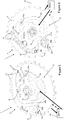
- FIGS. 1-3 schematically illustrate an embodiment of a calendar mechanism 1 according to the invention, in the form of a Muslim calendar.
- FIG. 4 illustrates the operating principle in the form of a diagram.
- the mechanism 1 comprises a mobile of month 3, which comprises a wheel 4 carrying fixed teeth 5 with respect to the wheel 4.
- the number of fixed teeth 5 is chosen according to the number of days maximum to be displayed, in particular thirty in the case illustrated. An integer multiple of this number is also possible.
- the positioning of the mobile of month 3 can be provided in a conventional manner by means of a jumper (not shown).
- Wheel 4 is conventionally associated with one (or more) display member (s) (not shown) which indicates (s) the date.
- the mobile of month 3 is driven by a driving wheel 7, which comprises a first driving member 7a provided with four teeth or driving fingers separated by gaps, the latter being shaped to cooperate with the fixed teeth 5.
- the driving wheel 7 is arranged to be driven itself by a base movement (not shown) at a rate of Quarter turn in 24 hours, typically around midnight.
- the number of teeth or driving fingers can be chosen according to the needs of the watchmaker, and considered generically, if n is the number of teeth or driving fingers, the driving wheel 7 performs 1 / n turns per day.
- the mobile of month 3 also comprises a rocker 9, pivoted on the wheel 4 at a pivot point 9a, which carries retractable teeth 11 located in a plane different from that of the fixed teeth 5 and integral with the rocker 9.
- the rocker 9 and the retractable teeth 11 are in their retracted - inactive - position while they are in their deployed - active - position in the figures 2 and 3 .
- a return spring (not shown) tends to keep the rocker 9 in its inactive position ( figure 1 ).
- the retractable teeth 11 can cooperate with a second drive member 7b that includes the drive wheel 7.
- the retractable teeth 11 are retractable relative to the periphery of the mobile of month 3.
- This second drive member 7b has a shape substantially similar to the first drive member 7a, but is offset angularly by 1/8 of a turn relative to the latter and is located in a plane allowing it to cooperate with the retractable teeth 11.
- retractable teeth 11 are in their active position ( figures 2 and 3 )
- a quarter turn of the driving wheel 7 rotates the wheel of month 3 one step by means of the interaction between the first drive member 7a and the fixed teeth 5, and a further step to means of the interaction between the second drive member 7b and the retractable teeth 11.
- the calendar mechanism 1 operates only in one direction of rotation.
- the calendar mechanism 1 operates in a reversible manner, that is to say that the number of steps made by the mobile of month 3 following a drive in one way or the other (for example following a manual correction of the date in the opposite direction to the direction of rotation usual of the mobile of month 3) remains correct, and the mechanism remains always correctly indexed compared to the date displayed by means of the indicating bodies associated therewith (not illustrated).
- the wheel 4 has a fixed number of teeth 5 which is a multiple of the maximum number of days in a month, the number of retractable teeth can be multiplied by this multiple.
- the position of the rocker 9 is controlled by means of an actuating system 13 as a function of the position of a first cam 15 and a second cam 17.
- the first cam 15 is located between the pivot point 9a of the rocker 9 and the axis of rotation of the mobile 3, and is arranged to pivot relative to the wheel 4.
- the shape of the first cam represents the first cycle of 12 months, and therefore has portions of greater radius 15a representing the odd months of 29 days, and portions of lower radius 15b representing even months of 30 days. Since the number of days of the twelfth month depends on the year, this month is represented by a notch 15c whose operation will appear more clearly later.
- the second cam 17 is located between the pivot point 9a of the rocker 9 and the periphery of the wheel 4, and is also arranged to pivot with respect to the wheel 4.
- the shape of the second cam 17 represents the second cycle 30 years, which determines the number of days of the twelfth month.
- the shape of this cam 17 extends inwards, and comprises parts of upper radius 17a, which represent the twelfth months to 29 days, and portions of lower radius 17b, which represent the twelfth months to 30 days.
- Such cams are often called “programming cams” because their shape determines the number of days indicated in a month, and thus serves to "program” the sequence indicated by mechanism 1.
- the cams 15, 17 are supported and driven in rotation with respect to the wheel 4 by means of an indexing system 19, which is shown diagrammatically on the Figures 1 to 3 , and ensures that the angular position of each cam 15, 17 relative to the wheel 4 is correctly indexed for the date indicated.
- the indexing system 19 is driven by the wheel 4, and drives the two cams 15, 17 by means of a suitable transmission system, such as a gear, Maltese cross, star or all other appropriate system.
- this transmission system can control the two cams 15, 17 individually, or can control the second cam 17 relative to the first cam (@MB: for information, it is this second type of transmission which is currently planned in our construction: the transmission makes the following path: 4-15-17).
- the details of the indexing system are not part of the invention per se, and will not be described in more detail.
- the actuating system 13 comprises a first lever 21 carrying a feeler 21a, the first lever being pivoted on the wheel 4 at a point of pivoting 21b under the effect of a spring (not shown).
- the first lever 21 also carries a stop in the form of a stud 21c arranged to rest against a flank of the rocker 9 to bring it into its active position ( figure 2 ).
- said first lever 21 could also work directly with said flip-flop 9 without the use of a stud.
- the flip-flop 9 could comprise a stud and the first lever 21 might not have one. It is also possible that the rocker 9 and the first lever 21 each have a stud.
- the first probe 21a follows the first cam 15 so that when the first probe 21a is in contact with a portion of lower radius 15b of the latter ( figure 1 ), the pad 21c does not bring the rocker 9 into its active position, and the retractable teeth 11 are in their retracted position, the second drive member 7b can not interact with the retractable teeth 11, and a cycle of 30 days will be displayed.
- the pad 21c brings the flip-flop 9 and the retractable teeth 11 into their active positions. Therefore, the second drive member 7b can interact with the retractable teeth 11, and a cycle of 29 days will be displayed because the wheel 4 will advance two steps at the end of the month.
- the first probe 21a is in the notch 15c, and therefore the pad 21c is moved away from the rocker 9.
- the length the twelfth month is determined not by the first cam 15, but by the second cam 17.
- a second lever 23 is also pivoted on the wheel 4 at a pivot point 23b, and is in kinematic connection with the first lever 21 by means of complementary toothed segments 21d, 23d carried by each lever 21 23.
- the second lever 23 includes a second probe 23a, which is intended to come into contact with the second cam 17, at least during the twelfth month. If the twelfth month is 30 days, the second probe 23a is in contact with a lower radius portion of the second cam 17, and the actuating device 13 adopts the configuration illustrated in FIG. figure 1 , except that the first probe 21a is opposite the notch 15c.
- the second probe 23a is opposite an upper radius portion 17a of the second cam 17, as shown in FIG. figure 3 .
- the first probe 21a being in front of the notch 15c, it can therefore pivot further towards the axis of rotation of the first cam 15 than in the other positions of the first cam 15.
- the second probe 23a is therefore free to contacting, and seating against, the upper spoke portion 17a of the second cam 17, which pivots the second latch 23 in a clockwise direction (relative to the view of the Figures 1 to 3 .
- the transmission lever 24 also comprises two toothed sectors, or even racks, meshing on either side with said toothed gear 25b and with a complementary tooth sector that the second lever 23 comprises.
- any type of kinematic link between the levers 21, 23, 24 and the additional operating wheel 25 are possible, for example pads cooperating with grooves, a belt or the like.
- the mechanism represents a globally binary logic system, which presents the following transfer table: Cam 1 Cam 2 Rocker 9 0 (lower radius) 0 (lower radius) 0 (retracted, 30 days) 0 1 (upper radius) 0 1 (upper radius) 0 1 (active, 29 days) 1 1 1 (active, 29 days) X (notch) 0 0 X 1 1 (active, 29 days)
- cam 1 has the "priority" in this logic, and that it is only when the first probe 21a is in front of the notch 15c that the cam 2 can influence the position of the rocker 9.
- the figure 4 schematically illustrates the operating principle of the mechanism 1 according to the invention.
- the driving wheel 7 drives around the midnight wheel 4 and, where appropriate, the retractable teeth 11. If the retractable teeth 11 are in their active position and are therefore driven by the second drive member 7b, the force exerted on the rocker drives the wheel 4 by an additional step.
- each modification of the angular position of the mobile of month 3 modifies the state of the indexing system, which modifies the position of the first cam 15 and the second cam 17 so that they are correctly indexed with respect to wheel 4 for the displayed date.
- These cams 15, 17 are palpated by the first and second feelers 21a, 23a respectively, which thus determine the position of the rocker 9.
- FIGS. Figures 1 to 8 illustrate a second embodiment of a Muslim calendar mechanism 1 which applies the same principle as that of Figures 1 to 3 .
- These figures illustrate the mechanism 1, seen from both sides, in particular from the upper side ( Fig. 5 and 6 ) and lower ( Fig. 7 and 8 ), and according to perspective views ( Fig. 5 and 7 ) and in plan ( Fig. 6 and 8 ), within a month of 30 days.
- the driving wheel 7 has not been shown, but may be identical to that illustrated in FIGS. Figures 1 to 3 or any other appropriate form.
- This embodiment differs mainly from the first in the positioning of the second cam 17 and the components of the actuating system 13.
- the first lever 21 extends in a curve so that its rack 21d meshes directly with the toothed sector 25b of the additional operating wheel 25. Consequently, the intermediate levers 23 and 24 of the first embodiment have been removed. Nevertheless, it goes without saying that a different kinematic link between the first lever 21 and the additional operating wheel is also possible.
- the second cam 17 is on the opposite side of the wheel 4, so on the other side than that of the first cam 15, and is located centrally, extending outwardly.
- the second probe 23a is a pin integral with the first lever 21, which extends through an opening 4a made in the wheel 4 so as to feel the second cam 17.
- FIGS 9 to 11 illustrate the same principle of operation as described above, but applied to the February treatment of the Gregorian calendar. As this system is more complicated than those described above, some mounting elements (pins, pins, etc.) have not been illustrated. Moreover, the representation is strongly schematic in order to make its operation appear more clearly, and the elements dealing with the jumps of the days 31 and 30 of the month have been represented separately from those dealing with the jump of the day 29 of the month, in different figures.
- the figure 9 illustrates the elements ensuring the jump from 31 th day of the month during the months of 30 days each and February, and jumping the 30 th day of the month at the end of every February. These jumps follow a single cycle of 12 month, and therefore do not apply the principle of superposition cycles of the invention, but are illustrated here in an interest of completeness.
- the wheel 4 of the mobile of month 1 comprises 31 teeth (or alternatively an integer multiple of 31 teeth) which cooperates with a first drive member 7a of the drive wheel 7, and during its standard operation , turn clockwise in the view of the figure 9 at a rate of one round per month.
- a first additional rocker 27 is pivoted on the wheel 4 (its axis having been removed from the figure), and has two teeth arranged similarly to those of the rocker 9 mentioned above and which are positioned in order to be able to interact with a body.
- a second additional latch 29 is also pivoted on the wheel 4 (its axis has also been removed from the figure), and also has two teeth shifted by a step in the direction -amont relative to those of the first additional latch 27, and which are positioned to be able to interact with yet another additional drive member 7d located in yet another plane on the drive wheel.
- These additional flip-flops 27, 29 operate in a manner similar to flip-flop 9, except that they are each controlled by a single cam.
- the drive members are provided in pairs, offset by 180 °.
- the training mobile is a half-turn per day. Other arrangements are also possible, for example 1, 3 or 4 drive members per level.
- the mobile 3 comprises a first additional cam 31, which is followed by a probe 27a of the first additional flip-flop 27 to bring this flip-flop into its active position at the end of the month of 28, 29 or 30 days.
- This additional cam 31 thus has five projections corresponding to the months of less than 31 days.
- a second additional cam 33, integral in rotation with the first additional cam 31, is also followed by a probe 29a of the second additional rocker 28 to bring this rocker into its active position at each February, and for this purpose this cam additional 31 has a corresponding projection in the month of February.
- the indexing system 19 ensures the angular relationship between the additional cams 31, 33 and the wheel 4, ensuring a rotational speed ratio of 11/12 or 13/12 of the additional cams 31, 33 with respect to the wheel 4 , depending on the direction of relative rotation desired between these components.
- any other speed ratio between the wheel 4 and the cam 31 and between the wheel 4 and the cam 33 is conceivable, provided that the teeth of the latches 27 and 29 are positioned adequately when they pass in front of the mobile Training 7.
- the first cam 15, the rocker 9 (whose axis of rotation 9a has not been illustrated), and the components of the actuating system 13 visible on the figure 10 are superimposed on the additional rockers 27, 29 and the additional cams 31, 33 so that the teeth 11 of the rocker 9 can interact with the second drive member 7b of the driving wheel 7.
- the first cam 15 has 48 sectors representing the first cycle of 4 years / 48 months, most of these sectors have the same radius, lower, 15b (months other than February).
- the three parts of larger radius 15a are bumps representing the month of February which are always non-leap and which cause the flip-flop 9 to its operative position in order to skip the 29th of the month, and a notch 15c is that of a year could possibly be leap (and therefore have 29 days) according to the Gregorian calendar (that is to say every year divisible by 4).
- the indexing system ensures that the first cam 15 makes a quarter turn per year relative to the wheel 4.
- this notch delegates the control of the rocker 9 to at least a second cam 17, located on the opposite side of the wheel 4.
- the mechanism comprises not only a second cam 17, but also a second additional cam 18 coaxial to the second. These two cams are palpated in parallel by the second probe 23a.
- the second cam 17 has twenty sectors, three of which have notches, and the second additional cam 18 has five sectors, one of which has a notch. Indeed, the combination of these notches provides the information of if the year in question is divisible by 100 and not by 400.
- the second cam 17 which performs for example a turn in 400 years with respect to the wheel 4, and the second additional cam 18 which performs a turn in 20 years, also with respect to the same wheel.
- the second cam 17 can for example also make a turn in 80 years, and the second additional cam 18 can make a turn in 400 years.
- a single second cam 17 having 400 sectors is indeed very difficult to achieve given the size of such a mechanism, and it is for this reason that we chose to use the logical combination "AND" of two cams 17, 18. This combined cycle of 400 years is the second cycle within the meaning of the invention.
- This system is also fully reversible and maintains its indexing during a correction back through the drive mobile.
- the illustrated embodiment is not limiting, and according to the arrangement, the dimensioning and the nature of the drive means of the cams 17, 18, any other appropriate speed ratio between the latter can be envisaged and is covered by the present invention, provided that the teeth 11 of the flip-flop 9 are positioned adequately during their passage in front of the training mobile 7. The important thing is that, in February, leap years (so when the probe 21a has the possibility of falling into the notch 15c) and when the teeth 11 are close to the mobile 7, the cams 17 and 18 are correctly positioned.
Landscapes
- Physics & Mathematics (AREA)
- General Physics & Mathematics (AREA)
- Astronomy & Astrophysics (AREA)
- Electromechanical Clocks (AREA)
- Transmission Devices (AREA)
Claims (17)
- Kalendermechanismus (1) für eine Uhr, wobei der Kalendermechanismus (1) dafür eingerichtet ist, eine Information anzuzeigen, die eine Periode aufweist, die gemäß mindestens einem ersten Zyklus und einem zweiten Zyklus variiert, der Mechanismus (1) umfassend:- ein Monatsdrehteil (3), das ein Rad (4) umfasst, das eine Anzahl von festen Zähnen (5) aufweist, wobei die Anzahl in Abhängigkeit von der maximalen Periode der anzuzeigenden Information ausgewählt ist,dadurch gekennzeichnet, dass das Drehteil (3) ferner eine Wippe (9) umfasst, die angeordnet ist, sich zwischen einer inaktiven Position und einer aktiven Position zu bewegen und mit mindestens einem einziehbaren Zahn (11) versehen ist;
und dadurch, dass der Mechanismus (1) Folgendes umfasst:- ein Antriebsdrehteil (7) umfassend ein erstes Antriebselement (7a), das dazu angeordnet ist, mit den festen Zähnen (5) zusammenzuwirken, und ein zweites Antriebselement (7b), das bezogen auf das erste Antriebselement (7a) winkelversetzt ist und dazu angeordnet ist, mit dem einziehbaren Zahn (11) zusammenzuwirken, wenn sich die Wippe (9) in ihrer aktiven Position befindet;- einen ersten Nocken (15), der die Variationen der Periode gemäß dem ersten Zyklus repräsentiert;- mindestens einen zweiten Nocken (17), der die Variationen der Periode gemäß dem zweiten Zyklus repräsentiert;- ein Indexierungssystem (19) das mit dem Rad (4), mit dem ersten Nocken (15) und mit dem zweiten Nocken (17) in kinematischer Verbindung steht und dafür eingerichtet ist, jeden der Nocken (15, 17) bezogen auf das Rad (9) in Abhängigkeit von den Zyklen zu indexieren;- ein System zur Betätigung (13) der Wippe (9), das System zur Betätigung (13) umfassend einen ersten Taster (21a), der dazu bestimmt ist, mit dem ersten Nocken (15) in Kontakt zu treten, und einen zweiten Taster (23a), der dazu bestimmt ist, mit dem zweiten Nocken (17) in Kontakt zu treten, wobei die Taster (21a, 23a) miteinander in kinematischer Verbindung stehen und das System zur Betätigung (13) angeordnet ist, die Wippe (9) unter der Steuerung jedes der Nocken (15, 17) aus ihrer inaktiven Position zu ihrer aktiven Position zu bewegen. - Kalendermechanismus (1) nach Anspruch 1, wobei der erste Nocken (15) und der zweite Nocken (17) jeweils koaxial zu dem Rad (4) verlaufen und von diesem getragen werden.
- Kalendermechanismus (1) nach einem der Ansprüche 1 und 2, wobei jeder der Nocken (15, 17) auf derselben Seite des Rads (4) gelegen ist.
- Kalendermechanismus (1) nach einem der Ansprüche 1 und 2, wobei einer der Nocken (15, 17) auf einer ersten Seite des Rads (4) und der andere der Nocken (17, 15) auf einer zweiten Seite des Rads (4) gelegen ist.
- Kalendermechanismus (1) nach Anspruch 4, wobei sich der zweite Taster (23a) durch eine Öffnung (4a) in dem Rad (4) erstreckt.
- Kalendermechanismus (1) nach einem der vorhergehenden Ansprüche, wobei das System zur Betätigung (13) einen ersten Hebel (21) umfasst, der mit dem ersten Taster (21a) versehen ist, wobei der erste Hebel (21) ebenfalls einen Anschlag (21c) umfasst, der dazu bestimmt ist, mit der Wippe (9) in Kontakt zu treten, um sie unter der Steuerung des ersten Nockens (15) in Richtung ihrer aktiven Position zu bewegen.
- Kalendermechanismus (1) nach dem vorhergehenden Anspruch, wobei der zweite Taster (23a) von dem ersten Hebel (21) getragen wird.
- Kalendermechanismus (1) nach Anspruch 6, wobei das System zur Betätigung einen zweiten Hebel (23) umfasst, der mit dem ersten Hebel (21) in kinematischer Verbindung steht, wobei der zweite Hebel (23) den zweiten Taster (23a) trägt.
- Kalendermechanismus (1) nach einem der Ansprüche 6 bis 8, wobei das System zur Betätigung (13) ein zusätzliches Betätigungsdrehteil (25) umfasst, das zumindest mit dem ersten Hebel (21) in kinematischer Verbindung steht und angeordnet ist, die Wippe (9) unter der Steuerung des zweiten Nockens (17) in Richtung ihrer aktiven Position zu bewegen.
- Kalendermechanismus (1) nach Anspruch 9, wobei das zusätzliche Betätigungsdrehteil (25) bezüglich des Rades (4) schwenkbar angeordnet ist und einen zusätzlichen Betätigungsnocken (25a) umfasst, der dazu bestimmt ist, unter der Steuerung des zweiten Nockens (17) gegen die Wippe (9) zu drücken.
- Kalendermechanismus (1) nach einem der vorhergehenden Ansprüche, wobei der erste Nocken (15) eine Form (15, 15b) aufweist, die für die Anzahl von Tagen in einem Monat repräsentativ ist, die gemäß einem ersten Zyklus variiert, und der zweite Nocken (17) eine Form (17a, 17b) aufweist, die für die Anzahl von Tagen in mindestens einem bestimmten Monat repräsentativ ist, die gemäß einem zweiten Zyklus variiert, und wobei der erste Nocken (15) eine Kerbe (15c) umfasst, die für mindestens einen Monat repräsentativ ist, dessen Anzahl von Tagen gemäß dem zweiten Zyklus bestimmt wird.
- Kalendermechanismus (1) nach Anspruch 11, wobei der erste Zyklus zwölf Monate aufweist, wobei die Form des ersten Nockens (15) die Anzahl von Tagen vom ersten bis zum elften Monat repräsentiert, die gemäß dem ersten Zyklus von zwölf Monaten variiert, wobei die Kerbe (15c) dem zwölften Monat entspricht, und wobei der zweite Zyklus dreißig Jahre aufweist, wobei die Form des zweiten Nockens (17) die Anzahl von Tagen des zwölften Monats repräsentiert, die über den zweiten Zyklus von dreißig Jahren variiert.
- Kalendermechanismus (1) nach Anspruch 11, wobei der erste Zyklus vier Jahre aufweist, wobei die Form des ersten Nockens (15) die Anzahl von Februartagen repräsentiert, die gemäß dem ersten Zyklus von vier Jahren variiert, wobei die Kerbe (15c) dem Monat Februar entspricht, der eventuell in einem Schaltjahr liegt, und wobei der zweite Zyklus 400 Jahre aufweist, wobei die Form des mindestens einen zweiten Nockens (17) die Anzahl von Februartagen der Jahre repräsentiert, die durch vier teilbar sind.
- Kalendermechanismus (1) nach Anspruch 13, ferner umfassend eine zusätzlichen zweiten Nocken (18), der über dem zweiten Nocken (17) liegt, wobei die Kombination von dem zweiten Nocken (17) und dem zusätzlichen zweiten Nocken (18) einen Zyklus von 400 Jahren definiert.
- Kalendermechanismus (1) nach Anspruch 14, wobei der zweite Taster (23a) angeordnet ist, den zweiten Nocken (17) und den zusätzlichen zweiten Nocken (18) parallel zu tasten.
- Kalendermechanismus (1) nach einem der vorhergehenden Ansprüche, wobei die Wippe (9) mindestens zwei einziehbare Zähne (11) trägt, die dieselbe Trennung wie zwei benachbarte feste Zähne (5) aufweisen.
- Kalendermechanismus (1) nach einem der vorhergehenden Ansprüche, ferner umfassend eine Vorrichtung zur Anzeige des Wochentags, die vorzugsweise mit dem Antriebsdrehteil (7) in Verbindung steht.
Applications Claiming Priority (2)
| Application Number | Priority Date | Filing Date | Title |
|---|---|---|---|
| CH01656/15A CH711749A1 (fr) | 2015-11-13 | 2015-11-13 | Mécanisme de calendrier pour pièce d'horlogerie. |
| PCT/EP2016/077398 WO2017081231A1 (fr) | 2015-11-13 | 2016-11-11 | Mecanisme de calendrier pour piece d'horlogerie |
Publications (2)
| Publication Number | Publication Date |
|---|---|
| EP3374830A1 EP3374830A1 (de) | 2018-09-19 |
| EP3374830B1 true EP3374830B1 (de) | 2019-08-21 |
Family
ID=54783314
Family Applications (1)
| Application Number | Title | Priority Date | Filing Date |
|---|---|---|---|
| EP16794350.5A Active EP3374830B1 (de) | 2015-11-13 | 2016-11-11 | Kalendermechanismus für eine uhr |
Country Status (7)
| Country | Link |
|---|---|
| US (1) | US11169486B2 (de) |
| EP (1) | EP3374830B1 (de) |
| JP (1) | JP6781254B2 (de) |
| CN (1) | CN108292119B (de) |
| CH (1) | CH711749A1 (de) |
| HK (1) | HK1255859B (de) |
| WO (1) | WO2017081231A1 (de) |
Cited By (1)
| Publication number | Priority date | Publication date | Assignee | Title |
|---|---|---|---|---|
| FR3164801A1 (fr) * | 2024-07-16 | 2026-01-23 | Horlogerie V. Remontet | Mécanisme à Quantième perpétuel coaxial |
Families Citing this family (7)
| Publication number | Priority date | Publication date | Assignee | Title |
|---|---|---|---|---|
| CH714835A1 (de) * | 2018-03-26 | 2019-09-30 | Scarpatetti Mario | Ewiger Kalender für eine mechanische Uhr mit automatischer Korrektur der ungleichlangen Säkularjahre nach gregorianischem Kalender. |
| EP3567438B1 (de) * | 2018-05-09 | 2022-03-23 | Rolex Sa | Kalendersystem für uhr |
| CH715119A1 (fr) * | 2018-06-22 | 2019-12-30 | Montblanc Montre Sa | Mécanisme de quantième perpétuel pour pièce d'horlogerie. |
| IT201900004735A1 (it) * | 2019-03-29 | 2020-09-29 | La Vallee S R L | Dispositivo indicatore per orologeria |
| EP3722890B1 (de) * | 2019-04-10 | 2026-04-15 | ETA SA Manufacture Horlogère Suisse | Vorrichtung zur anzeige einer folge von periodischen ereignissen, die einen jahreszyklus bilden, und eine solche anzeigevorrichtung umfassende uhr |
| CH717492A1 (fr) * | 2020-06-03 | 2021-12-15 | Parmigiani Michel | Calendrier Hégirien. |
| EP4053639B1 (de) * | 2021-03-04 | 2025-01-01 | Rolex Sa | Vorrichtung zur auswahl von uhrfunktionen |
Family Cites Families (27)
| Publication number | Priority date | Publication date | Assignee | Title |
|---|---|---|---|---|
| US368961A (en) * | 1887-08-30 | Calendar-clock | ||
| US30166A (en) * | 1860-09-25 | 1860-09-25 | Calendar-clock | |
| US1755696A (en) * | 1925-02-19 | 1930-04-22 | Kluge Kurt | Perpetual date indicator |
| GB265779A (en) * | 1926-02-16 | 1927-02-17 | Kurt Kluge | Improvements in or relating to perpetual date indicators |
| CH574125B5 (de) * | 1972-04-05 | 1976-03-31 | Suisse Horlogerie | |
| DE2943636A1 (de) * | 1979-10-29 | 1981-05-07 | Paul 7032 Sindelfingen Merkle | Kalenderschaltwerk |
| CH642809B (fr) * | 1980-11-07 | Longines Montres Comp D | Montre avec un mecanisme de quantieme perpetuel. | |
| US4464058A (en) * | 1982-09-29 | 1984-08-07 | Weller Barton L | World time and day indicator clock |
| DE3505733C1 (de) * | 1985-02-20 | 1986-10-23 | IWC International Watch Co AG, Schaffhausen | Uhr |
| CH681674B5 (fr) * | 1991-04-17 | 1993-11-15 | Montres Breguet Sa | Mouvement d'horlogerie à quantième perpétuel. |
| CH684234B5 (fr) * | 1993-01-13 | 1995-02-15 | Michel Parmigiani | Calendrier musulman. |
| CH684815B5 (fr) * | 1993-07-15 | 1995-07-14 | Longines Montres Comp D | Mécanisme de quantième annuel pour pièce d'horlogerie. |
| DE60232054D1 (de) * | 2002-02-11 | 2009-06-04 | Rolex Sa | Jährlicher Kalendermechanismus für Uhrwerk |
| ATE415648T1 (de) * | 2002-04-02 | 2008-12-15 | Nardin Ulysse Sa | Vorrichtung mit programmrad für den mechanismus eines ewigen kalenders sowie uhr mit solchem mechanismus |
| CH697662B1 (fr) * | 2004-04-14 | 2009-01-15 | Chopard Manufacture Sa | Mécanisme de quantième perpétuel ou annuel. |
| DE102005014328B3 (de) * | 2005-03-24 | 2006-07-20 | Lange Uhren Gmbh | Datumschaltung |
| EP1801670B1 (de) * | 2005-12-23 | 2010-08-04 | The Swatch Group Research and Development Ltd. | Mechanismus zur Anzeige von Werten in variablen Zyklen, insbesondere in einem Mond-und Sonnen-Kalender |
| EP1818738A3 (de) * | 2006-02-14 | 2011-05-11 | Franck Müller Watchland SA | Vierhundertjähriger ewiger Kalender |
| JP5181133B2 (ja) * | 2008-11-28 | 2013-04-10 | セイコーインスツル株式会社 | 月車と日車を備えたカレンダ機構付き時計 |
| EP2490084B1 (de) * | 2011-02-17 | 2016-07-20 | Glashütter Uhrenbetrieb GmbH | Datumsmechanismus |
| CH705737B1 (fr) * | 2011-11-11 | 2015-12-31 | Gfpi S A | Mécanisme d'entraînement d'un indicateur d'une information liée à un mouvement horloger. |
| JP6091942B2 (ja) * | 2012-08-01 | 2017-03-08 | セイコーインスツル株式会社 | カレンダ機構並びに該機構を備えたムーブメント及びカレンダ時計 |
| EP3026505B1 (de) * | 2014-11-27 | 2017-09-27 | Société anonyme de la Manufacture d'Horlogerie Audemars Piguet & Cie | Uhrmechanismus eines Jahres- oder ewigen Kalenders, und Uhr, die eine solche Anwendung umfasst |
| EP3026504B1 (de) * | 2014-11-27 | 2017-09-27 | Société anonyme de la Manufacture d'Horlogerie Audemars Piguet & Cie | Uhrmechanismus eines Jahres- oder ewigen Kalenders, und Uhr, die eine solche Anwendung umfasst |
| EP3640747B1 (de) * | 2016-07-15 | 2025-09-10 | Montres Breguet S.A. | Zeitgleichungsmechanismus, der durch eine differenzialvorrichtung gesteuert wird |
| EP3495895B1 (de) * | 2017-12-11 | 2022-02-23 | Omega SA | Akustischer anzeigemechanismus für uhr, insbesondere chronographen-repetition |
| CH715809B1 (fr) * | 2019-02-01 | 2025-01-31 | Mft Dhorlogerie Audemars Piguet Sa | Pièce d'horlogerie comportant un affichage à pas variable. |
-
2015
- 2015-11-13 CH CH01656/15A patent/CH711749A1/fr not_active Application Discontinuation
-
2016
- 2016-11-11 US US15/774,870 patent/US11169486B2/en active Active
- 2016-11-11 CN CN201680069482.3A patent/CN108292119B/zh active Active
- 2016-11-11 WO PCT/EP2016/077398 patent/WO2017081231A1/fr not_active Ceased
- 2016-11-11 HK HK18114935.9A patent/HK1255859B/zh unknown
- 2016-11-11 JP JP2018523510A patent/JP6781254B2/ja active Active
- 2016-11-11 EP EP16794350.5A patent/EP3374830B1/de active Active
Non-Patent Citations (1)
| Title |
|---|
| None * |
Cited By (1)
| Publication number | Priority date | Publication date | Assignee | Title |
|---|---|---|---|---|
| FR3164801A1 (fr) * | 2024-07-16 | 2026-01-23 | Horlogerie V. Remontet | Mécanisme à Quantième perpétuel coaxial |
Also Published As
| Publication number | Publication date |
|---|---|
| CN108292119B (zh) | 2020-06-12 |
| JP6781254B2 (ja) | 2020-11-04 |
| US20180335755A1 (en) | 2018-11-22 |
| CN108292119A (zh) | 2018-07-17 |
| EP3374830A1 (de) | 2018-09-19 |
| HK1255859B (zh) | 2020-04-29 |
| US11169486B2 (en) | 2021-11-09 |
| JP2018533733A (ja) | 2018-11-15 |
| WO2017081231A1 (fr) | 2017-05-18 |
| CH711749A1 (fr) | 2017-05-15 |
Similar Documents
| Publication | Publication Date | Title |
|---|---|---|
| EP3374830B1 (de) | Kalendermechanismus für eine uhr | |
| EP1785783B1 (de) | Jahreskalendermechanismus für Uhrwerk | |
| EP2490084B1 (de) | Datumsmechanismus | |
| EP2329325B1 (de) | Anzeigemechanismus für Uhr, der die Anzeige sowie das Ausblenden der aktuellen Uhrzeit ermöglicht | |
| EP3008523B1 (de) | Kalendermechanismus für ein uhrwerk | |
| EP1962152B1 (de) | Schutzvorrichtung für Anzeige. | |
| EP3629102B1 (de) | Anzeigemechanismus mit einer fensteranzeige | |
| EP2720090B1 (de) | Universaluhr | |
| EP3904964A1 (de) | Anzeigevorrichtung einer uhrzeitanzeige oder eines abgeleiteten uhrzeitwerts und indexierungsvorrichtung | |
| WO2014177290A1 (fr) | Piece d'horlogerie comprenant un dispositif d'affichage de quantieme | |
| WO2010026216A1 (fr) | Mecanisme d'affichage d'une information periodique | |
| EP3460588B1 (de) | Datumsmechanismus | |
| EP2811348A2 (de) | Uhrmechanismus zur Speicherung und Anzeige einer Zeitanzeige | |
| EP1734419B1 (de) | Uhr mit Kalendermechanismus | |
| EP3904962B1 (de) | Indexierungsvorrichtung und anzeigevorrichtung einer uhrzeitanzeige oder eines abgeleiteten uhrzeitwerts | |
| CH717502A1 (fr) | Système de calendrier pour pièce d'horlogerie. | |
| CH717422A2 (fr) | Mécanisme de quantième. | |
| EP3159752B1 (de) | Mobiles programmiergerät für uhrwerk | |
| EP4407384A1 (de) | Sicherheitsmodul für einen ewigen kalendermechanismus einer uhrwerke | |
| CH699102B1 (fr) | Mobile d'entraînement bidirectionnel, pièce d'horlogerie le comportant et mécanisme indicateur de quantième ou de mois. | |
| CH718804B1 (fr) | Mécanisme de quantième perpétuel ou annuel. | |
| EP4730050A1 (de) | Uhrvorrichtung zur anzeige einer uhrinformation und betriebsverfahren dafür | |
| CH719086A1 (fr) | Pièce d'horlogerie comprenant un mécanisme de quantième et un mécanisme de correction de la date ou des mois. | |
| CH719613B1 (fr) | Mobile de commande pour dispositif d'affichage horloger, dispositif d'affichage et mouvement horloger correspondants. | |
| CH715152A1 (fr) | Mécanisme d'affichage du quantième de type grande date. |
Legal Events
| Date | Code | Title | Description |
|---|---|---|---|
| STAA | Information on the status of an ep patent application or granted ep patent |
Free format text: STATUS: UNKNOWN |
|
| STAA | Information on the status of an ep patent application or granted ep patent |
Free format text: STATUS: THE INTERNATIONAL PUBLICATION HAS BEEN MADE |
|
| PUAI | Public reference made under article 153(3) epc to a published international application that has entered the european phase |
Free format text: ORIGINAL CODE: 0009012 |
|
| STAA | Information on the status of an ep patent application or granted ep patent |
Free format text: STATUS: REQUEST FOR EXAMINATION WAS MADE |
|
| 17P | Request for examination filed |
Effective date: 20180612 |
|
| AK | Designated contracting states |
Kind code of ref document: A1 Designated state(s): AL AT BE BG CH CY CZ DE DK EE ES FI FR GB GR HR HU IE IS IT LI LT LU LV MC MK MT NL NO PL PT RO RS SE SI SK SM TR |
|
| AX | Request for extension of the european patent |
Extension state: BA ME |
|
| DAV | Request for validation of the european patent (deleted) | ||
| DAX | Request for extension of the european patent (deleted) | ||
| GRAP | Despatch of communication of intention to grant a patent |
Free format text: ORIGINAL CODE: EPIDOSNIGR1 |
|
| STAA | Information on the status of an ep patent application or granted ep patent |
Free format text: STATUS: GRANT OF PATENT IS INTENDED |
|
| INTG | Intention to grant announced |
Effective date: 20190326 |
|
| GRAS | Grant fee paid |
Free format text: ORIGINAL CODE: EPIDOSNIGR3 |
|
| GRAA | (expected) grant |
Free format text: ORIGINAL CODE: 0009210 |
|
| STAA | Information on the status of an ep patent application or granted ep patent |
Free format text: STATUS: THE PATENT HAS BEEN GRANTED |
|
| AK | Designated contracting states |
Kind code of ref document: B1 Designated state(s): AL AT BE BG CH CY CZ DE DK EE ES FI FR GB GR HR HU IE IS IT LI LT LU LV MC MK MT NL NO PL PT RO RS SE SI SK SM TR |
|
| REG | Reference to a national code |
Ref country code: GB Ref legal event code: FG4D Free format text: NOT ENGLISH |
|
| REG | Reference to a national code |
Ref country code: HK Ref legal event code: DE Ref document number: 1255859 Country of ref document: HK Ref country code: CH Ref legal event code: EP |
|
| REG | Reference to a national code |
Ref country code: DE Ref legal event code: R096 Ref document number: 602016019150 Country of ref document: DE |
|
| REG | Reference to a national code |
Ref country code: AT Ref legal event code: REF Ref document number: 1170448 Country of ref document: AT Kind code of ref document: T Effective date: 20190915 |
|
| REG | Reference to a national code |
Ref country code: IE Ref legal event code: FG4D Free format text: LANGUAGE OF EP DOCUMENT: FRENCH |
|
| REG | Reference to a national code |
Ref country code: CH Ref legal event code: NV Representative=s name: E-PATENT S.A., CH |
|
| REG | Reference to a national code |
Ref country code: LT Ref legal event code: MG4D |
|
| REG | Reference to a national code |
Ref country code: NL Ref legal event code: MP Effective date: 20190821 |
|
| PG25 | Lapsed in a contracting state [announced via postgrant information from national office to epo] |
Ref country code: NL Free format text: LAPSE BECAUSE OF FAILURE TO SUBMIT A TRANSLATION OF THE DESCRIPTION OR TO PAY THE FEE WITHIN THE PRESCRIBED TIME-LIMIT Effective date: 20190821 Ref country code: SE Free format text: LAPSE BECAUSE OF FAILURE TO SUBMIT A TRANSLATION OF THE DESCRIPTION OR TO PAY THE FEE WITHIN THE PRESCRIBED TIME-LIMIT Effective date: 20190821 Ref country code: BG Free format text: LAPSE BECAUSE OF FAILURE TO SUBMIT A TRANSLATION OF THE DESCRIPTION OR TO PAY THE FEE WITHIN THE PRESCRIBED TIME-LIMIT Effective date: 20191121 Ref country code: LT Free format text: LAPSE BECAUSE OF FAILURE TO SUBMIT A TRANSLATION OF THE DESCRIPTION OR TO PAY THE FEE WITHIN THE PRESCRIBED TIME-LIMIT Effective date: 20190821 Ref country code: PT Free format text: LAPSE BECAUSE OF FAILURE TO SUBMIT A TRANSLATION OF THE DESCRIPTION OR TO PAY THE FEE WITHIN THE PRESCRIBED TIME-LIMIT Effective date: 20191223 Ref country code: HR Free format text: LAPSE BECAUSE OF FAILURE TO SUBMIT A TRANSLATION OF THE DESCRIPTION OR TO PAY THE FEE WITHIN THE PRESCRIBED TIME-LIMIT Effective date: 20190821 Ref country code: FI Free format text: LAPSE BECAUSE OF FAILURE TO SUBMIT A TRANSLATION OF THE DESCRIPTION OR TO PAY THE FEE WITHIN THE PRESCRIBED TIME-LIMIT Effective date: 20190821 Ref country code: NO Free format text: LAPSE BECAUSE OF FAILURE TO SUBMIT A TRANSLATION OF THE DESCRIPTION OR TO PAY THE FEE WITHIN THE PRESCRIBED TIME-LIMIT Effective date: 20191121 |
|
| PG25 | Lapsed in a contracting state [announced via postgrant information from national office to epo] |
Ref country code: IS Free format text: LAPSE BECAUSE OF FAILURE TO SUBMIT A TRANSLATION OF THE DESCRIPTION OR TO PAY THE FEE WITHIN THE PRESCRIBED TIME-LIMIT Effective date: 20191221 Ref country code: LV Free format text: LAPSE BECAUSE OF FAILURE TO SUBMIT A TRANSLATION OF THE DESCRIPTION OR TO PAY THE FEE WITHIN THE PRESCRIBED TIME-LIMIT Effective date: 20190821 Ref country code: ES Free format text: LAPSE BECAUSE OF FAILURE TO SUBMIT A TRANSLATION OF THE DESCRIPTION OR TO PAY THE FEE WITHIN THE PRESCRIBED TIME-LIMIT Effective date: 20190821 Ref country code: AL Free format text: LAPSE BECAUSE OF FAILURE TO SUBMIT A TRANSLATION OF THE DESCRIPTION OR TO PAY THE FEE WITHIN THE PRESCRIBED TIME-LIMIT Effective date: 20190821 Ref country code: RS Free format text: LAPSE BECAUSE OF FAILURE TO SUBMIT A TRANSLATION OF THE DESCRIPTION OR TO PAY THE FEE WITHIN THE PRESCRIBED TIME-LIMIT Effective date: 20190821 Ref country code: GR Free format text: LAPSE BECAUSE OF FAILURE TO SUBMIT A TRANSLATION OF THE DESCRIPTION OR TO PAY THE FEE WITHIN THE PRESCRIBED TIME-LIMIT Effective date: 20191122 |
|
| REG | Reference to a national code |
Ref country code: AT Ref legal event code: MK05 Ref document number: 1170448 Country of ref document: AT Kind code of ref document: T Effective date: 20190821 |
|
| PG25 | Lapsed in a contracting state [announced via postgrant information from national office to epo] |
Ref country code: TR Free format text: LAPSE BECAUSE OF FAILURE TO SUBMIT A TRANSLATION OF THE DESCRIPTION OR TO PAY THE FEE WITHIN THE PRESCRIBED TIME-LIMIT Effective date: 20190821 |
|
| PG25 | Lapsed in a contracting state [announced via postgrant information from national office to epo] |
Ref country code: AT Free format text: LAPSE BECAUSE OF FAILURE TO SUBMIT A TRANSLATION OF THE DESCRIPTION OR TO PAY THE FEE WITHIN THE PRESCRIBED TIME-LIMIT Effective date: 20190821 Ref country code: PL Free format text: LAPSE BECAUSE OF FAILURE TO SUBMIT A TRANSLATION OF THE DESCRIPTION OR TO PAY THE FEE WITHIN THE PRESCRIBED TIME-LIMIT Effective date: 20190821 Ref country code: RO Free format text: LAPSE BECAUSE OF FAILURE TO SUBMIT A TRANSLATION OF THE DESCRIPTION OR TO PAY THE FEE WITHIN THE PRESCRIBED TIME-LIMIT Effective date: 20190821 Ref country code: IT Free format text: LAPSE BECAUSE OF FAILURE TO SUBMIT A TRANSLATION OF THE DESCRIPTION OR TO PAY THE FEE WITHIN THE PRESCRIBED TIME-LIMIT Effective date: 20190821 Ref country code: EE Free format text: LAPSE BECAUSE OF FAILURE TO SUBMIT A TRANSLATION OF THE DESCRIPTION OR TO PAY THE FEE WITHIN THE PRESCRIBED TIME-LIMIT Effective date: 20190821 Ref country code: DK Free format text: LAPSE BECAUSE OF FAILURE TO SUBMIT A TRANSLATION OF THE DESCRIPTION OR TO PAY THE FEE WITHIN THE PRESCRIBED TIME-LIMIT Effective date: 20190821 |
|
| PG25 | Lapsed in a contracting state [announced via postgrant information from national office to epo] |
Ref country code: SM Free format text: LAPSE BECAUSE OF FAILURE TO SUBMIT A TRANSLATION OF THE DESCRIPTION OR TO PAY THE FEE WITHIN THE PRESCRIBED TIME-LIMIT Effective date: 20190821 Ref country code: CZ Free format text: LAPSE BECAUSE OF FAILURE TO SUBMIT A TRANSLATION OF THE DESCRIPTION OR TO PAY THE FEE WITHIN THE PRESCRIBED TIME-LIMIT Effective date: 20190821 Ref country code: SK Free format text: LAPSE BECAUSE OF FAILURE TO SUBMIT A TRANSLATION OF THE DESCRIPTION OR TO PAY THE FEE WITHIN THE PRESCRIBED TIME-LIMIT Effective date: 20190821 Ref country code: IS Free format text: LAPSE BECAUSE OF FAILURE TO SUBMIT A TRANSLATION OF THE DESCRIPTION OR TO PAY THE FEE WITHIN THE PRESCRIBED TIME-LIMIT Effective date: 20200224 |
|
| REG | Reference to a national code |
Ref country code: DE Ref legal event code: R097 Ref document number: 602016019150 Country of ref document: DE |
|
| PLBE | No opposition filed within time limit |
Free format text: ORIGINAL CODE: 0009261 |
|
| STAA | Information on the status of an ep patent application or granted ep patent |
Free format text: STATUS: NO OPPOSITION FILED WITHIN TIME LIMIT |
|
| PG2D | Information on lapse in contracting state deleted |
Ref country code: IS |
|
| PG25 | Lapsed in a contracting state [announced via postgrant information from national office to epo] |
Ref country code: LU Free format text: LAPSE BECAUSE OF NON-PAYMENT OF DUE FEES Effective date: 20191111 Ref country code: MC Free format text: LAPSE BECAUSE OF FAILURE TO SUBMIT A TRANSLATION OF THE DESCRIPTION OR TO PAY THE FEE WITHIN THE PRESCRIBED TIME-LIMIT Effective date: 20190821 |
|
| 26N | No opposition filed |
Effective date: 20200603 |
|
| REG | Reference to a national code |
Ref country code: BE Ref legal event code: MM Effective date: 20191130 |
|
| PG25 | Lapsed in a contracting state [announced via postgrant information from national office to epo] |
Ref country code: SI Free format text: LAPSE BECAUSE OF FAILURE TO SUBMIT A TRANSLATION OF THE DESCRIPTION OR TO PAY THE FEE WITHIN THE PRESCRIBED TIME-LIMIT Effective date: 20190821 |
|
| PG25 | Lapsed in a contracting state [announced via postgrant information from national office to epo] |
Ref country code: IE Free format text: LAPSE BECAUSE OF NON-PAYMENT OF DUE FEES Effective date: 20191111 |
|
| PG25 | Lapsed in a contracting state [announced via postgrant information from national office to epo] |
Ref country code: BE Free format text: LAPSE BECAUSE OF NON-PAYMENT OF DUE FEES Effective date: 20191130 |
|
| PG25 | Lapsed in a contracting state [announced via postgrant information from national office to epo] |
Ref country code: CY Free format text: LAPSE BECAUSE OF FAILURE TO SUBMIT A TRANSLATION OF THE DESCRIPTION OR TO PAY THE FEE WITHIN THE PRESCRIBED TIME-LIMIT Effective date: 20190821 |
|
| PG25 | Lapsed in a contracting state [announced via postgrant information from national office to epo] |
Ref country code: MT Free format text: LAPSE BECAUSE OF FAILURE TO SUBMIT A TRANSLATION OF THE DESCRIPTION OR TO PAY THE FEE WITHIN THE PRESCRIBED TIME-LIMIT Effective date: 20190821 Ref country code: HU Free format text: LAPSE BECAUSE OF FAILURE TO SUBMIT A TRANSLATION OF THE DESCRIPTION OR TO PAY THE FEE WITHIN THE PRESCRIBED TIME-LIMIT; INVALID AB INITIO Effective date: 20161111 |
|
| PG25 | Lapsed in a contracting state [announced via postgrant information from national office to epo] |
Ref country code: MK Free format text: LAPSE BECAUSE OF FAILURE TO SUBMIT A TRANSLATION OF THE DESCRIPTION OR TO PAY THE FEE WITHIN THE PRESCRIBED TIME-LIMIT Effective date: 20190821 |
|
| REG | Reference to a national code |
Ref country code: CH Ref legal event code: PK Free format text: RECTIFICATIONS |
|
| REG | Reference to a national code |
Ref country code: DE Ref legal event code: R081 Ref document number: 602016019150 Country of ref document: DE Owner name: GREUBEL FORSEY S.A., CH Free format text: FORMER OWNERS: COMPLITIME SA, LA CHAUX-DE-FONDS, CH; GFPI S.A., LA CHAUX-DE-FONDS, CH Ref country code: DE Ref legal event code: R081 Ref document number: 602016019150 Country of ref document: DE Owner name: CT TIME S.A., CH Free format text: FORMER OWNERS: COMPLITIME SA, LA CHAUX-DE-FONDS, CH; GFPI S.A., LA CHAUX-DE-FONDS, CH |
|
| REG | Reference to a national code |
Ref country code: DE Ref legal event code: R081 Ref document number: 602016019150 Country of ref document: DE Owner name: CT TIME S.A., CH Free format text: FORMER OWNER: GREUBEL FORSEY S.A., LA CHAUX-DE-FONDS, CH |
|
| REG | Reference to a national code |
Ref country code: GB Ref legal event code: 732E Free format text: REGISTERED BETWEEN 20250925 AND 20251001 |
|
| REG | Reference to a national code |
Ref country code: GB Ref legal event code: 732E Free format text: REGISTERED BETWEEN 20251002 AND 20251008 |
|
| REG | Reference to a national code |
Ref country code: CH Ref legal event code: U11 Free format text: ST27 STATUS EVENT CODE: U-0-0-U10-U11 (AS PROVIDED BY THE NATIONAL OFFICE) Effective date: 20251201 |
|
| PGFP | Annual fee paid to national office [announced via postgrant information from national office to epo] |
Ref country code: DE Payment date: 20251128 Year of fee payment: 10 |
|
| PGFP | Annual fee paid to national office [announced via postgrant information from national office to epo] |
Ref country code: GB Payment date: 20251127 Year of fee payment: 10 |
|
| PGFP | Annual fee paid to national office [announced via postgrant information from national office to epo] |
Ref country code: FR Payment date: 20251125 Year of fee payment: 10 |
|
| PGFP | Annual fee paid to national office [announced via postgrant information from national office to epo] |
Ref country code: CH Payment date: 20251201 Year of fee payment: 10 |