EP3159752B1 - Mobiles programmiergerät für uhrwerk - Google Patents
Mobiles programmiergerät für uhrwerk Download PDFInfo
- Publication number
- EP3159752B1 EP3159752B1 EP16192609.2A EP16192609A EP3159752B1 EP 3159752 B1 EP3159752 B1 EP 3159752B1 EP 16192609 A EP16192609 A EP 16192609A EP 3159752 B1 EP3159752 B1 EP 3159752B1
- Authority
- EP
- European Patent Office
- Prior art keywords
- programming
- plate
- mobile
- organ
- toothed sector
- Prior art date
- Legal status (The legal status is an assumption and is not a legal conclusion. Google has not performed a legal analysis and makes no representation as to the accuracy of the status listed.)
- Active
Links
Images


Classifications
-
- G—PHYSICS
- G04—HOROLOGY
- G04B—MECHANICALLY-DRIVEN CLOCKS OR WATCHES; MECHANICAL PARTS OF CLOCKS OR WATCHES IN GENERAL; TIME PIECES USING THE POSITION OF THE SUN, MOON OR STARS
- G04B19/00—Indicating the time by visual means
- G04B19/24—Clocks or watches with date or week-day indicators, i.e. calendar clocks or watches; Clockwork calendars
- G04B19/243—Clocks or watches with date or week-day indicators, i.e. calendar clocks or watches; Clockwork calendars characterised by the shape of the date indicator
- G04B19/247—Clocks or watches with date or week-day indicators, i.e. calendar clocks or watches; Clockwork calendars characterised by the shape of the date indicator disc-shaped
- G04B19/253—Driving or releasing mechanisms
- G04B19/25333—Driving or releasing mechanisms wherein the date indicators are driven or released mechanically by a clockwork movement
- G04B19/25353—Driving or releasing mechanisms wherein the date indicators are driven or released mechanically by a clockwork movement driven or released stepwise by the clockwork movement
- G04B19/2536—Driving or releasing mechanisms wherein the date indicators are driven or released mechanically by a clockwork movement driven or released stepwise by the clockwork movement automatically corrected at the end of months having less than 31 days
Definitions
- a sliding finger additional is arranged to cooperate with the 24-hour wheel at the end of each month of February of 28 days to advance the first board an additional step, in addition to the two steps planned at the end of the month of 29 days.
- a gear train with wheels having truncated teeth to fulfill the role of cams, is provided to control the position of the sliding finger.
- This device is complex because it has a large number of wheels, some of which are stacked on top of each other, in addition to the sliding element, all these components being carried by the program mobile. Even though this invention aims to provide a simpler construction than the known mechanisms of the prior art, in particular by avoiding the need to use springs and latches, it is nonetheless complex to build and to adjust given the many axes necessary to ensure the mounting of different wheels.
- a main object of the present invention is to propose a different approach, and therefore a construction which is also different from those known from the prior art, by proposing a mobile programming structure robust, uncomplicated, and whose operation is simple and relatively flexible.
- the present invention more particularly relates to a programming mobile as defined in independent claim 1.
- the programming mobile according to the present invention can be constructed in such a way that it can transmit a predetermined number of steps for each complete revolution of its first board, from an actuating member of a watch movement towards a mechanism to be actuated, while the first and second sectors toothed can transmit up to a number n of additional steps each turn, this number of additional steps can be preferably programmed to take a different value each turn of the mobile.
- the first board has its inactive space opposite the actuating member.
- the first toothed sector has its teeth facing the actuating member.
- the first toothed sector is in its abutment position and it drives the first board a step when it is itself driven by the actuating member, or it has been programmed beforehand to be driven until The first board is driven without causing the first board to be driven until the first tooth sector is returned to its abutment position.
- the watchmaking mechanism will have been driven up to n additional steps when the first board has finalized its turn.
- the mobile programming according to the present invention can advantageously be programmed either manually by a user, or automatically by a specific clock mechanism.
- the first and second tooth sectors can be directly integral with each other. They can thus have a common axis of rotation to further simplify the assembly of the mobile programming according to the invention.
- the inactive space of the toothing of the second plank corresponds to at least three steps, in particular when the actuated clock mechanism is engaged with the programming wheel by means of a toothed wheel. possibly with a retrograde movement.
- the assembly comprising the first tooth sector and the second toothed sector has a portion arranged in abutment against a blocking surface secured to the first board or the second board in the abutment position of the first sector. toothed.
- This abutment portion can be made directly as a part of one of the toothed sectors or, alternatively or additionally, a specific component can be provided, integral with one of the toothed sectors, to fulfill the stop function cooperating with at least one of the boards.
- the size of the mobile programming device according to the present invention can be significantly limited.
- the programming mobile may comprise a pawl, integral in rotation with one of the first and second boards and arranged to cooperate with one of the first and second tooth sectors to define the n + 1 angular positions of the first toothed sector.
- the mobile according to the invention may advantageously comprise an actuating surface integral with one of the first and second tooth sectors, intended to be actuated by a programming member of the watch movement to position the first and second sectors. teeth in one of their n + 1 angular positions with reference to the first and second boards, and a release surface integral with one of the first and second boards and intended to allow the triggering of the programming member to a predefined opportune moment.
- the triggering surface may incidentally allow locking of the first and second boards when the actuating surface is actuated.
- the triggering surface is formed in an additional board integral in rotation of the first and second boards.
- the invention also relates to a clock-making mechanism comprising a programming mobile according to the features described above, the mechanism advantageously comprising a programming member arranged to act, periodically or on demand, on at least one of the first and second toothed sectors for positioning the first toothed sector in one of the n + 1 angular positions with reference to the first and second planks during a programming operation.
- the mechanism may comprise a release member integral with the programming member and arranged to cooperate with the triggering surface and trigger the action of the programming member on the actuating surface.
- the programming and triggering members may advantageously be provided on a rocker whose amplitude of rotation can be controlled by the cooperation between a probe and a programming cam during the programming operation at each complete revolution of the first board.
- the rocker it is also possible for the rocker to carry a first surface intended to be actuated by a driving member of the clockwork movement in order to pivot the rocker in the direction of rotation opposite to that in which it turns when of the implementation of the programming operation, and a second surface defining the actuating member intended to act on the toothing of the first board and / or on the first toothed sector when the lever pivots in this direction opposite rotation.
- the first and second surfaces can in particular take the form of fingers and / or beaks.
- the present invention also relates to a watch movement comprising such a programming mechanism and a timepiece comprising such a watch movement.
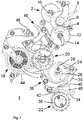
- the figure 1 represents a simplified front view of a part of a watch movement 1 comprising a programming mechanism comprising a programming mobile according to a preferred embodiment of the present invention.
- the watch movement 1 here comprises, by way of non-limiting example, a display mechanism of information relating to a calendar, preferably of yearly or perpetual type.
- the watch movement 1 conventionally comprises a time base and a source of energy not shown.
- a gear train 2 transmits a driving torque from the source of mechanical energy to a roadway 4 and an hour wheel 6 to display the current time by means of hands 8 and 10.
- the hour wheel 6 is arranged in engagement with a 24-hour wheel 12 performing a turn on itself in 24 hours.
- the 24-hour wheel carries a finger 14 for driving the calendar mechanism intended to cooperate with a rocker 16.
- the flip-flop 16 is in turn arranged to drive in rotation a mobile display of the date 18, retrograde type here by way of non-limiting example, via a programming mobile 20 as will emerge from the description which follows.
- the programming mobile 20 is arranged, at the same time, to drive in rotation a display mobile of the months 22.
- the programming mobile 20 is arranged in engagement with a wheel of the months 24 in such a way that this last performs a complete turn on itself in one month, regardless of the duration of the month.
- the wheel of the months 24 carries a spiral cam 26 with which cooperates a probe 28 of a flip-flop of months 30. Once a month, the probe 28 falls from the point of the cam 26 of greater radius on the point of smaller radius, rotating the latch 30 months in the direction of rotation anti-clockwise. In this movement, a spout (not visible) of the latch 30 months acts on the mobile display month 22 to advance one step in the direction of clockwise rotation.
- the display mobile of months 22 can advantageously carry a display member of the month, as illustrated on the figure 1 for example with a display hand of the month 34.
- the mobile display month 22 also carries a cam of months 36 having the general shape of a disc on the periphery of which are formed notches, associated with certain months of the year and whose depth is a function of the number of days of the corresponding month.
- the regions of the cam of the months 36 located at its periphery are associated here in February of leap years, that is to say, counting 29 days, while notches having a first intermediate level of depth are associated with the 30-day months and maximum depth notches are associated with the 31-day months.
- a programming flip-flop 38 is intended to be pivotally mounted on a frame element of the watch movement, close to the wheel of the months 24.
- the programming flip-flop 38 comprises a first probe 40 arranged to cooperate with the periphery of the cam of the months 36 when the latch 38 pivots in the clockwise direction of rotation.
- the latch 38 comprises a second probe 42 intended to cooperate with the additional mobile not shown at the end of the month of 28 days, as will be explained below.
- the flip-flop 38 is arranged to cooperate with the flip-flop 16 and implement a programming operation of the programming mobile 20, in a manner to be described below, so that the date display mobile 18 can to be actuated a variable number of times each complete revolution of the mobile programming 20, depending on the number of days of the corresponding month.
- jumpers 44, 46 or a safety lever 48 are illustrated in FIG. figure 1 but will not be described anymore in detail to the extent that they play only a secondary role in the implementation of the present invention.
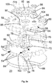
- the mobile is illustrated in exploded perspective with two opposite respective angles of view on the Figures 2a and 2b and it is illustrated assembled on the Figure 2c .
- the programming wheel 20 comprises a first toothed board 50 whose toothing has an inactive space 52 corresponding to a pitch of the toothing. It is also apparent from figure 2a that four teeth 54, on either side of the inactive space 52, have a reduced height relative to the height of the other teeth of the first board.
- the programming wheel 20 also comprises a second toothed board 56 whose toothing has an inactive space 58, corresponding to three steps of the toothing. It is particularly apparent from the figure 2b that four teeth 60, one side of the inactive space 58, and two teeth 62, on the other side of the inactive space 58, have a reduced height relative to the height of the other teeth of the second board .
- An additional plate 64 is also provided, the latter having a general disc shape in which is provided a trigger slot 66, slightly curved and opening to the periphery of the disc.
- first and second toothed sectors 68 and 70 are interposed between the first and second planks 50 and 56.
- Each of the toothed sectors 68, 70 comprises a toothing of five teeth here and is housed in an adapted recess 72, 74 of the one of the boards 50, 56 so that it does not exceed the corresponding board in the direction of the thickness.
- the two toothed sectors 68, 70 are held integral in rotation by means of a pin 76 secured to one of the sectors, being driven away, or possibly glued or welded, into a hole adapted from this sector, and arranged through a hole adapted from the other sector, preferably being adjusted thereto.
- Each toothed sector 68, 70 carries an additional pin 82, 84 extending through a suitable slot 86, 88 of the second plank 56.
- the pin 76 further extends through a curved slot 90 of the second board 56 and a hole in a toothed ring 92 carried by the second board 56 and pivoted on the central shaft 78, such that the toothed ring 92 is made integral in rotation with the two toothed sectors 68 and 70.
- the second plate 56 also carries a pawl 94 held in abutment against the toothing of the toothed ring 92 by a spring 96, to define discrete angular positions of the toothed sectors 68, 70 with reference to the first and second planks 50, 56.
- pawl 94 and the spring 96 are secured to the second board 56 by screws 98 and 100.
- first toothed sector 68 is in a first abutment position in the configuration illustrated in FIG. Figure 2c which corresponds to that which is also illustrated on the figure 2a .
- this abutment position the side of an end tooth of the first toothed sector 68 is positioned in abutment against an abutment surface 102 of the first plank 50.
- the first toothed sector 68 can not rotate in the anti-clockwise rotation direction than by driving the first board 50 with him.
- the first toothed sector 68 can be rotated in the clockwise direction in the view of the Figure 2c to take up to four other angular positions with reference to the first board 50, these positions being marked by the cooperation of the pawl 94 with the toothing of the toothed ring 92.
- the pawl 94 should preferably be removed from the ring 92 to allow the ring to rotate in the clockwise direction on the view of the Figure 2c . This operation may for example be performed by the exercise of pressure on the tail 104 secured to the pawl 94 to lift the latter.
- an additional abutment surface (not visible) in the recess 72 can be provided to define a maximum pivoting amplitude of the first tooth sector 68.
- the first toothed sector 68 can thus take five different angular positions with reference to the first plate 50, as part of a programming operation of the programming mobile 20.
- the first toothed sector 68 can be rotated four times, in the anti-clockwise direction in the view of the Figure 2c , before being thrown again on the other side, as illustrated on the Figure 2c .
- These rotations in the anti-clockwise direction are freely made with reference to the first board 50, that is to say without the latter being driven with the first gear sector 68.
- an action on its tooth located opposite the inactive space 52 to rotate it in the counterclockwise direction necessarily causes a simultaneous rotation of the first board 50, by action on the abutment surface 102.
- the second toothed sector 70 integral in rotation with the first tooth sector 68, exhibits simultaneous similar movements. Indeed, the second toothed sector 70 is, in the position illustrated on the Figure 2c , in abutment against a first abutment surface 106 (visible on the figure 2b ), optional, formed in the recess 74 of the second plate 56. If the first toothed sector 68 is driven to move to its opposite stop, the second toothed sector 70 does the same, to be in abutment against a second abutment surface 108 (visible on the figure 2b ), optional, formed in the recess 74 of the second plate 56.
- the second toothed sector 70 presents a single tooth facing the inactive space 58 of the second board 56, its four other teeth being retracted under the four teeth 60 of reduced height.
- the first toothed sector 68 pivots to its second stop position, the second toothed sector 70 presents three of its teeth opposite the inactive space 58, its two other teeth then being retracted under the two teeth 62 of reduced height. .
- first toothed sector 68 When the first toothed sector 68 is in its first abutment position as illustrated in FIG. Figure 2c its tooth located next to the inactive space 52 of the first board 50 fulfills the same role as would play the missing tooth of the first board, to ensure a rotation of one step of the entire mobile programming 20.
- the second toothed sector 70 reserves an inactive sector corresponding to two steps to allow a return to zero of the retrograde date display mobile 18.
- first toothed sector 68 is pivoted by one step in the clockwise direction, with reference to the stop position illustrated in FIG. Figure 2c its second tooth is then located opposite the inactive space 52 and the rocker 16 can act on the latter to rotate the first toothed sector 68, in the anti-clockwise direction, without causing the first board 50.
- second toothed sector 70 then drives the display mobile of the date 18 by one additional step.
- the first toothed sector 68 has resumed its stop position of the Figure 2c and, in the next turn of the 24-hour wheel, when the latch 16 acts on the first tooth of the first toothed sector 68, to cause the latter to rotate in the counterclockwise direction, the first plank 50 is also driven by a not to start a ride again.
- the display mobile of the date 18 resets to zero since no tooth no longer ensures its locking.
- the programming mobile 20 is arranged in such a way that it allows, at the base, to drive the display mobile 18 of 26 steps each turn (from the 1st to the 27th of the month in course). Then, it can be programmed to train it for 1 additional step for the purposes of 28 days, 2 steps for the month ends of 29 days, 3 steps for the ends of 30 days and 4 days. not during 31-day month ends.
- the programming mobile cooperates with another mechanism that would not necessarily be retrograde and, in this case, it could be expected that the mobile programming is programmable to give rise to no additional step when certain turns, without departing from the scope of the present invention.
- the inactive space 58 of the second board 56 could thus correspond to only one step instead of three.
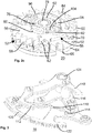
- the figure 3 represents a simplified perspective view of the flip-flop 16 and in particular makes it possible to better understand how it cooperates with the programming mobile 20.
- the latch 16 here has substantially three different levels.
- the rocker 16 has on its first level a first input member having the shape of a finger 110 to be actuated by the drive finger 14 of the 24-hour wheel to rotate the entire scale 16
- the latter is intended to fulfill the role of programming unit in relation to the programming mobile 20.
- it comprises an actuating finger 112 intended to cooperate with the programming mobile 20, to program the number of additional steps to implement at each complete turn to take into account the number of days of the corresponding month.
- the rocker 16 comprises an actuating nose 114 arranged to retransmit the programming mobile operations that the rocker 16 undergoes the finger 14 of the wheel 24 hours, once every 24 hours.
- the actuating spout 114 is pivotally mounted on an arm 116 of the rocker 16 while being held in its default position by a straight spring 118 in a conventional manner.
- the rocker 16 comprises a trigger member, having the shape of a slightly curved arm 120 and intended to be inserted periodically into the trigger slot 66 of the programming mobile 20, during the programming operations .
- the rocker comprises, in a third level, a second input member in the form of a toothed rake 122, by which information relating to the number of additional steps to be programmed each month is transmitted to the flip-flop 16, in charge. to retransmit to the programming mobile 20.
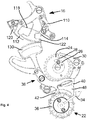
- the figure 4 represents a simplified front view illustrating the cooperation of the flip-flop 16 with the programming flip-flop 38 and making it possible to understand how the flip-flop 16 acts on the programming mobile to program it with a number of additional steps corresponding to the number of days starting from 28 each month.
- the programming rocker 38 comprises a rake 130 arranged in permanent engagement with the rake 122 of the rocker 16.
- the trigger slot 66 of the additional board 64 is positioned opposite the trigger arm 120 of the rocker 16, the latter being maintained in support against the periphery of the additional board 64 the rest of the time by an elastic member not shown.
- This elastic member can indifferently be arranged to act directly on the flip-flop 16 or on the programming flip-flop 38.
- the arm 120 then enters the trigger slot 66 to actuate the programming operation of the programming mobile 20. Note that, at the same time, the arm 120 performs a locking function by preventing any rotation of the board additional 64, as well as first and second boards 50 and 56 connected thereto.
- the first and second probes 40 and 42 of the programming flip-flop 38 descend in the direction respectively of the cam of the months 36 and the additional mobile of the non-leap years (not shown).
- a region of the cam months of maximum radius is positioned next to the probe 40 which is placed in support against it.
- a notch of the cam months of intermediate radius is positioned next to the probe 40 which is placed in support against it.
- a notch of the cam months of minimum radius is positioned next to the probe 40 which is placed in support against it.
- the additional mobile non-leap years fulfills the role of a stop for the probe 42 which stops the stroke of the programming lever 38 before the probe 40 could come into contact with the cam months 36.
- the flip-flop 16 is extracted from the trigger slot 66 instants before the next step of 26.
- the finger 110 is on the passage of the drive finger 14 less than 24 hours after the step of mobile programming 20 which led the latch 16 to lock the latter.
- the trigger member 120 is thus extracted, by action of the drive finger 14 on the finger 110, this action continuing after the extraction of the trigger member 120 to proceed to the transition from 25 to 26 of the current month .
- the figure 5 illustrates how the flip-flop 16 retransmits to the programming mobile 20 the rotation it undergoes the programming flip-flop 38 during programming operations.
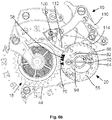
- FIGS. 6a to 6e illustrate the chronological behavior of the mechanism just described during the last days of a 30-day month.
- the programming mobile 20 was programmed on the 25th, as described above.
- the illustrated month comprising 30 days
- the first toothed sector 68 was shifted three steps to a maximum of four compared to the boards 50 and 56, to move the display mobile of the date 18 from 27 to 28, from 28 to 29 and 29 to 30.
- the second toothed sector 70 is therefore shifted by the same number of steps. This number of steps is visible by reading the position of the ring 92 with reference to the pawl 94. Indeed, in the abutment position, the pawl 94 is engaged in the end notch of the top of the ring 92, on the view of the figure 6a while it is here three notches further.
- the first board 50 has its inactive space 52 facing the actuating nose 114 of the flip-flop 16, while the second board 56 has its inactive space 58 facing the date display mobile 18.
- the first toothed sector 68 has a tooth directly in contact with the actuating nose 114 and three teeth located upstream of the actuating nose, so intended to be actuated successively at a rate of one per day.
- the second toothed sector 70 has been shifted three steps out of four possible. It therefore has three of its teeth facing the inactive space 58, one of the end teeth being further located beyond the inactive space 58, retracted under one of the teeth 62 of reduced height of the second plate 56.
- the first and second boards 50, 56 are held permanently in their angular position under the effect of the action of the jumper 44.
- the drive finger 14 acts on the finger 110 of the rocker 16, typically around midnight, the rocker 16 pivots in the clockwise direction of rotation in view of the figure 6a .
- Its actuating nose 114 then acts on the tooth of the first toothed sector 68 against which it is supported, to rotate the first toothed sector 68 by one step in the anti-clockwise direction of rotation.
- the inactive space 52 being located opposite the actuating nose 114, the first plate 50 remains stationary during this operation.
- the ring 92 is driven one step in the anti-clockwise direction simultaneously with the first toothed sector 68, causing the pawl 94 to move one step to the next.
- the force exerted by the spring 96 on the pawl 94 is advantageously calibrated, with reference to that of the jumper 44, so that the first plate 50 is not driven via the pawl 94 at this time.
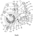
- the second toothed sector 70 is also rotated in the anti-clockwise direction and rotates the mobile display of the date 18 of a step, as illustrated on the figure 6b To indicate the 28 th of the current month.
- the second board 56 meanwhile, also remains immobile during this operation.
- the second toothed sector 70 has three teeth facing the inactive space 58 in the configuration of the figure 6b , then two in that of the Figure 6c and only one in the configuration of the figure 6d .
- the two toothed sectors 68 and 70 are found in their initial position in the configuration of the figure 6d , that is, in the position they occupy prior to programming. This is also apparent from the position of the pin 82 in the slot 86 that it travels, insofar as it reaches, at this stage, the end of the slot 86 that it occupies when the first toothed sector 68 is in its abutment position, as shown in Figure 2c .
- the first toothed sector 68 drives the first plank 50 with it, as well as the second plank 56 and the second toothed sector 70.
- the last tooth of the second toothed sector 70 releases the display mobile of the date 18 opposite which is still an empty space corresponding to two steps.
- the mobile calendar 18 of the display can then perform its retrograde movement under the effect of the action of a spiral spring 132 here, by way of illustration without limitation, to display the 1st day of the following month, as shown in figure 6e .
- the first board 50 having this time turned one step, it presents again a tooth within range of the actuating nose 114, ready to receive a pulse on the next turn of the wheel 24 hours.
- the second board 56 since the second board 56 has advanced one step, it also has a tooth 62 within range of the first tooth 134 of the toothing of the date display mobile 18, this tooth 134 having dimensions greater than those of the other teeth of the mobile 18 to define a stop for the mobile, when returning to the 1st of the following month, while allowing the other teeth to pass next to the first tooth 62 of the second board 56.
- the programming mobile 20 performs a complete turn on itself in a period of one month, regardless of the duration of each month, and that the same goes for the wheel of the month 24 which controls the Displacement of the display mobile of the months 22 carrying the cam of months 36 which defines the programming of the mobile programming 20 each month.
- the cooperation between the trigger member 120 and the periphery of the supplementary board 64 defines a stop in the counterclockwise direction, when the flip-flop 16 is returned to its position after each change of date (except for the 25th). .
- a relatively simple programming mobile is obtained that is easy to build and to adjust and that offers a great flexibility of use, making it possible to implement it in relationship with a large number of applications, such as in a countdown mechanism.
- this programming mobile can be performed automatically, controlled by the watch movement, as has been described in the context of its application to a calendar mechanism, or manually.
- a basic duration could be provided for any count to which the user could add additional time when desired, by actuating the programming cam controlling the amplitude of rotation of the rocker 16 during programming operations.
- the forms illustrated and described for the scales 16 and 38 and their mode of cooperation are not limiting and the skilled person will not encounter any particular difficulty to adapt the described construction according to his own needs without departing from the scope of the present invention.
- a certain number of abutment surfaces that have been described and illustrated are optional and those skilled in the art will be able to provide as many as necessary according to their needs.
- the first and second sectors toothed are not necessarily integral insofar as it is sufficient that the movements of the second tooth sector, output, are dictated by those of the first gear sector, input.
Landscapes
- Physics & Mathematics (AREA)
- General Physics & Mathematics (AREA)
- Electromechanical Clocks (AREA)
- Transceivers (AREA)
Claims (18)
- Mobile Programmierungsvorrichtung (20) für Uhrwerk (1), verfügend übereine erste Platte (50) mit einer Zahnung, die mit einem Betätigungselement (114) zusammenwirken soll, um ein Drehen die gesagte erste Platte (50) in eine festgelegte Drehrichtung zu ermöglichen,eine zweite Platte (56), koaxial zu der gesagten ersten Platte (50), mit dieser drehfest verbunden, und mit einer Zahnung zur Betätigung eines Mechanismus (18) des Uhrwerks (1),einen ersten Zahnsektor (68), der im Verhältnis zu der gesagten ersten Platte (50) schwenkbar ist und über n+1 Zähne verfügt, wobei n größer als oder gleich 1 ist, mit deren Hilfe er mit dem Betätigungselement (114) zusammenwirken soll, wobei der gesagte erste Zahnsektor (68) sich im Verhältnis zu der gesagten ersten Platte (50) in n+1 verschiedenen Winkelpositionen befinden kann,dadurch gekennzeichnet, dass die Zahnung der gesagten ersten Platte (50) über einen inaktiven Bereich (52) verfügt, der mindestens einem Schritt entspricht, wobei der gesagte erste Zahnsektor (68) mit dem Betätigungselement (114) zusammenwirken kann, während die gesagte erste Platte (50) im Hinblick auf die Betätigungsvorrichtung (114) diesen inaktiven Bereich (52) darstellt,dass die gesagte n+1 Winkelpositionen des gesagten ersten Zahnsektors (68) auf jeder Seite des gesagten inaktiven Bereichs (52) verteilt sind, und über eine erste Anschlagsposition verfügen, in der eine Drehung des gesagten ersten Zahnsektors (68) durch die Wirkung der Betätigungselement (114) in die gesagte festgelegte Drehrichtung eine Drehung der gesagten ersten Platte (50) überträgt, sowie n im Voraus im Rahmen eines Programmierungsvorgangs programmierte Positionen, und in welchen der gesagte erste Zahnsektor (68) positioniert werden kann, um um 0 bis n zusätzliche Schritte durch das Betätigungselement (114) gedreht werden zu können, ohne dass die gesagte erste Platte (50) gedreht wird, unddass die gesagte mobile Programmierungsvorrichtung (20) darüber hinaus über einen zweiten Zahnsektor (70) verfügt, der über mindestens n+1 Zähne verfügt, so angeordnet, dass er im Verhältnis zu der gesagten zweiten Platte (56) je nach Drehbewegungen des gesagten ersten Zahnsektors (68) schwenkbar ist und mit dem Mechanismus (18) des Uhrwerks (1) zusammenwirken soll, um ihn bei jeder abgeschlossenen Drehung der gesagten ersten Platte (50) um weitere 0 bis n Mal zu betätigen.
- Mobile Vorrichtung (20) nach Anspruch 1, dadurch gekennzeichnet, dass der gesagte erste Zahnsektor (68) und der gesagte zweite Zahnsektor (70) miteinander fest verbunden sind.
- Mobile Vorrichtung (20) nach Anspruch 1 und 2,dadurch gekennzeichnet, dass die Zahnung der gesagten zweiten Platte (56) ebenfalls über einen inaktiven Bereich (58) verfügt, der mindestens einem Schritt entspricht, wobei die jeweiligen inaktiven Bereiche (52, 58) der gesagten ersten und zweiten Platte (50, 56) sich in einer festgelegten relativen Winkelposition befinden, unddass der gesagte zweite Zahnsektor (70) so angeordnet ist, dass er sich in n+1 verschiedenen Winkelpositionen im Verhältnis zu der gesagten zweiten Platte (56) befinden kann, bzw. im Verhältnis zu den n+1 Winkelpositionen des gesagten ersten Zahnsektors (68) und auf jeder Seite des inaktiven Bereichs (58) der Zahnung der gesagten zweiten Platte (56) verteilt.
- Mobile Vorrichtung (20) nach Anspruch 3, dadurch gekennzeichnet, dass der inaktive Bereich (58) der Zahnung der gesagten zweiten Platte (56) mindestens drei Schritten entspricht.
- Mobile Vorrichtung (20) nach einem der vorstehenden Ansprüche, dadurch gekennzeichnet, dass die Gesamtheit des gesagten ersten Zahnsektors (68) und des gesagten zweiten Zahnsektors (70) einen Teil aufweist, der in der gesagten Anschlagsposition des gesagten ersten Zahnsektors (68) gegen eine blockierende Fläche (102) anschlagend angeordnet ist, die mit der gesagten ersten Platte (50) oder der gesagten zweiten Platte (56) fest verbunden ist.
- Mobile Vorrichtung (20) nach einem der Ansprüche 3 bis 5, dadurch gekennzeichnet, dass sowohl die gesagte erste als auch die gesagte zweite Platte (50, 56) über eine Aussparung verfügen (72, 74), deren Tiefe mindestens so groß wie die Höhe ist bzw. von dem gesagten ersten Zahnsektor (68) und dem gesagten zweiten Zahnsektor (70) und insbesondere bis zur entsprechenden Zahnung, und zwar so,dass die Zahnung der gesagten ersten und der gesagten zweiten Platte (50, 56) mindestens einen Zahn aufweist, und zwar auf jeder Seite des entsprechenden inaktiven Bereichs (52, 58), dessen Höhe im Verhältnis zu seinen anderen Zähnen reduziert ist, unddass der gesagte erste Zahnsektor (68) und der gesagte zweite (70) sich in der Höhe befinden können bzw. von der gesagten ersten Platte (50) und der gesagten zweiten Platte (56).
- Mobile Vorrichtung (20) gemäß einem der vorstehenden Ansprüche, dadurch gekennzeichnet, dass sie über eine Ratsche (94) verfügt, die mit der gesagten ersten oder mit der gesagten zweiten Platte (50, 56) drehfest verbunden und so angeordnet ist, dass sie mit dem gesagten ersten oder mit dem gesagten zweiten Zahnsektor (68, 70) zusammenwirkt, um diese n+1 Winkelpositionen des gesagten ersten Zahnsektors (68) zu bilden.
- Mobile Vorrichtung (20) gemäß einem der vorstehenden Ansprüche, dadurch gekennzeichnet, dass sie über eine Betätigungsfläche (82) verfügt, die mit dem gesagten ersten oder dem gesagten zweiten Zahnsektor (68, 70) fest verbunden ist, und durch ein Programmierungsorgan (112) des Uhrwerks (1) betätigt werden soll, um den gesagten ersten und zweiten Zahnsektoren (68, 70) in einer ihrer n+1 Winkelpositionen im Verhältnis zu der gesagten ersten und gesagten zweiten Platte (50, 56) zu positionieren, sowie eine Auslösefläche (66), die mit der gesagten ersten oder mit der gesagten zweiten Platte (50, 56) fest verbunden ist und die Betätigung des Programmierungsorgans ermöglichen soll.
- Mobile Vorrichtung (20) nach einem der vorstehenden Ansprüche, dadurch gekennzeichnet, dass die gesagte Auslösefläche (66) in einer zusätzlichen Platte (64) angeordnet ist, die mit der gesagten ersten und der gesagten zweiten Platte (50, 56) drehfest verbunden ist.
- Programmierungsmechanismus, verfügend über eine mobile Programmierungsvorrichtung (20) gemäß einem der Ansprüche 1 bis 9, dadurch gekennzeichnet, dass es über ein Programmierungsorgan (112) verfügt, das, periodisch oder auf Wunsch, mit den gesagten Zahnsektoren (68, 70) oder mindestens mit einem davon zusammenwirkt, um beim Programmieren den gesagten ersten Zahnsektor (68) in eine der gesagten n+1 Winkelpositionen im Verhältnis zu der gesagten ersten und zweiten Platte (50, 56) zu bringen.
- Mechanismus nach Anspruch 10, die gesagte mobile Programmierungsvorrichtung (20), die über eine Betätigungsfläche (82) verfügt, die mit dem gesagten ersten oder dem gesagten zweiten Zahnsektor (68, 70) verbunden ist, und durch das gesagte Programmierungsorgan (112) betätigt werden soll, sowie eine Auslösefläche (66), die mit der gesagten ersten oder der gesagten zweiten Platte (50, 56) fest verbunden ist, dadurch gekennzeichnet, dass sie darüber hinaus über ein Auslöseelement (120) verfügt, das mit diesem Programmierungsorgan (112) fest verbunden ist und so angeordnet ist, dass es mit der gesagten Auslösefläche (66) zusammenwirkt und dieses Programmierungsorgan (112) dazu bringt, auf diese Betätigungsfläche (82) einzuwirken.
- Mechanismus nach Anspruch 11, wobei die gesagte Auslösefläche (66) in einer zusätzlichen Platte (64) angeordnet ist, die mit der gesagten ersten und gesagten zweiten Platte (50, 56) drehfest verbunden ist, dadurch gekennzeichnet,dass die gesagte zusätzliche Platte (64) deutlich die Form einer Scheibe aufweist, die einen Schlitz hat, welcher am Rande der Scheibe beginnt, um die gesagte Auslösefläche (66) zu definieren, unddass der Mechanismus über ein elastisches Element verfügt, das das gesagte Auslöseelement (120) gegen den Rand der gesagten zusätzlichen Platte (64) gedrückt hält, und zwar so, dass es in diesen Auslöseschlitz (66) eindringt, wenn diese sich ihm gegenüber befindet, um die Einwirkung des gesagten Programmierungsorgans zu gewährleisten.
- Mechanismus nach Anspruch 12, dadurch gekennzeichnet, dass das gesagte Programmierungsorgan (112) und das gesagte Auslöseelement (120) auf einem Flipflop (16) angeordnet sind, und dass er darüber hinaus über einen Fühler (40) verfügt, der so angeordnet ist, dass er mit einer Programmier-Nockenbahn (36) zusammenwirkt, die so angeordnet ist, dass sie während des Programmierungsvorgangs bei jeder kompletten Umdrehung der gesagten ersten Platte (50) die Rotationsamplitude des gesagten Flipflops (16) definiert.
- Mechanismus nach Anspruch 13, bei dem sich das gesagte Flipflop (16) während des gesagten Programmierungsvorgangs in eine erste Drehrichtung dreht, dadurch gekennzeichnet, dass das gesagte Flipflop (16)über eine erste Fläche (110) verfügt, die durch ein Antriebselement (14) des Uhrwerks betätigt werden soll, um das gesagte Flipflop (16) in die dem gesagten Programmierungsvorgang entgegengesetzte Richtung zu drehen,sowie über eine zweite Fläche verfügt, die das gesagte Betätigungselement (114) definiert, das auf die Zahnung der gesagten ersten Platte (50) und/oder auf den gesagten ersten Zahnsektor (68) einwirkt, während sich das gesagte Flipflop (16) in die entgegengesetzte Richtung dreht.
- Uhrwerk, das über ein Antriebselement (14) verfügt, das so angeordnet ist, dass es eine mobile Anzeige (18) mittels eines Programmierungsmechanismus gemäß einem der Ansprüche 10 bis 14 betätigt.
- Uhrwerk nach Anspruch 15, in dem die Zahnung der gesagten zweiten Platte (56) über einen inaktiven Bereich (58) verfügt, der mindestens drei Schritten entspricht, dadurch gekennzeichnet, dass es sich um eine mobile Anzeige (18) des retrograden Typs handelt.
- Uhrwerk nach Anspruch 15 oder 16, dadurch gekennzeichnet, dass die gesagte mobile Anzeige eine mobile Anzeige des Monatsdatums ist oder eine zeitlich beschränkte Zählung ermöglicht.
- Uhrwerk nach Anspruch 15 oder 16, dadurch gekennzeichnet, dass der gesagte Mechanismus so angeordnet ist, dass die gesagte mobile Anzeige (18) zum Anzeigen des ewigen Kalenders dienen kann.
Applications Claiming Priority (1)
| Application Number | Priority Date | Filing Date | Title |
|---|---|---|---|
| CH01551/15A CH711679A2 (fr) | 2015-10-23 | 2015-10-23 | Mobile de programmation pour mouvement horloger. |
Publications (3)
| Publication Number | Publication Date |
|---|---|
| EP3159752A2 EP3159752A2 (de) | 2017-04-26 |
| EP3159752A3 EP3159752A3 (de) | 2017-08-30 |
| EP3159752B1 true EP3159752B1 (de) | 2019-03-27 |
Family
ID=57103923
Family Applications (1)
| Application Number | Title | Priority Date | Filing Date |
|---|---|---|---|
| EP16192609.2A Active EP3159752B1 (de) | 2015-10-23 | 2016-10-06 | Mobiles programmiergerät für uhrwerk |
Country Status (2)
| Country | Link |
|---|---|
| EP (1) | EP3159752B1 (de) |
| CH (1) | CH711679A2 (de) |
Families Citing this family (1)
| Publication number | Priority date | Publication date | Assignee | Title |
|---|---|---|---|---|
| RU2724959C1 (ru) * | 2020-01-17 | 2020-06-29 | Константин Юрьевич Чайкин | Часы с вечным марсианским календарем |
Family Cites Families (4)
| Publication number | Priority date | Publication date | Assignee | Title |
|---|---|---|---|---|
| EP1351104B1 (de) | 2002-04-02 | 2008-11-26 | Ulysse Nardin S.A. | Vorrichtung mit Programmrad für den Mechanismus eines ewigen Kalenders sowie Uhr mit solchem Mechanismus |
| EP1868047A1 (de) | 2006-06-12 | 2007-12-19 | Vaucher Manufacture Fleurier SA | Uhr mit einem Kalendarmechanismus |
| CH704506A2 (fr) * | 2011-02-17 | 2012-08-31 | Glashuetter Uhrenbetrieb Gmbh | Dispositif à roue de programme pour mécanisme de calendrier et mécanisme de calendrier perpétuel comportant un tel dispositif. |
| EP2490082B1 (de) * | 2011-02-17 | 2013-09-18 | Glashütter Uhrenbetrieb GmbH | Kalendersmechanismus |
-
2015
- 2015-10-23 CH CH01551/15A patent/CH711679A2/fr not_active Application Discontinuation
-
2016
- 2016-10-06 EP EP16192609.2A patent/EP3159752B1/de active Active
Non-Patent Citations (1)
| Title |
|---|
| None * |
Also Published As
| Publication number | Publication date |
|---|---|
| EP3159752A3 (de) | 2017-08-30 |
| EP3159752A2 (de) | 2017-04-26 |
| CH711679A2 (fr) | 2017-04-28 |
Similar Documents
| Publication | Publication Date | Title |
|---|---|---|
| EP1586962B1 (de) | Perpetual calendar mechanism | |
| EP2073076B1 (de) | Betätigungsmechanismus eines weckers | |
| EP2503410B1 (de) | Kalendermechanismus, der einen Monatsschnellkorrektor umfasst | |
| EP2180383B1 (de) | Hilfsvorrichtung zur Positionshaltung einer Datumsanzeigescheibe für Uhrwerk | |
| EP2407833B1 (de) | Spielausgleichsmechanismus für Uhrwerk | |
| EP2776894B1 (de) | Mechanismus zur ansteuerung eines indikators | |
| EP3043217B1 (de) | Vorrichtung zum antrieben einen drehteil eines kalender-uhrwerkmechanismus | |
| EP3602202B1 (de) | Vorrichtung zur einstellung von funktionen einer uhr | |
| EP1596261A1 (de) | Jährlicher Kalendermechanismus für Uhrwerk | |
| EP3008523B1 (de) | Kalendermechanismus für ein uhrwerk | |
| CH712219A2 (fr) | Mécanisme pour mouvement de montre à affichage rétrograde et sautant. | |
| EP3629102B1 (de) | Anzeigemechanismus mit einer fensteranzeige | |
| EP3159752B1 (de) | Mobiles programmiergerät für uhrwerk | |
| CH699794B1 (fr) | Dispositif d'aide au maintien en position d'un anneau indicateur de quantième pour pièce d'horlogerie. | |
| EP3644130A1 (de) | Datumsmechanismus | |
| CH712032A2 (fr) | Mécanisme de commande pour mouvement horloger. | |
| CH691086A5 (fr) | Mouvement d'horlogerie à quantième perpétuel. | |
| EP1734419B1 (de) | Uhr mit Kalendermechanismus | |
| EP2710433A1 (de) | Betätigungsmechanismus für ein uhrwerk und entsprechendes uhrwerk | |
| EP3460588B1 (de) | Datumsmechanismus | |
| EP3845973A1 (de) | Uhrwerk, das für den antrieb in einer variablen anzahl von schritten konzipiert ist | |
| EP4356203B1 (de) | Kalendermechanismus mit jahreszeitenanzeige für uhren | |
| CH718804B1 (fr) | Mécanisme de quantième perpétuel ou annuel. | |
| CH719977B1 (fr) | Mécanisme horloger à affichage sautant | |
| EP3588201A1 (de) | Jahreskalendermechanismus für uhrwerk |
Legal Events
| Date | Code | Title | Description |
|---|---|---|---|
| PUAI | Public reference made under article 153(3) epc to a published international application that has entered the european phase |
Free format text: ORIGINAL CODE: 0009012 |
|
| STAA | Information on the status of an ep patent application or granted ep patent |
Free format text: STATUS: THE APPLICATION HAS BEEN PUBLISHED |
|
| AK | Designated contracting states |
Kind code of ref document: A2 Designated state(s): AL AT BE BG CH CY CZ DE DK EE ES FI FR GB GR HR HU IE IS IT LI LT LU LV MC MK MT NL NO PL PT RO RS SE SI SK SM TR |
|
| AX | Request for extension of the european patent |
Extension state: BA ME |
|
| PUAL | Search report despatched |
Free format text: ORIGINAL CODE: 0009013 |
|
| AK | Designated contracting states |
Kind code of ref document: A3 Designated state(s): AL AT BE BG CH CY CZ DE DK EE ES FI FR GB GR HR HU IE IS IT LI LT LU LV MC MK MT NL NO PL PT RO RS SE SI SK SM TR |
|
| AX | Request for extension of the european patent |
Extension state: BA ME |
|
| RIC1 | Information provided on ipc code assigned before grant |
Ipc: G04B 19/253 20060101AFI20170724BHEP |
|
| RBV | Designated contracting states (corrected) |
Designated state(s): AL AT BE BG CH CY CZ DE DK EE ES FI FR GB GR HR HU IE IS IT LI LT LU LV MC MK MT NL NO PL PT RO RS SE SI SK SM TR |
|
| STAA | Information on the status of an ep patent application or granted ep patent |
Free format text: STATUS: REQUEST FOR EXAMINATION WAS MADE |
|
| 17P | Request for examination filed |
Effective date: 20180309 |
|
| R17P | Request for examination filed (corrected) |
Effective date: 20180226 |
|
| GRAP | Despatch of communication of intention to grant a patent |
Free format text: ORIGINAL CODE: EPIDOSNIGR1 |
|
| STAA | Information on the status of an ep patent application or granted ep patent |
Free format text: STATUS: GRANT OF PATENT IS INTENDED |
|
| INTG | Intention to grant announced |
Effective date: 20181012 |
|
| GRAS | Grant fee paid |
Free format text: ORIGINAL CODE: EPIDOSNIGR3 |
|
| GRAA | (expected) grant |
Free format text: ORIGINAL CODE: 0009210 |
|
| STAA | Information on the status of an ep patent application or granted ep patent |
Free format text: STATUS: THE PATENT HAS BEEN GRANTED |
|
| AK | Designated contracting states |
Kind code of ref document: B1 Designated state(s): AL AT BE BG CH CY CZ DE DK EE ES FI FR GB GR HR HU IE IS IT LI LT LU LV MC MK MT NL NO PL PT RO RS SE SI SK SM TR |
|
| REG | Reference to a national code |
Ref country code: GB Ref legal event code: FG4D Free format text: NOT ENGLISH |
|
| REG | Reference to a national code |
Ref country code: CH Ref legal event code: EP |
|
| REG | Reference to a national code |
Ref country code: AT Ref legal event code: REF Ref document number: 1113803 Country of ref document: AT Kind code of ref document: T Effective date: 20190415 |
|
| REG | Reference to a national code |
Ref country code: IE Ref legal event code: FG4D Free format text: LANGUAGE OF EP DOCUMENT: FRENCH |
|
| REG | Reference to a national code |
Ref country code: DE Ref legal event code: R096 Ref document number: 602016011506 Country of ref document: DE |
|
| REG | Reference to a national code |
Ref country code: CH Ref legal event code: NV Representative=s name: E-PATENT S.A., CH |
|
| PG25 | Lapsed in a contracting state [announced via postgrant information from national office to epo] |
Ref country code: SE Free format text: LAPSE BECAUSE OF FAILURE TO SUBMIT A TRANSLATION OF THE DESCRIPTION OR TO PAY THE FEE WITHIN THE PRESCRIBED TIME-LIMIT Effective date: 20190327 Ref country code: FI Free format text: LAPSE BECAUSE OF FAILURE TO SUBMIT A TRANSLATION OF THE DESCRIPTION OR TO PAY THE FEE WITHIN THE PRESCRIBED TIME-LIMIT Effective date: 20190327 Ref country code: NO Free format text: LAPSE BECAUSE OF FAILURE TO SUBMIT A TRANSLATION OF THE DESCRIPTION OR TO PAY THE FEE WITHIN THE PRESCRIBED TIME-LIMIT Effective date: 20190627 Ref country code: LT Free format text: LAPSE BECAUSE OF FAILURE TO SUBMIT A TRANSLATION OF THE DESCRIPTION OR TO PAY THE FEE WITHIN THE PRESCRIBED TIME-LIMIT Effective date: 20190327 |
|
| REG | Reference to a national code |
Ref country code: NL Ref legal event code: MP Effective date: 20190327 |
|
| PG25 | Lapsed in a contracting state [announced via postgrant information from national office to epo] |
Ref country code: GR Free format text: LAPSE BECAUSE OF FAILURE TO SUBMIT A TRANSLATION OF THE DESCRIPTION OR TO PAY THE FEE WITHIN THE PRESCRIBED TIME-LIMIT Effective date: 20190628 Ref country code: HR Free format text: LAPSE BECAUSE OF FAILURE TO SUBMIT A TRANSLATION OF THE DESCRIPTION OR TO PAY THE FEE WITHIN THE PRESCRIBED TIME-LIMIT Effective date: 20190327 Ref country code: NL Free format text: LAPSE BECAUSE OF FAILURE TO SUBMIT A TRANSLATION OF THE DESCRIPTION OR TO PAY THE FEE WITHIN THE PRESCRIBED TIME-LIMIT Effective date: 20190327 Ref country code: LV Free format text: LAPSE BECAUSE OF FAILURE TO SUBMIT A TRANSLATION OF THE DESCRIPTION OR TO PAY THE FEE WITHIN THE PRESCRIBED TIME-LIMIT Effective date: 20190327 Ref country code: BG Free format text: LAPSE BECAUSE OF FAILURE TO SUBMIT A TRANSLATION OF THE DESCRIPTION OR TO PAY THE FEE WITHIN THE PRESCRIBED TIME-LIMIT Effective date: 20190627 Ref country code: RS Free format text: LAPSE BECAUSE OF FAILURE TO SUBMIT A TRANSLATION OF THE DESCRIPTION OR TO PAY THE FEE WITHIN THE PRESCRIBED TIME-LIMIT Effective date: 20190327 |
|
| REG | Reference to a national code |
Ref country code: AT Ref legal event code: MK05 Ref document number: 1113803 Country of ref document: AT Kind code of ref document: T Effective date: 20190327 |
|
| PG25 | Lapsed in a contracting state [announced via postgrant information from national office to epo] |
Ref country code: RO Free format text: LAPSE BECAUSE OF FAILURE TO SUBMIT A TRANSLATION OF THE DESCRIPTION OR TO PAY THE FEE WITHIN THE PRESCRIBED TIME-LIMIT Effective date: 20190327 Ref country code: CZ Free format text: LAPSE BECAUSE OF FAILURE TO SUBMIT A TRANSLATION OF THE DESCRIPTION OR TO PAY THE FEE WITHIN THE PRESCRIBED TIME-LIMIT Effective date: 20190327 Ref country code: IT Free format text: LAPSE BECAUSE OF FAILURE TO SUBMIT A TRANSLATION OF THE DESCRIPTION OR TO PAY THE FEE WITHIN THE PRESCRIBED TIME-LIMIT Effective date: 20190327 Ref country code: EE Free format text: LAPSE BECAUSE OF FAILURE TO SUBMIT A TRANSLATION OF THE DESCRIPTION OR TO PAY THE FEE WITHIN THE PRESCRIBED TIME-LIMIT Effective date: 20190327 Ref country code: ES Free format text: LAPSE BECAUSE OF FAILURE TO SUBMIT A TRANSLATION OF THE DESCRIPTION OR TO PAY THE FEE WITHIN THE PRESCRIBED TIME-LIMIT Effective date: 20190327 Ref country code: AL Free format text: LAPSE BECAUSE OF FAILURE TO SUBMIT A TRANSLATION OF THE DESCRIPTION OR TO PAY THE FEE WITHIN THE PRESCRIBED TIME-LIMIT Effective date: 20190327 Ref country code: PT Free format text: LAPSE BECAUSE OF FAILURE TO SUBMIT A TRANSLATION OF THE DESCRIPTION OR TO PAY THE FEE WITHIN THE PRESCRIBED TIME-LIMIT Effective date: 20190727 Ref country code: SK Free format text: LAPSE BECAUSE OF FAILURE TO SUBMIT A TRANSLATION OF THE DESCRIPTION OR TO PAY THE FEE WITHIN THE PRESCRIBED TIME-LIMIT Effective date: 20190327 |
|
| PG25 | Lapsed in a contracting state [announced via postgrant information from national office to epo] |
Ref country code: PL Free format text: LAPSE BECAUSE OF FAILURE TO SUBMIT A TRANSLATION OF THE DESCRIPTION OR TO PAY THE FEE WITHIN THE PRESCRIBED TIME-LIMIT Effective date: 20190327 Ref country code: SM Free format text: LAPSE BECAUSE OF FAILURE TO SUBMIT A TRANSLATION OF THE DESCRIPTION OR TO PAY THE FEE WITHIN THE PRESCRIBED TIME-LIMIT Effective date: 20190327 |
|
| PG25 | Lapsed in a contracting state [announced via postgrant information from national office to epo] |
Ref country code: AT Free format text: LAPSE BECAUSE OF FAILURE TO SUBMIT A TRANSLATION OF THE DESCRIPTION OR TO PAY THE FEE WITHIN THE PRESCRIBED TIME-LIMIT Effective date: 20190327 Ref country code: IS Free format text: LAPSE BECAUSE OF FAILURE TO SUBMIT A TRANSLATION OF THE DESCRIPTION OR TO PAY THE FEE WITHIN THE PRESCRIBED TIME-LIMIT Effective date: 20190727 |
|
| REG | Reference to a national code |
Ref country code: DE Ref legal event code: R097 Ref document number: 602016011506 Country of ref document: DE |
|
| PG25 | Lapsed in a contracting state [announced via postgrant information from national office to epo] |
Ref country code: DK Free format text: LAPSE BECAUSE OF FAILURE TO SUBMIT A TRANSLATION OF THE DESCRIPTION OR TO PAY THE FEE WITHIN THE PRESCRIBED TIME-LIMIT Effective date: 20190327 |
|
| PLBE | No opposition filed within time limit |
Free format text: ORIGINAL CODE: 0009261 |
|
| STAA | Information on the status of an ep patent application or granted ep patent |
Free format text: STATUS: NO OPPOSITION FILED WITHIN TIME LIMIT |
|
| PG25 | Lapsed in a contracting state [announced via postgrant information from national office to epo] |
Ref country code: SI Free format text: LAPSE BECAUSE OF FAILURE TO SUBMIT A TRANSLATION OF THE DESCRIPTION OR TO PAY THE FEE WITHIN THE PRESCRIBED TIME-LIMIT Effective date: 20190327 |
|
| 26N | No opposition filed |
Effective date: 20200103 |
|
| PG25 | Lapsed in a contracting state [announced via postgrant information from national office to epo] |
Ref country code: TR Free format text: LAPSE BECAUSE OF FAILURE TO SUBMIT A TRANSLATION OF THE DESCRIPTION OR TO PAY THE FEE WITHIN THE PRESCRIBED TIME-LIMIT Effective date: 20190327 |
|
| REG | Reference to a national code |
Ref country code: DE Ref legal event code: R119 Ref document number: 602016011506 Country of ref document: DE |
|
| PG25 | Lapsed in a contracting state [announced via postgrant information from national office to epo] |
Ref country code: MC Free format text: LAPSE BECAUSE OF FAILURE TO SUBMIT A TRANSLATION OF THE DESCRIPTION OR TO PAY THE FEE WITHIN THE PRESCRIBED TIME-LIMIT Effective date: 20190327 |
|
| PG25 | Lapsed in a contracting state [announced via postgrant information from national office to epo] |
Ref country code: LU Free format text: LAPSE BECAUSE OF NON-PAYMENT OF DUE FEES Effective date: 20191006 Ref country code: DE Free format text: LAPSE BECAUSE OF NON-PAYMENT OF DUE FEES Effective date: 20200501 |
|
| REG | Reference to a national code |
Ref country code: BE Ref legal event code: MM Effective date: 20191031 |
|
| PG25 | Lapsed in a contracting state [announced via postgrant information from national office to epo] |
Ref country code: BE Free format text: LAPSE BECAUSE OF NON-PAYMENT OF DUE FEES Effective date: 20191031 |
|
| PG25 | Lapsed in a contracting state [announced via postgrant information from national office to epo] |
Ref country code: IE Free format text: LAPSE BECAUSE OF NON-PAYMENT OF DUE FEES Effective date: 20191006 Ref country code: FR Free format text: LAPSE BECAUSE OF NON-PAYMENT OF DUE FEES Effective date: 20191031 |
|
| PG25 | Lapsed in a contracting state [announced via postgrant information from national office to epo] |
Ref country code: CY Free format text: LAPSE BECAUSE OF FAILURE TO SUBMIT A TRANSLATION OF THE DESCRIPTION OR TO PAY THE FEE WITHIN THE PRESCRIBED TIME-LIMIT Effective date: 20190327 |
|
| GBPC | Gb: european patent ceased through non-payment of renewal fee |
Effective date: 20201006 |
|
| PG25 | Lapsed in a contracting state [announced via postgrant information from national office to epo] |
Ref country code: HU Free format text: LAPSE BECAUSE OF FAILURE TO SUBMIT A TRANSLATION OF THE DESCRIPTION OR TO PAY THE FEE WITHIN THE PRESCRIBED TIME-LIMIT; INVALID AB INITIO Effective date: 20161006 Ref country code: MT Free format text: LAPSE BECAUSE OF FAILURE TO SUBMIT A TRANSLATION OF THE DESCRIPTION OR TO PAY THE FEE WITHIN THE PRESCRIBED TIME-LIMIT Effective date: 20190327 |
|
| PG25 | Lapsed in a contracting state [announced via postgrant information from national office to epo] |
Ref country code: GB Free format text: LAPSE BECAUSE OF NON-PAYMENT OF DUE FEES Effective date: 20201006 |
|
| PG25 | Lapsed in a contracting state [announced via postgrant information from national office to epo] |
Ref country code: MK Free format text: LAPSE BECAUSE OF FAILURE TO SUBMIT A TRANSLATION OF THE DESCRIPTION OR TO PAY THE FEE WITHIN THE PRESCRIBED TIME-LIMIT Effective date: 20190327 |
|
| REG | Reference to a national code |
Ref country code: CH Ref legal event code: U11 Free format text: ST27 STATUS EVENT CODE: U-0-0-U10-U11 (AS PROVIDED BY THE NATIONAL OFFICE) Effective date: 20251101 |
|
| PGFP | Annual fee paid to national office [announced via postgrant information from national office to epo] |
Ref country code: CH Payment date: 20251101 Year of fee payment: 10 |