EP3374774B1 - Vorrichtung zum schütteln und entnehmen biologischer flüssigkeitsproben mit eignung zum sortieren - Google Patents
Vorrichtung zum schütteln und entnehmen biologischer flüssigkeitsproben mit eignung zum sortieren Download PDFInfo
- Publication number
- EP3374774B1 EP3374774B1 EP16809975.2A EP16809975A EP3374774B1 EP 3374774 B1 EP3374774 B1 EP 3374774B1 EP 16809975 A EP16809975 A EP 16809975A EP 3374774 B1 EP3374774 B1 EP 3374774B1
- Authority
- EP
- European Patent Office
- Prior art keywords
- tube
- rack
- destination data
- tubes
- racks
- Prior art date
- Legal status (The legal status is an assumption and is not a legal conclusion. Google has not performed a legal analysis and makes no representation as to the accuracy of the status listed.)
- Active
Links
Images



Classifications
-
- G—PHYSICS
- G01—MEASURING; TESTING
- G01N—INVESTIGATING OR ANALYSING MATERIALS BY DETERMINING THEIR CHEMICAL OR PHYSICAL PROPERTIES
- G01N35/00—Automatic analysis not limited to methods or materials provided for in any single one of groups G01N1/00 - G01N33/00; Handling materials therefor
- G01N35/00584—Control arrangements for automatic analysers
- G01N35/00722—Communications; Identification
- G01N35/00732—Identification of carriers, materials or components in automatic analysers
-
- B—PERFORMING OPERATIONS; TRANSPORTING
- B01—PHYSICAL OR CHEMICAL PROCESSES OR APPARATUS IN GENERAL
- B01F—MIXING, e.g. DISSOLVING, EMULSIFYING OR DISPERSING
- B01F29/00—Mixers with rotating receptacles
- B01F29/30—Mixing the contents of individual packages or containers, e.g. by rotating tins or bottles
- B01F29/32—Containers specially adapted for coupling to rotating frames or the like; Coupling means therefor
- B01F29/321—Containers specially adapted for coupling to rotating frames or the like; Coupling means therefor of test-tubes or the like
-
- B—PERFORMING OPERATIONS; TRANSPORTING
- B01—PHYSICAL OR CHEMICAL PROCESSES OR APPARATUS IN GENERAL
- B01L—CHEMICAL OR PHYSICAL LABORATORY APPARATUS FOR GENERAL USE
- B01L3/00—Containers or dishes for laboratory use, e.g. laboratory glassware; Droppers
- B01L3/50—Containers for the purpose of retaining a material to be analysed, e.g. test tubes
- B01L3/502—Containers for the purpose of retaining a material to be analysed, e.g. test tubes with fluid transport, e.g. in multi-compartment structures
- B01L3/5025—Containers for the purpose of retaining a material to be analysed, e.g. test tubes with fluid transport, e.g. in multi-compartment structures for parallel transport of multiple samples
-
- G—PHYSICS
- G01—MEASURING; TESTING
- G01N—INVESTIGATING OR ANALYSING MATERIALS BY DETERMINING THEIR CHEMICAL OR PHYSICAL PROPERTIES
- G01N35/00—Automatic analysis not limited to methods or materials provided for in any single one of groups G01N1/00 - G01N33/00; Handling materials therefor
- G01N35/00584—Control arrangements for automatic analysers
- G01N35/0092—Scheduling
-
- G—PHYSICS
- G01—MEASURING; TESTING
- G01N—INVESTIGATING OR ANALYSING MATERIALS BY DETERMINING THEIR CHEMICAL OR PHYSICAL PROPERTIES
- G01N35/00—Automatic analysis not limited to methods or materials provided for in any single one of groups G01N1/00 - G01N33/00; Handling materials therefor
- G01N35/0099—Automatic analysis not limited to methods or materials provided for in any single one of groups G01N1/00 - G01N33/00; Handling materials therefor comprising robots or similar manipulators
-
- G—PHYSICS
- G01—MEASURING; TESTING
- G01N—INVESTIGATING OR ANALYSING MATERIALS BY DETERMINING THEIR CHEMICAL OR PHYSICAL PROPERTIES
- G01N35/00—Automatic analysis not limited to methods or materials provided for in any single one of groups G01N1/00 - G01N33/00; Handling materials therefor
- G01N35/10—Devices for transferring samples or any liquids to, in, or from, the analysis apparatus, e.g. suction devices, injection devices
- G01N35/1081—Devices for transferring samples or any liquids to, in, or from, the analysis apparatus, e.g. suction devices, injection devices characterised by the means for relatively moving the transfer device and the containers in an horizontal plane
- G01N35/1083—Devices for transferring samples or any liquids to, in, or from, the analysis apparatus, e.g. suction devices, injection devices characterised by the means for relatively moving the transfer device and the containers in an horizontal plane with one horizontal degree of freedom
-
- B—PERFORMING OPERATIONS; TRANSPORTING
- B01—PHYSICAL OR CHEMICAL PROCESSES OR APPARATUS IN GENERAL
- B01L—CHEMICAL OR PHYSICAL LABORATORY APPARATUS FOR GENERAL USE
- B01L2300/00—Additional constructional details
- B01L2300/02—Identification, exchange or storage of information
- B01L2300/021—Identification, e.g. bar codes
-
- B—PERFORMING OPERATIONS; TRANSPORTING
- B01—PHYSICAL OR CHEMICAL PROCESSES OR APPARATUS IN GENERAL
- B01L—CHEMICAL OR PHYSICAL LABORATORY APPARATUS FOR GENERAL USE
- B01L9/00—Supporting devices; Holding devices
- B01L9/06—Test-tube stands; Test-tube holders
-
- B—PERFORMING OPERATIONS; TRANSPORTING
- B65—CONVEYING; PACKING; STORING; HANDLING THIN OR FILAMENTARY MATERIAL
- B65G—TRANSPORT OR STORAGE DEVICES, e.g. CONVEYORS FOR LOADING OR TIPPING, SHOP CONVEYOR SYSTEMS OR PNEUMATIC TUBE CONVEYORS
- B65G65/00—Loading or unloading
-
- C—CHEMISTRY; METALLURGY
- C12—BIOCHEMISTRY; BEER; SPIRITS; WINE; VINEGAR; MICROBIOLOGY; ENZYMOLOGY; MUTATION OR GENETIC ENGINEERING
- C12Q—MEASURING OR TESTING PROCESSES INVOLVING ENZYMES, NUCLEIC ACIDS OR MICROORGANISMS; COMPOSITIONS OR TEST PAPERS THEREFOR; PROCESSES OF PREPARING SUCH COMPOSITIONS; CONDITION-RESPONSIVE CONTROL IN MICROBIOLOGICAL OR ENZYMOLOGICAL PROCESSES
- C12Q1/00—Measuring or testing processes involving enzymes, nucleic acids or microorganisms; Compositions therefor; Processes of preparing such compositions
- C12Q1/68—Measuring or testing processes involving enzymes, nucleic acids or microorganisms; Compositions therefor; Processes of preparing such compositions involving nucleic acids
-
- G—PHYSICS
- G01—MEASURING; TESTING
- G01N—INVESTIGATING OR ANALYSING MATERIALS BY DETERMINING THEIR CHEMICAL OR PHYSICAL PROPERTIES
- G01N1/00—Sampling; Preparing specimens for investigation
-
- G—PHYSICS
- G01—MEASURING; TESTING
- G01N—INVESTIGATING OR ANALYSING MATERIALS BY DETERMINING THEIR CHEMICAL OR PHYSICAL PROPERTIES
- G01N1/00—Sampling; Preparing specimens for investigation
- G01N2001/002—Devices for supplying or distributing samples to an analysing apparatus
-
- G—PHYSICS
- G01—MEASURING; TESTING
- G01N—INVESTIGATING OR ANALYSING MATERIALS BY DETERMINING THEIR CHEMICAL OR PHYSICAL PROPERTIES
- G01N35/00—Automatic analysis not limited to methods or materials provided for in any single one of groups G01N1/00 - G01N33/00; Handling materials therefor
- G01N2035/00465—Separating and mixing arrangements
- G01N2035/00524—Mixing by agitating sample carrier
-
- G—PHYSICS
- G01—MEASURING; TESTING
- G01N—INVESTIGATING OR ANALYSING MATERIALS BY DETERMINING THEIR CHEMICAL OR PHYSICAL PROPERTIES
- G01N35/00—Automatic analysis not limited to methods or materials provided for in any single one of groups G01N1/00 - G01N33/00; Handling materials therefor
- G01N35/02—Automatic analysis not limited to methods or materials provided for in any single one of groups G01N1/00 - G01N33/00; Handling materials therefor using a plurality of sample containers moved by a conveyor system past one or more treatment or analysis stations
- G01N35/04—Details of the conveyor system
- G01N2035/0401—Sample carriers, cuvettes or reaction vessels
- G01N2035/0406—Individual bottles or tubes
- G01N2035/041—Individual bottles or tubes lifting items out of a rack for access
-
- G—PHYSICS
- G01—MEASURING; TESTING
- G01N—INVESTIGATING OR ANALYSING MATERIALS BY DETERMINING THEIR CHEMICAL OR PHYSICAL PROPERTIES
- G01N35/00—Automatic analysis not limited to methods or materials provided for in any single one of groups G01N1/00 - G01N33/00; Handling materials therefor
- G01N35/02—Automatic analysis not limited to methods or materials provided for in any single one of groups G01N1/00 - G01N33/00; Handling materials therefor using a plurality of sample containers moved by a conveyor system past one or more treatment or analysis stations
- G01N35/04—Details of the conveyor system
- G01N2035/0401—Sample carriers, cuvettes or reaction vessels
- G01N2035/0412—Block or rack elements with a single row of samples
-
- G—PHYSICS
- G01—MEASURING; TESTING
- G01N—INVESTIGATING OR ANALYSING MATERIALS BY DETERMINING THEIR CHEMICAL OR PHYSICAL PROPERTIES
- G01N35/00—Automatic analysis not limited to methods or materials provided for in any single one of groups G01N1/00 - G01N33/00; Handling materials therefor
- G01N35/02—Automatic analysis not limited to methods or materials provided for in any single one of groups G01N1/00 - G01N33/00; Handling materials therefor using a plurality of sample containers moved by a conveyor system past one or more treatment or analysis stations
- G01N35/04—Details of the conveyor system
- G01N2035/0401—Sample carriers, cuvettes or reaction vessels
- G01N2035/0418—Plate elements with several rows of samples
- G01N2035/042—Plate elements with several rows of samples moved independently, e.g. by fork manipulator
-
- G—PHYSICS
- G01—MEASURING; TESTING
- G01N—INVESTIGATING OR ANALYSING MATERIALS BY DETERMINING THEIR CHEMICAL OR PHYSICAL PROPERTIES
- G01N35/00—Automatic analysis not limited to methods or materials provided for in any single one of groups G01N1/00 - G01N33/00; Handling materials therefor
- G01N35/02—Automatic analysis not limited to methods or materials provided for in any single one of groups G01N1/00 - G01N33/00; Handling materials therefor using a plurality of sample containers moved by a conveyor system past one or more treatment or analysis stations
- G01N35/04—Details of the conveyor system
- G01N2035/046—General conveyor features
- G01N2035/0467—Switching points ("aiguillages")
- G01N2035/0472—Switching points ("aiguillages") for selective recirculation of carriers
-
- G—PHYSICS
- G01—MEASURING; TESTING
- G01N—INVESTIGATING OR ANALYSING MATERIALS BY DETERMINING THEIR CHEMICAL OR PHYSICAL PROPERTIES
- G01N35/00—Automatic analysis not limited to methods or materials provided for in any single one of groups G01N1/00 - G01N33/00; Handling materials therefor
- G01N35/02—Automatic analysis not limited to methods or materials provided for in any single one of groups G01N1/00 - G01N33/00; Handling materials therefor using a plurality of sample containers moved by a conveyor system past one or more treatment or analysis stations
- G01N35/04—Details of the conveyor system
- G01N2035/0474—Details of actuating means for conveyors or pipettes
- G01N2035/0491—Position sensing, encoding; closed-loop control
- G01N2035/0493—Locating samples; identifying different tube sizes
-
- G—PHYSICS
- G01—MEASURING; TESTING
- G01N—INVESTIGATING OR ANALYSING MATERIALS BY DETERMINING THEIR CHEMICAL OR PHYSICAL PROPERTIES
- G01N35/00—Automatic analysis not limited to methods or materials provided for in any single one of groups G01N1/00 - G01N33/00; Handling materials therefor
- G01N35/10—Devices for transferring samples or any liquids to, in, or from, the analysis apparatus, e.g. suction devices, injection devices
- G01N2035/1027—General features of the devices
- G01N2035/1048—General features of the devices using the transfer device for another function
- G01N2035/1058—General features of the devices using the transfer device for another function for mixing
-
- G—PHYSICS
- G01—MEASURING; TESTING
- G01N—INVESTIGATING OR ANALYSING MATERIALS BY DETERMINING THEIR CHEMICAL OR PHYSICAL PROPERTIES
- G01N33/00—Investigating or analysing materials by specific methods not covered by groups G01N1/00 - G01N31/00
- G01N33/48—Biological material, e.g. blood, urine; Haemocytometers
- G01N33/50—Chemical analysis of biological material, e.g. blood, urine; Testing involving biospecific ligand binding methods; Immunological testing
- G01N33/96—Chemical analysis of biological material, e.g. blood, urine; Testing involving biospecific ligand binding methods; Immunological testing involving blood or serum control standard
-
- G—PHYSICS
- G01—MEASURING; TESTING
- G01N—INVESTIGATING OR ANALYSING MATERIALS BY DETERMINING THEIR CHEMICAL OR PHYSICAL PROPERTIES
- G01N35/00—Automatic analysis not limited to methods or materials provided for in any single one of groups G01N1/00 - G01N33/00; Handling materials therefor
-
- G—PHYSICS
- G01—MEASURING; TESTING
- G01N—INVESTIGATING OR ANALYSING MATERIALS BY DETERMINING THEIR CHEMICAL OR PHYSICAL PROPERTIES
- G01N35/00—Automatic analysis not limited to methods or materials provided for in any single one of groups G01N1/00 - G01N33/00; Handling materials therefor
- G01N35/10—Devices for transferring samples or any liquids to, in, or from, the analysis apparatus, e.g. suction devices, injection devices
-
- G—PHYSICS
- G01—MEASURING; TESTING
- G01N—INVESTIGATING OR ANALYSING MATERIALS BY DETERMINING THEIR CHEMICAL OR PHYSICAL PROPERTIES
- G01N35/00—Automatic analysis not limited to methods or materials provided for in any single one of groups G01N1/00 - G01N33/00; Handling materials therefor
- G01N35/10—Devices for transferring samples or any liquids to, in, or from, the analysis apparatus, e.g. suction devices, injection devices
- G01N35/1065—Multiple transfer devices
- G01N35/1072—Multiple transfer devices with provision for selective pipetting of individual channels
Definitions
- the invention relates to the field of taking samples of biological fluids, in particular a bodily fluid, for example blood.
- tube supports also called racks
- the racks have been designed with various layouts, until reaching the limits related to agitation and clutter.
- the “single tube” situation is also found when a rack contains tubes requiring analyzes not managed by the device, and only one tube on a rack can be effectively analyzed by the device.
- sorters To solve this problem, specialized devices, called “sorters” have been developed. These devices have the sole function of sorting racks of tubes in order to group together tubes destined for similar locations, such as archiving.
- a device for stirring and taking samples of biological liquids comprising a tube rack shaker, a sampling member suitable for taking a sample of liquids samples in a tube, and a passer capable of picking up a tube from a rack received in the stirrer and moving it to the sampling device.
- the agitator is capable of agitating at least three racks simultaneously, and the device further comprises a scheduler capable of determining destination data for a tube and destination data for the rack which receives this tube, and of determining for each tube a final location according to the destination data of the tube and the destination data of the racks received in the device, which final location designates a rack received on the agitator and a position on this rack and can be different from the location of the tube when the rack which received it has been introduced into the device, and arranged to control the passer to seize a tube, present it to the sampling device and replace it after sampling at said final location.
- a scheduler capable of determining destination data for a tube and destination data for the rack which receives this tube, and of determining for each tube a final location according to the destination data of the tube and the destination data of the racks received in the device, which final location designates a rack received on the agitator and a position on this rack and can be different from the location of the tube when the rack which received it has been introduced
- This device is particularly advantageous because it completely changes the way in which the management of the tubes is envisaged. Indeed, in the prior art, the tubes were always analyzed sequentially according to their location in the racks, just as the racks were always processed sequentially. The devices were seen as automated mechanical machines that had to process the racks that the user introduced as quickly as possible.
- the invention radically changes the way in which sampling devices operate, by allowing processing that is no longer strictly sequential, but indexed to maintain a full rate whatever the situation.
- the scheduler makes it possible to process the tubes on the racks according to an intelligent order depending on the general state of processing of the device, but also according to the operations and analyzes to be carried out on the tubes, or even according to other settings.
- the figure 1 represents a perspective view of a device 1 according to the invention.
- An XYZ reference makes it possible to locate the various orientations on the figures on which it is reproduced.
- the device 1 comprises a box 2 of generally parallelepiped shape, which has two recesses respectively for a loading shelf 4 and an unloading shelf 6.
- the shelves 4 and 6 respectively make it possible to introduce and extract racks 8 of tubes 10 containing the biological fluids such as blood products that the device 1 must sample and analyze.
- the racks 8 are arranged parallel to each other on the shelves 4 and 6, in the direction of their length, that is to say along the Y axis.
- the racks are introduced into the machine from right to left on the loading shelf 4, i.e. it is the leftmost rack 8 of the loading shelf 4 which will be inserted first , and the rightmost which will be inserted last.
- the unloading shelf 6 the situation is reversed: it is the rightmost rack 8 which has been ejected first, while the leftmost rack 8 is the one which has been ejected most recently.
- the loading shelf 4 is located in the lower part of the device 1, while the unloading shelf 6 is located in the upper part.
- the functions of shelves 4 and 6 could be reversed, or the shelves could have roles depending on the mode of operation of device 1, serving to load or unload racks 8 depending on the situation.
- the box 2 also has a screen 12 making it possible to control the device 1 as well as to follow the operating state of the latter.
- the box 2 has a hatch 14 which allows the introduction of an “urgent tube”.
- An urgent hit is a hit unique that a user wishes to process in priority over others. As can be seen on the figure 2 and 8 , this tube is received in a barrel 15 which is part of the device 1.
- the hatch 14 can also be used to introduce tubes whose treatment is incompatible with the use of a rack, for example pediatric tubes.
- the picture 2 represents a perspective view of part of the elements contained inside the housing 2 of the device 1.
- the device 1 receives a wall 16 which is expressed mainly in the direction Y and is located substantially at the end of the loading shelf 4.
- the wall 16 has two arms 18 which allow its attachment to the case 1, and an opening 20 which reveals a charger 22.
- the charger 22 is attached to the wall 16 substantially at the level of the loading shelf 4, on the side opposite the latter.
- a rack 8 is pushed along an arrow 21 from the shelf 4, it is received directly in the loader 22.
- the loader 22 comprises a cylinder 24, capable of moving in the Y direction, which controls a finger (not shown) through the opening 20 which pushes a rack 8 received in the charger 22 according to an arrow 25 towards the inside of the device 1, as will be seen below.
- the device 1 also comprises a stirrer 30, an elevator 32 and a passer 34.
- the function of the stirrer 30 is to mix the racks of tubes 8 which it receives, by rotation along an axis substantially parallel to Y.
- the stirrer 30 can receive 4 racks 8, each arranged at approximately 90° from each other. As a variant, the stirrer 30 could be arranged to receive only 3 racks 8, or more than 4 racks.
- the stirrer 30 comprises a motor 36 which is arranged to apply a rotation making it possible to mix the contents of the tubes 10 received on the racks 8 which it supports.
- the motor 36 can also be controlled to present a selected carrier 8 opposite the passer 34.
- the stirrer 30 comprises four supports 38 each having a guide 40 elongated in the direction Y.
- the supports 38 are connected to the motor 36, so that the rotation of the latter causes the rotation of the supports 38 and of the racks 8 which they receive.
- the racks 8 have a T-shaped base 42 which is housed in one of the guides 40 of the stirrer 30.
- the jack 24 is actuated to push the rack 8 into place in the corresponding guide 40.
- the stirrer 30 is moved within the device 1 by the elevator 32 according to an arrow 35 on the figure 2 .
- the elevator 32 moves the stirrer 30 along the Z axis between a low position in which it can receive a rack 8 from the loader 22 and a high position in which the passer 34 can take a tube 10 from a rack 8.
- elevator 32 is driven by a belt 43 and a motor 44.
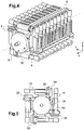
- the figure 8 shows a perspective view of the passer 34, along a mirrored axis with respect to the view of the figure 2 .
- the passer 34 comprises a motor 45 which drives a belt 46 which is connected to an attachment portion 47.
- the passer 34 has wheels 49 which are received in a rail 48 visible on the figure 2 mounted on the wall 16. Thus, the passer 34 moves along the Y axis as shown by the arrow 50.
- the main function of the passer 34 is the removal of a tube 10 from a rack 8 received on the stirrer 30, and the supply of this tube 10 to a first sampling member 51 or a second sampling member 52 ( visible on the picture 3 ).
- the passer 34 comprises a gripper 54 which is moved along the X axis by means of an actuator 56.
- the passer 34 uses a sensor 58 which reads a bar code or another optical identification means carried by the tubes 10.
- the gripper 54 could also be replaced by another gripping device, for example a vacuum nozzle, a magnetic device, etc.
- the sensor 58 could also be different, and for example be an RFID sensor.
- the passer 34 finally comprises an upper stop 60 and a lower stop 64 which limit the movement of the tube during the introduction and extraction of the needle for sampling, as well as a pusher 62.
- the pusher 62 makes it possible to carry out the ejection of a rack 8 from the agitator 30 towards the unloading shelf 6.
- the elevator 32 moves the agitator 30 to the high position at the level of the passer 34, and the motor 36 of the agitator 30 presents the carrier 8 sought in front of the passer 34. Then, the passer 34 moves along the Y axis until the tube 10 sought is identified by means of the sensor 58. Once the tube 10 has been identified, the actuator 56 moves the gripper 54 which seizes the tube 10, and the elevator 32 controls a descent of the agitator 32 in the direction Z, so that the tube 10 is extracted from the rack 8. The passer 34 is then moved in the direction Y below the first sampling member 51 or of the second sampling member 52. Once the passer 34 has stopped, the needle of the sampling member moves along the Z axis as shown by the arrows 65 to perform the sampling in the tube 10. Finally by a series of reverse operations, the tube 10 is replaced in the port ir 8 on stirrer 30.
- the passer 34 is moved furthest to the left along the Y axis according to the view of the figure 2 and 3 . Then, the elevator 32 moves the stirrer 30 to the high position at the level of the passer 34, and the motor 36 of the stirrer 30 presents the rack 8 sought in front of the passer 34. Finally, the passer 34 is moved to the right along the Y axis, the pusher 62 progressively pushing the rack 8 out of the support 38 which receives it, as far as an unloading zone 66 of the unloading shelf 6, and an actuator (not shown) moves the extracted rack 8 along the X axis as shown by the arrow 67 to extract the rack 8 from the device 1.
- scheduler which can be implemented in the form of a computer program.
- the function of the scheduler is to coordinate the loader 22, the agitator 30, the elevator 32 and the passer 34 as well as the sampling devices 51 and 52 in order to introduce the racks 8, to agitate them, and to take the samples.
- the scheduler is integrated within the housing of the device 1.
- the scheduler could be remote, and be executed from a computer or a controller located outside the housing of the device 1, and in communication with the latter in a wired or wireless way.
- a computer or controller could control a plurality of devices 1 to which it would be connected, independently of each other.
- the scheduler knows exactly which tubes are present on the racks 8, and can define a sampling and analysis sequence making it possible to optimize the rate of the device 1.
- the scheduler can "pause” the sequence in progress, and prepare the withdrawal of the urgent tube as soon as the withdrawal of the tube in progress is finished and that this one was returned to its rack.
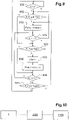
- the figure 9 represents an example function implemented by the scheduler.
- This figure represents an operation loop of the scheduler, which begins with an operation 900 in which an Ev() function tests the presence of an analysis launch event.
- a PopR() function is executed in an operation 905.
- the PopR() function receives a list Rk as an argument.
- the list Rk contains the identifiers of the racks 8 of tubes 10 currently received by the device 1.
- the racks 8 are arranged in order of priority in the list Rk, so that the first rack 8 is the one which should be given priority, etc.
- the management of the list Rk and of the introduction of the racks 8 into it can be managed by the scheduler or be automated.
- the racks 8 received on the loading shelf 4 are classified in order of proximity to the entrance of the device 1, while when an urgent rack or an urgent tube is introduced, it is placed at the head from the Rk list.
- Other methods of managing the Rk list may be used.
- the PopR() function pops the Rk list and the resulting rack identifier 8 is stored in a variable R. Then, in an operation 910, an Intro() function is executed.
- the Intro() function receives the variable R as an argument and returns a list Tub and a variable L.
- the Intro() function commands the device 1 to introduce the rack 8 whose identifier is given by the variable R, as well as to mix the tubes 10 that it carries.
- this introduction comprises the reading of labels carried by the tubes 10 making it possible to determine the identifiers of the tubes 10 concerned, as well as the analyzes which are required. Tube 10 identifiers are stored in the Tub list for later analysis. Reading the tubes 10 also makes it possible to determine the time required for the analyzes to be carried out for the rack 8 designated by the variable R, and this time is added to the variable L, which receives the estimated time to analyze all tubes loaded in device 1.
- a test compares the variable L to a threshold LT.
- the threshold LT corresponds to the estimated duration for shaking the tubes of a rack 8. Indeed, if the total duration of the remaining analyzes is less than this duration (of the order of two minutes in the example described here), it It is desirable to load a new rack, in order to shake it as quickly as possible and to ensure the operation at maximum rate of the device 1.
- operation 910 If L is less than LT, then operation 910 is repeated. Otherwise, the analysis of a tube is tested. For this, in an operation 920, a test determines whether the Tub list is empty by means of a PopT() function which receives the Tub list as an argument.
- the PopT() function determines which of the tubes should be tested next. For example, in the case of an urgent rack or an urgent tube introduced in operation 910, the Tub list can receive the identifiers of these tubes in a location such that these will be processed first as soon as they are stirred. will be completed. In this case, the Tub list is simply popped, and the identifier of the corresponding tube is returned in a variable T.
- the PopT() function can be more complex, and decide according to intrinsic and/or extrinsic algorithms the next tube to be analyzed.
- a function Shk() determines if the tube designated by the variable T has been sufficiently shaken. If not, then additional agitation is performed.
- the tube designated by the variable T is then analyzed in an operation 930 by a Proc() function.
- the Proc() function commands the device 1 to pick up the tube with identifier T on its rack, to bring it to one of the two sampling devices 51 and 52, and to put it back in its rack once once the analysis has been completed.
- the device 1 can control the reading of the labels of the tubes on the rack considered, or use an intermediate table associating each tube received in the device 1 with a given location on one side of the stirrer 30.
- the sampling unit 51 is dedicated to direct analyses, while the sampling unit 52 is dedicated to test repetitions.
- the Proc() function also updates the Tub list, either by deleting the identifier T, or by replacing it if a repeat test is necessary.
- the variable L is also updated accordingly, subtracting from it the duration of the analysis that was planned for the tube with identifier T.
- an Emp() function determines if the Tub list is empty. If not, then the loop resumes with operation 915 to determine if a new rack should be loaded. Otherwise, in an operation 940 an operation identical to operation 910 is carried out. If there are no more racks, then all the analyzes have been carried out, and device 1 resumes with the expectation of a next event in operation 900. Otherwise, the loop resumes with operation 910 to introduce this rack.
- stirrer 30 When the stirrer 30 has four rack receiving supports, one of them can be permanently left empty to serve as a buffer which is used to temporarily store a tube as needed.
- stirrer 30 can receive at least three racks 8 makes it possible to guarantee an optimum rate in the event of the need for repeating the test (also called Rerun/Reflex). Thus, even if the three racks contain only one "useful" tube, the continuity of the rate is ensured.
- the tubes before being the subject of a sample, the tubes must be subjected to sufficient agitation in order to ensure the homogeneity of the mixture in each tube. This means that when a rack is introduced into the device, the tubes must first be shaken. However, this operation requires the equivalent of 4 sampling operations. Therefore, when two racks can be accommodated, a certain continuity of cadence can be ensured by starting to agitate the tubes of the second rack while the last tubes of the first rack are being drawn.
- the rate is likely to drop, the time to properly shake these tubes.
- the third rack allows you to continue processing one or two racks, while shaking the emergency tube or the Rerun/Reflex type operating tube. Thus, these are processed as quickly as possible, while maintaining a maximum operating rate for the device.
- stirrer 30 When stirrer 30 receives 4 or more supports, new possibilities open up, such as the use of a buffer rack described above, or the possibility of leaving a support permanently empty, in order to allow the use of "urgent rack", that is to say no longer a tube, but an entire rack of tubes which will be sampled and analyzed as a priority.
- device 1 can also accommodate a second stirrer similar to stirrer 30. This allows the use of additional buffers, and lifter 32 and the passer 34 will allow the transfer from one rack to another, on the same stirrer or between the two stirrers.
- the new paradigm proposed by the invention it becomes possible to maintain a real rate of 120 samples per hour, even by using urgent tubes or by having racks with a single useful tube.
- the design of the device according to the invention opens up a new field of analysis processing, since it becomes possible to determine the fastest sampling path, independently of the composition of the racks and their order of introduction into the device 1.
- the rate could be increased, for example to 240 samples per hour or more.
- the Applicant has pushed the mechanical and functional analysis of the elements of the device in order to smooth the operation as much as possible.
- Shares a. to d. allow the simple management of interactions within a device not connected to a conveyor and not suitable for sorting tubes and/or racks.
- the scheduler is arranged to manage these actions according to an order making it possible to optimize the operating rate of the device.
- the device is capable of receiving tubes 10 and/or racks 8 of other devices 1100 within the installation. This transmission is carried out by a conveyor 1000 which brings the tubes 10 and/or racks 8 to a dedicated waiting area of the device 1.
- Shares j. and k. allow tubes and/or racks to be managed for manual sorting on output. Indeed, an operator seeing at the output a vertically offset tube and/or an offset rack will know that the latter must be the subject of separate processing, whether this be an additional analysis or a re-analysis. Of course, the dimensions of the device (length of the shelf, height of the rack outlet) must be adapted accordingly.
- the shares l. at o. allow for fully automated sorting of tubes and/or racks. Indeed, by making it possible to replace a tube in a location distinct from its original location, it becomes possible to reorganize the tubes on the fly on the various racks to take account of the tests still to be performed.
- Sorting devices whether they are dedicated to archiving or circulating tubes between several devices in the same installation, are extremely expensive, take up a lot of space, and need to be dimensioned with precision in relation to the facility.
- the sorting device becomes unsuitable, or even has to be replaced.
- the device dedicated to sorting is quite simply eliminated, because sorting is internalized. This means less cost, less space, less design time (dimensioning), and greater flexibility of scale (regardless of the size of the installation, sorting is integrated).
- the first feature is the shaker's ability to shake at least three racks simultaneously, which allows one of the three racks to be used as an adjustment destination at all times.
- the total number of "empty" slots on the racks received (that is to say the number of slots not receiving a tube), is constant, since the tubes which are moved on another rack or in a location other than their original location leave the latter empty. It stays the case as the adjustment racks are ejected as soon as they are full and they are replaced by another full rack at the entrance.
- each additional rack managed by the agitator makes it possible to manage a different adjustment destination.
- Four racks will therefore make it possible to manage two adjustment destinations, and the addition of a second stirrer will make it possible to increase the number of adjustment destinations.
- the second characteristic is a change in the management of the logic of the device. Indeed, in the case described with reference to actions a. to k., the device is completely independent of the rest of the chain, since a rack will come out as it came in, even if the tubes it contains will not necessarily be processed in their order in the rack or if another rack may be given priority. In other words, the device constitutes a closed universe not influenced by the other devices, even when it is connected to a conveyor.
- the device is a link in a chain formed by the installation.
- management by the device is influenced by the general state of the installation.
- the latter reads the information relating to each of the tubes of this rack, draws therefrom for each a destination datum, and updates the list of actions to be executed for each tube.
- the destination data indicates the next device to which a tube must be transported once processed, or archiving if there is no additional analysis.
- the destination datum is determined from the identifier of the tube by accessing a local or remote database. Alternatively, it may be part of the information read from the tube.
- no rack has destination data. It is during the sampling of the first tube that he receives that he can be assigned a destination datum. Indeed, according to the invention, when no rack has destination datum identical to that of a tube, the oldest rack is given this destination datum.
- the racks could be assigned a destination data according to the destination data of the tubes that they receive as well as the destination data of the other racks already loaded during the loading of the rack in the device.
- the arrangement of the tubes and their distribution on the racks loaded in the device are modified. For example, when a tube has been returned to a rack different from its original rack, the next tube from the original rack, if returned to the original rack, will not be returned to its original location. origin but in the location left empty by the previous tube.
- the action o. is the only one likely to impact the cadence insofar as it does not provide any analysis. However, this type of situation should be very rare in practice, and cannot be avoided.
- the user can decide to add an additional test not originally planned for a tube already in the installation.
- this tube will most likely be moved to an adjustment destination rack during one of its processes.
- all subsequent tubes will also be moved to a separate location from their original location.
- the rate will remain maximum.
- the duration of the operations has been fixed at 15 seconds, which offers a good compromise between granularity of the operations and scheduling efficiency, in particular in view of the desired rate of 120 samples per hour.
- other durations of actions could be retained, depending on the compromises and the rates sought.
- each time a rack that had been introduced empty into the device is "forced" out of the device, i.e. at the request of the user, or after exceeding a time threshold, whether to a conveyor or to a shelf, it must be replaced.
- This replacement can be manual or automated (for example via the conveyor).
- the device which has been described above is intended to carry out a certain number of analyzes after the sampling of the tubes.
- the device could be limited to sampling alone, and the analyzer could be remote.
Landscapes
- Chemical & Material Sciences (AREA)
- Health & Medical Sciences (AREA)
- Analytical Chemistry (AREA)
- General Health & Medical Sciences (AREA)
- Immunology (AREA)
- Biochemistry (AREA)
- Life Sciences & Earth Sciences (AREA)
- General Physics & Mathematics (AREA)
- Physics & Mathematics (AREA)
- Pathology (AREA)
- Chemical Kinetics & Catalysis (AREA)
- Engineering & Computer Science (AREA)
- Robotics (AREA)
- Hematology (AREA)
- Clinical Laboratory Science (AREA)
- Automatic Analysis And Handling Materials Therefor (AREA)
- Sampling And Sample Adjustment (AREA)
Claims (11)
- Vorrichtung zum Schütteln und Entnehmen biologischer Flüssigkeitsproben, umfassend eineinen Schüttler (30) von Trägereinrichtungen (8) von Röhrchen (10), ein Probenahmeorgan (51, 52), das geeignet ist, eine Entnahme einer Probe biologischer Flüssigkeiten in einem Röhrchen (10) durchzuführen, und eine Übergabeeinrichtung (34), die imstande ist, ein Röhrchen (10) an einer Trägereinrichtung (8) zu ergreifen, die in dem Schüttler (30) aufgenommen ist, und es bis zum Probenahmeorgan (51, 52) zu bewegen, dadurch gekennzeichnet, dass der Schüttler (30) imstande ist, mindestens drei Trägereinrichtungen (8) gleichzeitig zu schütteln, und dadurch, dass sie weiter einen Anweiser beinhaltet, der imstande ist, Zieldaten für ein Röhrchen (10) und Zieldaten für die Trägereinrichtung (8), die dieses Röhrchen (10) aufnimmt, zu bestimmen, und für jedes Röhrchen (10) eine endgültige Stelle in Abhängigkeit von den Zieldanten des Röhrchens (10) und den Zieldaten der Trägereinrichtungen (8) zu bestimmen, die in der Vorrichtung aufgenommen sind, wobei die endgültige Stelle eine Trägereinrichtung (8), die an dem Schüttler (30) aufgenommen ist, und eine Position in dieser Trägereinrichtung (8) bezeichnet, und anders als die Stelle des Röhrchens (10) sein kann, wenn die Trägereinrichtung (8) die es aufgenommen hat, in die Vorrichtung (1) eingeführt worden ist, und angeordnet, um die Übergabeeinrichtung (34) zu steuern, um ein Röhrchen (10) zu ergreifen, es dem Probenahmeorgan (51, 52) vorzulegen und es nach Entnahme an die endgültige Stelle zurückzustellen.
- Vorrichtung nach Anspruch 1, wobei der Anweiser angeordnet ist, um für ein gegebenes Röhrchen (10) die endgültige Stelle aus den freien Stellen an einer Trägereinrichtung (8) auszuwählen, die dieselben Zieldaten wie das gegebene Röhrchen (10) aufweist.
- Vorrichtung nach Anspruch 2, wobei der Anweiser angeordnet ist, um als endgültige Stelle an einer gegebenen Trägereinrichtung (8) die erste leere Stelle in der gegebenen Trägereinrichtung (8) zu bestimmen.
- Vorrichtung nach einem der vorstehenden Ansprüche, wobei der Anweiser angeordnet ist, um die Zieldaten, die einer gegebenen Trägereinrichtung (8) bei ihrer Einführung in die Vorrichtung (1) zugeordnet werden, auf null zu setzen.
- Vorrichtung nach einem der vorstehenden Ansprüche, wobei der Anweiser angeordnet ist, um wenn keine Trägereinrichtung (8) dieselben Zieldaten wie ein Röhrchen (10) aufweist, das von der Übergabeeinrichtung (34) ergriffen wird, die Zieldaten, die diesem Röhrchen (8) zugeordnet sind, einer Trägereinrichtung (8) zuzuteilen, der kein Zieldatum zugeordnet ist.
- Vorrichtung nach einem der vorstehenden Ansprüche, wobei der Anweiser angeordnet ist, um die Übergabeeinrichtung (34) zu steuern, um ein Röhrchen (10), das in einer Trägereinrichtung (8) aufgenommen wird, in Abhängigkeit von den Zieldaten, die diesem Röhrchen (10) zugeordnet sind, vertikal zu verschieben.
- Vorrichtung nach einem der vorstehenden Ansprüche, wobei der Anweiser angeordnet ist, um die Übergabeeinrichtung (34) zu steuern, um eine Trägereinrichtung (8) aus der Vorrichtung (1) austreten zu lassen, und um sie in einer Austrittsposition anzuordnen, die in Abhängigkeit von den Zieldaten, die der Trägereinrichtung (8) zugeordnet sind, variiert.
- Vorrichtung nach einem der vorstehenden Ansprüche, wobei der Anweiser angeordnet ist, um eine Trägereinrichtung (8), die leere Stellen aufweist, als Reaktion auf eine Nutzersteuerung oder als Reaktion auf die Überschreitung einer ausgewählten Dauer aus der Vorrichtung (1) austreten zu lassen.
- Vorrichtung nach Anspruch 7 oder 8, wobei der Anweiser angeordnet ist, um, nachdem er eine Trägereinrichtung (8), die leere Stellen aufweist, hat austreten lassen, eine Trägereinrichtung (8) in die Vorrichtung (1) eintreten zu lassen, die eine mindestens gleiche Anzahl an leeren Stellen aufweist.
- Vorrichtung nach einem der vorstehenden Ansprüche, weiter eine Zone zum Verbinden mit einem Förderer von Trägereinrichtungen (8) umfassend.
- Verfahren zum Schütteln und Entnehmen von Röhrchen, das anhand der Vorrichtung nach einem der Ansprüche 1 bis 10 ausgeführt wird, die folgenden Vorgänge umfassend:a. Einführen mindestens einer Trägereinrichtung (8), die mindestens ein Röhrchen (10) aufnimmt, das mindestens eine biologische Flüssigkeit enthält, in eine Vorrichtung (1) zum Schütteln und Entnehmen biologischer Flüssigkeitsproben,b. Bestimmen von Zieldaten für jedes Röhrchen (10) in der Vorrichtung (1) und von Zieldaten für jede Trägereinrichtung (8), die eines dieser Röhrchen (10) aufnimmt,c. Bestimmen für jedes Röhrchen (10), das in der Vorrichtung (1) aufgenommen wird, einer endgültigen Stelle in Abhängigkeit von den Zieldaten des Röhrchens (10) und den Zieldaten der Trägereinrichtungen (8), die in der Vorrichtung (1) aufgenommen werden, wobei die endgültige Stelle eine Trägereinrichtung (8) bezeichnet, die an der Vorrichtung (1) aufgenommen ist, und eine Position in dieser Trägereinrichtung (8), und anders als die Stelle des Röhrchens (10) sein kann, wenn die Trägereinrichtung (8) die es aufgenommen hat, in die Vorrichtung (1) eingeführt worden istd. Durchführen der Entnahme biologischer Flüssigkeitsproben in jedem Röhrchen (10), das in der Vorrichtung (1) aufgenommen ist,e. Platzieren des Röhrchens (10) an seiner endgültigen Stelle nach dem Vorgang d).
Applications Claiming Priority (2)
| Application Number | Priority Date | Filing Date | Title |
|---|---|---|---|
| FR1560890A FR3043782B1 (fr) | 2015-11-13 | 2015-11-13 | Dispositif d'agitation et de prelevement d'echantillons de liquides biologiques adapte pour trier |
| PCT/FR2016/052912 WO2017081411A1 (fr) | 2015-11-13 | 2016-11-09 | Dispositif d'agitation et de prélèvement d'échantillons de liquides biologiques adapté pour trier |
Publications (3)
| Publication Number | Publication Date |
|---|---|
| EP3374774A1 EP3374774A1 (de) | 2018-09-19 |
| EP3374774B1 true EP3374774B1 (de) | 2022-05-04 |
| EP3374774B8 EP3374774B8 (de) | 2022-08-31 |
Family
ID=55135371
Family Applications (1)
| Application Number | Title | Priority Date | Filing Date |
|---|---|---|---|
| EP16809975.2A Active EP3374774B8 (de) | 2015-11-13 | 2016-11-09 | Vorrichtung zum schütteln und entnehmen biologischer flüssigkeitsproben mit eignung zum sortieren |
Country Status (7)
| Country | Link |
|---|---|
| US (1) | US12005409B2 (de) |
| EP (1) | EP3374774B8 (de) |
| JP (1) | JP6824980B2 (de) |
| CN (1) | CN108603891B (de) |
| BR (1) | BR112018009541B1 (de) |
| FR (1) | FR3043782B1 (de) |
| WO (1) | WO2017081411A1 (de) |
Families Citing this family (4)
| Publication number | Priority date | Publication date | Assignee | Title |
|---|---|---|---|---|
| FR3043781B1 (fr) | 2015-11-13 | 2017-12-08 | Horiba Abx Sas | Dispositif d'agitation et de prelevement d'echantillons de liquides biologiques |
| EP3599013A1 (de) * | 2018-07-25 | 2020-01-29 | Tecan Trading Ag | Mischapparat, mischanlage und verfahren zum mischen von substanzen in geschlossenen behältern |
| CN111632872A (zh) * | 2020-06-08 | 2020-09-08 | 重庆微标惠智医疗信息技术有限公司 | 一种试管分流装置及方法 |
| JP7563195B2 (ja) * | 2021-01-25 | 2024-10-08 | 株式会社島津製作所 | 自動分析システム |
Family Cites Families (23)
| Publication number | Priority date | Publication date | Assignee | Title |
|---|---|---|---|---|
| US1980930A (en) * | 1932-03-11 | 1934-11-13 | Reyniers James Arthur | Test tube support |
| US4124122A (en) * | 1976-04-21 | 1978-11-07 | Emmitt Ronald W | Test tube rack |
| FR2692358B1 (fr) * | 1992-06-11 | 1995-08-04 | Abx Sa | Dispositif de transfert, d'agitation et de prelevement d'echantillons de produits sanguins en tubes regroupes dans des cassettes, notamment pour analyseurs hematologiques. |
| FR2730315B1 (fr) * | 1995-02-07 | 1997-03-21 | Abx Sa | Dispositif d'agitation et de prelevement d'echantillons de produits sanguins dans des tubes regroupes dans des cassettes |
| JP3032159B2 (ja) * | 1996-09-24 | 2000-04-10 | 株式会社日立製作所 | 分析システム |
| RU2318197C2 (ru) * | 2002-05-20 | 2008-02-27 | Нортроп Грумман Корпорейшен | Автоматическая система и способ обнаружения точечного источника биологического агента |
| US7501094B2 (en) * | 2003-09-15 | 2009-03-10 | Syngenta Limited | Preparation and characterization of formulations in a high throughput mode |
| US20050169733A1 (en) * | 2004-01-29 | 2005-08-04 | Drynkin Alexander V. | Automated tube handler system |
| FR2867860B1 (fr) * | 2004-03-16 | 2006-07-14 | Abx Sa | Dispositif pour l'approvisionnement d'analyseurs sur sang en tubes de sang |
| EP1655071A1 (de) | 2004-11-04 | 2006-05-10 | F. Hoffmann-La Roche Ag | Röhrchenständer mit einem beweglichen Teil zum Schütteln der Probe |
| FR2888328B1 (fr) * | 2005-07-08 | 2013-09-20 | Horiba Abx Sas | Procede automatise de preparation d'analyse d'echantillons de sang total et dispositif automatise pour sa mise en oeuvre |
| US8986665B2 (en) * | 2007-06-29 | 2015-03-24 | Johnson & Johnson Consumer Companies, Inc. | Cationic polyglyceryl compositions and compounds |
| ITUD20080128A1 (it) * | 2008-05-27 | 2009-11-28 | Alifax International S A | Unita' di caricamento ed identificazione di campioni biologici da analizzare e macchina analitica integrata per effettuare una o piu' tipologie d'analisi su piu' tipi di campione biologico differenti comprendente tale unita' di caricamento ed identif |
| IT1393352B1 (it) * | 2009-03-16 | 2012-04-20 | Inpeco Ip Ltd Ora Inpeco Holding Ltd | Apparato di aliquotazione di contenitori di materiale biologico. |
| KR102052096B1 (ko) * | 2009-05-15 | 2019-12-04 | 바이오메리욱스, 인코포레이티드. | 자동 미생물 탐지 장치 |
| AU2011320358B2 (en) * | 2010-10-29 | 2015-09-03 | Thermo Fisher Scientific Oy | Automated system for sample preparation and analysis |
| WO2013099538A1 (ja) * | 2011-12-28 | 2013-07-04 | 株式会社 日立ハイテクノロジーズ | 検体移戴装置及びシステム |
| JP6042130B2 (ja) * | 2012-07-31 | 2016-12-14 | シスメックス株式会社 | 検体移し替え装置、検体処理システムおよび検体移し替え方法 |
| US10076732B2 (en) * | 2012-11-09 | 2018-09-18 | True Health Ip Llc | Lab rack rotator and methods thereof |
| CN104204813B (zh) * | 2013-06-19 | 2016-05-25 | 深圳市亚辉龙生物科技股份有限公司 | 全自动红细胞沉降速率分析仪及其检测方法 |
| WO2016045680A1 (en) * | 2014-09-24 | 2016-03-31 | Schou Jakobsen Janus | Rotatable tube rack holder and tube rack rotator device for tube racks |
| US10764922B2 (en) * | 2015-01-08 | 2020-09-01 | Sharp Kabushiki Kaisha | Terminal device, base station device, radio communication method, and integrated circuit |
| FR3043781B1 (fr) | 2015-11-13 | 2017-12-08 | Horiba Abx Sas | Dispositif d'agitation et de prelevement d'echantillons de liquides biologiques |
-
2015
- 2015-11-13 FR FR1560890A patent/FR3043782B1/fr not_active Expired - Fee Related
-
2016
- 2016-11-09 WO PCT/FR2016/052912 patent/WO2017081411A1/fr not_active Ceased
- 2016-11-09 JP JP2018524284A patent/JP6824980B2/ja active Active
- 2016-11-09 US US15/775,245 patent/US12005409B2/en active Active
- 2016-11-09 EP EP16809975.2A patent/EP3374774B8/de active Active
- 2016-11-09 CN CN201680066834.XA patent/CN108603891B/zh active Active
- 2016-11-09 BR BR112018009541-9A patent/BR112018009541B1/pt active IP Right Grant
Also Published As
| Publication number | Publication date |
|---|---|
| CN108603891A (zh) | 2018-09-28 |
| BR112018009541B1 (pt) | 2022-07-26 |
| EP3374774A1 (de) | 2018-09-19 |
| FR3043782B1 (fr) | 2017-12-08 |
| CN108603891B (zh) | 2022-03-11 |
| US12005409B2 (en) | 2024-06-11 |
| US20180326376A1 (en) | 2018-11-15 |
| JP2018533737A (ja) | 2018-11-15 |
| FR3043782A1 (fr) | 2017-05-19 |
| BR112018009541A2 (pt) | 2018-11-06 |
| WO2017081411A1 (fr) | 2017-05-18 |
| JP6824980B2 (ja) | 2021-02-03 |
| EP3374774B8 (de) | 2022-08-31 |
Similar Documents
| Publication | Publication Date | Title |
|---|---|---|
| EP3374773B1 (de) | Vorrichtung zum schütteln und entnehmen von flüssigen proben | |
| WO2017081413A1 (fr) | Dispositif d'agitation et de prélèvement d'échantillons de liquides biologiques adapté pour trier | |
| EP1902294B1 (de) | Automatisches verfahren zur vorbereitung einer blutprobenanalyse und automatische vorrichtung dafür | |
| US9381524B2 (en) | System and method for automated sample preparation | |
| WO2017081411A1 (fr) | Dispositif d'agitation et de prélèvement d'échantillons de liquides biologiques adapté pour trier | |
| EP1913403B1 (de) | Multidisziplinärer analyseautomat zur in-vitro-diagnose | |
| CN104105969B (zh) | 离心机系统和工作流程 | |
| FR2867861A1 (fr) | Dispositif pour l'approvisionnement d'analyseurs sur sang total | |
| JP2010175513A (ja) | 検体前処理システム | |
| WO2005101024A1 (fr) | Dispositif pour l'approvisionnement d'analyseurs sur sang total en tubes de sang | |
| EP3381277A1 (de) | Verfahren und anlage zur befüllung sich bewegender eierregale | |
| CN111351952A (zh) | 一种样本分析系统及其进样方法 | |
| EP3648025A1 (de) | Steuerverfahren im sortiermodus eines pufferspeicher- und ladetaktungssystems, und entsprechende steuerungseinheit | |
| JP6683475B2 (ja) | 検体保管装置及びラック移載装置 | |
| CA3059728C (fr) | Procede de pilotage en mode flux d'un systeme de stockage tampon et de sequencement de charges, et unite de pilotage correspondante | |
| EP3903108B1 (de) | Probentransporteinheit für diagnoseautomat | |
| JP6093430B1 (ja) | 検体保管装置 | |
| EP1707275B1 (de) | Verfahren zum Bearbeiten von Postsendungen mit dynamischem Überlauf | |
| FR2957671A1 (fr) | Dispositif a prelever, peser et ranger des echantillons a analyser | |
| WO2025119525A1 (fr) | Système de manutention individuelle d'articles capable de traitement des prises multiples, et procede associe | |
| FR3167158A1 (fr) | Machine automatisée de traitement de boîtes de culture microbiologique et procédé de traitement correspondant | |
| EP4722335A1 (de) | Automatisierte maschine zur verarbeitung von mikrobiologischen kulturbehältern und entsprechendes verarbeitungsverfahren |
Legal Events
| Date | Code | Title | Description |
|---|---|---|---|
| STAA | Information on the status of an ep patent application or granted ep patent |
Free format text: STATUS: UNKNOWN |
|
| STAA | Information on the status of an ep patent application or granted ep patent |
Free format text: STATUS: THE INTERNATIONAL PUBLICATION HAS BEEN MADE |
|
| PUAI | Public reference made under article 153(3) epc to a published international application that has entered the european phase |
Free format text: ORIGINAL CODE: 0009012 |
|
| STAA | Information on the status of an ep patent application or granted ep patent |
Free format text: STATUS: REQUEST FOR EXAMINATION WAS MADE |
|
| 17P | Request for examination filed |
Effective date: 20180515 |
|
| AK | Designated contracting states |
Kind code of ref document: A1 Designated state(s): AL AT BE BG CH CY CZ DE DK EE ES FI FR GB GR HR HU IE IS IT LI LT LU LV MC MK MT NL NO PL PT RO RS SE SI SK SM TR |
|
| AX | Request for extension of the european patent |
Extension state: BA ME |
|
| DAV | Request for validation of the european patent (deleted) | ||
| DAX | Request for extension of the european patent (deleted) | ||
| GRAP | Despatch of communication of intention to grant a patent |
Free format text: ORIGINAL CODE: EPIDOSNIGR1 |
|
| STAA | Information on the status of an ep patent application or granted ep patent |
Free format text: STATUS: GRANT OF PATENT IS INTENDED |
|
| INTG | Intention to grant announced |
Effective date: 20211122 |
|
| GRAS | Grant fee paid |
Free format text: ORIGINAL CODE: EPIDOSNIGR3 |
|
| GRAA | (expected) grant |
Free format text: ORIGINAL CODE: 0009210 |
|
| STAA | Information on the status of an ep patent application or granted ep patent |
Free format text: STATUS: THE PATENT HAS BEEN GRANTED |
|
| AK | Designated contracting states |
Kind code of ref document: B1 Designated state(s): AL AT BE BG CH CY CZ DE DK EE ES FI FR GB GR HR HU IE IS IT LI LT LU LV MC MK MT NL NO PL PT RO RS SE SI SK SM TR |
|
| REG | Reference to a national code |
Ref country code: GB Ref legal event code: FG4D Free format text: NOT ENGLISH |
|
| REG | Reference to a national code |
Ref country code: CH Ref legal event code: EP |
|
| REG | Reference to a national code |
Ref country code: AT Ref legal event code: REF Ref document number: 1489587 Country of ref document: AT Kind code of ref document: T Effective date: 20220515 |
|
| REG | Reference to a national code |
Ref country code: IE Ref legal event code: FG4D Free format text: LANGUAGE OF EP DOCUMENT: FRENCH Ref country code: DE Ref legal event code: R096 Ref document number: 602016071834 Country of ref document: DE |
|
| GRAT | Correction requested after decision to grant or after decision to maintain patent in amended form |
Free format text: ORIGINAL CODE: EPIDOSNCDEC |
|
| REG | Reference to a national code |
Ref country code: CH Ref legal event code: PK Free format text: RECTIFICATION B8 |
|
| RAP4 | Party data changed (patent owner data changed or rights of a patent transferred) |
Owner name: HORIBA ABX SAS |
|
| REG | Reference to a national code |
Ref country code: LT Ref legal event code: MG9D |
|
| REG | Reference to a national code |
Ref country code: NL Ref legal event code: MP Effective date: 20220504 |
|
| REG | Reference to a national code |
Ref country code: AT Ref legal event code: MK05 Ref document number: 1489587 Country of ref document: AT Kind code of ref document: T Effective date: 20220504 |
|
| PG25 | Lapsed in a contracting state [announced via postgrant information from national office to epo] |
Ref country code: SE Free format text: LAPSE BECAUSE OF FAILURE TO SUBMIT A TRANSLATION OF THE DESCRIPTION OR TO PAY THE FEE WITHIN THE PRESCRIBED TIME-LIMIT Effective date: 20220504 Ref country code: PT Free format text: LAPSE BECAUSE OF FAILURE TO SUBMIT A TRANSLATION OF THE DESCRIPTION OR TO PAY THE FEE WITHIN THE PRESCRIBED TIME-LIMIT Effective date: 20220905 Ref country code: NO Free format text: LAPSE BECAUSE OF FAILURE TO SUBMIT A TRANSLATION OF THE DESCRIPTION OR TO PAY THE FEE WITHIN THE PRESCRIBED TIME-LIMIT Effective date: 20220804 Ref country code: NL Free format text: LAPSE BECAUSE OF FAILURE TO SUBMIT A TRANSLATION OF THE DESCRIPTION OR TO PAY THE FEE WITHIN THE PRESCRIBED TIME-LIMIT Effective date: 20220504 Ref country code: LT Free format text: LAPSE BECAUSE OF FAILURE TO SUBMIT A TRANSLATION OF THE DESCRIPTION OR TO PAY THE FEE WITHIN THE PRESCRIBED TIME-LIMIT Effective date: 20220504 Ref country code: HR Free format text: LAPSE BECAUSE OF FAILURE TO SUBMIT A TRANSLATION OF THE DESCRIPTION OR TO PAY THE FEE WITHIN THE PRESCRIBED TIME-LIMIT Effective date: 20220504 Ref country code: GR Free format text: LAPSE BECAUSE OF FAILURE TO SUBMIT A TRANSLATION OF THE DESCRIPTION OR TO PAY THE FEE WITHIN THE PRESCRIBED TIME-LIMIT Effective date: 20220805 Ref country code: FI Free format text: LAPSE BECAUSE OF FAILURE TO SUBMIT A TRANSLATION OF THE DESCRIPTION OR TO PAY THE FEE WITHIN THE PRESCRIBED TIME-LIMIT Effective date: 20220504 Ref country code: ES Free format text: LAPSE BECAUSE OF FAILURE TO SUBMIT A TRANSLATION OF THE DESCRIPTION OR TO PAY THE FEE WITHIN THE PRESCRIBED TIME-LIMIT Effective date: 20220504 Ref country code: BG Free format text: LAPSE BECAUSE OF FAILURE TO SUBMIT A TRANSLATION OF THE DESCRIPTION OR TO PAY THE FEE WITHIN THE PRESCRIBED TIME-LIMIT Effective date: 20220804 Ref country code: AT Free format text: LAPSE BECAUSE OF FAILURE TO SUBMIT A TRANSLATION OF THE DESCRIPTION OR TO PAY THE FEE WITHIN THE PRESCRIBED TIME-LIMIT Effective date: 20220504 |
|
| PG25 | Lapsed in a contracting state [announced via postgrant information from national office to epo] |
Ref country code: RS Free format text: LAPSE BECAUSE OF FAILURE TO SUBMIT A TRANSLATION OF THE DESCRIPTION OR TO PAY THE FEE WITHIN THE PRESCRIBED TIME-LIMIT Effective date: 20220504 Ref country code: PL Free format text: LAPSE BECAUSE OF FAILURE TO SUBMIT A TRANSLATION OF THE DESCRIPTION OR TO PAY THE FEE WITHIN THE PRESCRIBED TIME-LIMIT Effective date: 20220504 Ref country code: LV Free format text: LAPSE BECAUSE OF FAILURE TO SUBMIT A TRANSLATION OF THE DESCRIPTION OR TO PAY THE FEE WITHIN THE PRESCRIBED TIME-LIMIT Effective date: 20220504 Ref country code: IS Free format text: LAPSE BECAUSE OF FAILURE TO SUBMIT A TRANSLATION OF THE DESCRIPTION OR TO PAY THE FEE WITHIN THE PRESCRIBED TIME-LIMIT Effective date: 20220904 |
|
| PG25 | Lapsed in a contracting state [announced via postgrant information from national office to epo] |
Ref country code: SM Free format text: LAPSE BECAUSE OF FAILURE TO SUBMIT A TRANSLATION OF THE DESCRIPTION OR TO PAY THE FEE WITHIN THE PRESCRIBED TIME-LIMIT Effective date: 20220504 Ref country code: SK Free format text: LAPSE BECAUSE OF FAILURE TO SUBMIT A TRANSLATION OF THE DESCRIPTION OR TO PAY THE FEE WITHIN THE PRESCRIBED TIME-LIMIT Effective date: 20220504 Ref country code: RO Free format text: LAPSE BECAUSE OF FAILURE TO SUBMIT A TRANSLATION OF THE DESCRIPTION OR TO PAY THE FEE WITHIN THE PRESCRIBED TIME-LIMIT Effective date: 20220504 Ref country code: EE Free format text: LAPSE BECAUSE OF FAILURE TO SUBMIT A TRANSLATION OF THE DESCRIPTION OR TO PAY THE FEE WITHIN THE PRESCRIBED TIME-LIMIT Effective date: 20220504 Ref country code: DK Free format text: LAPSE BECAUSE OF FAILURE TO SUBMIT A TRANSLATION OF THE DESCRIPTION OR TO PAY THE FEE WITHIN THE PRESCRIBED TIME-LIMIT Effective date: 20220504 Ref country code: CZ Free format text: LAPSE BECAUSE OF FAILURE TO SUBMIT A TRANSLATION OF THE DESCRIPTION OR TO PAY THE FEE WITHIN THE PRESCRIBED TIME-LIMIT Effective date: 20220504 |
|
| REG | Reference to a national code |
Ref country code: DE Ref legal event code: R097 Ref document number: 602016071834 Country of ref document: DE |
|
| PLBE | No opposition filed within time limit |
Free format text: ORIGINAL CODE: 0009261 |
|
| STAA | Information on the status of an ep patent application or granted ep patent |
Free format text: STATUS: NO OPPOSITION FILED WITHIN TIME LIMIT |
|
| PG25 | Lapsed in a contracting state [announced via postgrant information from national office to epo] |
Ref country code: AL Free format text: LAPSE BECAUSE OF FAILURE TO SUBMIT A TRANSLATION OF THE DESCRIPTION OR TO PAY THE FEE WITHIN THE PRESCRIBED TIME-LIMIT Effective date: 20220504 |
|
| 26N | No opposition filed |
Effective date: 20230207 |
|
| PG25 | Lapsed in a contracting state [announced via postgrant information from national office to epo] |
Ref country code: SI Free format text: LAPSE BECAUSE OF FAILURE TO SUBMIT A TRANSLATION OF THE DESCRIPTION OR TO PAY THE FEE WITHIN THE PRESCRIBED TIME-LIMIT Effective date: 20220504 |
|
| PG25 | Lapsed in a contracting state [announced via postgrant information from national office to epo] |
Ref country code: MC Free format text: LAPSE BECAUSE OF FAILURE TO SUBMIT A TRANSLATION OF THE DESCRIPTION OR TO PAY THE FEE WITHIN THE PRESCRIBED TIME-LIMIT Effective date: 20220504 |
|
| REG | Reference to a national code |
Ref country code: CH Ref legal event code: PL |
|
| P01 | Opt-out of the competence of the unified patent court (upc) registered |
Effective date: 20230526 |
|
| REG | Reference to a national code |
Ref country code: BE Ref legal event code: MM Effective date: 20221130 |
|
| PG25 | Lapsed in a contracting state [announced via postgrant information from national office to epo] |
Ref country code: LI Free format text: LAPSE BECAUSE OF NON-PAYMENT OF DUE FEES Effective date: 20221130 Ref country code: CH Free format text: LAPSE BECAUSE OF NON-PAYMENT OF DUE FEES Effective date: 20221130 |
|
| PG25 | Lapsed in a contracting state [announced via postgrant information from national office to epo] |
Ref country code: LU Free format text: LAPSE BECAUSE OF NON-PAYMENT OF DUE FEES Effective date: 20221109 |
|
| PG25 | Lapsed in a contracting state [announced via postgrant information from national office to epo] |
Ref country code: IE Free format text: LAPSE BECAUSE OF NON-PAYMENT OF DUE FEES Effective date: 20221109 |
|
| PG25 | Lapsed in a contracting state [announced via postgrant information from national office to epo] |
Ref country code: BE Free format text: LAPSE BECAUSE OF NON-PAYMENT OF DUE FEES Effective date: 20221130 |
|
| PG25 | Lapsed in a contracting state [announced via postgrant information from national office to epo] |
Ref country code: IT Free format text: LAPSE BECAUSE OF FAILURE TO SUBMIT A TRANSLATION OF THE DESCRIPTION OR TO PAY THE FEE WITHIN THE PRESCRIBED TIME-LIMIT Effective date: 20220504 |
|
| PG25 | Lapsed in a contracting state [announced via postgrant information from national office to epo] |
Ref country code: HU Free format text: LAPSE BECAUSE OF FAILURE TO SUBMIT A TRANSLATION OF THE DESCRIPTION OR TO PAY THE FEE WITHIN THE PRESCRIBED TIME-LIMIT; INVALID AB INITIO Effective date: 20161109 |
|
| PG25 | Lapsed in a contracting state [announced via postgrant information from national office to epo] |
Ref country code: CY Free format text: LAPSE BECAUSE OF FAILURE TO SUBMIT A TRANSLATION OF THE DESCRIPTION OR TO PAY THE FEE WITHIN THE PRESCRIBED TIME-LIMIT Effective date: 20220504 |
|
| PG25 | Lapsed in a contracting state [announced via postgrant information from national office to epo] |
Ref country code: MK Free format text: LAPSE BECAUSE OF FAILURE TO SUBMIT A TRANSLATION OF THE DESCRIPTION OR TO PAY THE FEE WITHIN THE PRESCRIBED TIME-LIMIT Effective date: 20220504 |
|
| PG25 | Lapsed in a contracting state [announced via postgrant information from national office to epo] |
Ref country code: TR Free format text: LAPSE BECAUSE OF FAILURE TO SUBMIT A TRANSLATION OF THE DESCRIPTION OR TO PAY THE FEE WITHIN THE PRESCRIBED TIME-LIMIT Effective date: 20220504 |
|
| PG25 | Lapsed in a contracting state [announced via postgrant information from national office to epo] |
Ref country code: MT Free format text: LAPSE BECAUSE OF FAILURE TO SUBMIT A TRANSLATION OF THE DESCRIPTION OR TO PAY THE FEE WITHIN THE PRESCRIBED TIME-LIMIT Effective date: 20220504 |
|
| PG25 | Lapsed in a contracting state [announced via postgrant information from national office to epo] |
Ref country code: BG Free format text: LAPSE BECAUSE OF FAILURE TO SUBMIT A TRANSLATION OF THE DESCRIPTION OR TO PAY THE FEE WITHIN THE PRESCRIBED TIME-LIMIT Effective date: 20220504 |
|
| PG25 | Lapsed in a contracting state [announced via postgrant information from national office to epo] |
Ref country code: BG Free format text: LAPSE BECAUSE OF FAILURE TO SUBMIT A TRANSLATION OF THE DESCRIPTION OR TO PAY THE FEE WITHIN THE PRESCRIBED TIME-LIMIT Effective date: 20220504 |
|
| PGFP | Annual fee paid to national office [announced via postgrant information from national office to epo] |
Ref country code: DE Payment date: 20251118 Year of fee payment: 10 |
|
| PGFP | Annual fee paid to national office [announced via postgrant information from national office to epo] |
Ref country code: GB Payment date: 20251120 Year of fee payment: 10 |
|
| PGFP | Annual fee paid to national office [announced via postgrant information from national office to epo] |
Ref country code: FR Payment date: 20251120 Year of fee payment: 10 |