EP3373201A1 - Informationsverarbeitungsvorrichtung, informationsverarbeitungsverfahren und speichermedium - Google Patents
Informationsverarbeitungsvorrichtung, informationsverarbeitungsverfahren und speichermedium Download PDFInfo
- Publication number
- EP3373201A1 EP3373201A1 EP18160343.2A EP18160343A EP3373201A1 EP 3373201 A1 EP3373201 A1 EP 3373201A1 EP 18160343 A EP18160343 A EP 18160343A EP 3373201 A1 EP3373201 A1 EP 3373201A1
- Authority
- EP
- European Patent Office
- Prior art keywords
- image
- target
- information processing
- display
- unit
- Prior art date
- Legal status (The legal status is an assumption and is not a legal conclusion. Google has not performed a legal analysis and makes no representation as to the accuracy of the status listed.)
- Withdrawn
Links
Images







Classifications
-
- G—PHYSICS
- G06—COMPUTING OR CALCULATING; COUNTING
- G06V—IMAGE OR VIDEO RECOGNITION OR UNDERSTANDING
- G06V20/00—Scenes; Scene-specific elements
- G06V20/50—Context or environment of the image
- G06V20/52—Surveillance or monitoring of activities, e.g. for recognising suspicious objects
-
- G—PHYSICS
- G06—COMPUTING OR CALCULATING; COUNTING
- G06V—IMAGE OR VIDEO RECOGNITION OR UNDERSTANDING
- G06V40/00—Recognition of biometric, human-related or animal-related patterns in image or video data
- G06V40/10—Human or animal bodies, e.g. vehicle occupants or pedestrians; Body parts, e.g. hands
- G06V40/103—Static body considered as a whole, e.g. static pedestrian or occupant recognition
-
- G—PHYSICS
- G06—COMPUTING OR CALCULATING; COUNTING
- G06F—ELECTRIC DIGITAL DATA PROCESSING
- G06F18/00—Pattern recognition
- G06F18/20—Analysing
- G06F18/22—Matching criteria, e.g. proximity measures
-
- G—PHYSICS
- G06—COMPUTING OR CALCULATING; COUNTING
- G06T—IMAGE DATA PROCESSING OR GENERATION, IN GENERAL
- G06T11/00—Two-dimensional [2D] image generation
- G06T11/60—Creating or editing images; Combining images with text
-
- G—PHYSICS
- G06—COMPUTING OR CALCULATING; COUNTING
- G06T—IMAGE DATA PROCESSING OR GENERATION, IN GENERAL
- G06T7/00—Image analysis
- G06T7/10—Segmentation; Edge detection
- G06T7/174—Segmentation; Edge detection involving the use of two or more images
-
- G—PHYSICS
- G06—COMPUTING OR CALCULATING; COUNTING
- G06T—IMAGE DATA PROCESSING OR GENERATION, IN GENERAL
- G06T7/00—Image analysis
- G06T7/20—Analysis of motion
-
- G—PHYSICS
- G06—COMPUTING OR CALCULATING; COUNTING
- G06T—IMAGE DATA PROCESSING OR GENERATION, IN GENERAL
- G06T7/00—Image analysis
- G06T7/70—Determining position or orientation of objects or cameras
-
- G—PHYSICS
- G06—COMPUTING OR CALCULATING; COUNTING
- G06V—IMAGE OR VIDEO RECOGNITION OR UNDERSTANDING
- G06V20/00—Scenes; Scene-specific elements
- G06V20/40—Scenes; Scene-specific elements in video content
-
- G—PHYSICS
- G06—COMPUTING OR CALCULATING; COUNTING
- G06V—IMAGE OR VIDEO RECOGNITION OR UNDERSTANDING
- G06V40/00—Recognition of biometric, human-related or animal-related patterns in image or video data
- G06V40/20—Movements or behaviour, e.g. gesture recognition
-
- H—ELECTRICITY
- H04—ELECTRIC COMMUNICATION TECHNIQUE
- H04N—PICTORIAL COMMUNICATION, e.g. TELEVISION
- H04N7/00—Television systems
- H04N7/18—Closed-circuit television [CCTV] systems, i.e. systems in which the video signal is not broadcast
- H04N7/181—Closed-circuit television [CCTV] systems, i.e. systems in which the video signal is not broadcast for receiving images from a plurality of remote sources
-
- G—PHYSICS
- G06—COMPUTING OR CALCULATING; COUNTING
- G06T—IMAGE DATA PROCESSING OR GENERATION, IN GENERAL
- G06T2207/00—Indexing scheme for image analysis or image enhancement
- G06T2207/30—Subject of image; Context of image processing
- G06T2207/30196—Human being; Person
-
- G—PHYSICS
- G06—COMPUTING OR CALCULATING; COUNTING
- G06T—IMAGE DATA PROCESSING OR GENERATION, IN GENERAL
- G06T2207/00—Indexing scheme for image analysis or image enhancement
- G06T2207/30—Subject of image; Context of image processing
- G06T2207/30232—Surveillance
Definitions
- the present invention relates to an information processing apparatus for monitoring a wide region and tracking a person by using a map image, an information processing method, and a storage medium.
- the observer has to find a person to be monitored as a tracking target from the camera image. Further, if a position of a person who is assumed to be a tracking target is plotted on a map, the observer has to check the actual camera image in order to check the actual appearance or behavior of that person.
- an information processing apparatus as specified in claims 1 to 10.
- an information processing method of an information processing apparatus as specified in clams 11 and 12.
- a computer readable storage medium as specified in clam 13.
- a feature quantity of an object is analyzed from a plurality of images, and a result of collating the analysis result with a monitoring target is provided to a user based on a notice level.
- Fig. 1 is a block diagram illustrating an example of a system configuration of an image processing system.
- the image processing system includes a plurality of imaging apparatuses 101, an image analysis server apparatus 102, a data analysis server apparatus 103, a network storage apparatus 104, and an information processing apparatus 105, which are connected to each other via a local area network (LAN) 107 serving as a network line.
- LAN local area network
- the image processing system is an example of an information processing system.
- the imaging apparatuses 101 may be network cameras.
- the image analysis server apparatus 102 collects image data captured by the plurality of imaging apparatuses 101 and executes image analysis processing. For example, the image analysis server apparatus 102 extracts a feature quantity from a face region of a person through the image analysis processing.
- the data analysis server apparatus 103 collects the feature quantity extracted by the image analysis server apparatus 102 and executes data analysis processing. For example, the data analysis server apparatus 103 collates the feature quantity of persons extracted by the image analysis server apparatus 102 to execute human identification as data analysis processing.
- the images captured by the imaging apparatuses 101, the feature quantity extracted by the image analysis server apparatus 102, and the collation result of human collation acquired by the data analysis server apparatus 103 are stored in the network storage apparatus 104 via the LAN 107.
- the information processing apparatus 105 may be an apparatus such as a personal computer.
- the information processing apparatus 105 includes an input device such as a mouse, a keyboard, and/or a touch panel and a display device such as a display.
- the information processing apparatus 105 transmits the information received via the input device to the image analysis server apparatus 102 and displays the analysis result acquired by the image analysis server apparatus 102 on the display device.
- the information processing apparatus 105 superimposes the analysis result on the image data stored in the network storage apparatus 104 and displays it on the display device such as a display.
- the imaging apparatuses 101 may be configured of any number of cameras such as two or more cameras. Further, a number of image analysis server apparatuses 102, data analysis server apparatuses 103, network storage apparatuses 104, or information processing apparatuses 105 connected to the LAN 107 is not limited to the number of apparatuses in the present embodiment illustrated in Fig. 1 . A plurality of image analysis server apparatuses 102, data analysis server apparatuses 103, network storage apparatuses 104, or information processing apparatuses 105 may be connected to the LAN 107 as long as the apparatuses can be identified by the addresses.
- a PC is assumed to serve as the information processing apparatus 105.
- a physical connection mode with respect to the LAN 107 is not limited to wired connection, and any physical connection mode is possible as long as the apparatus can be connected thereto in terms of a protocol.
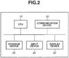
- Fig. 2 is a block diagram illustrating an example of a hardware configuration of the data analysis server apparatus 103.
- the data analysis server apparatus 103 includes a central processing unit (CPU) 10, a storage device 20, a communication device 30, an input device 40, and a display device 50 as a hardware configuration.
- the CPU 10 executes processing according to a program stored in the storage device 20.
- the storage device 20 stores a program or data used for the processing executed by the CPU 10.
- the communication device 30 connects the data analysis server apparatus 103 to the LAN 107.
- the input device 40 may be a device such as a keyboard or a mouse for inputting a user input to the CPU 10.
- the display device 50 may be a liquid crystal display for displaying a processing result of the CPU 10 to the user.
- the CPU 10 executes processing based on the program stored in the storage device 20 to realize the functional configuration (described below) of the data analysis server apparatus 103 or processing executed thereby illustrated in a flowchart.
- Each of the image analysis server apparatus 102, the network storage apparatus 104, and the information processing apparatus 105 also includes a hardware configuration similar to that of the data analysis server apparatus 103 illustrated in Fig. 2 . Then, a CPU of each apparatus executes processing based on a program stored in a storage device of the apparatus to realize a functional configuration of the apparatus and processing of the flowchart executed thereby.
- a constituent element such as the input device 40 or the display device 50 is not essential to the hardware configuration of the data analysis server apparatus 103.
- Fig. 3 is a block diagram illustrating an example of a functional configuration of each apparatus constituting the image processing system.
- the image processing system includes an image acquisition unit 201, an object detection unit 202, an image clipping unit 203, a feature extraction unit 204, a target management unit 205, a map coordinate calculation unit 206, a notice level calculation unit 207, a display switching unit 208, and an object information management unit 209.
- the image processing system further includes an input unit 210 and a display unit 211 as the functional configuration.
- the image acquisition unit 201, the object detection unit 202, the image clipping unit 203, and the feature extraction unit 204 are mounted on the image analysis server apparatus 102.
- the target management unit 205, the map coordinate calculation unit 206, the notice level calculation unit 207, and the display switching unit 208 are mounted on the data analysis server apparatus 103.
- the map coordinate calculation unit 206 and the notice level calculation unit 207 may be mounted on the image analysis server apparatus 102, and allocation of the respective functions is not limited to the example illustrated in Fig. 3 .
- the image acquisition unit 201 sequentially acquires images from the imaging apparatuses 101 at a predetermined time interval, and provides, via the LAN 107, the images, camera IDs such as internet protocol (IP) addresses associated with the respective imaging apparatuses 101, and imaging time to the object detection unit 202 and the image clipping unit 203.
- IP internet protocol
- the images acquired by the image acquisition unit 201 is not limited to the captured images acquired from the imaging apparatuses 101.
- images may be acquired by reading image data (recorded image) from the network storage apparatus 104, or may be acquired through streaming via a network.
- the object detection unit 202 executes detection processing of detecting a target from the images provided by the image acquisition unit 201.
- the object detection unit 202 collectively provides an identifier for uniquely specifying a camera ID and a detected target (hereinafter, referred to as "object ID"), a detection rectangular of the target (position and size), and detection time thereof to the image clipping unit 203 as detection information.
- the object detection unit 202 uses the imaging time provided by the image acquisition unit 201 as the detection time. For example, as a method of detecting a target from an image, the object detection unit 202 may employ a technique of detecting an entire body of a person described in " N. Dalal, B. Triggs, Histograms of Oriented Gradients for Human Detection" in IEEE Computer Society Conference on Computer Vision and Pattern Recognition (CVPR), 2005 .
- CVPR Computer Society Conference on Computer Vision and Pattern Recognition
- Fig. 4 is a diagram illustrating objects detected from the image as an example of a detection result.
- the object detection unit 202 executes detection processing on a camera image 300, so that an object ID 302 and a detection rectangular 303 are generated thereby.
- the image clipping unit 203 executes processing of creating a clipped image of a target (hereinafter, referred to as "thumbnail") from the images provided by the image acquisition unit 201 and the detection information provided by the object detection unit 202.
- the image clipping unit 203 provides the created thumbnail to the feature extraction unit 204 in association with the detection information.
- the image clipping unit 203 uses the detection rectangular included in the detection information provided by the object detection unit 202 to clip only an object region out of the image provided by the image acquisition unit 201 to create the thumbnail.
- the feature extraction unit 204 executes feature quantity extraction processing of extracting a feature quantity of the detection target from the thumbnail provided by the image clipping unit 203.
- the feature extraction unit 204 collectively provides the detection information, the thumbnail, and the feature quantity to the object information management unit 209 as object information.
- the feature extraction unit 204 may employ a technique of calculating features of an entire body described in " S. Paisitkriangkrai, Learning to rank in person re-identification with metric ensembles" in IEEE Computer Society Conference on Computer Vision and Pattern Recognition (CVPR), 2015 .
- the target management unit 205 manages information about a target, a target history, and a target candidate and provides the information to the notice level calculation unit 207 and the display switching unit 208.
- the target refers to an object specified through the input unit 210.
- the target also refers to object information of the target.
- the target history refers to a list of information about an object that has been confirmed as a target in the past.
- the target candidate refers to a list of information about an object that has been collated but has not been confirmed as a target.
- the target management unit 205 provides the held target information to the notice level calculation unit 207.
- the target management unit 205 updates the target candidate by using the object information provided by the notice level calculation unit 207.
- the target management unit 205 adds all of the object information having a collation score (described below) equal to or greater than a threshold value as the target candidates.
- the target management unit 205 confirms the target candidate that satisfies the update condition as a target, and updates the target information and the target history. For example, if time elapsed from the detection time of the target is a threshold value or more, the target management unit 205 updates the target candidate having the highest collation score as a target. Alternatively, the target management unit 205 updates the target candidate having the collation score equal to or greater than the threshold value as a target regardless of time elapsed from the detection time of the target. The target management unit 205 adds target information to the target history when the target information is updated.
- the map coordinate calculation unit 206 calculates a position of the object on the map (hereinafter, referred to as "map coordinate") by using the object information saved in the object information management unit 209, adds the map coordinate to the object information, and provides it to the object information management unit 209.
- map coordinate a position of the object on the map
- the map coordinate calculation unit 206 acquires a projection matrix of a floor face in the camera image and a floor face in the map.
- the map coordinate calculation unit 206 associates four points in the camera image and four points in the map input through the input unit 210 and acquires a homography matrix H.
- the map coordinate calculation unit 206 estimates a foot coordinate of the object in the image from a detection rectangular of the object information.
- Values fpx and fpy respectively represent values of an x-coordinate and a y-coordinate.
- Values rx, ry, rw, and rh respectively represent values of an upper-right x-coordinate, an upper-right y-coordinate, a width, and a height of the rectangular.
- the map coordinate calculation unit 206 calculates a map coordinate mp.
- Fig. 5 is a diagram illustrating an example of processing of projecting the foot coordinate to the map coordinate.
- the map coordinate calculation unit 206 inputs a floor face coordinate 401 in the camera image and a floor face coordinate 403 in the map to acquire the homography matrix and projects a foot coordinate 402 onto a map coordinate 404.
- the foot coordinate in the map can be estimated if three or more points are specified thereto instead of specifying the four points.
- the notice level calculation unit 207 uses the target information provided by the target management unit 205 and the object information saved in the object information management unit 209 to compare the feature quantities of the target and the object, and calculates a similarity as a notice level of the object.
- the notice level calculation unit 207 adds the notice level and the collation score to the object information, and provides it to the target management unit 205 and the object information management unit 209.
- the notice level calculation unit 207 compares the feature quantities to collate persons in the cameras.
- the notice level calculation unit 207 specifies the similarity of the feature quantity as the collation score.
- the collation score is high if the similarity between the objects is high, and the collation score is low if the similarity is low.
- the notice level calculation unit 207 specifies the collation score itself as the notice level.
- the notice level calculation unit 207 may employ a technique of comparing the features of an entire body described in " S. Paisitkriangkrai, Learning to rank in person re-identification with metric ensembles" in IEEE Computer Society Conference on Computer Vision and Pattern Recognition (CVPR), 2015 .
- the display switching unit 208 uses the information about a target, a target history, and a target candidate provided by the target management unit 205 and the object information saved in the object information management unit 209 to determine a display format and a display size.
- the display switching unit 208 adds the display format and the display size to the object information and provides the object information to the object information management unit 209.
- the display switching unit 208 determines a display format as the thumbnail.
- the display switching unit 208 determines a display format as the thumbnail.
- the display switching unit 208 determines a display format as the icon with respect to the object information having the notice level less than the preset threshold value. Further, with respect to all of the object information, the display switching unit 208 sets a display size to be larger if the notice level is higher, and sets the display size to be smaller if the notice level is lower.
- the processing executed by the display switching unit 208 is an example of display control processing.
- the icon is an example of a picture schematically illustrating the object.
- the object information management unit 209 saves respective pieces of object information received from the feature extraction unit 204, the map coordinate calculation unit 206, the notice level calculation unit 207, and the display switching unit 208 in an object information management table.
- Fig. 6 is a diagram illustrating an example of the object information management table.
- the object information management unit 209 can acquire a map coordinate as "(150, 120)" and a display format as "icon" by searching for the information about an object ID 3001.
- the input unit 210 generates information for specifying a person (hereinafter, referred to as "query"), searches the object information management unit 209 for the object information about the specified person, and provides that object information to the target management unit 205.
- the object ID can be used as an example of the query.
- the query is generated by the input unit 210 based on the user operation performed through the input device 40 of the information processing apparatus 105.
- the display unit 211 uses the information about the target, the target history, and the target candidate saved in the target management unit 205 and the object information acquired from the object information management unit 209, and displays an analysis result on the display device of the information processing apparatus 105 to provide the analysis result to the user.
- the display unit 211 superimposes and displays a camera icon, a person icon, a thumbnail, and moving path information of the person on preset map data.
- Fig. 7 is a diagram illustrating an example of the map data on which the camera icon and the person icon are superimposed and displayed.
- the display unit 211 acquires a camera coordinate and a camera orientation from the imaging apparatus 101 or the network storage apparatus 104 and displays a camera icon 602 at a position of the camera coordinate, so that the camera icon 602 is superimposed and displayed on map data 600.
- the display unit 211 acquires the object information indicating a detection time conforming to a rendering target time from the object information management unit 209.
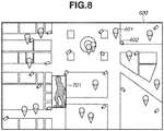
- Fig. 8 is a diagram illustrating an example of the object information in which a display format thereof is specified as a thumbnail, which is displayed by a thumbnail.
- the display unit 211 acquires a thumbnail 701 included in the object information if a display format thereof is specified as a thumbnail, and superimposes that image at a position of the map coordinate instead of an icon.
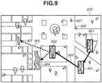
- Fig. 9 is a diagram illustrating a display example in which a moving path of a target and a past thumbnail of the target are displayed.
- the display unit 211 acquires object information corresponding to the target, the target history, and the target candidate saved in the target management unit 205 from the object information management unit 209. Then, the display unit 211 renders the object information on the map data based on the object information acquired from the object information management unit 209. At this time, the display unit 211 may change a size of the icon or the thumbnail to be rendered based on the display size of the object information.
- the display unit 211 renders the object information corresponding to a target 802 and a target history 801. The display unit 211 renders the object information corresponding to the target 802 and the target history 801 on the map data 600 even if the detection time does not coincide with the rendering target time.
- the display unit 211 arranges the target history 801 and the target 802 in the order of detection time, and renders a path line 803 between the map coordinates thereof.
- the display unit 211 renders the object information corresponding to a target candidate 804.
- the display unit 211 renders the object information corresponding to the target candidate 804 on the map data 600 even if the detection time does not coincide with the rendering target time.
- the display unit 211 further renders an auxiliary path line 805 from the target 802 to the target candidate 804.
- the display unit 211 may change a rendering size of each of the thumbnails of the target history 801, the target 802, and the target candidate 804 based on a display size of the corresponding object information.
- the display unit 211 may change a frame color of the target candidate that has not been confirmed as a target to express an unconfirmed state.
- the display unit 211 expresses a frame of the target candidate 804 with a dashed line.
- the display unit 211 may change a line color of the auxiliary path line 805 to express the unconfirmed state.
- the auxiliary path line 805 is expressed by a dashed line.
- the processing executed by the display unit 211 is also an example of display control processing.
- the object detection unit 202 extracts histograms of oriented gradients (HOG) features from the image, and uses a model in which the extracted feature quantity is learned through a support vector machine to identify whether the object is a person.
- HOG oriented gradients
- the object detection unit 202 may detect the object by using another method.
- the feature quantity to be extracted is not limited to the HOG features, and the object detection unit 202 may use Hear-Like features or local binary pattern histogram (LBPH) features, or may use a combination of the above features.
- the extracted feature quantity is shared for detecting a person.
- a model for identifying a person is not limited to the support vector machine, and the object detection unit 202 may use an adaptive boosting (AdaBoost) classifier or a randomized tree.
- AdaBoost adaptive boosting
- the object detection unit 202 outputs position coordinates of four vertexes representing a rectangular that surrounds a person in the image.
- the object detection unit 202 outputs a likelihood representing a detection result together with the position coordinates.
- the likelihood is a result of collating the extracted feature quantity with a model for identifying a person, and the likelihood represents a coincidence level with respect to the model.
- the object detection unit 202 may concurrently use a method of tracking a human body.
- a position of the person that cannot be detected by a single image is specified, so that a position of the target can be specified with high precision.
- a tracking method is not limited to the above-described method, and any method of specifying a position of the target can be used.
- the object detection unit 202 may use mean-shift tracking, Kalman filter, or on-line boosting as the tracking processing.
- the feature extraction executed by the feature extraction unit 204 is processing of extracting a feature of the target, and the processing is not limited to processing of extracting a particular feature quantity. Therefore, any processing of extracting information expressing the target can be executed.
- the feature extraction unit 204 may use, as a type of a feature quantity, a Scale-Invariant Feature Transform (SIFT) feature or a color histogram, or may combine them.
- SIFT Scale-Invariant Feature Transform
- the feature quantity is not limited to the feature of the entire body, but may be a feature quantity limited to a face region.
- the map coordinate calculation unit 206 executes processing of transforming a coordinate on an image into a coordinate on a map, and the processing is not limited to a particular transformation processing. Therefore, any processing of transforming a coordinate can be executed.
- a thumbnail saved in the object information management unit 209 may be an image or a video image of a clipped object region, and does not have to be a single clipped image. For example, when the object information is saved, the object information management unit 209 may search for information of the same object ID and combines the thumbnails of the same object information in the order of detection time to save the thumbnails as a moving image.
- Feature comparison executed by the notice level calculation unit 207 is processing of comparing the features acquired by the feature extraction unit 204, and the method is not limited to a particular comparison method.
- the notice level calculation unit 207 may use a comparison method such as an L1-distance, a Bhattacharyya distance, or an intersection method.
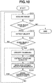
- Figs. 10 and 11 are flowcharts illustrating a flow of information processing according to the present embodiment.
- step S901 the image acquisition unit 201 acquires an image.
- step S902 the image acquisition unit 201 determines whether the image is acquired. If the image is acquired, the image acquisition unit 201 determines that the image exists (YES in step S902), and the processing proceeds to step S903. If the image cannot be acquired, the image acquisition unit 201 determines that the image does not exist (NO in step S902), and the processing of the flowchart in Fig. 10 is ended.
- step S903 the object detection unit 202 detects a plurality of objects from the image.
- step S904 the object detection unit 202 determines whether any object is detected.
- step S904 determines that the object exists (YES in step S904), and the processing proceeds to step S905. If the object cannot be detected, the object detection unit 202 determines that the object does not exist (NO in step S904), and the processing returns to step S901.
- step S905 the image clipping unit 203 creates a thumbnail.
- step S906 the feature extraction unit 204 extracts a feature quantity.
- step S907 the object information management unit 209 collectively saves the detection information, the thumbnail, and the feature quantity as the object information.
- step S908 if the object detection unit 202 determines that any unprocessed object exists (YES in step S908), the processing proceeds to step S905. If the unprocessed object does not exist (NO in step S908), the processing returns to step S901.
- step S1001 the input unit 210 inputs a query based on a user operation via the input device 40 of the information processing apparatus 105. If the query is received, in step S1002, the map coordinate calculation unit 206 calculates a map coordinate of each object. In step S1003, the notice level calculation unit 207 calculates the notice level of the object. In step S1004, the target management unit 205 updates the target, the target history, and the target candidate. In step S1005, the display switching unit 208 determines whether the notice level of the object is a threshold value or more.
- step S1005 If the display switching unit 208 determines that the notice level of the object is the threshold value or more (YES in step S1005), the processing proceeds to step S1007. If the notice level of the object is less than the threshold value (NO in step S1005), the processing proceeds to step S1006.
- step S1006 the display switching unit 208 sets a display to an icon.
- step S1007 the display switching unit 208 sets a display to a thumbnail.
- step S1008 the display switching unit 208 sets a display size of the object.
- step S1009 the display unit 211 displays the object information on the display device 50 of the information processing apparatus 105.
- step S1010 the display unit 211 displays, for example, the target, the target history, and the target candidate on the display device 50 of the information processing apparatus 105.
- step S1011 the display unit 211 determines whether to end the processing, for example, based on the user operation via the input device 40 of the information processing apparatus 105. If the display unit 211 determines that the processing is ended (YES in step S1011), the processing of the flowchart in Fig. 11 is ended. If the display unit 211 determines that the processing is not ended (NO in step S1011), the processing returns to step S1002.
- the user can check a position where the object exists and grasp the behavior of the notable object simultaneously. Therefore, a load of checking a result of image analysis can be reduced.
- Fig. 12 is a block diagram illustrating an example of a functional configuration of each of the apparatuses constituting the image processing system.
- the image processing system includes an image acquisition unit 201, an object detection unit 202, an image clipping unit 203, a map coordinate calculation unit 206, a notice level calculation unit 207, a display switching unit 208, an object information management unit 209, an input unit 210, and a display unit 211.
- the notice level calculation unit 207 calculates a notice level of each object by using the object information saved in the object information management unit 209.
- the notice level calculation unit 207 acquires the notice level of the object by using an abnormal value or a residence value in the object unit.
- the notice level calculation unit 207 recognizes the behavior of the object and acquires an abnormal value by determining the number of times of behavior defined as abnormal as the abnormal value. Alternatively, the notice level calculation unit 207 may define the abnormal level of behavior as the abnormal value. Then, the notice level calculation unit 207 determines the calculated abnormal value itself as the notice level. As a method of recognizing the behavior of the object, for example, the notice level calculation unit 207 may employ a technique of acquiring a posture of the object described in " B. X. Nie, C. Xiong, S-C. Zhu, Joint Action Recognition and Pose Estimation from Video" in IEEE Computer Society Conference on Computer Vision and Pattern Recognition (CVPR), 2015 .
- CVPR Computer Society Conference on Computer Vision and Pattern Recognition
- the residence value indicates a span of object's stopping in certain location.
- the residence value for example, is used for detecting a person who is stopping at the center of a busy corridor for a long time, because it is suspicious action.
- the notice level calculation unit 207 arranges the map coordinates having the same object ID in the order of the detection time, and assumes that the object is retained if a sum of difference values of the map coordinates in a predetermined period is a certain value or less.
- the notice level calculation unit 207 calculates the residence value to be greater if the sum of the difference values of the map coordinates is smaller. Then, the notice level calculation unit 207 determines the calculated abidance value itself as the notice level.
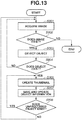
- Figs. 13 and 14 are flowcharts illustrating a flow of information processing according to the present embodiment.
- step S901 the image acquisition unit 201 acquires an image.
- step S902 the image acquisition unit 201 determines whether the image is acquired. If the image is acquired, the image acquisition unit 201 determines that the image exists (YES in step S902), and the processing proceeds to step S903. If the image cannot be acquired, the image acquisition unit 201 determines that the image does not exist (NO in step S902), and processing of the flowchart in Fig. 13 is ended.
- step S903 the object detection unit 202 detects a plurality of objects from the image.
- step S904 the object detection unit 202 determines whether any object is detected.
- step S904 determines that the object exists (YES in step S904), and the processing proceeds to step S905. If the object cannot be detected, the object detection unit 202 determines that the object does not exist (NO in step S904), and the processing returns to step S901.
- step S905 the image clipping unit 203 creates a thumbnail.
- step S907 the object information management unit 209 collectively saves the detection information, the thumbnail, and the feature quantity as the object information.
- step S908 if the object detection unit 202 determines that any unprocessed object exists (YES in step S908), the processing proceeds to step S905. If the unprocessed object does not exist (NO in step S908), the processing returns to step S901.
- step S1001 the input unit 210 inputs a query based on a user operation via the input device 40 of the information processing apparatus 105. If the query is received, in step S1002, the map coordinate calculation unit 206 calculates a map coordinate of each object. In step S1003, the notice level calculation unit 207 calculates the notice level of each object. In step S1005, the display switching unit 208 determines whether the notice level of the object is a threshold value or more. If the display switching unit 208 determines that the notice level of the object is the threshold value or more (YES in step S1005), the processing proceeds to step S1007.
- step S1006 the display switching unit 208 sets a display to an icon.
- step S1008, the display switching unit 208 sets a display size of the object.
- step S1009 the display unit 211 displays the object information on the display device 50 of the information processing apparatus 105.
- step S1011 the display unit 211 determines whether to end the processing based on the user operation via the input device 40 of the information processing apparatus 105. If the display unit 211 determines that the processing is ended (YES in step S1011), the processing of the flowchart in Fig. 14 is ended. If the display unit 211 determines that the processing should not be ended (NO in step S1011), the processing returns to step S1002.
- a moving image of the camera e.g., camera 6
- the layout is changed to a state of the display screen in Fig. 15B .
- a moving image captured by the camera 6, in which a person of the highest notice level is recognized is displayed in a size larger than the sizes of images captured by the other cameras.
- an arrangement position is changed to replace the moving image captured by the camera 1 with the moving image capture by the camera 6, so that the moving image captured by the camera 1 is displayed in a smaller size.
- a program for realizing one or more functions of the above-described embodiments is supplied to a system or an apparatus via a network or a storage medium. Then, one or more processors included in a computer of the system or the apparatus read and execute the program to realize the functions. Further, the present invention can be also realized with a circuit (e.g., application specific integrated circuit (ASIC)) that realizes the one or more functions.
- ASIC application specific integrated circuit
- the hardware configuration of the apparatus may include more than one CPU, storage device, or communication device.
- a plurality of CPUs may execute processing by using data stored in a plurality of storage devices based on a program stored in any one of the plurality of storage devices or the plurality of storage devices to realize the function of the apparatus.
- functions of the image analysis server apparatus 102, the data analysis server apparatus 103, the network storage apparatus 104, and the information processing apparatus 105 may be mounted on a single apparatus (i.e., computer).
- the CPU 10 in computer functions as elements 201-209
- the input device 40 functions as an input unit 210.
- Embodiment(s) of the present invention can also be realized by a computer of a system or apparatus that reads out and executes computer executable instructions (e.g., one or more programs) recorded on a storage medium (which may also be referred to more fully as a 'non-transitory computer-readable storage medium') to perform the functions of one or more of the above-described embodiment(s) and/or that includes one or more circuits (e.g., application specific integrated circuit (ASIC)) for performing the functions of one or more of the above-described embodiment(s), and by a method performed by the computer of the system or apparatus by, for example, reading out and executing the computer executable instructions from the storage medium to perform the functions of one or more of the above-described embodiment(s) and/or controlling the one or more circuits to perform the functions of one or more of the above-described embodiment(s).
- computer executable instructions e.g., one or more programs
- a storage medium which may also be referred to more fully as
- the computer may comprise one or more processors (e.g., central processing unit (CPU), micro processing unit (MPU)) and may include a network of separate computers or separate processors to read out and execute the computer executable instructions.
- the computer executable instructions may be provided to the computer, for example, from a network or the storage medium.
- the storage medium may include, for example, one or more of a hard disk, a random-access memory (RAM), a read only memory (ROM), a storage of distributed computing systems, an optical disk (such as a compact disc (CD), digital versatile disc (DVD), or Blu-ray Disc (BD)TM), a flash memory device, a memory card, and the like.
Landscapes
- Engineering & Computer Science (AREA)
- Theoretical Computer Science (AREA)
- Physics & Mathematics (AREA)
- General Physics & Mathematics (AREA)
- Multimedia (AREA)
- Computer Vision & Pattern Recognition (AREA)
- Data Mining & Analysis (AREA)
- Human Computer Interaction (AREA)
- Evolutionary Computation (AREA)
- Bioinformatics & Cheminformatics (AREA)
- General Engineering & Computer Science (AREA)
- Artificial Intelligence (AREA)
- Life Sciences & Earth Sciences (AREA)
- Evolutionary Biology (AREA)
- Bioinformatics & Computational Biology (AREA)
- Social Psychology (AREA)
- Psychiatry (AREA)
- General Health & Medical Sciences (AREA)
- Health & Medical Sciences (AREA)
- Signal Processing (AREA)
- Image Analysis (AREA)
- Image Processing (AREA)
- Closed-Circuit Television Systems (AREA)
- Information Retrieval, Db Structures And Fs Structures Therefor (AREA)
Applications Claiming Priority (1)
| Application Number | Priority Date | Filing Date | Title |
|---|---|---|---|
| JP2017041547A JP6961363B2 (ja) | 2017-03-06 | 2017-03-06 | 情報処理システム、情報処理方法及びプログラム |
Publications (1)
| Publication Number | Publication Date |
|---|---|
| EP3373201A1 true EP3373201A1 (de) | 2018-09-12 |
Family
ID=61581063
Family Applications (1)
| Application Number | Title | Priority Date | Filing Date |
|---|---|---|---|
| EP18160343.2A Withdrawn EP3373201A1 (de) | 2017-03-06 | 2018-03-06 | Informationsverarbeitungsvorrichtung, informationsverarbeitungsverfahren und speichermedium |
Country Status (4)
| Country | Link |
|---|---|
| US (1) | US10872242B2 (de) |
| EP (1) | EP3373201A1 (de) |
| JP (2) | JP6961363B2 (de) |
| CN (1) | CN108647557A (de) |
Cited By (1)
| Publication number | Priority date | Publication date | Assignee | Title |
|---|---|---|---|---|
| CN110796074A (zh) * | 2019-10-28 | 2020-02-14 | 桂林电子科技大学 | 一种基于时空数据融合的行人再识别方法 |
Families Citing this family (21)
| Publication number | Priority date | Publication date | Assignee | Title |
|---|---|---|---|---|
| US20180074506A1 (en) * | 2017-11-21 | 2018-03-15 | GM Global Technology Operations LLC | Systems and methods for mapping roadway-interfering objects in autonomous vehicles |
| CN110175975B (zh) * | 2018-12-14 | 2024-12-10 | 腾讯科技(深圳)有限公司 | 对象检测方法、装置、计算机可读存储介质和计算机设备 |
| JP7238902B2 (ja) * | 2018-12-27 | 2023-03-14 | 日本電気株式会社 | 情報処理装置、情報処理方法、およびプログラム |
| WO2020147792A1 (zh) * | 2019-01-16 | 2020-07-23 | 杭州海康威视数字技术股份有限公司 | 一种视频显示方法、装置、系统及摄像机 |
| JP7096176B2 (ja) * | 2019-02-01 | 2022-07-05 | 株式会社日立製作所 | 物体位置推定装置およびその方法 |
| JP7191196B2 (ja) * | 2019-02-26 | 2022-12-16 | 株式会社ソニー・インタラクティブエンタテインメント | 情報処理装置、情報処理方法、及びプログラム |
| JP7313862B2 (ja) * | 2019-03-29 | 2023-07-25 | キヤノン株式会社 | 情報処理装置、方法、及びプログラム |
| JP7389955B2 (ja) * | 2020-01-31 | 2023-12-01 | 日本電気株式会社 | 情報処理装置、情報処理方法及びプログラム |
| US20230056155A1 (en) * | 2020-01-31 | 2023-02-23 | Nec Corporation | Information processing apparatus, information processing method, and storage medium |
| JP7199593B2 (ja) * | 2020-03-03 | 2023-01-05 | 三菱電機株式会社 | 人検知装置、人検知システム、設備機器システム、人検知方法及びプログラム |
| CN111311601B (zh) * | 2020-03-26 | 2023-10-13 | 山东极视角科技股份有限公司 | 一种拼接图像的分割方法及装置 |
| JP7532075B2 (ja) | 2020-04-21 | 2024-08-13 | キヤノン株式会社 | 画像処理装置、画像処理装置の制御方法およびプログラム |
| CN112040186B (zh) * | 2020-08-28 | 2023-01-31 | 北京市商汤科技开发有限公司 | 目标对象的活动区域确定方法、装置、设备及存储介质 |
| CN113762062B (zh) * | 2021-05-27 | 2025-08-05 | 腾讯科技(深圳)有限公司 | 专注度评估方法、装置、计算机设备和存储介质 |
| CN118555989A (zh) | 2022-01-13 | 2024-08-27 | 株式会社科特拉 | 汽油发动机的排气净化用催化剂体及使用了该催化剂的排气净化系统 |
| JP2024002127A (ja) * | 2022-06-23 | 2024-01-11 | キヤノンメディカルシステムズ株式会社 | 医用情報処理装置、医用画像診断システム及びプログラム |
| US12548373B2 (en) * | 2022-08-03 | 2026-02-10 | Canon Kabushiki Kaisha | Information processing apparatus, information processing method, and storage medium that detect a position of an object in an area in which the object performs an activity, based on an obtained image |
| JP2024065688A (ja) * | 2022-10-31 | 2024-05-15 | セコム株式会社 | 監視カメラシステム及びプログラム |
| GB2626937A (en) * | 2023-02-07 | 2024-08-14 | Milestone Systems As | Video surveillance system |
| KR102710645B1 (ko) * | 2023-12-22 | 2024-09-26 | 주식회사 인텔리빅스 | 객체 썸네일 처리장치 및 그 장치의 구동방법 |
| WO2025196934A1 (ja) * | 2024-03-19 | 2025-09-25 | 日本電気株式会社 | 物標情報作成システム、物標情報作成方法及び記録媒体 |
Citations (3)
| Publication number | Priority date | Publication date | Assignee | Title |
|---|---|---|---|---|
| JPS5438861B2 (de) | 1974-07-18 | 1979-11-24 | ||
| US20150015704A1 (en) * | 2013-07-11 | 2015-01-15 | Panasonic Corporation | Tracking assistance device, a tracking assistance system and a tracking assistance method |
| US9241138B2 (en) * | 2012-02-15 | 2016-01-19 | Hitachi, Ltd. | Image monitoring apparatus, image monitoring system, and image monitoring system configuration method |
Family Cites Families (20)
| Publication number | Priority date | Publication date | Assignee | Title |
|---|---|---|---|---|
| JPS57149449A (en) | 1981-03-10 | 1982-09-16 | Toyota Motor Corp | Wear-resistant cast iron |
| US20050073585A1 (en) * | 2003-09-19 | 2005-04-07 | Alphatech, Inc. | Tracking systems and methods |
| CN100541535C (zh) * | 2004-01-06 | 2009-09-16 | 索尼株式会社 | 图像处理设备和方法 |
| US7697024B2 (en) * | 2005-11-03 | 2010-04-13 | Broadcom Corp. | Method and system of tracking and stabilizing an image transmitted using video telephony |
| JP5037279B2 (ja) * | 2007-09-19 | 2012-09-26 | 株式会社日立国際電気 | 監視装置 |
| US8195598B2 (en) * | 2007-11-16 | 2012-06-05 | Agilence, Inc. | Method of and system for hierarchical human/crowd behavior detection |
| US20100201815A1 (en) * | 2009-02-09 | 2010-08-12 | Vitamin D, Inc. | Systems and methods for video monitoring |
| JP5358851B2 (ja) * | 2009-11-12 | 2013-12-04 | 将文 萩原 | 不審行動検知方法および不審行動検知装置 |
| JP2011113255A (ja) * | 2009-11-26 | 2011-06-09 | Toyota Home Kk | 地域警備システム |
| GB2515926B (en) * | 2010-07-19 | 2015-02-11 | Ipsotek Ltd | Apparatus, system and method |
| JP5975353B2 (ja) * | 2011-03-31 | 2016-08-23 | パナソニックIpマネジメント株式会社 | 人数計測装置 |
| CN102831615A (zh) * | 2011-06-13 | 2012-12-19 | 索尼公司 | 对象监控方法和装置,以及监控系统操作方法 |
| JP6171374B2 (ja) * | 2013-02-06 | 2017-08-02 | ソニー株式会社 | 情報処理装置、情報処理方法、プログラム、及び情報処理システム |
| US9934423B2 (en) * | 2014-07-29 | 2018-04-03 | Microsoft Technology Licensing, Llc | Computerized prominent character recognition in videos |
| WO2016042946A1 (ja) * | 2014-09-19 | 2016-03-24 | シャープ株式会社 | 監視システム |
| JP5999394B2 (ja) * | 2015-02-20 | 2016-09-28 | パナソニックIpマネジメント株式会社 | 追跡支援装置、追跡支援システムおよび追跡支援方法 |
| JP6593742B2 (ja) * | 2015-04-14 | 2019-10-23 | パナソニックIpマネジメント株式会社 | 施設内人物捜索支援装置、施設内人物捜索支援システムおよび施設内人物捜索支援方法 |
| US10460587B2 (en) * | 2015-08-11 | 2019-10-29 | Sony Corporation | Information processing apparatus, information processing method, and program |
| CN106469443B (zh) * | 2015-08-13 | 2020-01-21 | 微软技术许可有限责任公司 | 机器视觉特征跟踪系统 |
| CN106096577B (zh) * | 2016-06-24 | 2019-05-31 | 安徽工业大学 | 一种摄像头分布地图中的目标追踪方法 |
-
2017
- 2017-03-06 JP JP2017041547A patent/JP6961363B2/ja active Active
-
2018
- 2018-02-28 US US15/908,632 patent/US10872242B2/en active Active
- 2018-03-06 EP EP18160343.2A patent/EP3373201A1/de not_active Withdrawn
- 2018-03-06 CN CN201810182621.4A patent/CN108647557A/zh active Pending
-
2021
- 2021-10-11 JP JP2021166671A patent/JP7282851B2/ja active Active
Patent Citations (3)
| Publication number | Priority date | Publication date | Assignee | Title |
|---|---|---|---|---|
| JPS5438861B2 (de) | 1974-07-18 | 1979-11-24 | ||
| US9241138B2 (en) * | 2012-02-15 | 2016-01-19 | Hitachi, Ltd. | Image monitoring apparatus, image monitoring system, and image monitoring system configuration method |
| US20150015704A1 (en) * | 2013-07-11 | 2015-01-15 | Panasonic Corporation | Tracking assistance device, a tracking assistance system and a tracking assistance method |
Non-Patent Citations (5)
| Title |
|---|
| AHMED DEWAN TANVIR ET AL: "Utility based decision support engine for camera view selection in multimedia surveillance systems", MULTIMEDIA TOOLS AND APPLICATIONS, KLUWER ACADEMIC PUBLISHERS, BOSTON, US, vol. 73, no. 1, 16 December 2012 (2012-12-16), pages 219 - 240, XP035396050, ISSN: 1380-7501, [retrieved on 20121216], DOI: 10.1007/S11042-012-1294-7 * |
| B. X. NIE; C. XIONG; S-C. ZHU: "Joint Action Recognition and Pose Estimation from Video", IEEE COMPUTER SOCIETY CONFERENCE ON COMPUTER VISION AND PATTERN RECOGNITION (CVPR, 2015 |
| N. DALAL; B. TRIGGS: "Histograms of Oriented Gradients for Human Detection", IEEE COMPUTER SOCIETY CONFERENCE ON COMPUTER VISION AND PATTERN RECOGNITION (CVPR, 2005 |
| S. PAISITKRIANGKRAI: "Learning to rank in person re-identification with metric ensembles", IEEE COMPUTER SOCIETY CONFERENCE ON COMPUTER VISION AND PATTERN RECOGNITION (CVPR, 2015 |
| S. YU; Y. YANG; A. HAUPTMANN: "Harry Potter's Marauder's Map: Localizing and Tracking Multiple Persons-of-Interest by Nonnegative Discretization", IEEE COMPUTER SOCIETY CONFERENCE ON COMPUTER VISION AND PATTERN RECOGNITION (CVPR, 2013 |
Cited By (1)
| Publication number | Priority date | Publication date | Assignee | Title |
|---|---|---|---|---|
| CN110796074A (zh) * | 2019-10-28 | 2020-02-14 | 桂林电子科技大学 | 一种基于时空数据融合的行人再识别方法 |
Also Published As
| Publication number | Publication date |
|---|---|
| JP7282851B2 (ja) | 2023-05-29 |
| CN108647557A (zh) | 2018-10-12 |
| JP2022003831A (ja) | 2022-01-11 |
| US20180253603A1 (en) | 2018-09-06 |
| US10872242B2 (en) | 2020-12-22 |
| JP6961363B2 (ja) | 2021-11-05 |
| JP2018148399A (ja) | 2018-09-20 |
Similar Documents
| Publication | Publication Date | Title |
|---|---|---|
| US10872242B2 (en) | Information processing apparatus, information processing method, and storage medium | |
| AU2022252799B2 (en) | System and method for appearance search | |
| Siebel et al. | Fusion of multiple tracking algorithms for robust people tracking | |
| US9934423B2 (en) | Computerized prominent character recognition in videos | |
| US10795928B2 (en) | Image search apparatus, system, and method | |
| TWI438702B (zh) | 影像環境邊界之動態設定方法及人員活動內容之即時判定方法 | |
| Juang et al. | Fall down detection under smart home system | |
| EP3324307B1 (de) | Abfragevorrichtung, abfrageverfahren und computerlesbares medium | |
| JP2014155159A (ja) | 情報処理システム、情報処理方法及びプログラム | |
| CN110008795A (zh) | 图像目标追踪方法及其系统与计算机可读取存储介质 | |
| CN110490171B (zh) | 一种危险姿态识别方法、装置、计算机设备及存储介质 | |
| WO2019033567A1 (zh) | 眼球动作捕捉方法、装置及存储介质 | |
| US12430777B2 (en) | Image processing apparatus, image processing method, and non-transitory computer-readable storage medium to perform a tracking process, using a tracking model | |
| JP2013206458A (ja) | 画像における外観及びコンテキストに基づく物体分類 | |
| KR102036490B1 (ko) | 소스 비디오 내에서 관심 동영상을 추출하는 장치 및 방법 | |
| JP2015011526A (ja) | 行動認識装置、方法及びプログラム並びに認識器構築装置 | |
| JP6384167B2 (ja) | 移動体追跡装置及び移動体追跡方法、並びにコンピュータ・プログラム | |
| WO2016006090A1 (ja) | 電子機器、方法及びプログラム | |
| JP7374632B2 (ja) | 情報処理装置、情報処理方法及びプログラム | |
| JPWO2018179119A1 (ja) | 映像解析装置、映像解析方法およびプログラム | |
| JP2018006910A (ja) | 撮像装置、撮像装置の制御方法およびプログラム | |
| Yonetani et al. | Ego-surfing: Person localization in first-person videos using ego-motion signatures | |
| WO2022038702A1 (en) | Causal interaction detection apparatus, control method, and computer-readable storage medium | |
| JP2018190132A (ja) | 画像認識用コンピュータプログラム、画像認識装置及び画像認識方法 | |
| JP2016207106A (ja) | 物体検出における誤検出低減方法および装置 |
Legal Events
| Date | Code | Title | Description |
|---|---|---|---|
| PUAI | Public reference made under article 153(3) epc to a published international application that has entered the european phase |
Free format text: ORIGINAL CODE: 0009012 |
|
| STAA | Information on the status of an ep patent application or granted ep patent |
Free format text: STATUS: THE APPLICATION HAS BEEN PUBLISHED |
|
| AK | Designated contracting states |
Kind code of ref document: A1 Designated state(s): AL AT BE BG CH CY CZ DE DK EE ES FI FR GB GR HR HU IE IS IT LI LT LU LV MC MK MT NL NO PL PT RO RS SE SI SK SM TR |
|
| AX | Request for extension of the european patent |
Extension state: BA ME |
|
| STAA | Information on the status of an ep patent application or granted ep patent |
Free format text: STATUS: REQUEST FOR EXAMINATION WAS MADE |
|
| 17P | Request for examination filed |
Effective date: 20190312 |
|
| RBV | Designated contracting states (corrected) |
Designated state(s): AL AT BE BG CH CY CZ DE DK EE ES FI FR GB GR HR HU IE IS IT LI LT LU LV MC MK MT NL NO PL PT RO RS SE SI SK SM TR |
|
| STAA | Information on the status of an ep patent application or granted ep patent |
Free format text: STATUS: EXAMINATION IS IN PROGRESS |
|
| 17Q | First examination report despatched |
Effective date: 20210407 |
|
| STAA | Information on the status of an ep patent application or granted ep patent |
Free format text: STATUS: THE APPLICATION HAS BEEN WITHDRAWN |
|
| 18W | Application withdrawn |
Effective date: 20240109 |