EP3372984A1 - Messinstrument für gasgetragenen feinstaub und vorrichtung für saubere umwelt - Google Patents
Messinstrument für gasgetragenen feinstaub und vorrichtung für saubere umwelt Download PDFInfo
- Publication number
- EP3372984A1 EP3372984A1 EP16881643.7A EP16881643A EP3372984A1 EP 3372984 A1 EP3372984 A1 EP 3372984A1 EP 16881643 A EP16881643 A EP 16881643A EP 3372984 A1 EP3372984 A1 EP 3372984A1
- Authority
- EP
- European Patent Office
- Prior art keywords
- gas
- unit
- chamber
- pump
- flow rate
- Prior art date
- Legal status (The legal status is an assumption and is not a legal conclusion. Google has not performed a legal analysis and makes no representation as to the accuracy of the status listed.)
- Granted
Links
Images

Classifications
-
- G—PHYSICS
- G01—MEASURING; TESTING
- G01N—INVESTIGATING OR ANALYSING MATERIALS BY DETERMINING THEIR CHEMICAL OR PHYSICAL PROPERTIES
- G01N1/00—Sampling; Preparing specimens for investigation
- G01N1/02—Devices for withdrawing samples
- G01N1/22—Devices for withdrawing samples in the gaseous state
- G01N1/2226—Sampling from a closed space, e.g. food package, head space
-
- C—CHEMISTRY; METALLURGY
- C12—BIOCHEMISTRY; BEER; SPIRITS; WINE; VINEGAR; MICROBIOLOGY; ENZYMOLOGY; MUTATION OR GENETIC ENGINEERING
- C12M—APPARATUS FOR ENZYMOLOGY OR MICROBIOLOGY; APPARATUS FOR CULTURING MICROORGANISMS FOR PRODUCING BIOMASS, FOR GROWING CELLS OR FOR OBTAINING FERMENTATION OR METABOLIC PRODUCTS, i.e. BIOREACTORS OR FERMENTERS
- C12M39/00—Means for cleaning the apparatus or avoiding unwanted deposits of microorganisms
-
- C—CHEMISTRY; METALLURGY
- C12—BIOCHEMISTRY; BEER; SPIRITS; WINE; VINEGAR; MICROBIOLOGY; ENZYMOLOGY; MUTATION OR GENETIC ENGINEERING
- C12M—APPARATUS FOR ENZYMOLOGY OR MICROBIOLOGY; APPARATUS FOR CULTURING MICROORGANISMS FOR PRODUCING BIOMASS, FOR GROWING CELLS OR FOR OBTAINING FERMENTATION OR METABOLIC PRODUCTS, i.e. BIOREACTORS OR FERMENTERS
- C12M41/00—Means for regulation, monitoring, measurement or control, e.g. flow regulation
- C12M41/06—Means for regulation, monitoring, measurement or control, e.g. flow regulation of illumination
-
- C—CHEMISTRY; METALLURGY
- C12—BIOCHEMISTRY; BEER; SPIRITS; WINE; VINEGAR; MICROBIOLOGY; ENZYMOLOGY; MUTATION OR GENETIC ENGINEERING
- C12M—APPARATUS FOR ENZYMOLOGY OR MICROBIOLOGY; APPARATUS FOR CULTURING MICROORGANISMS FOR PRODUCING BIOMASS, FOR GROWING CELLS OR FOR OBTAINING FERMENTATION OR METABOLIC PRODUCTS, i.e. BIOREACTORS OR FERMENTERS
- C12M41/00—Means for regulation, monitoring, measurement or control, e.g. flow regulation
- C12M41/12—Means for regulation, monitoring, measurement or control, e.g. flow regulation of temperature
- C12M41/14—Incubators; Climatic chambers
-
- G—PHYSICS
- G01—MEASURING; TESTING
- G01N—INVESTIGATING OR ANALYSING MATERIALS BY DETERMINING THEIR CHEMICAL OR PHYSICAL PROPERTIES
- G01N1/00—Sampling; Preparing specimens for investigation
- G01N1/02—Devices for withdrawing samples
-
- G—PHYSICS
- G01—MEASURING; TESTING
- G01N—INVESTIGATING OR ANALYSING MATERIALS BY DETERMINING THEIR CHEMICAL OR PHYSICAL PROPERTIES
- G01N1/00—Sampling; Preparing specimens for investigation
- G01N1/02—Devices for withdrawing samples
- G01N1/22—Devices for withdrawing samples in the gaseous state
-
- G—PHYSICS
- G01—MEASURING; TESTING
- G01N—INVESTIGATING OR ANALYSING MATERIALS BY DETERMINING THEIR CHEMICAL OR PHYSICAL PROPERTIES
- G01N1/00—Sampling; Preparing specimens for investigation
- G01N1/28—Preparing specimens for investigation including physical details of (bio-)chemical methods covered elsewhere, e.g. G01N33/50, C12Q
- G01N1/34—Purifying; Cleaning
-
- G—PHYSICS
- G01—MEASURING; TESTING
- G01N—INVESTIGATING OR ANALYSING MATERIALS BY DETERMINING THEIR CHEMICAL OR PHYSICAL PROPERTIES
- G01N1/00—Sampling; Preparing specimens for investigation
- G01N1/28—Preparing specimens for investigation including physical details of (bio-)chemical methods covered elsewhere, e.g. G01N33/50, C12Q
- G01N1/44—Sample treatment involving radiation, e.g. heat
-
- G—PHYSICS
- G01—MEASURING; TESTING
- G01N—INVESTIGATING OR ANALYSING MATERIALS BY DETERMINING THEIR CHEMICAL OR PHYSICAL PROPERTIES
- G01N1/00—Sampling; Preparing specimens for investigation
- G01N1/02—Devices for withdrawing samples
- G01N1/22—Devices for withdrawing samples in the gaseous state
- G01N1/24—Suction devices
-
- G—PHYSICS
- G01—MEASURING; TESTING
- G01N—INVESTIGATING OR ANALYSING MATERIALS BY DETERMINING THEIR CHEMICAL OR PHYSICAL PROPERTIES
- G01N15/00—Investigating characteristics of particles; Investigating permeability, pore-volume or surface-area of porous materials
- G01N15/06—Investigating concentration of particle suspensions
-
- G—PHYSICS
- G01—MEASURING; TESTING
- G01N—INVESTIGATING OR ANALYSING MATERIALS BY DETERMINING THEIR CHEMICAL OR PHYSICAL PROPERTIES
- G01N15/00—Investigating characteristics of particles; Investigating permeability, pore-volume or surface-area of porous materials
- G01N2015/0042—Investigating dispersion of solids
- G01N2015/0046—Investigating dispersion of solids in gas, e.g. smoke
Definitions
- the present disclosure relates to an air particle measurement apparatus and clean environment equipment.
- a particle measurement apparatus or a particle counter is used for measuring particles in working environment, as an indicator of cleanliness (for example, Patent Literature 1).
- Such a particle measurement apparatus is usually used for measuring particles in the air in an ordinary state (temperature, humidity).
- a common particle measurement apparatus may not be able to accurately measure the particles, due to condensation of the moisture particles in the air or condensation in a sampling tube.
- An embodiment of the present disclosure to solve such a problem is an air particle measurement apparatus connected to a chamber, the chamber temporarily or constantly maintained at a humidity higher than an outside air humidity, the air particle measurement apparatus comprising: a measurement unit configured to measure particles in the drawn gas; a suction pipe through which the gas drawn from an interior of the chamber is transported to the measurement unit, the suction pipe connecting a mounting unit of the chamber and the measurement unit; a pump configured to suction the gas so as to be transported from the chamber to the measurement unit through the suction pipe; and a heating unit configured to heat the gas in a path upstream from the measurement unit.
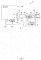
- FIG. 1 is a diagram schematically illustrating the clean environment equipment 1 according to the first embodiment.
- the clean environment equipment 1 includes: a chamber 110; a supply unit 128 configured to supply water vapor or mist-like moisture to increase the humidity in the chamber 110; and an air particle measurement apparatus 120 connected to the chamber 110.
- the chamber 110 is, for example, an isolator or an incubator, and provides a closed work space in which work on a biological sample (e.g., cell culture) is performed.
- a biological sample e.g., cell culture
- water vapor or mist-like moisture is supplied to the chamber 110 by the supply unit 128.
- the supply unit 128 is controlled by a control unit 113 of the clean environment equipment 1.
- the water vapor or mist-like moisture includes particles obtained, using a sprayer, by spraying humidifying water, sterilizing gas, and sterile liquid, which are used to humidify or sterilize the interior of the chamber 110.
- the moisture includes not only water but also aqueous solution.
- the interior of the chamber 110 is temporarily or constantly maintained at a humidity higher than the outside air humidity by the supply unit 128.
- the supply unit 128 is configured to supply sterilizing gas obtained by vaporizing sterile liquid. Then, in a sterilizing process, it is necessary to condense the sterilizing gas on the inner wall, and thus the internal humidity temporarily reaches about 100%.
- the supply unit 128 is a water storage portion disposed in the interior to store humidifying water. The water storage portion is heated by a heater such that the internal humidity is constantly maintained at about 95%.
- the technique according to the present disclose is particularly effective, however, it is effective at least in equipment in which the humidity is temporarily or constantly maintained greater than the outside air humidity.
- the particles in the gas is measured by the air particle measurement apparatus 120 so that the particles contained in the gas within the work space do not exceed the predetermined value.
- the chamber 110 includes a mounting unit 111 to connect a suction pipe 124, and a mounting unit 112 to connect a discharge pipe 125.
- the air particle measurement apparatus 120 includes, as illustrated in FIG. 1 , a measurement unit 121, a pump 122, a control unit 123, the suction pipe 124, the discharge pipe 125, a heater 126, and a removal unit 127.
- the measurement unit 121, the pump 122, and the control unit 123 are stored in a housing 129.
- the suction pipe 124, the discharge pipe 125, the heater 126, and the removal unit 127 may be components attached to the chamber 110.
- the measurement unit 121 is configured to measure the particles in the drawn gas.
- the measurement unit 121 is, for example, a light scattering sensor, and is configured to detect particles by irradiating the particles drawn in the measurement unit 121 with laser light and capturing the scattering of the light using the sensor.
- the gas inlet port of the measurement unit 121 is provided with a flowmeter 121a.
- the flowmeter 121a is configured to measure the flow rate of the gas drawn into the measurement unit 121, and output a measurement signal to the control unit 123. Such a measurement signal is used for the control unit 123 to control the suction amount of the pump 122.
- the flowmeter 121a may be provided downstream from the measurement unit 121.
- the suction pipe 124 connects the mounting unit 111 of the chamber 110 and the measurement unit 121, and the gas drawn from the interior of the chamber 110 is transported to the measurement unit 121.
- the pump 122 is, for example, a diaphragm pump or a rotary pump, and is configured to draw the gas to be transported from the chamber 110 through the suction pipe 124 to the measurement unit 121.
- the pump 122 is connected to the measurement unit 121 on the downstream side, but may be connected to the measurement unit 121 on the upstream side. Note that the operation of the pump 122 will be described later in connection with the control unit 123.
- the discharge pipe 125 connects the pump 122 and the mounting unit 112 of the chamber 110, and transports the gas discharged from the pump 122 to the chamber 110.
- the gas within the chamber 110 is drawn out from the mounting unit 111, and is returned into the chamber 110 from the mounting unit 112, through the suction pipe 124, the measurement unit 121, the pump 122, and the discharge pipe 125. That is, the suction pipe 124, the measurement unit 121, the pump 122, and the discharge pipe 125 form a path through which the gas flows.
- the heater 126 is an example of a heating unit, and is configured to heat the gas in the path upstream from the measurement unit 121.
- the heater 126 has a structure to substantially completely cover the suction pipe 124.
- the heater 126 may have a structure to partially cover the suction pipe 124.
- the temperature of the heater 126 is controlled by the control unit 123.
- a temperature sensor (not shown) to measure the temperature of the gas is provided in the path downstream from the heater 126.
- the control unit 123 controls the temperature of the heater 126 based on the temperature of the gas measured by the temperature sensor and the preset temperature.
- the preset temperature is, for example, 100°C or may be set by a user.
- the removal unit 127 is provided upstream from a heating unit 126, and is configured to remove the moisture in the gas by condensing the moisture in the gas in the suction pipe 124.
- the removal unit 127 is provided in the path between the mounting unit 111 and the heater 126.
- the removal unit 127 may be constituted by, for example, a branch pipe 124a branched vertically downward from a position A in the suction pipe 124, and a container to receive water droplets dripping from the lower end of the branch pipe 124a.
- a branch pipe 124a branched vertically downward from a position A in the suction pipe 124
- a container to receive water droplets dripping from the lower end of the branch pipe 124a For example, assuming that the temperature within the chamber 110 is 37°C, and the temperature of the outside air is 25°C, the gas within the chamber 110 having a high humidity is cooled to condense in the suction pipe 124. Such moisture generated as a result of condensation drops from the branch pipe 124a to the container to be stored, while the gas with reduced moisture flows toward the heater 126.
- the removal unit 127 may be a condenser to condense moisture in the gas by heat exchange of the gas in the path with cooling water.
- the control unit 123 is configured to control driving of the pump 122 so as to adjust the flow rate of the gas drawn into the measurement unit 121.
- the control unit 123 controls the pump 126 so that the flow rate of the gas drawn in the measurement unit 121 when the heater 126 is operating to generate a first amount of heat is greater than the flow rate when the heater 126 is operating to generate a second amount of heat smaller than the first amount of heat or the flow rate when the heater 126 is stopped.
- the control unit 123 may be independent of the control unit 113 of the clean environment equipment 1, or may be in cooperation therewith. Further, the control unit 123 and the control unit 113 may be integrated.
- the amount of suction of the pump 122 is adjusted based on a gas state equation.
- control unit 123 can monitor the operational status of the supply unit 128, and the control unit 123 can also control the suction amount of the pump 122 according to the operation of the supply unit 128.
- the pump 122 may be driven such that the flow rate of the gas drawn into the measurement unit 121 when water vapor or mist-like moisture is being supplied from the supply unit 128 becomes smaller than the flaw rate of the gas when water vapor or mist-like moisture is not supplied from the supply unit 128.
- the control unit 123 may stop the pump 122 when humidifying water and/or sterile liquid is sprayed or sterilizing gas is supplied from the supply unit 128.
- suction of the gas by the pump 122 may be stopped.
- the control unit 123 may control the amount of suction of the pump 122 according to signals from the control unit 113 that controls the operation of the supply unit 128.
- the control unit 123 has a measurement mode and a reset mode (aeration mode).
- the measurement mode corresponding to a first mode is a mode of driving the pump 122 so that the flow rate of the gas drawn into the measurement unit 121 becomes a predetermined flow rate (first flow rate) corresponding to the temperature of the heater 126, so as to perform measurement with the measurement unit 121.
- the reset mode corresponding to a second mode is a mode of driving the pump 122 so that the gas at a flow rate (second flow rate) greater than the gas flow rate in the measurement mode flows into the measurement unit 121, so as to return the measurement unit 121 to its initial state.
- the reset mode is executed, for example, once a day. Alternatively, the reset mode may be executed to quickly remove the humidifying water, sterile liquid, sterilizing gas from the path of the gas after humidification or sterilization in the chamber 110.
- the operation of the clean environment equipment 1 including the above-described configuration will be described.
- the operation of the clean environment equipment 1 is broadly classified into the operation when measuring the particles in the gas, the operation when the measurement unit 121 is reset to its initial state, and the operation when the interior of the chamber 110 is sterilized, and will be described below in sequence.
- the gas in the chamber 110 is drawn by the pump 122 through the suction pipe 124 into the measurement unit 121, and the particles therein are measured at the measurement unit 121.
- the gas having a high humidity drawn from the chamber 110 is heated to the desired temperature by the heater 126 while the moisture thereof is removed in the removal unit 127. Accordingly, the humidity of the gas after being heated is reduced to become lower than the humidity of the gas before being heated.
- control unit 123 calculates the expansion of the gas caused by heating, based on the above described Expression 1, to control the suction amount of the pump 122 based on such a calculation result. Accordingly, the measurement unit 121 can obtain the measurement result corresponding to the number of the particles in the predetermined volume of the gas at the predetermined temperature (e.g., 25°C), even when the gas is heated by the heater 126.
- the predetermined temperature e.g. 25°C
- the control unit 123 controls the pump 122 so that the suction amount of the pump 122 becomes greater than the above-described suction amount of the pump 122 when the particles are measured.
- the heater 126 heats the gas in the path to the predetermined temperature.
- the gas having a high temperature and a humidity lowered by being heated flows into the measurement unit 121, and this dries the interior of the measurement unit 121. Accordingly, reliability of measurement by the measurement unit 121 is ensured.
- the interior of the chamber 110 is periodically humidified and/or sterilized, to prevent contamination in the interior of the chamber 110 or similar.
- the interior of the chamber 110 is humidified and/or sterilized such that sterilizing gas is supplied from the supply unit 128 into the chamber 110, or humidifying water and/or sterile liquid is sprayed from the supply unit 128 into the chamber 110.
- the control unit 123 stops the suction of the gas by the pump 122 so as to reliably perform humidification and/or sterilization.
- control unit 123 may perform control so that the pump 122 sucks the amount of the gas that is greater than the amount of the gas when measurement is performed, similarly to the case of the above described resetting time.
- the heater 126 is described as having a structure of covering the suction pipe 124, but it is not limited thereto. It is further preferable to heat the entire flow path.
- the heater 126 does not only cover the suction pipe 124, but also completely or partially cover the discharge pipe 125.
- Heating not only a part of the flow path but the entire flow path can further suppress condensation in a pipe, such as the suction pipe 124 and the discharge pipe 125.
- the gas is returned to the chamber 110 through a flow path on the discharge side, e.g., the discharge pipe 125.
- a flow path on the discharge side e.g., the discharge pipe 125.
- water particles may be returned into the chamber 110. Accordingly, it is desirable to retain warmth of the discharge flow path such as the discharge pipe 125.
- a pipe such as the suction pipe 124 and the discharge pipe 125 is heated by the heater 126, it is more preferable not to heat the pipe at a temperature higher than about 40°C.
- FIG. 2 is a diagram schematically illustrating the clean environment equipment 2 according to the second embodiment.
- the same reference numerals are given to components similar to those in the clean environment equipment 1.
- the clean environment equipment 2 includes, similarly to the clean environment equipment 1 in the first embodiment, a chamber 210, a supply unit 228, and an air particle measurement apparatus 220. However, a component corresponding to the removal unit 127 in the first embodiment is not included.
- a heater 226 included in the air particle measurement apparatus 220 partially covers the outside of a housing 229 in a suction pipe 224.
- a section covered with the heater 226 in the suction pipe 224 is shorter than the suction pipe 124 in the first embodiment. Accordingly, the heater 226 enables sufficient heating even in the short interval, for example, by heating the gas at a temperature higher than the temperature as in the heater 126 of the first embodiment, and/or increasing the surface area such that the pipe is wound or rolled inside the heater 226.
- Such an operation of the clean environment equipment 2 according to the second embodiment is, similarly to the first embodiment, broadly classified into the operation when measuring the particles in the gas, the operation when a measurement unit 221 is reset to its initial state, and the operation when the interior of the chamber 210 is humidified and/or sterilized. The details of these operations are omitted.
- At least one of the suction pipe 224 and a discharge pipe 225 may be constituted by a hygroscopic resin film.
- the hygroscopic resin film includes, for example, Nafion tubing which is a widely known member. Although the details are omitted, the Nafion tubing has such a function of removing moisture by discharging the moisture from the inside to the outside of the tube.
- Nafion tubing has such a function of removing moisture by discharging the moisture from the inside to the outside of the tube.
- NAFION is a registered trademark.
- such a Nafion tube may be used for the whole or a part of the suction pipe 224. That is, the Nafion tube may be provided in the path between a mounting unit 211 and the heater 226.
- the Nafion tube may be used for the whole or a part of the discharge pipe 225. That is, the Nafion tube may be provided in the path between a mounting unit 212 and a pump 222.
- the moisture can be removed with the Nafion tube, it is possible to have a configuration without the heater 226, so that an apparatus will have a simple configuration.
- the case where the moisture can be sufficiently removed indicates the case where the moisture can be removed to such a degree that the measurement unit 221 is not affected by the moisture in the gas in terms of the accuracy with which the particles in target gas is measured.
- FIG. 3 is a diagram schematically illustrating the clean environment equipment according to the third embodiment.
- the same reference numerals are given to components similar to those in the clean environment equipment 1.
- the clean environment equipment 3 includes a chamber 310, a supply unit 328, and an air particle measurement apparatus 320.
- a component corresponding to the removal unit 127 in the first embodiment is not included.
- a heater 326 is mounted to a mounting unit 331 of the chamber 310, and heats the gas flowing through a mounting unit 311 and a suction pipe 324 (connecting portion) .
- the heater 326 enables sufficient heating, for example, by heating the gas at a temperature higher than the temperature as in the heater 126 of the first embodiment, and/or increasing the surface area such that the pipe is wound or rolled inside the heater 326, similarly to the heater 226 in the second embodiment.
- Such an operation of the clean environment equipment 3 according to a third embodiment is broadly classified into the operation when measuring the particles in the gas, the operation when a measurement unit 321 is reset to its initial state, and the operation when the interior of a chamber 310 is humidified and/or sterilized, similarly to the first embodiment. The details of these operations are omitted.
- the air particle measurement apparatus 120 which is connected to the chamber 110 (210, 310), the chamber 110 (210, 310) temporarily or constantly maintained at a humidity higher than the outside air humidity, comprises: the measurement unit 121 (221, 321) configured to measure particles in drawn gas; the suction pipe 124 (224, 324) through which the gas drawn from the interior of the chamber 110 (210, 310) is transported to the measurement unit 121 (221, 321), the suction pipe connecting the mounting unit 111 (211, 311) of the chamber 110 (210, 310) and the measurement unit 121 (221, 321); the pump 122 (222, 322) configured to suction the gas so as to be transported from the chamber 110 (210, 310) to the measurement unit 121 (221, 321) through the suction pipe 124 (224, 324); and the heating unit 126 226, 326) configured to heat the gas in the path upstream from the measurement unit 121 (221, 321).
- the gas having a high humidity drawn from the chamber 110 is heated by the heater 126 (226, 326), and the humidity in the gas after being heated is lowered.
- This can prevent the gas from condensing in the suction pipe 124 (224, 324) and the measurement unit 121 (221, 321). Accordingly, it is possible to provide the air particle measurement apparatus capable of accurately measuring particles even when measuring the particles in the gas having a high humidity.
- the heating unit 126 (226, 326) has a structure to cover the suction pipe 124 (224, 324), it is possible to efficiently heat the gas flowing through the suction pipe 124 (224, 324).
- control unit 123 configured to drive the pump 122 (222, 322) so that the flow rate of the gas drawn into the measurement unit 121 (221, 321) when the heating unit 126 (226, 326) is operating to generate the first amount of heat becomes greater than the flow rate when the heating unit 126 (226, 326) is operating to generate the second amount of heat that is smaller than the first amount of heat or the flow rate when the heating unit 126 (226, 326) is stopped.
- the control unit 123 223, 323 configured to drive the pump 122 (222, 322) so that the flow rate of the gas drawn into the measurement unit 121 (221, 321) when the heating unit 126 (226, 326) is operating to generate the first amount of heat becomes greater than the flow rate when the heating unit 126 (226, 326) is operating to generate the second amount of heat that is smaller than the first amount of heat or the flow rate when the heating unit 126 (226, 326) is stopped.
- control unit 123 configured to control driving of the pump 122 (222, 322) so that the flow rate of the gas drawn into the measurement unit 121 (221, 321) is adjusted
- control unit 123 (223, 323) may have the measurement mode of driving the pump 122 (222, 322) so that the flow rate becomes the first flow rate, and the reset mode of driving the pump 122 (222, 322) so that the flow rate becomes the second flow rate greater than the first flow rate.
- the heater 126 (226, 326) heats the gas in the path to the desired temperature.
- the gas having a high temperature and a relatively low humidity flows into the measurement unit 121 (221, 321), and the interior of the measurement unit 121 (221, 321) dries. Accordingly, reliability of measurement performed by the measurement unit 121 (221, 321) is ensured.
- the removal unit 127 configured to remove the moisture in the gas by condensing the moisture contained in the gas in the suction pipe 124. It is preferable that this removal unit 127 is provided upstream from the heating unit 126. According to such an embodiment of the present disclosure, it is possible to prevent the gas from condensing in the suction pipe 124, and to suppress the measurement unit 121 from being affected by the moisture in the gas, thereby being able to accurately measure the particles.
- the clean environment equipment 1 (2, 3) comprises: the chamber 110 (210, 310) temporarily or constantly maintained at a humidity higher than the outside air humidity; and an air particle measurement apparatus 120 (220, 320) connected to the chamber 110 (210, 310), the air particle measurement apparatus 120 (220, 320) including the measurement unit 121 (221, 321) configured to measure particles in drawn gas; the suction pipe 124 (224, 324) through which the gas drawn from the interior of the chamber 110 (210, 310) is transported to the measurement unit 121 (221, 321), the suction pipe connecting the mounting unit 111 (211, 311) of the chamber 110 (210, 310) and the measurement unit 121 (221, 321) ; the pump 122 (222, 322) configured to suction the gas so as to be transported from the chamber 110 (210, 310) to the measurement unit 121 (221, 321) through the suction pipe 124 (224, 324); and the heating unit 126 (226, 326) configured to heat the gas in the path upstream from the measurement unit 121 (221, 321).
- the gas having a high humidity drawn from the chamber 110 is heated by the heater 126 (226, 326), and the humidity of the gas after being heated is lowered.
- This can prevent the gas from condensing in the suction pipe 124 (224, 324) and the measurement unit 121 (221, 321). Accordingly, it is possible to provide the clean environment equipment capable of accurately measuring particles even when measuring the particles in the gas having a high humidity.
- the heating unit 126 may have a structure to cover the suction pipe 124 (224, 324), or may be provided to the mounting unit 111 (211, 311) of the chamber 110 (210, 310). According to an embodiment of the present disclosure, it is possible to efficiently heat the gas flowing through the suction pipe 124 (224, 324).
- control unit 113 configured to drive the pump 122 (222, 322) so that the flow rate of the gas drawn into the measurement unit 121 (221, 321) when the heating unit 126 (226, 326) is operating to generate the first amount of heat becomes greater than the flow rate when the heating unit 126 (226, 326) is operating to generate the second amount of heat that is smaller than the first amount of heat or the flow rate when the heating unit 126 (226, 326) is stopped.
- the control unit 113 (213, 313) may be cooperated or integrated with the control unit 123 (223, 323) of the air particle measurement apparatus 120 (220, 320).
- the supply unit 128 (228, 328) configured to supply water vapor or mist-like moisture, to increase a humidity in the chamber 110 (210, 310) ; and the control unit 113 (213, 313) configured to drive the pump 122 (222, 322) so that the flow rate of gas drawn into the measurement unit 121 (221, 321) when water vapor or mist-like moisture is supplied from the supply unit 128 (228, 328) becomes smaller than the flow rate when water vapor or mist-like moisture is not supplied from the supply unit 128 (228, 328).
- the control unit 113 (213, 313) stops the pump 122 (222, 322) when the water vapor or the mist-like moisture is supplied from the supply unit. According to such an embodiment of the present disclosure, it is possible to suppress the measurement unit 121 (221, 321) from being affected by water vapor or mist-like moisture, and accurately measure the particle.
- the clean environment equipment 3, which is configured to be detachably attached with the air particle measurement apparatus 320, the air particle measurement apparatus 320 configured to measure particles in gas, comprises: the chamber 310 temporarily or constantly maintained at a humidity higher than the outside air humidity; the connecting portion (the mounting unit 311 and the suction pipe 324) to detachably connect the chamber 310 and the air particle measurement apparatus 320; and the heating unit 326 configured to heat the gas flowing through the connecting portion.
- the gas having a high humidity drawn from the chamber 310 is heated by the heater 326, and the humidity in the gas after being heated is lowered. This can prevent the gas from condensing in the connecting portion. Accordingly, it is possible to provide the clean environment equipment capable of accurately measuring particles even when measuring the particles in the gas having a high humidity.
- the clean environment equipment is not limited to the uses of regenerative medicine, but may be used for sterile products, powder packing, sterilization test, chemical hazards, and the like.
- the discharge pipe 125, 225, 325 may not be provided.
- the gas discharged from the pump 122, 222, 322 is discharged to the outside of the clean environment equipment 1, 2, 3.
- the gas in the chamber 110, 210, 310 contains a large amount of CO 2 , for example, it is necessary to supplement CO 2 in the chamber 110, 210, 310.
Landscapes
- Health & Medical Sciences (AREA)
- Life Sciences & Earth Sciences (AREA)
- Chemical & Material Sciences (AREA)
- Engineering & Computer Science (AREA)
- Biochemistry (AREA)
- General Health & Medical Sciences (AREA)
- Analytical Chemistry (AREA)
- Bioinformatics & Cheminformatics (AREA)
- Organic Chemistry (AREA)
- Zoology (AREA)
- Wood Science & Technology (AREA)
- Physics & Mathematics (AREA)
- Biomedical Technology (AREA)
- Immunology (AREA)
- Pathology (AREA)
- General Physics & Mathematics (AREA)
- Sustainable Development (AREA)
- Microbiology (AREA)
- Biotechnology (AREA)
- General Engineering & Computer Science (AREA)
- Genetics & Genomics (AREA)
- Molecular Biology (AREA)
- Thermal Sciences (AREA)
- Sampling And Sample Adjustment (AREA)
- Apparatus Associated With Microorganisms And Enzymes (AREA)
- Dispersion Chemistry (AREA)
Applications Claiming Priority (2)
| Application Number | Priority Date | Filing Date | Title |
|---|---|---|---|
| JP2015255817 | 2015-12-28 | ||
| PCT/JP2016/087518 WO2017115667A1 (ja) | 2015-12-28 | 2016-12-16 | 気中微粒子計測器及び清浄環境機器 |
Publications (3)
| Publication Number | Publication Date |
|---|---|
| EP3372984A1 true EP3372984A1 (de) | 2018-09-12 |
| EP3372984A4 EP3372984A4 (de) | 2018-12-26 |
| EP3372984B1 EP3372984B1 (de) | 2020-08-12 |
Family
ID=59227348
Family Applications (1)
| Application Number | Title | Priority Date | Filing Date |
|---|---|---|---|
| EP16881643.7A Active EP3372984B1 (de) | 2015-12-28 | 2016-12-16 | Messinstrument für gasgetragenen feinstaub und vorrichtung für saubere umwelt |
Country Status (5)
| Country | Link |
|---|---|
| US (1) | US20180306681A1 (de) |
| EP (1) | EP3372984B1 (de) |
| JP (1) | JP6573987B2 (de) |
| CN (1) | CN108369172A (de) |
| WO (1) | WO2017115667A1 (de) |
Families Citing this family (3)
| Publication number | Priority date | Publication date | Assignee | Title |
|---|---|---|---|---|
| WO2017138024A2 (en) * | 2016-02-11 | 2017-08-17 | Vyas Ankit | Air constituent measurement system, method and apparatus |
| CN112051193B (zh) * | 2020-08-07 | 2024-05-31 | 亚美智联数据科技有限公司 | 气体颗粒物浓度检测装置、系统和方法 |
| CN114877938B (zh) * | 2022-05-12 | 2023-05-02 | 机械工业仪器仪表综合技术经济研究所 | 一种用于洞窟空气颗粒物的监测元件及装置 |
Family Cites Families (18)
| Publication number | Priority date | Publication date | Assignee | Title |
|---|---|---|---|---|
| JPS57182149U (de) * | 1981-05-12 | 1982-11-18 | ||
| JPS60141279A (ja) * | 1983-12-28 | 1985-07-26 | Sanyo Electric Co Ltd | 恒温槽 |
| JPH078228B2 (ja) * | 1990-06-13 | 1995-02-01 | 三洋電機株式会社 | 培養装置 |
| FR2780525B1 (fr) * | 1998-06-24 | 2001-04-13 | Jouan | Enceinte de travail thermostatee |
| JP3502060B2 (ja) * | 2001-05-11 | 2004-03-02 | 日野自動車株式会社 | スモークメータ |
| JP2002360428A (ja) * | 2001-06-05 | 2002-12-17 | Matsushita Electric Ind Co Ltd | 電気湯沸かし器 |
| JP2006166748A (ja) * | 2004-12-14 | 2006-06-29 | Matsushita Electric Ind Co Ltd | 給水機能付き培養装置 |
| EP1797969A1 (de) * | 2005-12-16 | 2007-06-20 | Siemens Aktiengesellschaft | Verfahren und Vorrichtung zum Reinigen von Komponenten einer Kraftwerksanlage durch Einblasen eines Mediums sowie Messeinrichtung zur Messung des Reinheitsgrads des Mediums |
| GR1006900B (el) * | 2007-02-14 | 2010-07-21 | Ζησης Σαμαρας | Αραιωτηρας για δειγματοληψια καυσαεριου και μεθοδος για το σκοπο αυτο |
| JP5148933B2 (ja) * | 2007-06-19 | 2013-02-20 | ジーエルサイエンス株式会社 | 試料濃縮方法及び装置 |
| GB0722226D0 (en) * | 2007-11-13 | 2007-12-27 | Ruskinn Life Sciences Ltd | Gas mixer |
| US8294894B2 (en) * | 2008-11-28 | 2012-10-23 | Shimadzu Corporation | Particle counter |
| JP2010154792A (ja) * | 2008-12-26 | 2010-07-15 | Sanyo Electric Co Ltd | Co2インキュベータ |
| CN201402268Y (zh) * | 2009-02-25 | 2010-02-10 | 北京泰华恒越科技发展有限责任公司 | 一种智能型环境空气质量监测仪 |
| KR101498939B1 (ko) * | 2011-06-14 | 2015-03-05 | 로제 가부시키가이샤 | 센서 유닛, 및 센서 유닛을 이용한 항온 장치 |
| KR101250248B1 (ko) * | 2011-10-24 | 2013-04-03 | 한국과학기술연구원 | 탄소 입자의 채취 장치 |
| JP5896570B2 (ja) * | 2013-02-12 | 2016-03-30 | エスペック株式会社 | 環境試験装置 |
| JP2017055742A (ja) * | 2015-09-18 | 2017-03-23 | 東京エレクトロン株式会社 | 細胞培養装置のパーティクル除去システム |
-
2016
- 2016-12-16 JP JP2017558928A patent/JP6573987B2/ja active Active
- 2016-12-16 CN CN201680073414.4A patent/CN108369172A/zh active Pending
- 2016-12-16 WO PCT/JP2016/087518 patent/WO2017115667A1/ja not_active Ceased
- 2016-12-16 EP EP16881643.7A patent/EP3372984B1/de active Active
-
2018
- 2018-06-27 US US16/019,596 patent/US20180306681A1/en not_active Abandoned
Also Published As
| Publication number | Publication date |
|---|---|
| CN108369172A (zh) | 2018-08-03 |
| WO2017115667A1 (ja) | 2017-07-06 |
| JP6573987B2 (ja) | 2019-09-11 |
| EP3372984A4 (de) | 2018-12-26 |
| JPWO2017115667A1 (ja) | 2018-06-07 |
| EP3372984B1 (de) | 2020-08-12 |
| US20180306681A1 (en) | 2018-10-25 |
Similar Documents
| Publication | Publication Date | Title |
|---|---|---|
| EP2012108A2 (de) | Kondensationspartikelzähler | |
| KR101721190B1 (ko) | 미생물 필터 테스트 장치 | |
| US7719683B2 (en) | Condensation particle counter | |
| EP2150279B1 (de) | Kalibrationsvorrichtung für Sensoren von dampfförmigem Wasserstoffperoxid | |
| EP2799836B1 (de) | Analysator für nebelhaltiges gas | |
| EP3372984A1 (de) | Messinstrument für gasgetragenen feinstaub und vorrichtung für saubere umwelt | |
| EP3023768B1 (de) | Nephelometrisches Turbidimeter und Verfahren zum Regeln der Feuchtigkeit von Abluft in einem nephelometrischen Turbidimeter | |
| KR20150020713A (ko) | 카트리지에 기반한 호흡 알코올 교정 장치 및 측정 방법 | |
| BR112012030181B1 (pt) | Aparelho integral para testar e/ou limpar um dispositivo médico contendo canais e método para testar um dispositivo médico | |
| JP5536768B2 (ja) | エアロゾルセンサ | |
| CN101227931B (zh) | 消毒蒸气冷凝点的检测 | |
| WO2019009376A1 (ja) | 減菌処理装置及び減菌処理方法 | |
| CN102159925A (zh) | 称重单元以及对称重单元进行温度调控的方法 | |
| CN107249648B (zh) | 灭菌器 | |
| US9506844B2 (en) | Measuring device for measuring dust in flue gas | |
| CN115814136A (zh) | 一种监测环氧乙烷灭菌的指示物抗力仪及方法 | |
| JP2017063618A (ja) | インキュベータ | |
| US20100276019A1 (en) | Solution feeding device | |
| US20250058011A1 (en) | Decontamination intensity sensor, decontamination system, decontamination intensity detection method, and decontamination intensity detection program | |
| US20160326465A1 (en) | Method for producing instrument of collecting detection target | |
| WO2023119757A1 (ja) | 除染強度センサ、除染システム、除染強度の検出方法、除染強度の検出プログラム | |
| KR102947482B1 (ko) | 바이오에어로졸을 이용하는 감염성 병원체 평가용 장치 및 이를 이용한 감염성 병원체 평가 방법 | |
| CN218345451U (zh) | 用于细胞培养工作站的液体加注系统及细胞培养工作站 | |
| CN117092021A (zh) | 基于喷雾法的消毒剂腐蚀实验装置 | |
| CN119880720A (zh) | 一种应用于吸入制剂检测的激光粒度仪用湿度保障装置 |
Legal Events
| Date | Code | Title | Description |
|---|---|---|---|
| STAA | Information on the status of an ep patent application or granted ep patent |
Free format text: STATUS: THE INTERNATIONAL PUBLICATION HAS BEEN MADE |
|
| PUAI | Public reference made under article 153(3) epc to a published international application that has entered the european phase |
Free format text: ORIGINAL CODE: 0009012 |
|
| STAA | Information on the status of an ep patent application or granted ep patent |
Free format text: STATUS: REQUEST FOR EXAMINATION WAS MADE |
|
| 17P | Request for examination filed |
Effective date: 20180605 |
|
| AK | Designated contracting states |
Kind code of ref document: A1 Designated state(s): AL AT BE BG CH CY CZ DE DK EE ES FI FR GB GR HR HU IE IS IT LI LT LU LV MC MK MT NL NO PL PT RO RS SE SI SK SM TR |
|
| AX | Request for extension of the european patent |
Extension state: BA ME |
|
| A4 | Supplementary search report drawn up and despatched |
Effective date: 20181127 |
|
| RIC1 | Information provided on ipc code assigned before grant |
Ipc: C12M 1/00 20060101ALI20181120BHEP Ipc: G01N 1/02 20060101ALI20181120BHEP Ipc: C12M 3/00 20060101ALI20181120BHEP Ipc: G01N 1/28 20060101ALI20181120BHEP Ipc: G01N 15/06 20060101AFI20181120BHEP Ipc: G01N 1/24 20060101ALI20181120BHEP Ipc: G01N 1/44 20060101ALI20181120BHEP Ipc: G01N 1/22 20060101ALI20181120BHEP |
|
| DAV | Request for validation of the european patent (deleted) | ||
| DAX | Request for extension of the european patent (deleted) | ||
| STAA | Information on the status of an ep patent application or granted ep patent |
Free format text: STATUS: EXAMINATION IS IN PROGRESS |
|
| 17Q | First examination report despatched |
Effective date: 20190624 |
|
| REG | Reference to a national code |
Ref country code: DE Ref legal event code: R079 Ref document number: 602016042074 Country of ref document: DE Free format text: PREVIOUS MAIN CLASS: G01N0015060000 Ipc: G01N0015000000 |
|
| GRAP | Despatch of communication of intention to grant a patent |
Free format text: ORIGINAL CODE: EPIDOSNIGR1 |
|
| STAA | Information on the status of an ep patent application or granted ep patent |
Free format text: STATUS: GRANT OF PATENT IS INTENDED |
|
| RIC1 | Information provided on ipc code assigned before grant |
Ipc: C12M 3/00 20060101ALI20200220BHEP Ipc: G01N 1/28 20060101ALI20200220BHEP Ipc: G01N 15/06 20060101ALI20200220BHEP Ipc: G01N 1/02 20060101ALI20200220BHEP Ipc: G01N 15/00 20060101AFI20200220BHEP Ipc: G01N 1/44 20060101ALI20200220BHEP Ipc: C12M 1/00 20060101ALI20200220BHEP Ipc: G01N 1/24 20060101ALI20200220BHEP Ipc: G01N 1/22 20060101ALI20200220BHEP |
|
| INTG | Intention to grant announced |
Effective date: 20200317 |
|
| GRAS | Grant fee paid |
Free format text: ORIGINAL CODE: EPIDOSNIGR3 |
|
| GRAA | (expected) grant |
Free format text: ORIGINAL CODE: 0009210 |
|
| STAA | Information on the status of an ep patent application or granted ep patent |
Free format text: STATUS: THE PATENT HAS BEEN GRANTED |
|
| AK | Designated contracting states |
Kind code of ref document: B1 Designated state(s): AL AT BE BG CH CY CZ DE DK EE ES FI FR GB GR HR HU IE IS IT LI LT LU LV MC MK MT NL NO PL PT RO RS SE SI SK SM TR |
|
| REG | Reference to a national code |
Ref country code: CH Ref legal event code: EP |
|
| REG | Reference to a national code |
Ref country code: IE Ref legal event code: FG4D |
|
| REG | Reference to a national code |
Ref country code: DE Ref legal event code: R096 Ref document number: 602016042074 Country of ref document: DE |
|
| REG | Reference to a national code |
Ref country code: AT Ref legal event code: REF Ref document number: 1302023 Country of ref document: AT Kind code of ref document: T Effective date: 20200915 |
|
| REG | Reference to a national code |
Ref country code: NL Ref legal event code: FP |
|
| REG | Reference to a national code |
Ref country code: LT Ref legal event code: MG4D |
|
| PG25 | Lapsed in a contracting state [announced via postgrant information from national office to epo] |
Ref country code: BG Free format text: LAPSE BECAUSE OF FAILURE TO SUBMIT A TRANSLATION OF THE DESCRIPTION OR TO PAY THE FEE WITHIN THE PRESCRIBED TIME-LIMIT Effective date: 20201112 Ref country code: LT Free format text: LAPSE BECAUSE OF FAILURE TO SUBMIT A TRANSLATION OF THE DESCRIPTION OR TO PAY THE FEE WITHIN THE PRESCRIBED TIME-LIMIT Effective date: 20200812 Ref country code: NO Free format text: LAPSE BECAUSE OF FAILURE TO SUBMIT A TRANSLATION OF THE DESCRIPTION OR TO PAY THE FEE WITHIN THE PRESCRIBED TIME-LIMIT Effective date: 20201112 Ref country code: GR Free format text: LAPSE BECAUSE OF FAILURE TO SUBMIT A TRANSLATION OF THE DESCRIPTION OR TO PAY THE FEE WITHIN THE PRESCRIBED TIME-LIMIT Effective date: 20201113 Ref country code: SE Free format text: LAPSE BECAUSE OF FAILURE TO SUBMIT A TRANSLATION OF THE DESCRIPTION OR TO PAY THE FEE WITHIN THE PRESCRIBED TIME-LIMIT Effective date: 20200812 Ref country code: HR Free format text: LAPSE BECAUSE OF FAILURE TO SUBMIT A TRANSLATION OF THE DESCRIPTION OR TO PAY THE FEE WITHIN THE PRESCRIBED TIME-LIMIT Effective date: 20200812 Ref country code: FI Free format text: LAPSE BECAUSE OF FAILURE TO SUBMIT A TRANSLATION OF THE DESCRIPTION OR TO PAY THE FEE WITHIN THE PRESCRIBED TIME-LIMIT Effective date: 20200812 |
|
| PGFP | Annual fee paid to national office [announced via postgrant information from national office to epo] |
Ref country code: FR Payment date: 20201228 Year of fee payment: 5 |
|
| REG | Reference to a national code |
Ref country code: AT Ref legal event code: MK05 Ref document number: 1302023 Country of ref document: AT Kind code of ref document: T Effective date: 20200812 |
|
| PG25 | Lapsed in a contracting state [announced via postgrant information from national office to epo] |
Ref country code: IS Free format text: LAPSE BECAUSE OF FAILURE TO SUBMIT A TRANSLATION OF THE DESCRIPTION OR TO PAY THE FEE WITHIN THE PRESCRIBED TIME-LIMIT Effective date: 20201212 Ref country code: RS Free format text: LAPSE BECAUSE OF FAILURE TO SUBMIT A TRANSLATION OF THE DESCRIPTION OR TO PAY THE FEE WITHIN THE PRESCRIBED TIME-LIMIT Effective date: 20200812 Ref country code: LV Free format text: LAPSE BECAUSE OF FAILURE TO SUBMIT A TRANSLATION OF THE DESCRIPTION OR TO PAY THE FEE WITHIN THE PRESCRIBED TIME-LIMIT Effective date: 20200812 Ref country code: PL Free format text: LAPSE BECAUSE OF FAILURE TO SUBMIT A TRANSLATION OF THE DESCRIPTION OR TO PAY THE FEE WITHIN THE PRESCRIBED TIME-LIMIT Effective date: 20200812 |
|
| PGFP | Annual fee paid to national office [announced via postgrant information from national office to epo] |
Ref country code: NL Payment date: 20201223 Year of fee payment: 5 |
|
| PG25 | Lapsed in a contracting state [announced via postgrant information from national office to epo] |
Ref country code: SM Free format text: LAPSE BECAUSE OF FAILURE TO SUBMIT A TRANSLATION OF THE DESCRIPTION OR TO PAY THE FEE WITHIN THE PRESCRIBED TIME-LIMIT Effective date: 20200812 Ref country code: EE Free format text: LAPSE BECAUSE OF FAILURE TO SUBMIT A TRANSLATION OF THE DESCRIPTION OR TO PAY THE FEE WITHIN THE PRESCRIBED TIME-LIMIT Effective date: 20200812 Ref country code: RO Free format text: LAPSE BECAUSE OF FAILURE TO SUBMIT A TRANSLATION OF THE DESCRIPTION OR TO PAY THE FEE WITHIN THE PRESCRIBED TIME-LIMIT Effective date: 20200812 Ref country code: DK Free format text: LAPSE BECAUSE OF FAILURE TO SUBMIT A TRANSLATION OF THE DESCRIPTION OR TO PAY THE FEE WITHIN THE PRESCRIBED TIME-LIMIT Effective date: 20200812 Ref country code: CZ Free format text: LAPSE BECAUSE OF FAILURE TO SUBMIT A TRANSLATION OF THE DESCRIPTION OR TO PAY THE FEE WITHIN THE PRESCRIBED TIME-LIMIT Effective date: 20200812 |
|
| REG | Reference to a national code |
Ref country code: DE Ref legal event code: R097 Ref document number: 602016042074 Country of ref document: DE |
|
| PG25 | Lapsed in a contracting state [announced via postgrant information from national office to epo] |
Ref country code: ES Free format text: LAPSE BECAUSE OF FAILURE TO SUBMIT A TRANSLATION OF THE DESCRIPTION OR TO PAY THE FEE WITHIN THE PRESCRIBED TIME-LIMIT Effective date: 20200812 Ref country code: AT Free format text: LAPSE BECAUSE OF FAILURE TO SUBMIT A TRANSLATION OF THE DESCRIPTION OR TO PAY THE FEE WITHIN THE PRESCRIBED TIME-LIMIT Effective date: 20200812 Ref country code: AL Free format text: LAPSE BECAUSE OF FAILURE TO SUBMIT A TRANSLATION OF THE DESCRIPTION OR TO PAY THE FEE WITHIN THE PRESCRIBED TIME-LIMIT Effective date: 20200812 |
|
| PLBE | No opposition filed within time limit |
Free format text: ORIGINAL CODE: 0009261 |
|
| STAA | Information on the status of an ep patent application or granted ep patent |
Free format text: STATUS: NO OPPOSITION FILED WITHIN TIME LIMIT |
|
| PG25 | Lapsed in a contracting state [announced via postgrant information from national office to epo] |
Ref country code: SK Free format text: LAPSE BECAUSE OF FAILURE TO SUBMIT A TRANSLATION OF THE DESCRIPTION OR TO PAY THE FEE WITHIN THE PRESCRIBED TIME-LIMIT Effective date: 20200812 |
|
| 26N | No opposition filed |
Effective date: 20210514 |
|
| PG25 | Lapsed in a contracting state [announced via postgrant information from national office to epo] |
Ref country code: IT Free format text: LAPSE BECAUSE OF FAILURE TO SUBMIT A TRANSLATION OF THE DESCRIPTION OR TO PAY THE FEE WITHIN THE PRESCRIBED TIME-LIMIT Effective date: 20200812 |
|
| REG | Reference to a national code |
Ref country code: CH Ref legal event code: PL |
|
| PG25 | Lapsed in a contracting state [announced via postgrant information from national office to epo] |
Ref country code: SI Free format text: LAPSE BECAUSE OF FAILURE TO SUBMIT A TRANSLATION OF THE DESCRIPTION OR TO PAY THE FEE WITHIN THE PRESCRIBED TIME-LIMIT Effective date: 20200812 Ref country code: MC Free format text: LAPSE BECAUSE OF FAILURE TO SUBMIT A TRANSLATION OF THE DESCRIPTION OR TO PAY THE FEE WITHIN THE PRESCRIBED TIME-LIMIT Effective date: 20200812 |
|
| REG | Reference to a national code |
Ref country code: BE Ref legal event code: MM Effective date: 20201231 |
|
| PG25 | Lapsed in a contracting state [announced via postgrant information from national office to epo] |
Ref country code: IE Free format text: LAPSE BECAUSE OF NON-PAYMENT OF DUE FEES Effective date: 20201216 Ref country code: LU Free format text: LAPSE BECAUSE OF NON-PAYMENT OF DUE FEES Effective date: 20201216 |
|
| PG25 | Lapsed in a contracting state [announced via postgrant information from national office to epo] |
Ref country code: CH Free format text: LAPSE BECAUSE OF NON-PAYMENT OF DUE FEES Effective date: 20201231 Ref country code: LI Free format text: LAPSE BECAUSE OF NON-PAYMENT OF DUE FEES Effective date: 20201231 |
|
| PG25 | Lapsed in a contracting state [announced via postgrant information from national office to epo] |
Ref country code: TR Free format text: LAPSE BECAUSE OF FAILURE TO SUBMIT A TRANSLATION OF THE DESCRIPTION OR TO PAY THE FEE WITHIN THE PRESCRIBED TIME-LIMIT Effective date: 20200812 Ref country code: MT Free format text: LAPSE BECAUSE OF FAILURE TO SUBMIT A TRANSLATION OF THE DESCRIPTION OR TO PAY THE FEE WITHIN THE PRESCRIBED TIME-LIMIT Effective date: 20200812 Ref country code: CY Free format text: LAPSE BECAUSE OF FAILURE TO SUBMIT A TRANSLATION OF THE DESCRIPTION OR TO PAY THE FEE WITHIN THE PRESCRIBED TIME-LIMIT Effective date: 20200812 |
|
| PG25 | Lapsed in a contracting state [announced via postgrant information from national office to epo] |
Ref country code: MK Free format text: LAPSE BECAUSE OF FAILURE TO SUBMIT A TRANSLATION OF THE DESCRIPTION OR TO PAY THE FEE WITHIN THE PRESCRIBED TIME-LIMIT Effective date: 20200812 |
|
| PG25 | Lapsed in a contracting state [announced via postgrant information from national office to epo] |
Ref country code: PT Free format text: LAPSE BECAUSE OF FAILURE TO SUBMIT A TRANSLATION OF THE DESCRIPTION OR TO PAY THE FEE WITHIN THE PRESCRIBED TIME-LIMIT Effective date: 20200812 Ref country code: BE Free format text: LAPSE BECAUSE OF NON-PAYMENT OF DUE FEES Effective date: 20201231 |
|
| REG | Reference to a national code |
Ref country code: NL Ref legal event code: MM Effective date: 20220101 |
|
| PG25 | Lapsed in a contracting state [announced via postgrant information from national office to epo] |
Ref country code: NL Free format text: LAPSE BECAUSE OF NON-PAYMENT OF DUE FEES Effective date: 20220101 |
|
| PG25 | Lapsed in a contracting state [announced via postgrant information from national office to epo] |
Ref country code: FR Free format text: LAPSE BECAUSE OF NON-PAYMENT OF DUE FEES Effective date: 20211231 |
|
| PGFP | Annual fee paid to national office [announced via postgrant information from national office to epo] |
Ref country code: GB Payment date: 20251229 Year of fee payment: 10 |
|
| PGFP | Annual fee paid to national office [announced via postgrant information from national office to epo] |
Ref country code: DE Payment date: 20251229 Year of fee payment: 10 |