EP3372888B1 - Unbemanntes luftfahrzeug, bildfotografievorrichtung und wiegenkopf dafür - Google Patents
Unbemanntes luftfahrzeug, bildfotografievorrichtung und wiegenkopf dafür Download PDFInfo
- Publication number
- EP3372888B1 EP3372888B1 EP16861349.5A EP16861349A EP3372888B1 EP 3372888 B1 EP3372888 B1 EP 3372888B1 EP 16861349 A EP16861349 A EP 16861349A EP 3372888 B1 EP3372888 B1 EP 3372888B1
- Authority
- EP
- European Patent Office
- Prior art keywords
- usb
- photographing device
- gimbal
- fixing plate
- supporting plate
- Prior art date
- Legal status (The legal status is an assumption and is not a legal conclusion. Google has not performed a legal analysis and makes no representation as to the accuracy of the status listed.)
- Active
Links
Images
Classifications
-
- B—PERFORMING OPERATIONS; TRANSPORTING
- B64—AIRCRAFT; AVIATION; COSMONAUTICS
- B64U—UNMANNED AERIAL VEHICLES [UAV]; EQUIPMENT THEREFOR
- B64U20/00—Constructional aspects of UAVs
- B64U20/80—Arrangement of on-board electronics, e.g. avionics systems or wiring
- B64U20/87—Mounting of imaging devices, e.g. mounting of gimbals
-
- F—MECHANICAL ENGINEERING; LIGHTING; HEATING; WEAPONS; BLASTING
- F16—ENGINEERING ELEMENTS AND UNITS; GENERAL MEASURES FOR PRODUCING AND MAINTAINING EFFECTIVE FUNCTIONING OF MACHINES OR INSTALLATIONS; THERMAL INSULATION IN GENERAL
- F16M—FRAMES, CASINGS OR BEDS OF ENGINES, MACHINES OR APPARATUS, NOT SPECIFIC TO ENGINES, MACHINES OR APPARATUS PROVIDED FOR ELSEWHERE; STANDS; SUPPORTS
- F16M11/00—Stands or trestles as supports for apparatus or articles placed thereon ; Stands for scientific apparatus such as gravitational force meters
- F16M11/02—Heads
- F16M11/04—Means for attachment of apparatus; Means allowing adjustment of the apparatus relatively to the stand
- F16M11/06—Means for attachment of apparatus; Means allowing adjustment of the apparatus relatively to the stand allowing pivoting
- F16M11/10—Means for attachment of apparatus; Means allowing adjustment of the apparatus relatively to the stand allowing pivoting around a horizontal axis
-
- F—MECHANICAL ENGINEERING; LIGHTING; HEATING; WEAPONS; BLASTING
- F16—ENGINEERING ELEMENTS AND UNITS; GENERAL MEASURES FOR PRODUCING AND MAINTAINING EFFECTIVE FUNCTIONING OF MACHINES OR INSTALLATIONS; THERMAL INSULATION IN GENERAL
- F16M—FRAMES, CASINGS OR BEDS OF ENGINES, MACHINES OR APPARATUS, NOT SPECIFIC TO ENGINES, MACHINES OR APPARATUS PROVIDED FOR ELSEWHERE; STANDS; SUPPORTS
- F16M11/00—Stands or trestles as supports for apparatus or articles placed thereon ; Stands for scientific apparatus such as gravitational force meters
- F16M11/02—Heads
- F16M11/04—Means for attachment of apparatus; Means allowing adjustment of the apparatus relatively to the stand
- F16M11/06—Means for attachment of apparatus; Means allowing adjustment of the apparatus relatively to the stand allowing pivoting
- F16M11/12—Means for attachment of apparatus; Means allowing adjustment of the apparatus relatively to the stand allowing pivoting in more than one direction
- F16M11/121—Means for attachment of apparatus; Means allowing adjustment of the apparatus relatively to the stand allowing pivoting in more than one direction constituted of several dependent joints
- F16M11/123—Means for attachment of apparatus; Means allowing adjustment of the apparatus relatively to the stand allowing pivoting in more than one direction constituted of several dependent joints the axis of rotation intersecting in a single point, e.g. by using gimbals
-
- F—MECHANICAL ENGINEERING; LIGHTING; HEATING; WEAPONS; BLASTING
- F16—ENGINEERING ELEMENTS AND UNITS; GENERAL MEASURES FOR PRODUCING AND MAINTAINING EFFECTIVE FUNCTIONING OF MACHINES OR INSTALLATIONS; THERMAL INSULATION IN GENERAL
- F16M—FRAMES, CASINGS OR BEDS OF ENGINES, MACHINES OR APPARATUS, NOT SPECIFIC TO ENGINES, MACHINES OR APPARATUS PROVIDED FOR ELSEWHERE; STANDS; SUPPORTS
- F16M11/00—Stands or trestles as supports for apparatus or articles placed thereon ; Stands for scientific apparatus such as gravitational force meters
- F16M11/02—Heads
- F16M11/18—Heads with mechanism for moving the apparatus relatively to the stand
-
- F—MECHANICAL ENGINEERING; LIGHTING; HEATING; WEAPONS; BLASTING
- F16—ENGINEERING ELEMENTS AND UNITS; GENERAL MEASURES FOR PRODUCING AND MAINTAINING EFFECTIVE FUNCTIONING OF MACHINES OR INSTALLATIONS; THERMAL INSULATION IN GENERAL
- F16M—FRAMES, CASINGS OR BEDS OF ENGINES, MACHINES OR APPARATUS, NOT SPECIFIC TO ENGINES, MACHINES OR APPARATUS PROVIDED FOR ELSEWHERE; STANDS; SUPPORTS
- F16M11/00—Stands or trestles as supports for apparatus or articles placed thereon ; Stands for scientific apparatus such as gravitational force meters
- F16M11/20—Undercarriages with or without wheels
- F16M11/2007—Undercarriages with or without wheels comprising means allowing pivoting adjustment
- F16M11/2035—Undercarriages with or without wheels comprising means allowing pivoting adjustment in more than one direction
- F16M11/2071—Undercarriages with or without wheels comprising means allowing pivoting adjustment in more than one direction for panning and rolling
-
- F—MECHANICAL ENGINEERING; LIGHTING; HEATING; WEAPONS; BLASTING
- F16—ENGINEERING ELEMENTS AND UNITS; GENERAL MEASURES FOR PRODUCING AND MAINTAINING EFFECTIVE FUNCTIONING OF MACHINES OR INSTALLATIONS; THERMAL INSULATION IN GENERAL
- F16M—FRAMES, CASINGS OR BEDS OF ENGINES, MACHINES OR APPARATUS, NOT SPECIFIC TO ENGINES, MACHINES OR APPARATUS PROVIDED FOR ELSEWHERE; STANDS; SUPPORTS
- F16M13/00—Other supports for positioning apparatus or articles; Means for steadying hand-held apparatus or articles
- F16M13/02—Other supports for positioning apparatus or articles; Means for steadying hand-held apparatus or articles for supporting on, or attaching to, an object, e.g. tree, gate, window-frame, cycle
-
- F—MECHANICAL ENGINEERING; LIGHTING; HEATING; WEAPONS; BLASTING
- F16—ENGINEERING ELEMENTS AND UNITS; GENERAL MEASURES FOR PRODUCING AND MAINTAINING EFFECTIVE FUNCTIONING OF MACHINES OR INSTALLATIONS; THERMAL INSULATION IN GENERAL
- F16M—FRAMES, CASINGS OR BEDS OF ENGINES, MACHINES OR APPARATUS, NOT SPECIFIC TO ENGINES, MACHINES OR APPARATUS PROVIDED FOR ELSEWHERE; STANDS; SUPPORTS
- F16M13/00—Other supports for positioning apparatus or articles; Means for steadying hand-held apparatus or articles
- F16M13/02—Other supports for positioning apparatus or articles; Means for steadying hand-held apparatus or articles for supporting on, or attaching to, an object, e.g. tree, gate, window-frame, cycle
- F16M13/022—Other supports for positioning apparatus or articles; Means for steadying hand-held apparatus or articles for supporting on, or attaching to, an object, e.g. tree, gate, window-frame, cycle repositionable
-
- G—PHYSICS
- G03—PHOTOGRAPHY; CINEMATOGRAPHY; ANALOGOUS TECHNIQUES USING WAVES OTHER THAN OPTICAL WAVES; ELECTROGRAPHY; HOLOGRAPHY
- G03B—APPARATUS OR ARRANGEMENTS FOR TAKING PHOTOGRAPHS OR FOR PROJECTING OR VIEWING THEM; APPARATUS OR ARRANGEMENTS EMPLOYING ANALOGOUS TECHNIQUES USING WAVES OTHER THAN OPTICAL WAVES; ACCESSORIES THEREFOR
- G03B15/00—Special procedures for taking photographs; Apparatus therefor
- G03B15/006—Apparatus mounted on flying objects
-
- G—PHYSICS
- G03—PHOTOGRAPHY; CINEMATOGRAPHY; ANALOGOUS TECHNIQUES USING WAVES OTHER THAN OPTICAL WAVES; ELECTROGRAPHY; HOLOGRAPHY
- G03B—APPARATUS OR ARRANGEMENTS FOR TAKING PHOTOGRAPHS OR FOR PROJECTING OR VIEWING THEM; APPARATUS OR ARRANGEMENTS EMPLOYING ANALOGOUS TECHNIQUES USING WAVES OTHER THAN OPTICAL WAVES; ACCESSORIES THEREFOR
- G03B17/00—Details of cameras or camera bodies; Accessories therefor
- G03B17/56—Accessories
- G03B17/561—Support related camera accessories
-
- B—PERFORMING OPERATIONS; TRANSPORTING
- B64—AIRCRAFT; AVIATION; COSMONAUTICS
- B64U—UNMANNED AERIAL VEHICLES [UAV]; EQUIPMENT THEREFOR
- B64U2101/00—UAVs specially adapted for particular uses or applications
- B64U2101/30—UAVs specially adapted for particular uses or applications for imaging, photography or videography
-
- F—MECHANICAL ENGINEERING; LIGHTING; HEATING; WEAPONS; BLASTING
- F16—ENGINEERING ELEMENTS AND UNITS; GENERAL MEASURES FOR PRODUCING AND MAINTAINING EFFECTIVE FUNCTIONING OF MACHINES OR INSTALLATIONS; THERMAL INSULATION IN GENERAL
- F16M—FRAMES, CASINGS OR BEDS OF ENGINES, MACHINES OR APPARATUS, NOT SPECIFIC TO ENGINES, MACHINES OR APPARATUS PROVIDED FOR ELSEWHERE; STANDS; SUPPORTS
- F16M2200/00—Details of stands or supports
- F16M2200/04—Balancing means
- F16M2200/041—Balancing means for balancing rotational movement of the head
-
- F—MECHANICAL ENGINEERING; LIGHTING; HEATING; WEAPONS; BLASTING
- F16—ENGINEERING ELEMENTS AND UNITS; GENERAL MEASURES FOR PRODUCING AND MAINTAINING EFFECTIVE FUNCTIONING OF MACHINES OR INSTALLATIONS; THERMAL INSULATION IN GENERAL
- F16M—FRAMES, CASINGS OR BEDS OF ENGINES, MACHINES OR APPARATUS, NOT SPECIFIC TO ENGINES, MACHINES OR APPARATUS PROVIDED FOR ELSEWHERE; STANDS; SUPPORTS
- F16M2200/00—Details of stands or supports
- F16M2200/04—Balancing means
- F16M2200/044—Balancing means for balancing rotational movement of the undercarriage
Definitions
- the present application relates to the field of image photographing devices, and in particular, to an image photographing apparatus and an unmanned aerial vehicle mounted with the image photographing apparatus.
- a gimbal is gradually applied to mount a photographic device on the gimbal.
- Various photographing angles such as a horizontal angle or a pitch angle are shown on the gimbal, and photographing may be performed with a stable posture, thereby obtaining an image whose photographing effect is greatly improved.
- a camera of an existing image photographing apparatus is fastened to the gimbal. Because of a unique fixing structure of the gimbal, the camera needs to be connected to an external data storage apparatus after being dismounted from the gimbal, thereby completing transmission of image information obtained by the camera by photographing. Transmission of image information needs mounting and dismounting of the camera each time. This is not convenient to use.
- the Chinese patent CN204279973U discloses a gimbal and an unmanned aerial vehicle thereof.
- the gimbal includes a base and a circuit board fixed on the base.
- the circuit board includes a data input interface and a data output interface.
- the data input interface is connected with the photographing device for transmitting image information obtained by the photographing device to an image information processing module and the data output interface is connected to an external device carried by the gimbal for transmitting the image information processed by the image information processing module to the external device.
- a Youtube video released by FeiyuTech on Sep 07, 2015 disclosed a handheld gimbal.
- the handheld gimbal also includes a data input interface disposed on the pitch shaft of the handheld gimbal and a data output interface disposed on the handheld shaft of the handheld gimbal.
- the data input interface is configured to connect to a USB interface of a photographing device and the data output interface is configured to connect to an external device.
- An object of the present application is to provide an image photographing apparatus comprising the features of claim 1 and an unmanned aerial vehicle comprising the features of claim 4. This can resolve problems that data transmission of a photographing device in an image photographing apparatus is complex and repeatedly dismounting and mounting the photographing device leads to abrasion of the photographing device and a gimbal, shortening service lives.
- beneficial effects of the present application lie in that: when data information in the photographing device needs to be accessed, the photographing device does not need to be dismounted from the gimbal. A further processing operation may be directly performed on the data information in the photographing device by connecting the USB output interface to the external storage device. Therefore, a trouble of repeatedly dismounting and mounting the photographing device can be avoided. Friction losses of related structures of the photographing device and the gimbal are avoided, thereby prolonging service lives of the components.
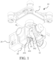
- an image photographing apparatus provided in an embodiment of the present application includes a gimbal 10 and a photographing device 20 disposed on the gimbal 10.
- the photographing device 20 may be a camera or a video camera, and may be configured to capture dynamic or static image information and to store the image information.
- the photographing device 20 includes a USB transmission interface 201.
- the photographing device 20 may be connected to an external storage device by using the USB transmission interface 201, for example, a computer and a removable hard disk, thereby transferring the image information in the photographing device 20 and satisfying other demands such as further processing.
- the gimbal 10 includes a main body 11 and a mounting shaft 12 disposed on the main body 11.
- the mounting shaft 12 is configured to be connected to a base 30 that may be mounted with the photographing device 20, thereby fastening the photographing device 20 to the gimbal 10.
- the main body 11 is a three-axis aerial photographing main body.
- the main body 11 may further include mechanisms such as a turnover support, a yaw support, a pitching motor, a turnover motor and a yaw motor.
- the mechanisms may control the photographing device 20 to implement moving and positioning on a three-dimensional space, thereby providing the photographing device 20 with various photographing angles and postures, to enrich image content and improve image quality.
- the mounting shaft 12 may be fixedly connected to the turnover support or the yaw support. By using a fixed connection between the main body 11 and the mounting shaft 12, switching of each action and fixing of each posture of the three-axis aerial photographing main body can be transmitted to the photographing device 20 disposed on the base 30.
- the gimbal 10 further includes a fixing plate 40 disposed on the base 30 and a circuit board 50 mounted between the fixing plate 40 and the base 30.
- the circuit board 50 is provided with a USB input interface 501 and a USB output interface 502.
- the USB input interface 501 is configured to form a data transmission connection to the photographing device 20.
- the USB output interface 502 is configured to be connected to an external storage device. Specifically, when the photographing device 20 is fixedly mounted on the base 30, the USB input interface 501 and the USB transmission interface 201 on the photographing device 20 form a data transmission connection.
- the photographing device 20 when data information in the photographing device 20 needs to be accessed, the photographing device 20 does not need to be dismounted from the gimbal 10.
- a further processing operation may be directly performed on the data information in the photographing device 20 by connecting the USB output interface 502 to the external storage device. Therefore, a trouble of repeatedly dismounting and mounting the photographing device 20 can be avoided. Friction losses of related structures of the photographing device 20 and the gimbal 10 are avoided, thereby prolonging service lives of the components.
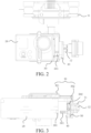
- the base 30 is approximately L-shaped and includes a first supporting plate 30 1 and a second supporting plate 302.
- the first supporting plate 301 is approximately perpendicular to the second supporting plate 302.
- the photographing device 20 is fastened to the first supporting plate 301.
- the fixing plate 40 is disposed on the second supporting plate 302.
- the circuit board 50 is sandwiched between the second supporting plate 302 and the fixing plate 40.
- the base 30 is provided with a mounting sleeve 31.
- the mounting sleeve 31 extends from a side of the second supporting plate 302.
- the mounting sleeve 31 and the circuit board 50 are respectively located on two opposite sides of the second supporting plate 302. That is, the mounting sleeve 31 is disposed on a side of the second supporting plate 302 opposite to the circuit board 50.
- the mounting sleeve 31 is sleeved on the mounting shaft 12, thereby fixedly mounting the mounting shaft 12 on the base 30.
- the mounting sleeve 31 is provided with a fastening screw. A fixed connection between the base 30 and the mounting shaft 12 may form by using the fastening screw.
- an insertion/removal direction of the USB output interface 502 is perpendicular to an axial direction of the mounting shaft 12. It can be understood that the insertion/removal direction of the USB output interface 502 and an insertion/removal direction of the USB input interface 501 refer to an insertion/removal direction of a USB device (for example, a USB data line or a USB storage) when the interfaces are connected to the USB device. It can be clearly seen from FIG. 1 , The USB output interface 502 is oriented downwards. The insertion/removal direction is a vertical direction and has a vertical relationship with the mounting shaft 12 that extends in a horizontal direction.
- the USB input interface 501 and the axial direction of the mounting shaft 12 are basically parallel, but are not coaxial, and have a stereoscopically staggered position relationship. Insertion/removal directions of the USB output interface 502 and the USB input interface 501 are different, so that the USB output interface 502 has larger connection space. It is avoided that the related structures of the photographing device 20 and the gimbal 10 block the USB output interface 502, thereby facilitating the connection between the USB output interface 502 and the external storage device.
- the circuit board 50 is sandwiched between the fixing plate 40 and the second supporting plate 302, so that the USB output interface 502 is also located between the fixing plate 40 and the second supporting plate 302.
- the USB input interface 501 is exposed from the fixing plate 40, to be connected to the photographing device 20 disposed on the base 30.
- the fixing plate 40 is provided with a through hole (not shown) to expose the USB input interface 501.
- One side of the fixing plate 40 is the circuit board 50, and the other side of the fixing plate 40 is connected to the photographing device 20 by using the USB input interface 501.
- a side of the circuit board 50 abutting against the second supporting plate further abuts against the mounting sleeve 31 and the mounting shaft 12.
- the fixing plate 40 covers on the second supporting plate 302 of the base 30, and fastens the circuit board 50. It can be understood that structures such as a slide rail and a mounting rib may further be disposed on the first supporting plate 301 of the base 30, to facilitate mounting and fastening of the photographing device 20.
- a circuit board 50 is connected to and disposed on the base 30 that fastens the photographing device 20, and a corresponding USB transferring interface is disposed on the circuit board 50, thereby simplifying a data transmission manner of the photographing device 20 on the gimbal 10, reducing risk of friction losses during dismounting of the gimbal 10 and the photographing device 20 and prolonging a service life of a related device.
- a USB transmission data line is needed so that real-time data or stored data in the photographing device 20 fastened to the gimbal 10 can be transmitted to a data storage device such as a mobile device of a user. This provides better user experience.
- the present application further provides an unmanned aerial vehicle that includes the foregoing image photographing apparatus.
- the unmanned aerial vehicle includes a main vehicle body.
- the image photographing apparatus is connected to the main vehicle body.
Landscapes
- Engineering & Computer Science (AREA)
- General Engineering & Computer Science (AREA)
- Mechanical Engineering (AREA)
- Aviation & Aerospace Engineering (AREA)
- Physics & Mathematics (AREA)
- General Physics & Mathematics (AREA)
- Microelectronics & Electronic Packaging (AREA)
- Remote Sensing (AREA)
- Studio Devices (AREA)
- Accessories Of Cameras (AREA)
- Control Of Position, Course, Altitude, Or Attitude Of Moving Bodies (AREA)
Claims (4)
- Bildfotografiervorrichtung, die eine kardanische Aufhängung (10) und eine Fotografiervorrichtung (20) aufweist, die im Gebrauch auf der kardanischen Aufhängung (10) angebracht ist, wobei die Fotografiervorrichtung (20) eine USB-Übertragungsschnittstelle (201) aufweist, wobei die kardanische Aufhängung (10) aufweist:einen Hauptkörper (11);eine Befestigungswelle (12), die mit dem Hauptkörper (11) verbunden ist, undeine Basis (30), die auf der Befestigungswelle (12) angeordnet ist, wobei die Basis (30) so konfiguriert ist, dass sie die Fotografiervorrichtung (20) befestigt;wobei die kardanische Aufhängung (10) außerdem umfasst:eine Befestigungsplatte (40), die auf der Basis (30) angeordnet ist, undeine Leiterplatte (50), die zwischen der Befestigungsplatte (40) und der Basis (30) angebracht ist, wobei die Leiterplatte (50) mit einer USB-Eingangsschnittstelle (501) und einer USB-Ausgangsschnittstelle (502) versehen ist, wobei die USB-Eingangsschnittstelle (501) so konfiguriert ist, dass sie eine Datenübertragungsverbindung mit der Fotografiervorrichtung (20) bildet, und die USB-Ausgangsschnittstelle (502) so konfiguriert ist, dass sie mit einer externen Speichervorrichtung verbunden wird;wobei die Basis (30) L-förmig ist und eine erste Trägerplatte (301) und eine zweite Trägerplatte (302) umfasst, wobei die Fotografiervorrichtung (20) im Gebrauch an der ersten Trägerplatte (30) befestigt ist, wobei die Befestigungsplatte (40) auf der zweiten Trägerplatte (302) angeordnet ist, und wobei die Leiterplatte (50) zwischen der zweiten Trägerplatte (302) und der Befestigungsplatte (40) angeordnet ist;wobei sich die USB-Eingangsschnittstelle (501) in Richtung der Fotografiervorrichtung (20) erstreckt, wobei die USB-Übertragungsschnittstelle (201) im Gebrauch eine Datenübertragung mit der USB-Eingangsschnittstelle (501) durchführt, wobei eine Einführungs-/Entfernungsrichtung der USB-Ausgangsschnittstelle (502) senkrecht zu der der USB-Eingangsschnittstelle (501) ist;wobei eine Montagehülse (31) auf einer der Leiterplatte (50) gegenüberliegenden Seite der zweiten Trägerplatte (302) angeordnet ist und die Montagehülse (31) auf die Montagewelle (12) gesteckt wird, um die Basis (30) und die Befestigungswelle (12) fest zu verbinden;wobei die USB-Ausgangsschnittstelle (502) zwischen der Befestigungsplatte (40) und der Montagehülse (31) angeordnet ist;wobei die Einführungs-/Entfernungsrichtung der USB-Ausgangsschnittstelle (502) senkrecht zu einer axialen Richtung der Befestigungswelle (12) ist.
- Bildfotografiervorrichtung nach Anspruch 1, wobei eine Seite der Leiterplatte (50), die an der zweiten Trägerplatte (302) anliegt, außerdem an der Montagehülse (31) und der Befestigungswelle (12) anliegt.
- Bildfotografiervorrichtung nach Anspruch 1, wobei die Befestigungsplatte (40) mit einem Durchgangsloch versehen ist, um die USB-Eingangsschnittstelle (501) freizulegen, wobei eine Seite der Befestigungsplatte (40) die Leiterplatte (50) ist, wobei die andere Seite der Befestigungsplatte (40) unter Verwendung der USB-Eingangsschnittstelle (501) mit der Fotografiervorrichtung (20) verbunden ist.
- Unbemanntes Luftfahrzeug, umfassend die Bildfotografiervorrichtung nach einem der Ansprüche 1 bis 3 und einen Hauptfahrzeugkörper, wobei die Bildfotografiervorrichtung mit dem Hauptfahrzeugkörper verbunden ist.
Applications Claiming Priority (2)
| Application Number | Priority Date | Filing Date | Title |
|---|---|---|---|
| CN201520881184.7U CN205101801U (zh) | 2015-11-06 | 2015-11-06 | 无人飞行器、影像拍摄装置及其云台 |
| PCT/CN2016/092765 WO2017076079A1 (zh) | 2015-11-06 | 2016-08-01 | 无人飞行器、影像拍摄装置及其云台 |
Publications (3)
| Publication Number | Publication Date |
|---|---|
| EP3372888A4 EP3372888A4 (de) | 2018-09-12 |
| EP3372888A1 EP3372888A1 (de) | 2018-09-12 |
| EP3372888B1 true EP3372888B1 (de) | 2023-05-24 |
Family
ID=55517582
Family Applications (1)
| Application Number | Title | Priority Date | Filing Date |
|---|---|---|---|
| EP16861349.5A Active EP3372888B1 (de) | 2015-11-06 | 2016-08-01 | Unbemanntes luftfahrzeug, bildfotografievorrichtung und wiegenkopf dafür |
Country Status (4)
| Country | Link |
|---|---|
| US (1) | US10287032B2 (de) |
| EP (1) | EP3372888B1 (de) |
| CN (1) | CN205101801U (de) |
| WO (1) | WO2017076079A1 (de) |
Families Citing this family (14)
| Publication number | Priority date | Publication date | Assignee | Title |
|---|---|---|---|---|
| US9454064B2 (en) | 2014-02-04 | 2016-09-27 | Disney Enterprises, Inc. | Motorized monopod jib for cameras |
| CN105518369B (zh) * | 2014-11-28 | 2018-02-02 | 深圳市大疆灵眸科技有限公司 | 平移轴组件及其使用的云台 |
| US9798221B2 (en) | 2015-02-20 | 2017-10-24 | Disney Enterprises, Inc. | Motorized monopod jib for cameras |
| CN205101801U (zh) * | 2015-11-06 | 2016-03-23 | 深圳市道通智能航空技术有限公司 | 无人飞行器、影像拍摄装置及其云台 |
| US10547773B2 (en) | 2016-10-28 | 2020-01-28 | Disney Enterprises, Inc. | User interface aspects for a motorized monopod jib for cameras |
| US10583556B2 (en) * | 2017-06-30 | 2020-03-10 | Disney Enterprises, Inc. | Motion stabilization on a motorized monopod jib |
| USD848383S1 (en) | 2017-07-13 | 2019-05-14 | Fat Shark Technology SEZC | Printed circuit board |
| USD825381S1 (en) | 2017-07-13 | 2018-08-14 | Fat Shark Technology SEZC | Unmanned aerial vehicle |
| US10179647B1 (en) | 2017-07-13 | 2019-01-15 | Fat Shark Technology SEZC | Unmanned aerial vehicle |
| CN207117778U (zh) * | 2017-07-21 | 2018-03-16 | 深圳市大疆创新科技有限公司 | 影像摄取装置、可移动平台和影像摄取设备 |
| CN107314215A (zh) * | 2017-08-16 | 2017-11-03 | 桂林智神信息技术有限公司 | 一种手持稳定器连接控制装置 |
| USD951333S1 (en) * | 2017-12-27 | 2022-05-10 | Autel Robotics Co., Ltd. | Gimbal camera |
| CN108413229B (zh) * | 2018-03-29 | 2025-02-11 | 北京小米移动软件有限公司 | 手持云台 |
| CN110908220B (zh) * | 2019-11-30 | 2025-01-14 | 陈鸿刚 | 一种便携式摄影棚 |
Family Cites Families (14)
| Publication number | Priority date | Publication date | Assignee | Title |
|---|---|---|---|---|
| US8087315B2 (en) * | 2006-10-10 | 2012-01-03 | Honeywell International Inc. | Methods and systems for attaching and detaching a payload device to and from, respectively, a gimbal system without requiring use of a mechanical tool |
| US9400555B2 (en) * | 2008-10-10 | 2016-07-26 | Internet Services, Llc | System and method for synchronization of haptic data and media data |
| US8325229B2 (en) * | 2008-11-26 | 2012-12-04 | Robert Bosch Gmbh | Camera having a slip ring and pan-tilt mechanism |
| US9154673B2 (en) * | 2013-02-04 | 2015-10-06 | Kenneth Stone | Cable camera systems and methods |
| CN203601575U (zh) * | 2013-10-22 | 2014-05-21 | 深圳一电科技有限公司 | 云台及飞行器 |
| CN112429255A (zh) * | 2014-04-28 | 2021-03-02 | 深圳市大疆创新科技有限公司 | 手持式平台 |
| CN104380725B (zh) * | 2014-05-25 | 2018-07-06 | 深圳市大疆灵眸科技有限公司 | 云台系统 |
| CN203859813U (zh) * | 2014-05-25 | 2014-10-01 | 深圳市大疆创新科技有限公司 | 云台系统 |
| CN204279973U (zh) * | 2014-11-07 | 2015-04-22 | 深圳一电科技有限公司 | 云台及具有其的无人机系统 |
| CN105518757B (zh) * | 2015-01-06 | 2018-06-12 | 深圳市大疆灵眸科技有限公司 | 云台遥控器及采用该云台遥控器的手持云台 |
| CN106662793B (zh) * | 2015-05-27 | 2019-06-11 | 高途乐公司 | 使用稳定用常平架的常平架系统 |
| CN205101801U (zh) * | 2015-11-06 | 2016-03-23 | 深圳市道通智能航空技术有限公司 | 无人飞行器、影像拍摄装置及其云台 |
| CN105539872A (zh) * | 2016-01-29 | 2016-05-04 | 北京小米移动软件有限公司 | 无人飞行器云台及其承载支架 |
| US20180244365A1 (en) * | 2017-02-24 | 2018-08-30 | Vantage Robotics, Llc | Modular uav with module identification |
-
2015
- 2015-11-06 CN CN201520881184.7U patent/CN205101801U/zh not_active Expired - Lifetime
-
2016
- 2016-08-01 WO PCT/CN2016/092765 patent/WO2017076079A1/zh not_active Ceased
- 2016-08-01 EP EP16861349.5A patent/EP3372888B1/de active Active
-
2018
- 2018-05-04 US US15/971,416 patent/US10287032B2/en active Active
Also Published As
| Publication number | Publication date |
|---|---|
| EP3372888A4 (de) | 2018-09-12 |
| CN205101801U (zh) | 2016-03-23 |
| US10287032B2 (en) | 2019-05-14 |
| WO2017076079A1 (zh) | 2017-05-11 |
| US20180273203A1 (en) | 2018-09-27 |
| EP3372888A1 (de) | 2018-09-12 |
Similar Documents
| Publication | Publication Date | Title |
|---|---|---|
| US10287032B2 (en) | Unmanned aerial vehicle, image photographing apparatus and gimbal thereof | |
| WO2020108273A1 (en) | Transmission module, transmission mechanism, and mobile terminal | |
| US9710024B2 (en) | Electronic device | |
| US20120309462A1 (en) | Screen Expansion Dock for Smart Phone | |
| US20180210322A1 (en) | Apparatus and Method for Stabilizing Virtual Reality Camera Configurations | |
| CN204350178U (zh) | 云台系统 | |
| CN204362205U (zh) | 飞行器系统 | |
| US20210324996A1 (en) | Photographing apparatus, photographing device, and electronic device | |
| WO2018214031A1 (zh) | 一种控制方法、装置、设备及飞行器 | |
| WO2018066817A1 (ko) | 플렉시블 커넥터를 포함하는 전자 장치 | |
| US20190052785A1 (en) | Deformable structure that compensates for displacement of a camera module of a camera accessory | |
| US10205325B2 (en) | Providing power to integrated electronics within a cable | |
| CN205450783U (zh) | 一种无人机飞行控制及拍摄装置 | |
| CN205545612U (zh) | 相机模组及摄像装置 | |
| KR20180078008A (ko) | 마이크로 짐벌 카메라 | |
| CN215258753U (zh) | 桌面视觉跟踪云台 | |
| US10156317B2 (en) | Fixing structure | |
| CN207442989U (zh) | 应用于视频设备的图像稳定系统 | |
| CN111977007A (zh) | 云台、拍摄设备和无人飞行器 | |
| CN104935700A (zh) | 移动终端 | |
| CN105898989A (zh) | 一种可进行功能扩展的pcb装置,模块板及方法 | |
| KR101817715B1 (ko) | 멀티 비전 장치 | |
| CN205453884U (zh) | 一种车载摄像装置 | |
| CN205560154U (zh) | 一种夹持装置及无人机云台 | |
| US20180210569A1 (en) | Storage and control external to a computer system |
Legal Events
| Date | Code | Title | Description |
|---|---|---|---|
| STAA | Information on the status of an ep patent application or granted ep patent |
Free format text: STATUS: THE INTERNATIONAL PUBLICATION HAS BEEN MADE |
|
| PUAI | Public reference made under article 153(3) epc to a published international application that has entered the european phase |
Free format text: ORIGINAL CODE: 0009012 |
|
| STAA | Information on the status of an ep patent application or granted ep patent |
Free format text: STATUS: REQUEST FOR EXAMINATION WAS MADE |
|
| 17P | Request for examination filed |
Effective date: 20180503 |
|
| A4 | Supplementary search report drawn up and despatched |
Effective date: 20180716 |
|
| AK | Designated contracting states |
Kind code of ref document: A1 Designated state(s): AL AT BE BG CH CY CZ DE DK EE ES FI FR GB GR HR HU IE IS IT LI LT LU LV MC MK MT NL NO PL PT RO RS SE SI SK SM TR |
|
| AX | Request for extension of the european patent |
Extension state: BA ME |
|
| DAV | Request for validation of the european patent (deleted) | ||
| DAX | Request for extension of the european patent (deleted) | ||
| STAA | Information on the status of an ep patent application or granted ep patent |
Free format text: STATUS: EXAMINATION IS IN PROGRESS |
|
| 17Q | First examination report despatched |
Effective date: 20190619 |
|
| REG | Reference to a national code |
Ref country code: DE Ref legal event code: R079 Ref document number: 602016079634 Country of ref document: DE Free format text: PREVIOUS MAIN CLASS: F16M0011180000 Ipc: F16M0011100000 |
|
| RIC1 | Information provided on ipc code assigned before grant |
Ipc: B64D 47/08 20060101ALI20221018BHEP Ipc: F16M 13/02 20060101ALI20221018BHEP Ipc: F16M 11/18 20060101ALI20221018BHEP Ipc: F16M 11/20 20060101ALI20221018BHEP Ipc: F16M 11/12 20060101ALI20221018BHEP Ipc: F16M 11/10 20060101AFI20221018BHEP |
|
| GRAP | Despatch of communication of intention to grant a patent |
Free format text: ORIGINAL CODE: EPIDOSNIGR1 |
|
| STAA | Information on the status of an ep patent application or granted ep patent |
Free format text: STATUS: GRANT OF PATENT IS INTENDED |
|
| INTG | Intention to grant announced |
Effective date: 20221216 |
|
| GRAS | Grant fee paid |
Free format text: ORIGINAL CODE: EPIDOSNIGR3 |
|
| GRAA | (expected) grant |
Free format text: ORIGINAL CODE: 0009210 |
|
| STAA | Information on the status of an ep patent application or granted ep patent |
Free format text: STATUS: THE PATENT HAS BEEN GRANTED |
|
| AK | Designated contracting states |
Kind code of ref document: B1 Designated state(s): AL AT BE BG CH CY CZ DE DK EE ES FI FR GB GR HR HU IE IS IT LI LT LU LV MC MK MT NL NO PL PT RO RS SE SI SK SM TR |
|
| REG | Reference to a national code |
Ref country code: GB Ref legal event code: FG4D |
|
| REG | Reference to a national code |
Ref country code: CH Ref legal event code: EP |
|
| REG | Reference to a national code |
Ref country code: DE Ref legal event code: R096 Ref document number: 602016079634 Country of ref document: DE |
|
| REG | Reference to a national code |
Ref country code: AT Ref legal event code: REF Ref document number: 1569682 Country of ref document: AT Kind code of ref document: T Effective date: 20230615 |
|
| REG | Reference to a national code |
Ref country code: IE Ref legal event code: FG4D |
|
| REG | Reference to a national code |
Ref country code: LT Ref legal event code: MG9D |
|
| REG | Reference to a national code |
Ref country code: NL Ref legal event code: MP Effective date: 20230524 |
|
| REG | Reference to a national code |
Ref country code: AT Ref legal event code: MK05 Ref document number: 1569682 Country of ref document: AT Kind code of ref document: T Effective date: 20230524 |
|
| PG25 | Lapsed in a contracting state [announced via postgrant information from national office to epo] |
Ref country code: SE Free format text: LAPSE BECAUSE OF FAILURE TO SUBMIT A TRANSLATION OF THE DESCRIPTION OR TO PAY THE FEE WITHIN THE PRESCRIBED TIME-LIMIT Effective date: 20230524 Ref country code: PT Free format text: LAPSE BECAUSE OF FAILURE TO SUBMIT A TRANSLATION OF THE DESCRIPTION OR TO PAY THE FEE WITHIN THE PRESCRIBED TIME-LIMIT Effective date: 20230925 Ref country code: NO Free format text: LAPSE BECAUSE OF FAILURE TO SUBMIT A TRANSLATION OF THE DESCRIPTION OR TO PAY THE FEE WITHIN THE PRESCRIBED TIME-LIMIT Effective date: 20230824 Ref country code: NL Free format text: LAPSE BECAUSE OF FAILURE TO SUBMIT A TRANSLATION OF THE DESCRIPTION OR TO PAY THE FEE WITHIN THE PRESCRIBED TIME-LIMIT Effective date: 20230524 Ref country code: ES Free format text: LAPSE BECAUSE OF FAILURE TO SUBMIT A TRANSLATION OF THE DESCRIPTION OR TO PAY THE FEE WITHIN THE PRESCRIBED TIME-LIMIT Effective date: 20230524 Ref country code: AT Free format text: LAPSE BECAUSE OF FAILURE TO SUBMIT A TRANSLATION OF THE DESCRIPTION OR TO PAY THE FEE WITHIN THE PRESCRIBED TIME-LIMIT Effective date: 20230524 |
|
| PG25 | Lapsed in a contracting state [announced via postgrant information from national office to epo] |
Ref country code: RS Free format text: LAPSE BECAUSE OF FAILURE TO SUBMIT A TRANSLATION OF THE DESCRIPTION OR TO PAY THE FEE WITHIN THE PRESCRIBED TIME-LIMIT Effective date: 20230524 Ref country code: PL Free format text: LAPSE BECAUSE OF FAILURE TO SUBMIT A TRANSLATION OF THE DESCRIPTION OR TO PAY THE FEE WITHIN THE PRESCRIBED TIME-LIMIT Effective date: 20230524 Ref country code: LV Free format text: LAPSE BECAUSE OF FAILURE TO SUBMIT A TRANSLATION OF THE DESCRIPTION OR TO PAY THE FEE WITHIN THE PRESCRIBED TIME-LIMIT Effective date: 20230524 Ref country code: LT Free format text: LAPSE BECAUSE OF FAILURE TO SUBMIT A TRANSLATION OF THE DESCRIPTION OR TO PAY THE FEE WITHIN THE PRESCRIBED TIME-LIMIT Effective date: 20230524 Ref country code: IS Free format text: LAPSE BECAUSE OF FAILURE TO SUBMIT A TRANSLATION OF THE DESCRIPTION OR TO PAY THE FEE WITHIN THE PRESCRIBED TIME-LIMIT Effective date: 20230924 Ref country code: HR Free format text: LAPSE BECAUSE OF FAILURE TO SUBMIT A TRANSLATION OF THE DESCRIPTION OR TO PAY THE FEE WITHIN THE PRESCRIBED TIME-LIMIT Effective date: 20230524 Ref country code: GR Free format text: LAPSE BECAUSE OF FAILURE TO SUBMIT A TRANSLATION OF THE DESCRIPTION OR TO PAY THE FEE WITHIN THE PRESCRIBED TIME-LIMIT Effective date: 20230825 |
|
| PG25 | Lapsed in a contracting state [announced via postgrant information from national office to epo] |
Ref country code: FI Free format text: LAPSE BECAUSE OF FAILURE TO SUBMIT A TRANSLATION OF THE DESCRIPTION OR TO PAY THE FEE WITHIN THE PRESCRIBED TIME-LIMIT Effective date: 20230524 |
|
| PG25 | Lapsed in a contracting state [announced via postgrant information from national office to epo] |
Ref country code: SK Free format text: LAPSE BECAUSE OF FAILURE TO SUBMIT A TRANSLATION OF THE DESCRIPTION OR TO PAY THE FEE WITHIN THE PRESCRIBED TIME-LIMIT Effective date: 20230524 |
|
| PG25 | Lapsed in a contracting state [announced via postgrant information from national office to epo] |
Ref country code: SM Free format text: LAPSE BECAUSE OF FAILURE TO SUBMIT A TRANSLATION OF THE DESCRIPTION OR TO PAY THE FEE WITHIN THE PRESCRIBED TIME-LIMIT Effective date: 20230524 Ref country code: SK Free format text: LAPSE BECAUSE OF FAILURE TO SUBMIT A TRANSLATION OF THE DESCRIPTION OR TO PAY THE FEE WITHIN THE PRESCRIBED TIME-LIMIT Effective date: 20230524 Ref country code: RO Free format text: LAPSE BECAUSE OF FAILURE TO SUBMIT A TRANSLATION OF THE DESCRIPTION OR TO PAY THE FEE WITHIN THE PRESCRIBED TIME-LIMIT Effective date: 20230524 Ref country code: EE Free format text: LAPSE BECAUSE OF FAILURE TO SUBMIT A TRANSLATION OF THE DESCRIPTION OR TO PAY THE FEE WITHIN THE PRESCRIBED TIME-LIMIT Effective date: 20230524 Ref country code: DK Free format text: LAPSE BECAUSE OF FAILURE TO SUBMIT A TRANSLATION OF THE DESCRIPTION OR TO PAY THE FEE WITHIN THE PRESCRIBED TIME-LIMIT Effective date: 20230524 Ref country code: CZ Free format text: LAPSE BECAUSE OF FAILURE TO SUBMIT A TRANSLATION OF THE DESCRIPTION OR TO PAY THE FEE WITHIN THE PRESCRIBED TIME-LIMIT Effective date: 20230524 |
|
| REG | Reference to a national code |
Ref country code: DE Ref legal event code: R097 Ref document number: 602016079634 Country of ref document: DE |
|
| PG25 | Lapsed in a contracting state [announced via postgrant information from national office to epo] |
Ref country code: MC Free format text: LAPSE BECAUSE OF FAILURE TO SUBMIT A TRANSLATION OF THE DESCRIPTION OR TO PAY THE FEE WITHIN THE PRESCRIBED TIME-LIMIT Effective date: 20230524 |
|
| REG | Reference to a national code |
Ref country code: CH Ref legal event code: PL |
|
| PG25 | Lapsed in a contracting state [announced via postgrant information from national office to epo] |
Ref country code: MC Free format text: LAPSE BECAUSE OF FAILURE TO SUBMIT A TRANSLATION OF THE DESCRIPTION OR TO PAY THE FEE WITHIN THE PRESCRIBED TIME-LIMIT Effective date: 20230524 |
|
| PLBE | No opposition filed within time limit |
Free format text: ORIGINAL CODE: 0009261 |
|
| STAA | Information on the status of an ep patent application or granted ep patent |
Free format text: STATUS: NO OPPOSITION FILED WITHIN TIME LIMIT |
|
| PG25 | Lapsed in a contracting state [announced via postgrant information from national office to epo] |
Ref country code: LU Free format text: LAPSE BECAUSE OF NON-PAYMENT OF DUE FEES Effective date: 20230801 |
|
| PG25 | Lapsed in a contracting state [announced via postgrant information from national office to epo] |
Ref country code: LU Free format text: LAPSE BECAUSE OF NON-PAYMENT OF DUE FEES Effective date: 20230801 Ref country code: CH Free format text: LAPSE BECAUSE OF NON-PAYMENT OF DUE FEES Effective date: 20230831 |
|
| 26N | No opposition filed |
Effective date: 20240227 |
|
| PG25 | Lapsed in a contracting state [announced via postgrant information from national office to epo] |
Ref country code: SI Free format text: LAPSE BECAUSE OF FAILURE TO SUBMIT A TRANSLATION OF THE DESCRIPTION OR TO PAY THE FEE WITHIN THE PRESCRIBED TIME-LIMIT Effective date: 20230524 |
|
| REG | Reference to a national code |
Ref country code: BE Ref legal event code: MM Effective date: 20230831 |
|
| REG | Reference to a national code |
Ref country code: IE Ref legal event code: MM4A |
|
| PG25 | Lapsed in a contracting state [announced via postgrant information from national office to epo] |
Ref country code: SI Free format text: LAPSE BECAUSE OF FAILURE TO SUBMIT A TRANSLATION OF THE DESCRIPTION OR TO PAY THE FEE WITHIN THE PRESCRIBED TIME-LIMIT Effective date: 20230524 Ref country code: IT Free format text: LAPSE BECAUSE OF FAILURE TO SUBMIT A TRANSLATION OF THE DESCRIPTION OR TO PAY THE FEE WITHIN THE PRESCRIBED TIME-LIMIT Effective date: 20230524 |
|
| PG25 | Lapsed in a contracting state [announced via postgrant information from national office to epo] |
Ref country code: IE Free format text: LAPSE BECAUSE OF NON-PAYMENT OF DUE FEES Effective date: 20230801 |
|
| PG25 | Lapsed in a contracting state [announced via postgrant information from national office to epo] |
Ref country code: IE Free format text: LAPSE BECAUSE OF NON-PAYMENT OF DUE FEES Effective date: 20230801 |
|
| PG25 | Lapsed in a contracting state [announced via postgrant information from national office to epo] |
Ref country code: BE Free format text: LAPSE BECAUSE OF NON-PAYMENT OF DUE FEES Effective date: 20230831 |
|
| PGFP | Annual fee paid to national office [announced via postgrant information from national office to epo] |
Ref country code: GB Payment date: 20240826 Year of fee payment: 9 |
|
| PG25 | Lapsed in a contracting state [announced via postgrant information from national office to epo] |
Ref country code: BG Free format text: LAPSE BECAUSE OF FAILURE TO SUBMIT A TRANSLATION OF THE DESCRIPTION OR TO PAY THE FEE WITHIN THE PRESCRIBED TIME-LIMIT Effective date: 20230524 |
|
| PG25 | Lapsed in a contracting state [announced via postgrant information from national office to epo] |
Ref country code: BG Free format text: LAPSE BECAUSE OF FAILURE TO SUBMIT A TRANSLATION OF THE DESCRIPTION OR TO PAY THE FEE WITHIN THE PRESCRIBED TIME-LIMIT Effective date: 20230524 |
|
| PG25 | Lapsed in a contracting state [announced via postgrant information from national office to epo] |
Ref country code: CY Free format text: LAPSE BECAUSE OF FAILURE TO SUBMIT A TRANSLATION OF THE DESCRIPTION OR TO PAY THE FEE WITHIN THE PRESCRIBED TIME-LIMIT; INVALID AB INITIO Effective date: 20160801 |
|
| PG25 | Lapsed in a contracting state [announced via postgrant information from national office to epo] |
Ref country code: HU Free format text: LAPSE BECAUSE OF FAILURE TO SUBMIT A TRANSLATION OF THE DESCRIPTION OR TO PAY THE FEE WITHIN THE PRESCRIBED TIME-LIMIT; INVALID AB INITIO Effective date: 20160801 |
|
| PGFP | Annual fee paid to national office [announced via postgrant information from national office to epo] |
Ref country code: DE Payment date: 20250820 Year of fee payment: 10 |
|
| PGFP | Annual fee paid to national office [announced via postgrant information from national office to epo] |
Ref country code: FR Payment date: 20250828 Year of fee payment: 10 |
|
| PG25 | Lapsed in a contracting state [announced via postgrant information from national office to epo] |
Ref country code: TR Free format text: LAPSE BECAUSE OF FAILURE TO SUBMIT A TRANSLATION OF THE DESCRIPTION OR TO PAY THE FEE WITHIN THE PRESCRIBED TIME-LIMIT Effective date: 20230524 |
|
| GBPC | Gb: european patent ceased through non-payment of renewal fee |
Effective date: 20250801 |