EP3372504B1 - Beleuchtete staufächer in fahrzeugen - Google Patents
Beleuchtete staufächer in fahrzeugen Download PDFInfo
- Publication number
- EP3372504B1 EP3372504B1 EP18160758.1A EP18160758A EP3372504B1 EP 3372504 B1 EP3372504 B1 EP 3372504B1 EP 18160758 A EP18160758 A EP 18160758A EP 3372504 B1 EP3372504 B1 EP 3372504B1
- Authority
- EP
- European Patent Office
- Prior art keywords
- stowage bin
- bin assembly
- emitting elements
- stowage
- baggage
- Prior art date
- Legal status (The legal status is an assumption and is not a legal conclusion. Google has not performed a legal analysis and makes no representation as to the accuracy of the status listed.)
- Active
Links
Images


Classifications
-
- B—PERFORMING OPERATIONS; TRANSPORTING
- B60—VEHICLES IN GENERAL
- B60Q—ARRANGEMENT OF SIGNALLING OR LIGHTING DEVICES, THE MOUNTING OR SUPPORTING THEREOF OR CIRCUITS THEREFOR, FOR VEHICLES IN GENERAL
- B60Q3/00—Arrangement of lighting devices for vehicle interiors; Lighting devices specially adapted for vehicle interiors
- B60Q3/30—Arrangement of lighting devices for vehicle interiors; Lighting devices specially adapted for vehicle interiors for compartments other than passenger or driving compartments, e.g. luggage or engine compartments
-
- B—PERFORMING OPERATIONS; TRANSPORTING
- B61—RAILWAYS
- B61D—BODY DETAILS OR KINDS OF RAILWAY VEHICLES
- B61D29/00—Lighting
-
- B—PERFORMING OPERATIONS; TRANSPORTING
- B64—AIRCRAFT; AVIATION; COSMONAUTICS
- B64D—EQUIPMENT FOR FITTING IN OR TO AIRCRAFT; FLIGHT SUITS; PARACHUTES; ARRANGEMENT OR MOUNTING OF POWER PLANTS OR PROPULSION TRANSMISSIONS IN AIRCRAFT
- B64D11/00—Passenger or crew accommodation; Flight-deck installations not otherwise provided for
- B64D11/003—Stowage devices for passengers' personal luggage
-
- B—PERFORMING OPERATIONS; TRANSPORTING
- B60—VEHICLES IN GENERAL
- B60Q—ARRANGEMENT OF SIGNALLING OR LIGHTING DEVICES, THE MOUNTING OR SUPPORTING THEREOF OR CIRCUITS THEREFOR, FOR VEHICLES IN GENERAL
- B60Q3/00—Arrangement of lighting devices for vehicle interiors; Lighting devices specially adapted for vehicle interiors
- B60Q3/40—Arrangement of lighting devices for vehicle interiors; Lighting devices specially adapted for vehicle interiors specially adapted for specific vehicle types
- B60Q3/41—Arrangement of lighting devices for vehicle interiors; Lighting devices specially adapted for vehicle interiors specially adapted for specific vehicle types for mass transit vehicles, e.g. buses
-
- B—PERFORMING OPERATIONS; TRANSPORTING
- B64—AIRCRAFT; AVIATION; COSMONAUTICS
- B64D—EQUIPMENT FOR FITTING IN OR TO AIRCRAFT; FLIGHT SUITS; PARACHUTES; ARRANGEMENT OR MOUNTING OF POWER PLANTS OR PROPULSION TRANSMISSIONS IN AIRCRAFT
- B64D11/00—Passenger or crew accommodation; Flight-deck installations not otherwise provided for
- B64D2011/0038—Illumination systems for cabins as a whole
-
- Y—GENERAL TAGGING OF NEW TECHNOLOGICAL DEVELOPMENTS; GENERAL TAGGING OF CROSS-SECTIONAL TECHNOLOGIES SPANNING OVER SEVERAL SECTIONS OF THE IPC; TECHNICAL SUBJECTS COVERED BY FORMER USPC CROSS-REFERENCE ART COLLECTIONS [XRACs] AND DIGESTS
- Y02—TECHNOLOGIES OR APPLICATIONS FOR MITIGATION OR ADAPTATION AGAINST CLIMATE CHANGE
- Y02T—CLIMATE CHANGE MITIGATION TECHNOLOGIES RELATED TO TRANSPORTATION
- Y02T30/00—Transportation of goods or passengers via railways, e.g. energy recovery or reducing air resistance
Definitions
- Embodiments of the present disclosure generally relate to interior cabins within vehicles, such as commercial aircraft, and, more particularly, to electronic stowage bin control systems and methods within interior cabins of vehicles.
- a cockpit is generally separated from a passenger cabin, which may include a first class section, a business class section, and a coach section.
- the passenger cabin may also include one or more work areas for flight personnel, such as galleys, which may include food and beverage storage structures.
- One or more aisles pass through the passenger cabin and connect each of the passenger sections to one or more paths to one or more doors of the aircraft.
- Overhead stowage bins are typically positioned above rows of seats within a commercial aircraft. Each overhead stowage bin is configured to be moved between an open position and a closed position. In the open position, passengers may place carry-on luggage within a moveable bin or bucket. Before the aircraft leaves a terminal, flight attendants ensure that each stowage bin is securely closed.
- an individual In order to open a stowage bin, an individual (such as a passenger or flight attendant) physically touches a latch of the stowage bin. For example, the individual first grasps and pulls the latch in order to manipulate the stowage bin into an open position.
- the latch of the stowage bin is touched by numerous individuals many times. Consequently, various germs and bacteria may be present on the latch if the latch is not regularly cleaned. Moreover, certain individuals may find grasping and manipulating the latch difficult.
- WO 2007/118981 discloses a luggage compartment comprising a sealed compartment located in a space designed to accommodate travelers in a vehicle. It has at least one wall defining it and visible from the traveler space in which it is located. The wall contains at least one opening closed by a transparent material.
- DE 3630408 discloses a rack for accommodating or storing objects such as covers, handluggage or the like in land, air or waterborne vehicles.
- the lateral insertion aperture of the rack has a flap which is articulated to the top of the vehicle, can be pivoted upwards to permit opening of the rack and in the essentially vertical closed position extends flush with the lower edge of the insertion aperture, which edge takes the form of a hand rail which is integrated with the rack.
- the flap itself has, on its lower, non-articulated end, at least one gripping recess, it being possible, when the flap is closed, for a person to take hold of the hand rail to support himself/herself.
- the recess can also be used to take hold of the closed flap itself, so that the latter can be opened upwards.
- EP 2,868,963 discloses an illumination device including an organic electroluminescence (EL) illumination panel installed in a baggage rack or the like in a fuselage of an aircraft, and a panel driving circuit that drives the organic EL illumination panel and is installed in a different place apart from the organic EL illumination panel in the fuselage to drive the organic EL illumination panel.
- the organic EL illumination panel includes a plurality of light emitting units including at least a light emitting layer, and a charge generation layer arranged between the plurality of light emitting units to thereby form a multi-photoemission structure, and has a thickness of 5 mm or less in a stacking direction.
- EP 2,865,597 discloses an overhead bin assembly for transport vehicles (e.g., transport category aircraft) that is provided with a generally U-shaped bin shell having a bottom wall, an outboard end wall and an upper wall defining an interior stowage space having an inboard opening opposite the end wall.
- a pair of separated transverse bin supports defining a bin space therebetween may be provided along with a bin door for closing the inboard opening.
- a cantilever hinge may be provided so as to connect the bin door to the transverse bin support in a cantilever manner to allow for pivotal movement of the bin door between closed and open positions relative to the inboard opening.
- An arcuate recessed wall may be positioned inboard relative to the upper wall of the bin shell (e.g., as a unitary (one-piece) extension thereof) such that the bin door is received within the recessed wall when in the open position thereof.
- DE 20016406 U1 discloses a handle for land, air and water vehicles for passenger transport, characterized in that the running in the longitudinal direction of the vehicle, formed from an extruded profile longitudinal profiles are designed as a light rail.
- EP 3 173 329 Al discloses a system for monitoring an overhead storage bin that includes a proximity sensor, a load sensor, a latch mechanism sensor, and a controller operatively connected to the proximity sensor, the load sensor and the latch mechanism sensor.
- the controller is configured to retrieve proximity data from the proximity sensor indicative of a space status of an overhead storage bin, retrieve load data from the load sensor indicative of a stowage weight status of the bin, and retrieve a latch status from the latch mechanism sensor indicative of a latch status of an access door of the bin.
- the controller is further configured to determine, based on the space status, the weight data, and the latch status, a probability indicative of whether an item stowed in the bin may fall from the bin, and output, based on the probability, an indication on an output device on an exterior surface of the bin.
- a vehicle comprising: an interior cabin; and a stowage bin assembly within the interior cabin, the stowage bin assembly comprising a stowage bin control unit and one or more interior light-emitting elements configured to illuminate a baggage retaining chamber of the stowage bin assembly.
- the stowage bin control unit is in communication with the one or more interior light-emitting elements and the stowage bin control unit is configured to operate the one or more interior light-emitting elements.
- the stowage bin assembly further comprises a weight sensor configured to detect the weight of the stowage bin assembly and/or any baggage placed within the stowage bin assembly.
- the stowage bin assembly is configured to determine whether there is space in the stowage bin assembly for further baggage based on the detected weight or whether the stowage bin assembly is overloaded based on the detected weight.
- the interior light emitting elements are configured to operate in conjunction with the stowage bin control unit and in conjunction with the weight sensor to indicate whether there is space in the stowage bin assembly for further baggage, whether the stowage bin assembly (502) is full, or whether the stowage bin assembly (502) is overloaded .
- the method comprises using a weight sensor to detect the weight of the stowage bin assembly and/or any baggage placed within the stowage bin assembly.
- the method also comprises determining whether there is space in the stowage bin assembly for further baggage based on the detected weight or whether the stowage bin assembly is full or overloaded based on the weight detected by the weight sensor.
- the method also comprises using a stowage bin control unit to illuminate a baggage retaining chamber of the stowage bin assembly with one or more interior light-emitting elements.
- the illuminating comprises emitting light such that the interior light emitting elements indicate a status of the stowage bin assembly by emitting light such that the interior light emitting elements indicate whether there is space in the stowage bin assembly for further baggage or whether the stowage bin assembly is full, or whether the stowage bin assembly is overloaded, based on the weight detected by the weight sensor.
- the present disclosure further describes an unclaimed stowage bin control system for a vehicle.
- the stowage bin control system includes at least one stowage bin assembly that is configured to be selectively moved between an open position and a closed position.
- a master control device is separate and distinct from the stowage bin assemblies.
- the master control device is communicatively coupled through a wireless connection to the stowage bin assemblies and is configured to operate the stowage bin assemblies.
- the master control device is configured to automatically move the stowage bin assemblies between the open position and the closed position.
- Each stowage bin assembly includes a latch that is configured to selectively lock and unlock the stowage bin assembly.
- the master control device is configured to automatically lock and unlock the latch.
- the latch is operatively coupled to one or more latching mechanisms.
- the master control device includes a master stowage bin control unit that is in communication with stowage bin assemblies.
- One or more of the stowage bin assemblies may include a stowage bin control unit in communication with the master stowage bin control unit.
- the master control device may include a user interface that is configured to allow an individual to input commands.
- a plurality of stowage bin assemblies may be communicatively coupled to the master control device.
- the master control device may simultaneously open or close the plurality of stowage bin assemblies.
- the master control device may open or close the plurality of stowage bin assemblies in a staggered fashion.
- the master control device may synchronize opening or closing of the stowage bin assemblies with lighting effects, sounds, graphics, and/or video.
- the master control device is configured to transition the stowage bin assemblies into a manual override mode in which a user is able to manually open and close the stowage bin assemblies in response to reception of one or more error signals from the stowage bin assemblies.
- the stowage bin assemblies may be configured to output report signals to the master control device.
- the report signals includes data regarding operational health or status.
- the stowage bin assembly may include a proximity sensor that is configured to detect presence of an object within a detection range.
- the proximity sensor may be mounted to an outer surface of the stowage bin assembly.
- the proximity sensor may be configured to selectively switch the stowage bin assembly between a locked and unlocked state.
- the stowage bin assembly may include one or more exterior light-emitting elements.
- the exterior light-emitting elements are configured to emit light to indicate a current status of the stowage bin assembly.
- the exterior light-emitting element(s) may be proximate to a latch of the stowage bin assembly.
- the stowage bin assembly may include a motion sensor that is configured to detect motion within a detection range.
- the motion sensor may be proximate to a latch of the stowage bin assembly.
- the motion sensor may be configured to be engaged to automatically open or close the stowage bin assembly without an individual touching the stowage bin assembly.
- the stowage bin assembly includes one or more interior light-emitting elements.
- the light-emitting element(s) may be disposed within a baggage retaining chamber of the stowage bin assembly.
- the interior light-emitting element(s) is(are) configured to illuminate a baggage retaining chamber of the stowage bin assembly.
- the interior light-emitting element(s) may be configured to illuminate the baggage retaining chamber when the stowage bin assembly is in the open position, and may be deactivated when the stowage bin assembly is in the closed position.
- the interior light-emitting element(s) emit light that gradually intensifies as the stowage bin assembly is opened, and emit light that gradually fades as the stowage bin assembly is closed.
- the stowage bin assembly may include a bin position sensor that is configured to detect a position of the stowage bin assembly.
- the stowage bin assembly may include at least one touch sensor that is configured to be touched in order to lock, unlock, close, and/or open the stowage bin assembly.
- the stowage bin assembly includes a bucket having a front panel connected to a forward end panel and an aft end panel.
- a baggage retaining chamber is defined, at least in part, between the front panel, the forward end panel, and the aft panel.
- the front panel may include an arcuate panel having a curved outer surface.
- the stowage bin control method includes wirelessly communicatively coupling a master control device to at least one stowage bin assembly within the vehicle, and using the master control device to operate the stowage bin assembly.
- the present disclosure further describes an unclaimed latch of the stowage bin assembly that is configured to selectively lock and unlock the stowage bin assembly.
- the stowage bin assembly may also include one or more of a proximity sensor that is configured to detect presence of an object, a motion sensor that is configured to detect motion within a detection range, or at least one touch sensor that is configured to be touched in order to lock, unlock, close, and/or open the stowage bin assembly.
- the stowage bin assembly may also include one or more exterior light-emitting elements.
- the exterior light-emitting elements are configured to emit light to indicate a current status of the stowage bin assembly.
- the stowage bin assembly also includes one more interior light-emitting elements configured to illuminate a baggage retaining chamber of the stowage bin assembly, and a weight sensor that is configured to detect the weight of the stowage bin assembly.
- the stowage bin assembly may further include a bin position sensor that is configured to detect a position of the stowage bin assembly.
- Certain unclaimed configurations of the present disclosure provide a latch of the stowage bin assembly that is configured to selectively lock and unlock the stowage bin assembly, and a sensor in communication with the latch.
- the sensor is configured to be engaged to lock, unlock, open, and/or close the stowage bin assembly without the latch or the sensor being touched.
- the senor includes a proximity sensor that is configured to detect presence of an object within a detection range. In at least one unclaimed example, the sensor includes a motion sensor that is configured to detect motion within a detection range.
- Certain unclaimed examples of the present disclosure further provide a method of operating a stowage bin assembly.
- the method includes communicatively coupling a latch that is configured to selectively lock and unlock the stowage bin assembly to a sensor, and engaging the sensor to one or more of lock, unlock, open, or close the stowage bin assembly without the latch or the sensor being touched.
- the present disclosure provides a stowage bin assembly that includes one or more interior light-emitting elements configured to illuminate a baggage retaining chamber of the stowage bin assembly.
- the interior light-emitting elements may be disposed within the baggage retaining chamber of the stowage bin assembly.
- the interior light-emitting elements are configured to illuminate the baggage retaining chamber when the stowage bin assembly is in an open position, and wherein the one or more interior light-emitting elements are deactivated when the stowage bin assembly is in a closed position.
- the interior light-emitting elements may emit light that gradually intensifies as the stowage bin assembly is opened, and gradually fades as the stowage bin assembly is closed.
- the present disclosure provides a method that includes illuminating a baggage retaining chamber of the stowage bin assembly with one or more interior light-emitting elements.
- the stowage bin assembly further includes a weight sensor that is configured to detect the weight of the stowage bin assembly.
- Embodiments of the present disclosure further provide a method of operating a stowage bin assembly that includes detecting a weight of the stowage bin assembly using a weight sensor of the stowage bin assembly.
- Certain unclaimed examples of the present disclosure may be used with touch-free activated stowage bin assemblies.
- the stowage bin assemblies may be selectively moved between open and closed positions without an individual physically touching them. Further, the stowage bin assemblies may be controlled by one or more stowage bin control units.
- the stowage bin control units may be operated by aircraft personnel (such as a pilot or flight attendant) to prevent passengers from opening the stowage bin assemblies during restricted periods (such as takeoff, landing, periods of turbulence, and the like).
- stowage bin assemblies include an electronic latch that is configured to be automatically locked and opened.
- the latch may include a sensor (such as proximity or motion sensor) that is configured to detect hand motion within a predefined detection range (such as within 3 or 4 inches (8 or 10 centimetres) from the sensor). In this manner, an individual may move a hand within close proximity of the latch (such as within six inches (15 centimetres) or less) to operatively engage the latch without physically touching the latch. Individuals may simply wave their hands in front of the latch to automatically open the stowage bin assembly.
- a sensor such as proximity or motion sensor
- a stowage bin control unit in communication with the latches of the stowage bin assemblies may be used to lock the latches, and prevent the latches from switching to open states. In this manner, aircraft personnel may lock the latches to prevent passengers from opening the stowage bin assemblies.
- the stowage bin control unit may be within a computer onboard the aircraft, such as within a work station or control panel in a galley or cockpit.
- the stowage bin control unit may be within a handheld device, such as a handheld smart device or cellular phone.
- Flight personnel may swipe a badge in front of the latch to set the latch in a locked state.
- the latch may include one or more light-emitting elements (such as light emitting diodes - LEDs) that indicate whether or not the latch is locked. For example, in the locked state, a light-emitting element may emit red light. In an unlocked state, the light-emitting element may emit green light.
- the stowage bin system may include a stowage bin assembly having a latching mechanism coupled to a door, an electrical button on or proximal to the stowage bin assembly to control the electric latch, and an electric drive system to at least assist with forces required to manipulate the bin through at least a portion of its range of motion.
- Aircraft personnel may be able to control one or all of the stowage bin assemblies from a control panel or personal electronic device (PED), such as a handheld control device, an electronic tablet, cellular phone, or other such smart device.
- PED personal electronic device
- Passengers may also have limited control of the overhead stowage bin assemblies from their PEDs.
- the overhead stowage bin system may include a plurality of stowage bin assemblies.
- One or more of the stowage bin assemblies may include an electronic latch, an electronic actuator, and an electronic proximal control.
- An electronic control device may be used to control the wirelessly-controlled features of the stowage bin assemblies.
- the wireless coupling of the various components of the stowage bin system provides a lightweight and spacious stowage bin assembly. That is, routing multiple wires within the stowage bin assembly would take up space and also add weight.
- One or more of the stowage bin assemblies may include an electronic light source (such as one or more LEDs).
- the light source may be within a closed area of the stowage bin assembly.
- the light source may be configured to gradually illuminate on and gradually fade off, which coincide with the respective opening and closing motion of the bin.
- the stowage bin assembly may also include a sensor for determining an instantaneous position, such as the rotational position of the bin relative to the aircraft.
- the system may include pre-programmed control sequences for all or some of the features, including choreographed opening/closing of bins, and automatic locking of bins during certain portions of a trip. At least some of the pre-programmed control sequences ensure compliance with safety and security requirements as promulgated by the United States Federal Aviation Administration (FAA).
- FAA Federal Aviation Administration
- the system may default to a manual override mode in which a user is able to manually open and close the bin by physically manipulating the bin.
- the stowage bin assemblies may be programmable (for example, the latches may be programmed to lock or unlock at various times). As an example, the stowage bin assemblies may be programmed to open or close in a wave action, synchronized with cabin lighting, sound schemes, and/or the like.
- the proximal control button may be a capacitive touch surface that emits light.
- the proximal control button may include a proximity or motion sensor, so as to be activated via a wave of a hand, for example.
- the proximal control button may be configured for voice control.
- Each stowage bin assembly may be configured to report information to a master control unit so as to indicate operational health and/or status, such as bin capacity status, maintenance needs, usage data that could speed loading and unloading procedures, and the like.
- At least some of the system may be powered from a power and/or data strip.
- the present disclosure describes stowage bin systems, methods, and assemblies that provide various advantages, including: improved accessibility for persons having reduced mobility; improved passenger experience, low cost lightweight design; efficient, safe, aesthetic, and ergonomic aircraft interiors; less aircraft down time; faster turn-around time; faster embarkment and disembarkment; increased bin capacity (not limited by ergonomics/varying human strength limitations); easier crew operations - better service aboard airplane; reduction of repetitive physical tasks of pushing stow bins closed, for example; and improved aircraft health management.
- Figure 1 illustrates a front perspective view of a vehicle, such as an aircraft 10, which may correspond to a vehicle according to an embodiment of the present disclosure.
- the aircraft 10 includes a propulsion system 12 that may include two turbofan engines 14, for example.
- the propulsion system 12 may include more engines 14 than shown.
- the engines 14 are carried by wings 16 of the aircraft 10.
- the engines 14 may be carried by a fuselage 18 and/or an empennage 20.
- the empennage 20 may also support horizontal stabilizers 22 and a vertical stabilizer 24.
- the fuselage 18 of the aircraft 10 defines an interior cabin, which may include a cockpit, one or more work sections (for example, galleys, personnel carry-on baggage areas, and the like), one or more passenger sections (for example, first class, business class, and coach sections), and an aft section. Each of the sections may be separated by a cabin transition area.
- Overhead stowage bin assemblies are positioned throughout the interior cabin.
- embodiments of the present disclosure may be used with various other vehicles, such as automobiles, buses, locomotives and train cars, seacraft, spacecraft, and the like.
- FIG. 2A illustrates a top plan view of an interior cabin 30 of an aircraft that is suitable for use with embodiments of the present disclosure.
- the interior cabin 30 may be within a fuselage 32 of the aircraft.
- one or more fuselage wall members may define the interior cabin 30.
- the interior cabin 30 includes multiple sections, including a front section 33, a first class section 34, a business class section 36, a front galley station 38, an expanded economy or coach section 40, a standard economy or coach section 42, and an aft section 44, which may include multiple lavatories and galley stations.
- the interior cabin 30 may include more or less sections than shown.
- the interior cabin 30 may not include a first class section, and may include more or less galley stations than shown.
- Each of the sections may be separated by a cabin transition area 46, which may include class divider assemblies between aisles 48.
- the interior cabin 30 may include two aisles 50 and 52 that lead to the aft section 44.
- the interior cabin 30 may have less or more aisles than shown.
- the interior cabin 30 may include a single aisle that extends through the center of the interior cabin 30 that leads to the aft section 44.
- One or more electrical signal distribution systems 200 may be secured to one or more structural components within the interior cabin 30. As shown, each electrical signal distribution system 200 may run parallel with a longitudinal axis 47 of the interior cabin 30. Optionally, the electrical signal distribution systems 200 may not be parallel to the longitudinal axis 47. For example, at least one electrical signal distribution system 200 may span across the interior cabin 30 such that it is perpendicular to the longitudinal axis 47.
- the interior cabin 30 may include more or less electrical distribution systems 200 than shown. For example, an electrical distribution system 200 may be positioned over each longitudinal section of seats onboard an aircraft.
- the electrical signal distribution systems 200 may span from a fore or front section 33 to the aft section 44.
- the electrical signal distribution systems 200 may span an entire length of the interior cabin 30.
- the electrical signal distribution systems 200 may span less than an entire length of the interior cabin 30.
- the electrical signal distribution systems 200 may be secured to various structural components within the interior cabin 30.
- the electrical signal distribution systems 200 may be securely mounted to strongbacks, passenger service unit (PSU) troughs, stowbins, PSU rails, floor member structure, ceiling structure, wall member structure, and/or the like.
- PSU passenger service unit
- the electrical signal distribution systems 200 are configured to provide electrical signals, such as power signals and/or data signals, to various electrical devices within the interior cabin, as described below.
- the electrical signal distribution systems 200 are further described in a background reference, United States Patent Application No. 15/287,949 , published as US Patent No. 10,513,335 , entitled "Systems and Methods for Providing Electrical Signals to Electrical Devices Within an Interior Cabin of a Vehicle".
- Figure 2B illustrates a top plan view of an interior cabin 80 of an aircraft that is suitable for use with embodiments of the present disclosure.
- the interior cabin 80 may be within a fuselage 81 of the aircraft.
- one or more fuselage wall members may define the interior cabin 80.
- the interior cabin 80 includes multiple sections, including a main cabin 82 having passenger seats 83, and an aft section 85 behind the main cabin 82. It is to be understood that the interior cabin 80 may include more or less sections than shown.
- the interior cabin 80 may include a single aisle 84 that leads to the aft section 85.
- the single aisle 84 may extend through the center of the interior cabin 80 that leads to the aft section 85.
- the single aisle 84 may be coaxially aligned with a central longitudinal plane 86 of the interior cabin 80.
- One or more electrical signal distribution systems 200 may be secured to structural components within the interior cabin 80.
- FIG 3 illustrates an interior perspective view of an interior cabin 100 of an aircraft that is suitable for use with embodiments of the present disclosure.
- the interior cabin 100 includes outboard wall members 102 and a ceiling 104, which may include a plurality of ceiling panels. Windows 106 may be formed within the outboard wall members 102.
- a floor member 108 supports rows of seats 110. As shown in Figure 3 , a row 112 may include three seats 110 on either side of an aisle 113. However, the row 112 may include more or fewer seats 110 than shown. Additionally, the interior cabin 100 may include more aisles than shown.
- PSUs 114 are secured between an outboard wall member 102 and the ceiling 104 on either side of the aisle 113.
- the PSUs 114 extend between a front end and rear end of the interior cabin 100.
- a PSU 114 may be positioned over each seat 110 within a row 112.
- Each PSU 114 may include a housing 116 that generally contains passenger air outlets, reading lights, an oxygen supply system (such as an oxygen bag drop panel), an attendant call button, and other such controls over each seat 110 (or groups of seats) within a row 112.
- Overhead stowage bin assemblies 118 are secured to the structure proximate to the ceiling 104 and/or the outboard wall member 102 above and inboard from the PSU 114 on either side of the aisle 113.
- the overhead stowage bin assemblies 118 are secured over the seats 110.
- the overhead stowage bin assemblies 118 extend between the front and rear end of the interior cabin 100.
- Each stowage bin assembly 118 may include a pivot bin or bucket 120 pivotally secured to a strongback (hidden from view in Figure 3 ).
- the overhead stowage bin assemblies 118 may be positioned above and inboard from lower surfaces of the PSUs 114.
- the overhead stowage bin assemblies 118 are configured to be pivoted open in order to receive passenger carry-on baggage and personal items, for example.
- outboard means a position that is further away from a central longitudinal plane 122 of the interior cabin 100 as compared to another component.
- inboard means a position that is closer to the central longitudinal plane 122 of the interior cabin 100 as compared to another component.
- a lower surface of a PSU 114 may be outboard in relation to a stowage bin assembly 118.
- At least one electrical signal distribution system 200 may extend over a length of the interior cabin 100 and run parallel with the longitudinal plane 122.
- an electrical signal distribution system 200 may be mounted to strongbacks of the stowage bin assemblies 118.
- the electrical signal distribution system 200 may be mounted to PSU rails that secure the PSUs 114 in position.
- the electrical signal distribution system 200 may be mounted to floor portions or ceiling structure.
- Electrical devices 125 may be mounted on the buckets 120 of the stowage bin assemblies 118. As shown, the electrical devices 125 may be secured to exterior surfaces of the buckets 120. Optionally, the electrical devices 125 may be secured to interior surfaces of the buckets 120. The electrical devices 125 may be embedded within the buckets 120. The electrical device 125 may be one or more of an electric latch or lock, a speaker, a lighting assembly (such as one or more light emitting diodes), a monitor (such as a video screen and/or touchscreen), a fan, one or more sensors, and/or the like. Electrical devices may also be installed within a PSU trough, adjacent to reading light panels, for example.
- the electrical device 125 in the form of an electric latch may be at various areas of the bucket 120.
- the latches may be at or proximate a middle of a front face of the bucket 120, proximate upper ends, lower ends, lateral portions, and/or the like.
- the latches may not be on the bucket 120, but may be on a structural feature to which the stowage bin assemblies 118 are secured.
- FIG 4 illustrates a front perspective view of a stowage bin assembly 118 in a closed position within the interior cabin 100 that is suitable for use with embodiments of the present disclosure.
- the stowage bin assembly 118 includes a bucket 120 having a front panel 126 connected to forward and aft end panels (hidden from view in Figure 4 ).
- the front panel 126 may be an arcuate panel having a curved outer surface that curves downwardly toward the outboard wall member 102.
- a top portion 128 of the front panel 126 is inboard in relation to a lower portion 130.
- the electrical device 125 may be secured to and/or embedded within the front panel 126.
- the electrical device 125 may be an electronic latch, proximal control member (such as a button), proximity or motion sensor, and/or the like.
- FIG. 5 illustrates a front perspective view of the stowage bin assembly 118 in an open position within the interior cabin 100 that is suitable for use with embodiments of the present disclosure.
- the front panel 126 is secured to a forward end panel 132 and an aft end panel 134, which may generally be opposed and parallel to one another.
- the front panel 126 and the end panels 132 and 134 may also connect to a bottom panel 136.
- the bottom panel 136 may be an inwardly curved portion of the front panel 126, for example.
- a closeout bracket 138 may span between the end panels 132 and 134 and provide a rigid bracing support therebetween.
- the front panel 126 may be thicker than the end panels 132 and 134, as the front panel 126 is configured to directly support a weight of overhead bags. As such, the front panel 126 may have increased thickness in order to provide additional support strength and rigidity.
- a baggage retaining chamber 140 is defined between the front panel 126, the end panels 132 and 134, and the bottom panel 136.
- the baggage retaining chamber 140 is configured to receive baggage 142 when the stowage bin assembly 118 is in the open position.
- the end panels 132 and 134 are each pivotally secured to fixed panels 144, such as fixed panels of a strongback. That is, the fixed panels 144 may be part of a strongback within the interior cabin 100.
- stowage bin assembly A background example of a stowage bin assembly is described in United States Patent Application No. 14/682,217 , entitled “Overhead Stowage Bin Assembly for a Vehicle", and published as US2016/0297527 . It is to be understood, however, that various other types of stowage bin assemblies may be used with respect to embodiments of the present disclosure.
- the stowage bin assembly 118 shown in Figures 4 and 5 , as well as those described in United States Patent Application No. 14/682,217 are merely exemplary.
- Figure 6 illustrates a lateral perspective view of a row of seats 300 within an interior cabin 302 of a vehicle 304 that is suitable for use with embodiments of the present disclosure.
- the interior cabin 302 may include a first electrical signal distribution system 200a mounted to a floor member 305 of the interior cabin, a second electrical signal distribution system 200b mounted to a PSU rail 306 that supports PSUs 308 below stowage bin assemblies 310, and a third electrical signal distribution system 200c mounted to a ceiling 308 of the interior cabin 302.
- the interior cabin 302 may include less than all of the electrical signal distribution systems 200a, 200b, and 200c.
- the electrical signal distribution systems 200a, 200b, and 200c may extend along a length of the interior cabin 302.
- the electrical signal distribution systems 200a, 200b, and 200c are parallel with a central longitudinal axis 311 of the interior cabin 302, or at least a portion thereof.
- one or more electrical signal distribution systems may be laterally oriented with respect to the interior cabin 302, such that they are perpendicular to the central longitudinal axis 311.
- consoles 212a on armrests 320 of the seats 300 may be electrically coupled to the electrical signal distribution system 200a.
- the consoles 212a may be or include a display, such as a monitor, touchscreen, and/or the like.
- the consoles 212a may be mounted to rear surfaces of seats.
- the PSUs 308 and stowbin latches 212b may be electrically coupled to the electrical signal distribution system 200b.
- Accent lighting assemblies 212 and speakers may be electrically coupled to the electrical signal distribution system 200c.
- lighting assemblies 212d may be electrically coupled to the electrical distribution system 200b.
- microphones 212e may be electrically coupled to the electrical distribution system 200b.
- the microphones 212e may be located throughout the interior cabin 702, and allow a flight attendant to broadcast messages during a flight.
- the electrical signal distributions systems 200a-c replace wiring and bundles traditionally used to connect electrical devices to power and data sources.
- the electrical signal distributions systems 200a-c may be provided using power and/or data strips which may be implemented using printed circuit boards (PCBs) 208.
- PCBs printed circuit boards
- Regularly-spaced outlets 210 on the PCBs 208 allow for quick and easy connection to various electrical devices throughout the interior cabin 302.
- Figure 7 illustrates a front view of a latch 350 of a stowage bin assembly 351.
- the latch 350 is an example of the latch 212b shown in Figure 6 .
- the latch 350 is mounted on a front panel 355 of stowage bin assembly 351.
- the latch 350 may be mounted on other portions of the stowage bin assembly 351.
- the latch 350 includes an activation button 360 within the latch button that includes an electrical switch coupled to a latching mechanism (not shown in Figure 7 ).
- FIG 8 illustrates a latching mechanism 400 of the stowage bin assembly 351.
- the latching mechanism 400 may be mounted on a sidewall 410 of bucket (such as the bucket 120 shown in Figures 4 and 5 ), a strongback, or the like.
- the latching mechanism 400 may include a solenoid-driven member 420 that pushes the door of the aircraft stowage bin open upon activation and may also include latching elements used to keep the door closed when a passenger or airline attendant pushes the door closed.
- a cable 430 may be coupled between the electronic switch in the latch 350 (shown in Figure 3 ) and the latching mechanism 400.
- the electronic switch in the latch 350 and the latching mechanism may communicate through a wireless connection.
- an electrical signal is passed via electrical conductors in the cable 430 from the latch 350 to the latching mechanism 400 to cause the latching mechanism 400 to push the door or bucket of the stowage bin assembly 351 open.
- the stowage bin assembly may include an energy harvesting system and energy storage that are configured to supply power to the latch 350 and/or the latching mechanism 400.
- the latch 350 and/or the latching mechanism 400 may be configured to receive power and/or data from an electrical distribution system 200 (shown in Figures 2A, 2B , and 6 ), as described in United States Patent Application No.
- the latch 350 and/or the latching mechanism 400 may be configured to receive power and/or data through systems and methods as described in United States Patent Application No. 15/281,263 , published as US Patent No. 10,562,631 , entitled “Systems and Methods for Wirelessly Transmitting Electrical Signals to an Overhead Stowage Bin Assembly of a Vehicle".
- the latch 350 and/or the latching mechanism 400 may be configured to receive power and/or data through one or more wired connections.
- FIG. 9 illustrates a block diagram of a stowage bin control system 500.
- the stowage bin control system 500 includes a plurality of stowage bin assemblies 502 (such as any of those described herein) in communication with a master control device 501 that is separate and distinct from the stowage bin assemblies 502.
- the stowage bin assemblies 502 may be positioned within a vehicle, such as described in the present application.
- the master control device 501 may also be located within the vehicle, such as within a cockpit, galley, or the like.
- the master control device 501 may be, or may be part, of a control panel and/or computer station, within the vehicle.
- the master control device 501 may be, or may be part of, a handheld device, such as a handheld control device, a smart device, smart phone, tablet, and/or the like.
- the master control device 501 may be communicatively coupled to all of the stowage bin assemblies 502 within a vehicle.
- the single master control device 501 may be used to control operation of multiple stowage bin assemblies 502.
- the master control device 501 may be in communication with less than all of the stowage bin assemblies 502 within a vehicle.
- the vehicle may include more or less stowage bin assemblies 502 than shown in Figure 9 .
- At least one of the stowage bin assemblies 502 may include a latch 506, a stowage bin control unit 508, and a communication device 510.
- the stowage bin control unit 508 may be communicatively coupled to the latch 506 and the communication device 510 through one or more wired or wireless connections.
- the stowage bin assembly 502 may not include the stowage bin control unit 508.
- the latch 506 may be operatively coupled to one or more latching mechanisms (such as the latching mechanism 400 shown in Figure 8 ) that are configured to latch the stowage bin assembly 502 into a closed position.
- the latch 506 may be operatively coupled to two latching mechanisms at opposite ends of the stowage bin assembly 502.
- the latch 506 may be operatively coupled to a single latching mechanism.
- the latch 506 may be operatively coupled to three or more latching mechanisms.
- the latch 506 may be at various locations on the stowage bin assembly 502.
- the latch 506 may be in the middle of a front panel, above the front panel, below the front panel, to a side of front panel, or the like.
- the latch 506 may be located on a structural feature that is separate and distinct from the stowage bin assembly 502.
- the master control device 501 includes a housing 512 that contains a master stowage bin control unit 514 communicatively coupled to a display 516, a user interface 518, and a communication device 518, such as through one or more wired or wireless connections.
- the display 516 may include a monitor, such as a touchscreen monitor, an LED monitor, a liquid crystal display (LCD) monitor, a plasma monitor, and/or the like.
- the master control device 501 may not include the display 516.
- the user interface 518 may be or include a touchscreen surface of the display, a separate touchscreen surface, a keyboard, one or more buttons, or the like.
- the user interface 518 allows an individual to input commands into the master control device 518.
- the display 516 is configured to allow the individual to interact with the master control device 501 in order to input commands, review system status, and/or the like.
- the stowage bin assembly 502 may be communicatively coupled to the master control device 501 through the communication device 510, and the communication device 518 of the master control unit 514 through one or more wired or wireless connections.
- the communication devices 510 and 518 may be or include antennas (such as radio antennas), transceivers, other wireless communication systems (such as WiFi), or the like that are configured to allow wireless communication between the master control device 501 and the stowage bin assemblies 502.
- the master control device 501 may be in communication with the stowage bin assemblies 502 through one or more wired connections.
- the master control device 501 may communicate with the stowage bin assemblies 502 within an aircraft through wireless connections.
- the aircraft is made substantially lighter, as there is no need to route wire bundles between the master control device 501 and the various stowage bin assemblies 502. Consequently, the lighter aircraft consumes less fuel, thereby saving costs.
- space within the aircraft is conserved as wire bundles are not routed between the master control device 501 and the stowage bin assemblies 502. Further, the manufacturing process is easier and less costly, due to a lack of wiring that is routed between the master control device 501 and the stowage bin assemblies 502.
- an individual may control operation of the stowage bin assemblies 502 through the master control device 501.
- the individual may input a locking command into the master control device 501 via the user interface 518.
- the master stowage bin control unit 514 receives the locking command and sends a locking control signal to one or more of the stowage bin assemblies 502 based on the locking command input into the master control device 501.
- the individual may input a locking command that locks all of the stowage bin assemblies 502, or a subset thereof.
- the stowage bin assembly 502 receives the locking control signal from the master stowage bin control unit 514 via the communication device 510. In response to the received control signal, the stowage bin control unit 508 operates the latch 506 to lock the stowage bin assembly 502, thereby preventing a passenger from opening the stowage bin assembly 502.
- the stowage bin assemblies 502 may not include separate and distinct stowage bin control units 508. Instead, the master stowage bin control unit 514 may control the latch 506 without the intermediary stowage bin control unit 508.
- an individual may input an unlocking command into the master control device 501 via the user interface 518.
- the master stowage bin control unit 514 receives the unlocking command and sends an unlocking control signal to one or more of the stowage bin assemblies 502 based on the unlocking command input into the master control device 501.
- the stowage bin assembly 502 receives the unlocking control signal from the master stowage bin control unit 514 via the communication device 510. In response to the received control signal, the stowage bin control unit 508 operates the latch 506 to unlock the stowage bin assembly 502, thereby allowing a passenger to open the stowage bin assembly 502.
- an individual may input an opening command into the master control device 501 via the user interface 518.
- the master stowage bin control unit 514 receives the opening command and sends an opening control signal to one or more of the stowage bin assemblies 502 based on the opening command input into the master control device 501.
- the stowage bin assembly 502 receives the opening control signal from the master stowage bin control unit 514 via the communication device 510. In response to the received control signal, the stowage bin control unit 508 automatically opens the stowage bin assembly 502.
- the stowage bin assembly 502 may include an actuator 520 (which may include the locking mechanism 400 shown in Figure 8 , one or more motors, a hydraulic sub-system, a pneumatic sub-system, an electrical opening system, and/or the like) that is configured to automatically open the stowage bin assembly 502 when commanded.
- the actuator 520 is communicatively coupled to the stowage bin control unit 508, which controls operation of the actuator 520.
- the actuator 520 may be configured to be directly controlled by the master stowage bin control unit 514, based on control signals received from the master stowage bin control unit 514.
- an individual may input a closing command into the master control device 501 via the user interface 518.
- the master stowage bin control unit 514 receives the closing command and sends a closing control signal to one or more of the stowage bin assemblies 502 based on the closing command input into the master control device 501.
- the stowage bin assembly 502 may receive the closing control signal from the master stowage bin control unit 514 via the communication device 510. In response to the received control signal, the stowage bin control unit 508 automatically closes the stowage bin assembly 502. For example, the stowage bin assembly 502 may control the actuator 520 to automatically close the stowage bin assembly 502 when commanded.
- the master stowage bin control unit 514 may be programmed to automatically lock, unlock, open, and close the stowage bin assemblies 502.
- the master stowage bin control unit 514 may be in communication with a flight computer, and operate the master stowage bin control unit 514 based on various phases of travel (such as takeoff, landing, periods of turbulence, taxiing, parking at a gate, etc.).
- the master stowage bin control unit 514 and/or the stowage bin control units 508 may be programmed having control sequences for all or some of the functions described in the present application, including choreographed opening/closing of bins, and automatic locking of bins during certain portions of a trip.
- the master stowage bin control unit 514 may operate to simultaneously open and/or close all of the stowage bin assemblies 502 onboard the vehicle.
- the master stowage bin control unit may operate to open and/or close in a synchronized and/or staggered fashion. In this manner, all of the stowage bin assemblies 502 may not close or open at the same time, which may otherwise consume increased amounts of energy and/or generate increased amounts of noise.
- the master control device 501 and/or the stowage bin assemblies 502 may be programmed to open or close in a wave action, which may or may not be synchronized with cabin lighting, sound schemes, and/or the like.
- the stowage bin assemblies 502 may be opened or closed in connection with lighting effects emitted by interior cabin lights, sound signals emitted by interior speakers, and/or video or graphics displayed on one or more monitors or displays within the interior cabin.
- pre-programmed control sequences ensure compliance with safety and security requirements as promulgated by the United States Federal Aviation Administration (FAA).
- the system 500 may default to a manual override mode in which a user is able to manually open and close the bin. For example, if the master stowage bin control unit 514 receives error signals from one or more of the stowage bin control units 508, the master stowage bin control unit 514 may set the stowage bin assemblies 502 to the default mode, for example the master stowage bin control unit 514 may set the stowage bin assemblies 502 to the manual override mode in which a user is able to manually open and close the bin.
- the stowage bin control unit 508 of each stowage bin assembly 502 may be configured to report information to the master stowage bin control unit 514 so as to indicate health or status, such as bin capacity status, maintenance needs, and/or usage data that could speed loading and unloading procedures.
- the stowage bin control unit 508 may monitor the stowage bin assembly 502 and output a report signal to the master stowage bin control unit 514.
- the report signal includes data regarding operational health or status of the stowage bin assembly 502.
- control unit central processing unit
- CPU central processing unit
- CPU central processing unit
- CPU central processing unit
- ASIC application specific integrated circuits
- logic circuits any other circuit or processor including hardware, software, or a combination thereof capable of executing the functions described herein.
- RISC reduced instruction set computers
- ASICs application specific integrated circuits
- the master stowage bin control unit 514 and the stowage bin control units 508 may be or include one or more processors that are configured to control operations, as described herein.
- Each of the master stowage bin control unit 514 and the stowage bin control units 508 may be configured to execute a set of instructions that are stored in one or more data storage units or elements (such as one or more memories), in order to process data.
- each of the master stowage bin control unit 514 and the stowage bin control units 508 may include or be coupled to one or more memories.
- the data storage units may also store data or other information as desired or needed.
- the data storage units may be in the form of an information source or a physical memory element within a processing machine.
- the set of instructions may include various commands that instruct each of the master stowage bin control unit 514 and the stowage bin control units 508 as a processing machine to perform specific operations such as the methods and processes of the various examples of the subject matter described herein.
- the set of instructions may be in the form of a software program.
- the software may be in various forms such as system software or application software. Further, the software may be in the form of a collection of separate programs, a program subset within a larger program, or a portion of a program.
- the software may also include modular programming in the form of object-oriented programming.
- the processing of input data by the processing machine may be in response to user commands, in response to results of previous processing, or in response to a request made by another processing machine.
- the diagrams of examples herein may illustrate one or more control or processing units, such as the master stowage bin control unit 514 and the stowage bin control units 508.
- the processing or control units may represent circuits, circuitry, or portions thereof that may be implemented as hardware with associated instructions (e.g., software stored on a tangible and non-transitory computer readable storage medium, such as a computer hard drive, ROM, RAM, or the like) that perform the operations described herein.
- the hardware may include state machine circuitry hardwired to perform the functions described herein.
- the hardware may include electronic circuits that include and/or are connected to one or more logic-based devices, such as microprocessors, processors, controllers, or the like.
- each of the master stowage bin control unit 514 and the stowage bin control units 508 may represent processing circuitry such as one or more of a field programmable gate array (FPGA), application specific integrated circuit (ASIC), microprocessor(s), and/or the like.
- the circuits in various examples may be configured to execute one or more algorithms to perform functions described herein.
- the one or more algorithms may include aspects of examples disclosed herein, whether or not expressly identified in a flowchart or a method.
- the terms "software” and “firmware” are interchangeable, and include any computer program stored in a data storage unit (for example, one or more memories) for execution by a computer, including RAM memory, ROM memory, EPROM memory, EEPROM memory, and non-volatile RAM (NVRAM) memory.
- a data storage unit for example, one or more memories
- NVRAM non-volatile RAM
- the above data storage unit types are exemplary only, and are thus not limiting as to the types of memory usable for storage of a computer program.
- Figure 10 illustrates a block diagram of a stowage bin assembly 502 that is suitable for use with embodiments of the present disclosure.
- the stowage bin assembly 502 is an example of the stowage bin assemblies described above with respect to Figures 1-9 .
- the stowage bin assembly 502 may or may not be communicatively coupled to the master control device 501 shown in Figure 9 .
- the stowage bin assembly 502 may include a proximity sensor 522 that is configured to detect presence of an object within a close proximity, such as within a detection range of less than six inches (15 centimetres).
- the proximity sensor 522 may be mounted to an outer surface of the stowage bin assembly 502, such as on the front panel 126 of the bucket 120 (shown in Figure 4 ).
- the proximity sensor 522 may be a radio frequency identification sensor and/or reader.
- the proximity sensor 522 may be mounted to the stowage bin assembly 502 proximate to the latch 506.
- the proximity sensor 522 may contact or forms part of the latch 506.
- Flight personnel may position a badge, such as an RFID badge, within a detection range of the proximity sensor 522.
- the flight personnel may move the RFID badge within the proximity sensor 522 to set the latch 506 in a locked state so that the stowage bin assembly 502 may not be opened.
- one or more exterior light-emitting elements 524 (such as LEDs) which may be proximate or connected to the latch 506 may emit light at a particular color indicating a locked state.
- the light-emitting element(s) 524 may emit a red light.
- the light-emitting emitting elements 524 may be arranged on a display and configured to emit light in text patterns. For example, the light-emitting elements 524 may operate to indicate an illuminated "LOCKED" message.
- the flight attendant may re-swipe the RFID badge proximate to the proximity sensor 522, which transitions the latch 506 back to an unlocked state.
- the exterior light-emitting element(s) 524 may then emit light (such as green light) or text (such as "UNLOCKED") to indicate that the stowage bin assembly 502 is unlocked.
- the stowage bin assembly 502 may not include the proximity sensor 522.
- the stowage bin assembly 502 may include a motion sensor 526 proximate to the latch 506.
- the motion sensor 526 may connect to the latch 506, or be mounted on the latch 506.
- the motion sensor 526 is configured to detect motion within a detection range, such as within six inches (15 centimetres) from the latch 506.
- the motion sensor 526 may be an ultrasonic sensor, an infrared sensor, or the like.
- the motion sensor 526 may be engaged to automatically open the stowage bin assembly 502 without an individual touching the latch 506 or another other portion of the stowage bin assembly 502. For example, when an individual waves a hand within the detection range of the motion sensor 526, the motion sensor 526 sends an opening signal to the stowage bin control unit 508, the actuator 520, and/or the latch 506. The opening signal causes the actuator 520 to open the stowage bin assembly 502 without manual intervention. When the stowage bin assembly 502 is in an open state, an object (such as a hand) that passes within the detection range of the motion sensor 526 may cause the actuator 520 to automatically close the stowage bin assembly 502 without manual intervention. Optionally, the stowage bin assembly 502 may not include the motion sensor 526.
- the stowage bin assembly 502 includes one or more interior light-emitting elements 528, such as one or more LEDs.
- the stowage bin control unit 508 may be configured to operate the interior light-emitting elements 528 (and/or the exterior light-emitting elements 524).
- the interior light-emitting elements 528 may be within the stowage bin assembly 502, such as within the baggage retaining chamber 144 shown in Figure 5 , secured to a strongback, or the like.
- the interior light-emitting elements 528 are configured to illuminate the baggage retaining chamber 144.
- the interior light-emitting elements 528 may illuminate the interior of the open stowage bin assembly 502.
- the light-emitting elements 528 may deactivate.
- the stowage bin control unit 508 may be configured to operate the interior light emitting elements 528 based on whether the stowage bin assembly 502 is opened or closed.
- the interior light emitting elements 528 may be controlled by a switch that is in communication with the actuator 520 and/or the latch 506.
- the interior light-emitting elements 528 may emit light that gradually intensifies as the stowage bin assembly 502 is opened. Further, the interior light-emitting elements 528 may emit light that gradually fades and ceases as the stowage bin assembly 502 is closed.
- the brightness of the light produced by the interior light-emitting elements 528 may vary with the angular position of the stowage bin assembly 502 to indicate the secureness of the stowage bin assembly 502, e.g. such that the interior light-emitting elements 528 only fully extinguish when the stowage bin assembly 502 is fully shut and such that the interior light-emitting elements 528 are only fully illuminated when the stowage bin assembly 502 is fully open.
- the interior light emitting elements 528 operate to indicate a status of the stowage bin assembly 502.
- the interior light emitting elements 528 operate to indicate whether or not there is space in the stowage bin assembly 502 for further baggage.
- the interior light emitting elements 528 may be lit to indicate space and not lit to indicate the stowage bin assembly 502 is full.
- the interior light emitting elements 528 may be lit to provide green light to indicate space and lit red to indicate the stowage bin assembly 502 is full.
- the interior light emitting elements 528 may operate to indicate a malfunction with the stowage bin assembly 502, for example by flashing or emitting light in a strobe pattern.
- the interior light emitting elements 528 operate in conjunction with a weight sensor 522, like that described below, to indicate a status of the stowage bin assembly 502.
- the weight sensor 532 is used when determining whether or not the stowage bin assembly 502 is full.
- the weight sensor 532 is used to determine when the stowage bin assembly 502 is overloaded and the interior light emitting elements 528 may then indicate this like for the malfunction described above, e.g. by flashing or emitting light in a strobe pattern.
- the stowage bin assembly 502 may include a bin position sensor 530 in communication with the stowage bin control unit 508, such as through one or more wired or wireless connections.
- the bin position sensor 530 may be one or more of an accelerometer, an encoder, an angular position detector, a load sensor, a spatial integrator sensor, and/or the like that is configured to detect a position of the stowage bin assembly 502 (such as whether in a closed state or an open state).
- the stowage bin control unit 508 receives one or more signal(s) from the bin position sensor 530 to determine the position of the stowage bin assembly 502.
- the master control device 501 may communicate with the stowage bin control unit 508 and determine the position of the stowage bin assembly 502 and other stowage bin assemblies within a vehicle.
- the stowage bin assembly 502 may not include the bin position sensor 530.
- the weight sensor 532 may be an electronic scale, and may be communicatively coupled to the stowage bin control unit 508, such as through one or more wired or wireless connections.
- the weight sensor 532 is configured to detect the weight of the stowage bin assembly 502, for example the weight of the stowage bin assembly 502 and any baggage within the stowage bin assembly 502.
- the weight sensor 532 may be configured to detect the weight of only a part of the stowage bin assembly 502 and any baggage within the stowage bin assembly 502, or may be configured to detect the weight of only any baggage within the stowage bin assembly 502.
- the stowage bin control unit 508 (and/or the master stowage bin control unit 514 shown in Figure 9 ) may monitor signals output by the weight sensor 532 and may compare them against one or more weight thresholds stored in a memory. For example, if the weight of the stowage bin assembly 502 exceeds a maximum weight threshold (due to the amount of baggage within the stowage bin assembly 502), the stowage bin control unit 508 may output an alert, such as to the master control device 501 (shown in Figure 9 ) indicating that at least some contents within the stowage bin assembly 502 are to be removed.
- the stowage bin control unit 508 may operate the actuator 520 to automatically close the stowage bin assembly 502, and operate the latch 506 into a locked position.
- the stowage bin control unit 508 may operate the actuator 520 to automatically close the stowage bin assembly 502, and operate the latch 506 into a locked position).
- the weight sensor 532 or at least a part of the weight sensor 532 is securely coupled to a portion of the stowage bin assembly 502.
- the weight sensor 532 may be mounted to the front panel 126 (shown, for example, in Figure 5 ), an end panel 132 and/or 134 (shown, for example, in Figure 5 ).
- the weight sensor 532 may be securely mounted to an interior or exterior surface of the front panel 126, or an end panel 132 and/or 134.
- the weight sensor 532 may be embedded within a portion of the stowage bin assembly 502, such as within the front panel 126, the end panel 132, and/or the end panel 134.
- the weight sensor 532 may measure the weight indirectly by measuring the strain on a hinge that allows the stowage bin assembly 502 to move between open and closed positions.
- the weight sensor 532 may operate in conjunction with the interior light emitting elements 528, for example to indicate a status of the stowage bin assembly 502.
- the stowage bin assembly 502 may also include at least one touch sensor 534, such as a touch screen interface, a capacitive sensor, an acoustic wave sensor, and/or the like.
- the touch sensor 534 is communicatively coupled to one or both of the stowage bin control unit 508 and/or the latch 506, and is configured to be touched (such as through pressing, swiping, or the like).
- the touch sensor 534 sends a signal to the stowage bin control unit 508 and/or the latch 506 that selectively locks the latch 506, unlocks the latch 506, or opens the stowage bin assembly 502.
- Figure 11 illustrates an example of the latch 506.
- the latch 506 may be sized and shaped differently than shown in Figure 11 .
- the latch 350 shown in Figure 7 may be used.
- the latch 507 may include an engagement button 507 secured within a frame or housing 509.
- a cover 511 and/or space above the engagement button 507 may contain and/or cover the motion sensor 526, the proximity sensor 522, and/or the exterior light-emitting element(s) 524 shown and described with respect to Figure 10 .
- the light-emitting element(s) 524 may be mounted within the engagement button 507.
- Figure 12 illustrate a circuit diagram of a stowage bin control unit 508 coupled to a latch 506 which may be used with embodiments of the present disclosure.
- the latch 506 may include or otherwise be coupled to one or more latching mechanisms, such as latching mechanisms 600 and 602.
- a stowage bin assembly may include a left or fore latching mechanism and a right or aft latching mechanism.
- the latching mechanisms 600 and 602 may include respective solenoids 604 and 606 that are coupled to respective switches 608 and 610.
- the stowage bin control unit 508 is configured to operate the solenoids 604 and 606 to open the stowage bin assembly, based on input commands.
- the stowage bin control unit 508 may monitor signals received from the latching mechanisms 600 and 602 to determine whether the stowage bin assembly 502 is in a desired position. For example, if the stowage bin assembly 502 is to be in an open position, but the stowage bin assembly 502 receives conflicting signals from the latching mechanisms 600 and 602, the stowage bin control unit 508 may determine an error condition (such as a malfunctioning latching mechanism). The stowage bin control unit 508 may output an error signal, which may be shown on the stowage bin assembly 502 (such as via the exterior light-emitting elements 524), to the master control device 501.
- an error condition such as a malfunctioning latching mechanism
- Figure 12 illustrates one example of the stowage bin control unit 508 in relation to the latch 506.
- the stowage bin control unit 508 may be operatively coupled to the latch in various other ways.
- the latch 506 may include or be coupled to only a single latching mechanism.
- the latching mechanisms may include motors that are configured to open and close the stowage bin assembly 502.
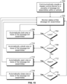
- FIG 13 illustrates a block diagram of a stowage bin control method.
- the method begins at 700, at which the master control device 501 is communicatively coupled to a plurality of stowage bin assemblies 502.
- the master stowage bin control unit 514 of the master control device 501 is in communication with the stowage bin control units 508 of the stowage bin assemblies, such as through wireless communication.
- the master control device 501 monitors status of the stowage bin assemblies 502.
- the master stowage bin control unit 514 receives signals output from the stowage bin assemblies 502 (such as via the stowage bin control units 508) to determine whether the latches 506 are locked or unlocked, the stowage bin assemblies 502 are open or closed, the capacity of the stowage bin assemblies 502, and/or the like.
- the master control stowage bin control unit 514 determined whether one or more of the stowage bin assemblies 704 should be locked. For example, flight personnel may input a locking command into the master stowage bin control unit 514, or the master stowage bin control unit 514 may detect a condition (such as during a particular restricted phase of a flight) that triggers a locking command. If the stowage bin assemblies are to be locked, the master stowage bin control unit 514 outputs a lock command signal that automatically locks one or more of the stowage bin assemblies 502 at 706. The method then returns to 702.
- the method proceeds to 708, at which the master stowage bin control unit 514 determines whether the stowage bin assemblies are to be unlocked at 708. For example, flight personnel may input an unlocking command into the master stowage bin control unit 514, or the master stowage bin control unit 514 may detect a condition that triggers an unlocking command (such as after an aircraft has parked at a gate).
- the method proceeds to 710, at which the master stowage bin control unit 514 automatically unlocks one or more of the stowage bin assemblies 502. The method then returns to 702.
- the method proceeds to 712, at which the master stowage bin control unit 514 determines whether the stowage bin assemblies 502 are to be automatically opened, such as when an aircraft is parked at a gate. If the stowage bin assemblies 502 are to be opened, the method proceeds to 714, at which the master stowage bin control unit 514 automatically opens one or more of the stowage bin assemblies 502. The method then returns to 702.
- the method proceeds to 716, at which the master stowage bin control unit 514 determines whether the stowage bin assemblies 502 are to be automatically closed, such as when an aircraft is taxiing to a runway in order to takeoff. If the stowage bin assemblies 502 are to be closed, the method proceeds to 718, at which the master stowage bin control unit 514 automatically closes one or more of the stowage bin assemblies 502. The method then returns to 702. If, however, the stowage bin assemblies 502 are not to be closed, the method returns to 702.
- Steps 704, 708, 712, and 716 may occur in a different order than shown.
- the master stowage bin control unit 502 may analyze steps 704, 708, 712, and 716 concurrently.
Landscapes
- Engineering & Computer Science (AREA)
- Aviation & Aerospace Engineering (AREA)
- Mechanical Engineering (AREA)
- Vehicle Step Arrangements And Article Storage (AREA)
- Passenger Equipment (AREA)
- Fittings On The Vehicle Exterior For Carrying Loads, And Devices For Holding Or Mounting Articles (AREA)
- Arrangements Of Lighting Devices For Vehicle Interiors, Mounting And Supporting Thereof, Circuits Therefore (AREA)
- Lock And Its Accessories (AREA)
Claims (14)
- Verkehrsmittel mit:einer Innenkabine (30); undeiner Gepäckfachanordnung (502) in der Innenkabine (30), wobei die Gepäckfachanordnung (502) eine Gepäckfachsteuereinheit (508) und ein oder mehrere innenliegende Leuchtelemente umfasst, die konfiguriert sind, um eine Gepäckaufnahmekammer der Gepäckfachanordnung (502) zu beleuchten, und wobei die Gepäckfachsteuereinheit (508) mit den ein oder mehreren innenliegenden Leuchtelementen in Verbindung steht und die Gepäckfachsteuereinheit (508) konfiguriert ist, um die ein oder mehreren innenliegenden Leuchtelemente zu betreiben; wobei:die Gepäckfachanordnung (502) ferner einen Gewichtssensor (532) umfasst, der konfiguriert ist, um das Gewicht der Gepäckfachanordnung (502) und/oder jeglichen in der Gepäckfachanordnung (502) platzierten Gepäcks zu erfassen;die Gepäckfachanordnung (502) konfiguriert ist, um zu bestimmen, ob basierend auf dem erfassten Gewicht in der Gepäckfachanordnung (502) Platz für weiteres Gepäck ist, oder ob basierend auf dem erfassten Gewicht die Gepäckfachanordnung (502) überladen ist; unddie innenliegenden Leuchtelemente (528) konfiguriert sind, um in Verbindung mit der Gepäckfachsteuereinheit (508) und in Verbindung mit dem Gewichtssensor (532) zu arbeiten, um anzuzeigen, ob in der Gepäckfachanordnung (502) Platz für weiteres Gepäck ist, ob die Gepäckfachanordnung (502) voll ist oder ob die Gepäckfachanordnung (502) überladen ist.
- Verkehrsmittel nach Anspruch 1, bei dem die innenliegenden Leuchtelemente (528) konfiguriert sind, um durch Blinken oder Blitzen anzuzeigen, dass die Gepäckfachanordnung (502) überladen ist.
- Verkehrsmittel nach Anspruch 1 oder 2, bei dem die ein oder mehreren innenliegenden Leuchtelemente innerhalb der Gepäckaufnahmekammer der Gepäckfachanordnung (502) angeordnet sind.
- Verkehrsmittel nach einem der Ansprüche 1 - 3, bei dem die innenliegenden Leuchtelemente (528) konfiguriert sind, um im Betrieb durch Leuchten anzuzeigen, dass in der Gepäckfachanordnung (502) Platz für weiteres Gepäck vorhanden ist, und durch Nichtleuchten anzuzeigen, dass in der Gepäckfachanordnung (502) kein Platz für weiteres Gepäck vorhanden ist.
- Verkehrsmittel nach einem der Ansprüche 1 - 3, bei dem die innenliegenden Leuchtelemente (528) konfiguriert sind, um im Betrieb anzuzeigen, dass in der Gepäckfachanordnung (502) Platz für weiteres Gepäck vorhanden ist, indem sie betrieben werden, um grün zu leuchten, und anzuzeigen, dass in der Gepäckfachanordnung (502) kein Platz für weiteres Gepäck vorhanden ist, indem sie betrieben werden, um rot zu leuchten.
- Verkehrsmittel nach einem der Ansprüche 1 - 5, bei dem die ein oder mehreren innenliegenden Leuchtelemente konfiguriert sind, um die Gepäckaufnahmekammer zu beleuchten, wenn sich die Gepäckfachanordnung (502) in einer offenen Stellung befindet, und bei dem die ein oder mehreren innenliegenden Leuchtelemente deaktiviert sind, wenn sich die Gepäckfachanordnung (502) in einer geschlossenen Stellung befindet.
- Verkehrsmittel nach einem der Ansprüche 1 - 6, bei dem die ein oder mehreren innenliegenden Leuchtelemente Licht emittieren, das sich allmählich verstärkt, wenn die Gepäckfachanordnung (502) geöffnet wird, und bei dem die ein oder mehreren innenliegenden Leuchtelemente Licht emittieren, das allmählich erlischt, wenn die Gepäckfachanordnung (502) geschlossen wird.
- Verkehrsmittel nach einem der Ansprüche 1 - 7, bei dem die Gepäckfachanordnung (502) ferner eine Wanne mit einer vorderen Platte umfasst, die mit einer vorderen Endplatte und einer hinteren Endplatte verbunden ist, und bei dem eine Gepäckaufnahmekammer zumindest teilweise zwischen der vorderen Platte, der vorderen Endplatte und der hinteren Platte definiert ist.
- Verkehrsmittel nach Anspruch 8, bei dem die vordere Platte eine bogenförmige Platte mit einer gekrümmten Außenfläche umfasst.
- Verkehrsmittel nach einem der Ansprüche 1 - 9, bei dem die Gepäckfachanordnung (502) ferner ein oder mehrere außenliegende Leuchtelemente umfasst.
- Verkehrsmittel nach Anspruch 10, bei dem die ein oder mehreren außenliegenden Leuchtelemente konfiguriert sind, Licht zu emittieren, um einen aktuellen Status der Gepäckfachanordnung (502) anzuzeigen.
- Verkehrsmittel nach einem der vorhergehenden Ansprüche, wobei das Verkehrsmittel ein Flugzeug ist.
- Verfahren zum Betreiben einer Gepäckfachanordnung (502) in einer Innenkabine (30) eines Verkehrsmittels, wobei das Verfahren umfasst:Verwenden eines Gewichtssensors (532), um das Gewicht der Gepäckfachanordnung (502) und/oder jeglichen Gepäcks, das sich in der Gepäckfachanordnung (502) befindet, zu erfassen;Bestimmen, ob in der Gepäckfachanordnung (502) Platz für weiteres Gepäck vorhanden ist, basierend auf dem erfassten Gewicht, oder ob die Gepäckfachanordnung (502) voll oder überladen ist, basierend auf dem durch den Gewichtssensor (532) erfassten Gewicht; undVerwenden einer Gepäckfachsteuereinheit (508), um eine Gepäckaufnahmekammer der Gepäckfachanordnung (502) mit einem oder mehreren innenliegenden Leuchtelementen zu beleuchten, wobei das Beleuchten das Aussenden von Licht in der Weise umfasst, dass die innenliegenden Leuchtelemente (528) einen Status der Gepäckfachanordnung (502) durch Aussenden von Licht in der Weise anzeigen, dass die innenliegenden Leuchtelemente (528) anzeigen, ob in der Gepäckfachanordnung (502) Platz für weiteres Gepäck ist, ob die Gepäckfachanordnung (502) voll ist oder ob die Gepäckfachanordnung (502) überladen ist, basierend auf dem von dem Gewichtssensor (532) erfassten Gewicht.
- Verfahren nach Anspruch 13, wobei das Beleuchten umfasst:
Aussenden von Licht, so dass die innenliegenden Leuchtelemente (528) entweder: (a) anzeigen, dass in der Gepäckfachanordnung (502) Platz für weiteres Gepäck vorhanden ist, indem sie leuchten, und anzeigen, dass in der Gepäckfachanordnung (502) kein Platz für weiteres Gepäck vorhanden ist, indem sie nicht leuchten; oder (b) anzeigen, dass in der Gepäckfachanordnung (502) Platz für weiteres Gepäck vorhanden ist, indem sie betrieben werden, um grün zu leuchten, und anzeigen, dass in der Gepäckfachanordnung (502) kein Platz für weiteres Gepäck vorhanden ist, indem sie betrieben werden, um rot zu leuchten.
Applications Claiming Priority (2)
| Application Number | Priority Date | Filing Date | Title |
|---|---|---|---|
| US201762469600P | 2017-03-10 | 2017-03-10 | |
| US15/623,611 US10864849B2 (en) | 2017-03-10 | 2017-06-15 | Illuminated stowage bin assemblies within vehicles |
Publications (2)
| Publication Number | Publication Date |
|---|---|
| EP3372504A1 EP3372504A1 (de) | 2018-09-12 |
| EP3372504B1 true EP3372504B1 (de) | 2023-10-18 |
Family
ID=61616837
Family Applications (1)
| Application Number | Title | Priority Date | Filing Date |
|---|---|---|---|
| EP18160758.1A Active EP3372504B1 (de) | 2017-03-10 | 2018-03-08 | Beleuchtete staufächer in fahrzeugen |
Country Status (6)
| Country | Link |
|---|---|
| US (1) | US10864849B2 (de) |
| EP (1) | EP3372504B1 (de) |
| JP (1) | JP7658709B2 (de) |
| CN (1) | CN108569406B (de) |
| BR (1) | BR102018004703B1 (de) |
| CA (1) | CA2996557C (de) |
Families Citing this family (9)
| Publication number | Priority date | Publication date | Assignee | Title |
|---|---|---|---|---|
| US10672208B2 (en) * | 2017-03-10 | 2020-06-02 | The Boeing Company | Touch-free operable stowage bin assemblies |
| US10793277B2 (en) | 2017-03-10 | 2020-10-06 | The Boeing Company | Electronic stowage bin control systems and methods |
| US10906458B2 (en) | 2017-03-10 | 2021-02-02 | The Boeing Company | Vehicles including electronic stowage bin control systems |
| US10647429B2 (en) * | 2017-03-10 | 2020-05-12 | The Boeing Company | Vehicle stowage bin assemblies having weight sensors |
| US10864849B2 (en) | 2017-03-10 | 2020-12-15 | The Boeing Company | Illuminated stowage bin assemblies within vehicles |
| EP3875370B1 (de) * | 2020-03-05 | 2025-12-17 | B/E Aerospace, Inc. | Überkopfgepäckablage mit elektronischem steuerungssystem |
| US20210380250A1 (en) * | 2020-06-05 | 2021-12-09 | B/E Aerospace, Inc. | Wireless overhead bins |
| US12133926B2 (en) * | 2020-06-23 | 2024-11-05 | The Boeing Company | Sanitizing system |
| EP3941168A1 (de) * | 2020-07-14 | 2022-01-19 | ZKW Group GmbH | Fahrzeugmodul mit einer manipulationserkennenden elektronischen steuereinheit |
Citations (1)
| Publication number | Priority date | Publication date | Assignee | Title |
|---|---|---|---|---|
| EP3173329A1 (de) * | 2015-11-26 | 2017-05-31 | Goodrich Corporation | Flugzeuggepäckfachüberwachung und -warnsystem |
Family Cites Families (54)
| Publication number | Priority date | Publication date | Assignee | Title |
|---|---|---|---|---|
| DE3630408A1 (de) * | 1986-09-06 | 1988-03-17 | Iveco Magirus | Gepaeckablage fuer fahrzeuge, insbesondere autobusse |
| US5576931A (en) | 1994-05-03 | 1996-11-19 | The Panda Project | Computer with two fans and two air circulation areas |
| DE19654802C1 (de) * | 1996-12-31 | 1998-07-23 | Sarnatech Paulmann & Crone | Anordnung zur Beleuchtung eines mit einer Verschlußklappe versehenen Ablagefaches |
| US6089588A (en) * | 1998-10-02 | 2000-07-18 | Purkey's Fleet Electrics, Inc. | Apparatus and method for controlling power to interior trailer functions of a heavy duty vehicle |
| JP2002041152A (ja) * | 2000-07-26 | 2002-02-08 | Denso Corp | 電気負荷制御装置 |
| DE20016406U1 (de) * | 2000-09-20 | 2002-02-14 | HYMER-LEICHTMETALLBAU GMBH & CO. KG, 88239 Wangen | Haltegriff für Fahrzeuge aller Art |
| US20020184497A1 (en) | 2000-12-28 | 2002-12-05 | Gage Michael J. | Automated multi-user package retrieval and storage system |
| JP2003291640A (ja) * | 2002-04-05 | 2003-10-15 | Fuji Heavy Ind Ltd | 自動車のボディ制御システム |
| JP2004239008A (ja) | 2003-02-07 | 2004-08-26 | Furukawa Electric Co Ltd:The | アウトサイドハンドル装置及びこれに用いるコネクタ |
| US6945581B2 (en) * | 2003-12-08 | 2005-09-20 | Lear Corporation | Integral lighting for consoles |
| DE102004053140B4 (de) | 2004-11-03 | 2008-12-11 | Airbus Deutschland Gmbh | Gepäckfach, Verfahren zum Herstellen eines Gepäckfachs und Verwendung eines Gepäckfachs in einer Personenbeförderungsvorrichtung |
| US20070133217A1 (en) * | 2005-12-13 | 2007-06-14 | Lear Corporation | Modular storage bin for vehicle |
| FR2899199B1 (fr) * | 2006-03-30 | 2009-02-27 | Airbus Sas | Compartiment a bagages, notamment compartiment clos pour cabine d'aeronef |
| US7887008B2 (en) * | 2006-08-25 | 2011-02-15 | The Boeing Company | System and method for a power-assisted compartment |
| US7893645B2 (en) | 2006-08-25 | 2011-02-22 | The Boeing Company | System and method for compartment control |
| US7937169B2 (en) | 2006-08-25 | 2011-05-03 | The Boeing Company | System and method for compartment control |
| US20080078871A1 (en) | 2006-08-25 | 2008-04-03 | The Boeing Company | System and method for electronically latching compartments |
| US7723935B2 (en) | 2006-08-25 | 2010-05-25 | The Boeing Company | System and method for compartment control |
| US20080055836A1 (en) * | 2006-08-25 | 2008-03-06 | The Boeing Company | System and method for compartment control |
| WO2008058194A2 (en) * | 2006-11-07 | 2008-05-15 | Collins & Aikman Products Co. | Luminous interior trim material |
| US8006903B2 (en) | 2007-12-28 | 2011-08-30 | Mckesson Automation, Inc. | Proximity-based inventory management system using RFID tags to aid in dispensing and restocking inventory |
| US20090178427A1 (en) | 2008-01-10 | 2009-07-16 | Electrolux Home Products, Inc. | Wine cooler with internal lighting |
| US20110199182A1 (en) | 2008-10-08 | 2011-08-18 | Johnson Controls Technology Company | Sensor actuated storage compartment |
| JP2013510764A (ja) * | 2009-11-10 | 2013-03-28 | ジョンソン コントロールズ テクノロジー カンパニー | インテリア用車両コンポーネント内における低プロファイルのスイッチと照明の一体化 |
| US20110253836A1 (en) * | 2010-04-20 | 2011-10-20 | Be Intellectual Property, Inc. | Aircraft bin module with integrated air ducts and lighting |
| US8665119B2 (en) | 2010-04-20 | 2014-03-04 | Be Intellectual Property, Inc. | Electrically activated latch for aircraft stowage bins |
| EP2492194B1 (de) * | 2011-02-24 | 2014-06-04 | Thk Co., Ltd. | Überkopf-Gepäckfach |
| US9938015B2 (en) * | 2011-04-04 | 2018-04-10 | C&D Zodiac, Inc. | Shared entrance seating arrangement |
| US9365291B2 (en) * | 2012-02-14 | 2016-06-14 | C&D Zodiac, Inc. | Passenger service unit pod assembly |
| US8657231B2 (en) | 2012-03-07 | 2014-02-25 | Heath Tecna Inc. | Aircraft cabin bin retrofit |
| DE102012005917B4 (de) | 2012-03-26 | 2016-10-20 | Diehl Aerospace Gmbh | Gepäckablagefach, Flugzeug mit einem Gepäckablagefach sowie Verfahren zum Betreiben des Gepäckablagefachs |
| US20130290221A1 (en) | 2012-04-25 | 2013-10-31 | Satish Jindel | Passenger aircraft overhead bin system and method |
| JP6245724B2 (ja) * | 2012-09-05 | 2017-12-13 | 三菱重工業株式会社 | 照明装置及び機体 |
| AT513939A1 (de) * | 2013-02-01 | 2014-08-15 | Facc Ag | Überkopf-Gepäckfach für Flugzeuge und Flugzeug mit solchen Überkopf-Gepäckfächern |
| US9802553B2 (en) * | 2013-08-12 | 2017-10-31 | Nissan North America, Inc. | Vehicle body structure |
| US9327834B2 (en) * | 2013-10-04 | 2016-05-03 | Embraer S.A. | Overhead bin system |
| US10041650B2 (en) * | 2013-11-21 | 2018-08-07 | Ford Global Technologies, Llc | Illuminated instrument panel storage compartment |
| US9434302B2 (en) * | 2013-11-21 | 2016-09-06 | Ford Global Technologies,Llc | Photoluminescent bin lamp |
| DE102014114915A1 (de) | 2014-10-14 | 2016-04-14 | Airbus Operations Gmbh | Überkopf-Gepäckablagefach mit Formgedächtnisaktuator |
| US20160109280A1 (en) * | 2014-10-15 | 2016-04-21 | The Boeing Company | Smart aircraft overhead luggage bin system |
| US20160138301A1 (en) | 2014-11-14 | 2016-05-19 | The Boeing Company | Self-contained electronic stowage bin system |
| US20160189498A1 (en) | 2014-12-24 | 2016-06-30 | EXILANT Technologies Pvt. Ltd. | Internet of things locker |
| JP6473966B2 (ja) * | 2015-02-12 | 2019-02-27 | パナソニックIpマネジメント株式会社 | 照明装置および移動体 |
| DE102016101321A1 (de) * | 2015-02-12 | 2016-08-18 | Panasonic Intellectual Property Management Co., Ltd. | Leuchteinrichtung, Leuchtsystem und Bewegungsobjekt |
| US9738386B2 (en) * | 2015-04-09 | 2017-08-22 | The Boeing Company | Overhead stowage bin assembly for a vehicle |
| US9908626B2 (en) | 2015-04-10 | 2018-03-06 | Thales Avionics, Inc. | Controlling in flight entertainment system using pointing device integrated into seat |
| US9764842B2 (en) * | 2015-05-11 | 2017-09-19 | The Boeing Company | Storage capacity status indicator and associated systems and methods |
| AT15105U1 (de) * | 2016-02-01 | 2017-01-15 | Facc Ag | Einrichtungsgegenstand, insbesondere für Flugzeuge |
| US10874240B2 (en) | 2016-10-04 | 2020-12-29 | Walmart Apollo, Llc | Landing pad receptacle for package delivery and receipt |
| US10647429B2 (en) | 2017-03-10 | 2020-05-12 | The Boeing Company | Vehicle stowage bin assemblies having weight sensors |
| US10906458B2 (en) | 2017-03-10 | 2021-02-02 | The Boeing Company | Vehicles including electronic stowage bin control systems |
| US10864849B2 (en) | 2017-03-10 | 2020-12-15 | The Boeing Company | Illuminated stowage bin assemblies within vehicles |
| US10793277B2 (en) | 2017-03-10 | 2020-10-06 | The Boeing Company | Electronic stowage bin control systems and methods |
| US10672208B2 (en) | 2017-03-10 | 2020-06-02 | The Boeing Company | Touch-free operable stowage bin assemblies |
-
2017
- 2017-06-15 US US15/623,611 patent/US10864849B2/en active Active
-
2018
- 2018-02-26 CA CA2996557A patent/CA2996557C/en active Active
- 2018-03-07 CN CN201810188803.2A patent/CN108569406B/zh active Active
- 2018-03-07 JP JP2018040356A patent/JP7658709B2/ja active Active
- 2018-03-08 EP EP18160758.1A patent/EP3372504B1/de active Active
- 2018-03-09 BR BR102018004703-5A patent/BR102018004703B1/pt active IP Right Grant
Patent Citations (1)
| Publication number | Priority date | Publication date | Assignee | Title |
|---|---|---|---|---|
| EP3173329A1 (de) * | 2015-11-26 | 2017-05-31 | Goodrich Corporation | Flugzeuggepäckfachüberwachung und -warnsystem |
Also Published As
| Publication number | Publication date |
|---|---|
| US10864849B2 (en) | 2020-12-15 |
| CN108569406B (zh) | 2023-06-16 |
| JP2018197099A (ja) | 2018-12-13 |
| JP7658709B2 (ja) | 2025-04-08 |
| CN108569406A (zh) | 2018-09-25 |
| BR102018004703B1 (pt) | 2023-11-21 |
| BR102018004703A2 (pt) | 2018-10-30 |
| CA2996557C (en) | 2023-04-25 |
| CA2996557A1 (en) | 2018-09-10 |
| EP3372504A1 (de) | 2018-09-12 |
| US20180257555A1 (en) | 2018-09-13 |
Similar Documents
| Publication | Publication Date | Title |
|---|---|---|
| EP3372501B1 (de) | Elektronische systeme zur steuerung von gepäckfächern und verfahren | |
| EP3372503B1 (de) | Berührungslos bedienbare gepäckfachanordnungen | |
| EP3372502B1 (de) | Fahrzeuge mit elektronischen gepäckfachsteuerungssystemen | |
| EP3372505B1 (de) | Fahrzeuggepäckfachanordnungen mit gewichtssensoren | |
| EP3372504B1 (de) | Beleuchtete staufächer in fahrzeugen | |
| BR102018004695B1 (pt) | Sistema de controle de compartimento de armazenamento para um veículo, veículo e método para operar um sistema de controle de compartimento de armazenamento |
Legal Events
| Date | Code | Title | Description |
|---|---|---|---|
| PUAI | Public reference made under article 153(3) epc to a published international application that has entered the european phase |
Free format text: ORIGINAL CODE: 0009012 |
|
| STAA | Information on the status of an ep patent application or granted ep patent |
Free format text: STATUS: REQUEST FOR EXAMINATION WAS MADE |
|
| 17P | Request for examination filed |
Effective date: 20180308 |
|
| AK | Designated contracting states |
Kind code of ref document: A1 Designated state(s): AL AT BE BG CH CY CZ DE DK EE ES FI FR GB GR HR HU IE IS IT LI LT LU LV MC MK MT NL NO PL PT RO RS SE SI SK SM TR |
|
| AX | Request for extension of the european patent |
Extension state: BA ME |
|
| STAA | Information on the status of an ep patent application or granted ep patent |
Free format text: STATUS: EXAMINATION IS IN PROGRESS |
|
| 17Q | First examination report despatched |
Effective date: 20200220 |
|
| RAP3 | Party data changed (applicant data changed or rights of an application transferred) |
Owner name: THE BOEING COMPANY |
|
| GRAP | Despatch of communication of intention to grant a patent |
Free format text: ORIGINAL CODE: EPIDOSNIGR1 |
|
| STAA | Information on the status of an ep patent application or granted ep patent |
Free format text: STATUS: GRANT OF PATENT IS INTENDED |
|
| INTG | Intention to grant announced |
Effective date: 20230511 |
|
| P01 | Opt-out of the competence of the unified patent court (upc) registered |
Effective date: 20230612 |
|
| GRAS | Grant fee paid |
Free format text: ORIGINAL CODE: EPIDOSNIGR3 |
|
| GRAA | (expected) grant |
Free format text: ORIGINAL CODE: 0009210 |
|
| STAA | Information on the status of an ep patent application or granted ep patent |
Free format text: STATUS: THE PATENT HAS BEEN GRANTED |
|
| AK | Designated contracting states |
Kind code of ref document: B1 Designated state(s): AL AT BE BG CH CY CZ DE DK EE ES FI FR GB GR HR HU IE IS IT LI LT LU LV MC MK MT NL NO PL PT RO RS SE SI SK SM TR |
|
| REG | Reference to a national code |
Ref country code: GB Ref legal event code: FG4D |
|
| REG | Reference to a national code |
Ref country code: CH Ref legal event code: EP |
|
| REG | Reference to a national code |
Ref country code: DE Ref legal event code: R096 Ref document number: 602018059463 Country of ref document: DE |
|
| REG | Reference to a national code |
Ref country code: IE Ref legal event code: FG4D |
|
| REG | Reference to a national code |
Ref country code: LT Ref legal event code: MG9D |
|
| REG | Reference to a national code |
Ref country code: NL Ref legal event code: MP Effective date: 20231018 |
|
| REG | Reference to a national code |
Ref country code: AT Ref legal event code: MK05 Ref document number: 1622236 Country of ref document: AT Kind code of ref document: T Effective date: 20231018 |
|
| PG25 | Lapsed in a contracting state [announced via postgrant information from national office to epo] |
Ref country code: NL Free format text: LAPSE BECAUSE OF FAILURE TO SUBMIT A TRANSLATION OF THE DESCRIPTION OR TO PAY THE FEE WITHIN THE PRESCRIBED TIME-LIMIT Effective date: 20231018 |
|
| PG25 | Lapsed in a contracting state [announced via postgrant information from national office to epo] |
Ref country code: GR Free format text: LAPSE BECAUSE OF FAILURE TO SUBMIT A TRANSLATION OF THE DESCRIPTION OR TO PAY THE FEE WITHIN THE PRESCRIBED TIME-LIMIT Effective date: 20240119 |
|
| PG25 | Lapsed in a contracting state [announced via postgrant information from national office to epo] |
Ref country code: IS Free format text: LAPSE BECAUSE OF FAILURE TO SUBMIT A TRANSLATION OF THE DESCRIPTION OR TO PAY THE FEE WITHIN THE PRESCRIBED TIME-LIMIT Effective date: 20240218 |
|
| PG25 | Lapsed in a contracting state [announced via postgrant information from national office to epo] |
Ref country code: LT Free format text: LAPSE BECAUSE OF FAILURE TO SUBMIT A TRANSLATION OF THE DESCRIPTION OR TO PAY THE FEE WITHIN THE PRESCRIBED TIME-LIMIT Effective date: 20231018 |
|
| PG25 | Lapsed in a contracting state [announced via postgrant information from national office to epo] |
Ref country code: AT Free format text: LAPSE BECAUSE OF FAILURE TO SUBMIT A TRANSLATION OF THE DESCRIPTION OR TO PAY THE FEE WITHIN THE PRESCRIBED TIME-LIMIT Effective date: 20231018 |
|
| PG25 | Lapsed in a contracting state [announced via postgrant information from national office to epo] |
Ref country code: ES Free format text: LAPSE BECAUSE OF FAILURE TO SUBMIT A TRANSLATION OF THE DESCRIPTION OR TO PAY THE FEE WITHIN THE PRESCRIBED TIME-LIMIT Effective date: 20231018 |
|
| PG25 | Lapsed in a contracting state [announced via postgrant information from national office to epo] |
Ref country code: LT Free format text: LAPSE BECAUSE OF FAILURE TO SUBMIT A TRANSLATION OF THE DESCRIPTION OR TO PAY THE FEE WITHIN THE PRESCRIBED TIME-LIMIT Effective date: 20231018 Ref country code: IS Free format text: LAPSE BECAUSE OF FAILURE TO SUBMIT A TRANSLATION OF THE DESCRIPTION OR TO PAY THE FEE WITHIN THE PRESCRIBED TIME-LIMIT Effective date: 20240218 Ref country code: GR Free format text: LAPSE BECAUSE OF FAILURE TO SUBMIT A TRANSLATION OF THE DESCRIPTION OR TO PAY THE FEE WITHIN THE PRESCRIBED TIME-LIMIT Effective date: 20240119 Ref country code: ES Free format text: LAPSE BECAUSE OF FAILURE TO SUBMIT A TRANSLATION OF THE DESCRIPTION OR TO PAY THE FEE WITHIN THE PRESCRIBED TIME-LIMIT Effective date: 20231018 Ref country code: BG Free format text: LAPSE BECAUSE OF FAILURE TO SUBMIT A TRANSLATION OF THE DESCRIPTION OR TO PAY THE FEE WITHIN THE PRESCRIBED TIME-LIMIT Effective date: 20240118 Ref country code: AT Free format text: LAPSE BECAUSE OF FAILURE TO SUBMIT A TRANSLATION OF THE DESCRIPTION OR TO PAY THE FEE WITHIN THE PRESCRIBED TIME-LIMIT Effective date: 20231018 Ref country code: PT Free format text: LAPSE BECAUSE OF FAILURE TO SUBMIT A TRANSLATION OF THE DESCRIPTION OR TO PAY THE FEE WITHIN THE PRESCRIBED TIME-LIMIT Effective date: 20240219 |
|
| PG25 | Lapsed in a contracting state [announced via postgrant information from national office to epo] |
Ref country code: SE Free format text: LAPSE BECAUSE OF FAILURE TO SUBMIT A TRANSLATION OF THE DESCRIPTION OR TO PAY THE FEE WITHIN THE PRESCRIBED TIME-LIMIT Effective date: 20231018 Ref country code: RS Free format text: LAPSE BECAUSE OF FAILURE TO SUBMIT A TRANSLATION OF THE DESCRIPTION OR TO PAY THE FEE WITHIN THE PRESCRIBED TIME-LIMIT Effective date: 20231018 Ref country code: PL Free format text: LAPSE BECAUSE OF FAILURE TO SUBMIT A TRANSLATION OF THE DESCRIPTION OR TO PAY THE FEE WITHIN THE PRESCRIBED TIME-LIMIT Effective date: 20231018 Ref country code: NO Free format text: LAPSE BECAUSE OF FAILURE TO SUBMIT A TRANSLATION OF THE DESCRIPTION OR TO PAY THE FEE WITHIN THE PRESCRIBED TIME-LIMIT Effective date: 20240118 Ref country code: LV Free format text: LAPSE BECAUSE OF FAILURE TO SUBMIT A TRANSLATION OF THE DESCRIPTION OR TO PAY THE FEE WITHIN THE PRESCRIBED TIME-LIMIT Effective date: 20231018 Ref country code: HR Free format text: LAPSE BECAUSE OF FAILURE TO SUBMIT A TRANSLATION OF THE DESCRIPTION OR TO PAY THE FEE WITHIN THE PRESCRIBED TIME-LIMIT Effective date: 20231018 |
|
| PG25 | Lapsed in a contracting state [announced via postgrant information from national office to epo] |
Ref country code: DK Free format text: LAPSE BECAUSE OF FAILURE TO SUBMIT A TRANSLATION OF THE DESCRIPTION OR TO PAY THE FEE WITHIN THE PRESCRIBED TIME-LIMIT Effective date: 20231018 |
|
| REG | Reference to a national code |
Ref country code: DE Ref legal event code: R097 Ref document number: 602018059463 Country of ref document: DE |
|
| PG25 | Lapsed in a contracting state [announced via postgrant information from national office to epo] |
Ref country code: CZ Free format text: LAPSE BECAUSE OF FAILURE TO SUBMIT A TRANSLATION OF THE DESCRIPTION OR TO PAY THE FEE WITHIN THE PRESCRIBED TIME-LIMIT Effective date: 20231018 |
|
| PG25 | Lapsed in a contracting state [announced via postgrant information from national office to epo] |
Ref country code: SK Free format text: LAPSE BECAUSE OF FAILURE TO SUBMIT A TRANSLATION OF THE DESCRIPTION OR TO PAY THE FEE WITHIN THE PRESCRIBED TIME-LIMIT Effective date: 20231018 |
|
| PG25 | Lapsed in a contracting state [announced via postgrant information from national office to epo] |
Ref country code: SM Free format text: LAPSE BECAUSE OF FAILURE TO SUBMIT A TRANSLATION OF THE DESCRIPTION OR TO PAY THE FEE WITHIN THE PRESCRIBED TIME-LIMIT Effective date: 20231018 Ref country code: SK Free format text: LAPSE BECAUSE OF FAILURE TO SUBMIT A TRANSLATION OF THE DESCRIPTION OR TO PAY THE FEE WITHIN THE PRESCRIBED TIME-LIMIT Effective date: 20231018 Ref country code: RO Free format text: LAPSE BECAUSE OF FAILURE TO SUBMIT A TRANSLATION OF THE DESCRIPTION OR TO PAY THE FEE WITHIN THE PRESCRIBED TIME-LIMIT Effective date: 20231018 Ref country code: IT Free format text: LAPSE BECAUSE OF FAILURE TO SUBMIT A TRANSLATION OF THE DESCRIPTION OR TO PAY THE FEE WITHIN THE PRESCRIBED TIME-LIMIT Effective date: 20231018 Ref country code: EE Free format text: LAPSE BECAUSE OF FAILURE TO SUBMIT A TRANSLATION OF THE DESCRIPTION OR TO PAY THE FEE WITHIN THE PRESCRIBED TIME-LIMIT Effective date: 20231018 Ref country code: DK Free format text: LAPSE BECAUSE OF FAILURE TO SUBMIT A TRANSLATION OF THE DESCRIPTION OR TO PAY THE FEE WITHIN THE PRESCRIBED TIME-LIMIT Effective date: 20231018 Ref country code: CZ Free format text: LAPSE BECAUSE OF FAILURE TO SUBMIT A TRANSLATION OF THE DESCRIPTION OR TO PAY THE FEE WITHIN THE PRESCRIBED TIME-LIMIT Effective date: 20231018 |
|
| PLBE | No opposition filed within time limit |
Free format text: ORIGINAL CODE: 0009261 |
|
| STAA | Information on the status of an ep patent application or granted ep patent |
Free format text: STATUS: NO OPPOSITION FILED WITHIN TIME LIMIT |
|
| 26N | No opposition filed |
Effective date: 20240719 |
|
| PG25 | Lapsed in a contracting state [announced via postgrant information from national office to epo] |
Ref country code: SI Free format text: LAPSE BECAUSE OF FAILURE TO SUBMIT A TRANSLATION OF THE DESCRIPTION OR TO PAY THE FEE WITHIN THE PRESCRIBED TIME-LIMIT Effective date: 20231018 |
|
| PG25 | Lapsed in a contracting state [announced via postgrant information from national office to epo] |
Ref country code: SI Free format text: LAPSE BECAUSE OF FAILURE TO SUBMIT A TRANSLATION OF THE DESCRIPTION OR TO PAY THE FEE WITHIN THE PRESCRIBED TIME-LIMIT Effective date: 20231018 |
|
| REG | Reference to a national code |
Ref country code: CH Ref legal event code: PL |
|
| PG25 | Lapsed in a contracting state [announced via postgrant information from national office to epo] |
Ref country code: LU Free format text: LAPSE BECAUSE OF NON-PAYMENT OF DUE FEES Effective date: 20240308 |
|
| PG25 | Lapsed in a contracting state [announced via postgrant information from national office to epo] |
Ref country code: MC Free format text: LAPSE BECAUSE OF FAILURE TO SUBMIT A TRANSLATION OF THE DESCRIPTION OR TO PAY THE FEE WITHIN THE PRESCRIBED TIME-LIMIT Effective date: 20231018 |
|
| PG25 | Lapsed in a contracting state [announced via postgrant information from national office to epo] |
Ref country code: MC Free format text: LAPSE BECAUSE OF FAILURE TO SUBMIT A TRANSLATION OF THE DESCRIPTION OR TO PAY THE FEE WITHIN THE PRESCRIBED TIME-LIMIT Effective date: 20231018 Ref country code: LU Free format text: LAPSE BECAUSE OF NON-PAYMENT OF DUE FEES Effective date: 20240308 |
|
| REG | Reference to a national code |
Ref country code: BE Ref legal event code: MM Effective date: 20240331 |
|
| PG25 | Lapsed in a contracting state [announced via postgrant information from national office to epo] |
Ref country code: BE Free format text: LAPSE BECAUSE OF NON-PAYMENT OF DUE FEES Effective date: 20240331 |
|
| PG25 | Lapsed in a contracting state [announced via postgrant information from national office to epo] |
Ref country code: IE Free format text: LAPSE BECAUSE OF NON-PAYMENT OF DUE FEES Effective date: 20240308 |
|
| PG25 | Lapsed in a contracting state [announced via postgrant information from national office to epo] |
Ref country code: IE Free format text: LAPSE BECAUSE OF NON-PAYMENT OF DUE FEES Effective date: 20240308 Ref country code: BE Free format text: LAPSE BECAUSE OF NON-PAYMENT OF DUE FEES Effective date: 20240331 Ref country code: CH Free format text: LAPSE BECAUSE OF NON-PAYMENT OF DUE FEES Effective date: 20240331 |
|
| PG25 | Lapsed in a contracting state [announced via postgrant information from national office to epo] |
Ref country code: CY Free format text: LAPSE BECAUSE OF FAILURE TO SUBMIT A TRANSLATION OF THE DESCRIPTION OR TO PAY THE FEE WITHIN THE PRESCRIBED TIME-LIMIT; INVALID AB INITIO Effective date: 20180308 |
|
| PG25 | Lapsed in a contracting state [announced via postgrant information from national office to epo] |
Ref country code: HU Free format text: LAPSE BECAUSE OF FAILURE TO SUBMIT A TRANSLATION OF THE DESCRIPTION OR TO PAY THE FEE WITHIN THE PRESCRIBED TIME-LIMIT; INVALID AB INITIO Effective date: 20180308 |
|
| PG25 | Lapsed in a contracting state [announced via postgrant information from national office to epo] |
Ref country code: FI Free format text: LAPSE BECAUSE OF FAILURE TO SUBMIT A TRANSLATION OF THE DESCRIPTION OR TO PAY THE FEE WITHIN THE PRESCRIBED TIME-LIMIT Effective date: 20231019 |
|
| PG25 | Lapsed in a contracting state [announced via postgrant information from national office to epo] |
Ref country code: TR Free format text: LAPSE BECAUSE OF FAILURE TO SUBMIT A TRANSLATION OF THE DESCRIPTION OR TO PAY THE FEE WITHIN THE PRESCRIBED TIME-LIMIT Effective date: 20231018 |
|
| PGFP | Annual fee paid to national office [announced via postgrant information from national office to epo] |
Ref country code: GB Payment date: 20260327 Year of fee payment: 9 |
|
| PGFP | Annual fee paid to national office [announced via postgrant information from national office to epo] |
Ref country code: DE Payment date: 20260327 Year of fee payment: 9 |
|
| PGFP | Annual fee paid to national office [announced via postgrant information from national office to epo] |
Ref country code: FR Payment date: 20260325 Year of fee payment: 9 |