EP3372453A2 - Steer by wire-system und verfahren zum datenaustausch in einem steer by wire-system - Google Patents
Steer by wire-system und verfahren zum datenaustausch in einem steer by wire-system Download PDFInfo
- Publication number
- EP3372453A2 EP3372453A2 EP18156214.1A EP18156214A EP3372453A2 EP 3372453 A2 EP3372453 A2 EP 3372453A2 EP 18156214 A EP18156214 A EP 18156214A EP 3372453 A2 EP3372453 A2 EP 3372453A2
- Authority
- EP
- European Patent Office
- Prior art keywords
- control device
- control unit
- steer
- bus system
- bus
- Prior art date
- Legal status (The legal status is an assumption and is not a legal conclusion. Google has not performed a legal analysis and makes no representation as to the accuracy of the status listed.)
- Granted
Links
Images
Classifications
-
- B—PERFORMING OPERATIONS; TRANSPORTING
- B62—LAND VEHICLES FOR TRAVELLING OTHERWISE THAN ON RAILS
- B62D—MOTOR VEHICLES; TRAILERS
- B62D6/00—Arrangements for automatically controlling steering depending on driving conditions sensed and responded to, e.g. control circuits
- B62D6/008—Control of feed-back to the steering input member, e.g. simulating road feel in steer-by-wire applications
-
- B—PERFORMING OPERATIONS; TRANSPORTING
- B60—VEHICLES IN GENERAL
- B60R—VEHICLES, VEHICLE FITTINGS, OR VEHICLE PARTS, NOT OTHERWISE PROVIDED FOR
- B60R16/00—Electric or fluid circuits specially adapted for vehicles and not otherwise provided for; Arrangement of elements of electric or fluid circuits specially adapted for vehicles and not otherwise provided for
- B60R16/02—Electric or fluid circuits specially adapted for vehicles and not otherwise provided for; Arrangement of elements of electric or fluid circuits specially adapted for vehicles and not otherwise provided for electric constitutive elements
- B60R16/023—Electric or fluid circuits specially adapted for vehicles and not otherwise provided for; Arrangement of elements of electric or fluid circuits specially adapted for vehicles and not otherwise provided for electric constitutive elements for transmission of signals between vehicle parts or subsystems
- B60R16/0231—Circuits relating to the driving or the functioning of the vehicle
-
- B—PERFORMING OPERATIONS; TRANSPORTING
- B62—LAND VEHICLES FOR TRAVELLING OTHERWISE THAN ON RAILS
- B62D—MOTOR VEHICLES; TRAILERS
- B62D15/00—Steering not otherwise provided for
- B62D15/02—Steering position indicators ; Steering position determination; Steering aids
- B62D15/021—Determination of steering angle
-
- B—PERFORMING OPERATIONS; TRANSPORTING
- B62—LAND VEHICLES FOR TRAVELLING OTHERWISE THAN ON RAILS
- B62D—MOTOR VEHICLES; TRAILERS
- B62D5/00—Power-assisted or power-driven steering
- B62D5/001—Mechanical components or aspects of steer-by-wire systems, not otherwise provided for in this maingroup
-
- B—PERFORMING OPERATIONS; TRANSPORTING
- B62—LAND VEHICLES FOR TRAVELLING OTHERWISE THAN ON RAILS
- B62D—MOTOR VEHICLES; TRAILERS
- B62D5/00—Power-assisted or power-driven steering
- B62D5/04—Power-assisted or power-driven steering electrical, e.g. using an electric servo-motor connected to, or forming part of, the steering gear
- B62D5/0457—Power-assisted or power-driven steering electrical, e.g. using an electric servo-motor connected to, or forming part of, the steering gear characterised by control features of the drive means as such
-
- B—PERFORMING OPERATIONS; TRANSPORTING
- B62—LAND VEHICLES FOR TRAVELLING OTHERWISE THAN ON RAILS
- B62D—MOTOR VEHICLES; TRAILERS
- B62D5/00—Power-assisted or power-driven steering
- B62D5/04—Power-assisted or power-driven steering electrical, e.g. using an electric servo-motor connected to, or forming part of, the steering gear
- B62D5/0457—Power-assisted or power-driven steering electrical, e.g. using an electric servo-motor connected to, or forming part of, the steering gear characterised by control features of the drive means as such
- B62D5/046—Controlling the motor
Definitions
- the invention relates to a steer by wire system and a method for data exchange in a steer by wire system.
- Steer by wire systems are characterized in that there is no mechanical operative connection between a steering handle and a steering actuator.
- the steering actuator for example an electric motor
- the electric motor then applies force to a rack, for example, to deflect the wheels.
- a sensor for detecting a steering wheel angle is arranged on the steering handle, such as a steering wheel. This steering wheel angle is transmitted to the first control unit and from this a desired steering angle is determined as the driver's request and converted by the steering actuator.
- This actuator is, for example, an electric motor, which is controlled by a second control unit.
- the systems should be intrinsically safe in terms of networking, for which two independent bus connections are necessary. Since the actuator on the steering handle should preferably also give a haptic feedback of the road or the driving dynamics, a relatively fast data connection from the first controller to the second controller would be desirable. However, this encounters limits in conventional bus systems with many controllers.
- an x-by-wire system for a vehicle comprising at least one sensor for detecting an actuation of an input device, at least one control unit for determining a Sollstell Tan and at least one energy supply, said sensor, control device, control system and power supply each redundantly from first and second modules are composed and the two modules form an assembly.
- the modules of a module are decoupled from each other without feedback, the first modules are networked together and form a first subsystem and the second modules are interconnected and form a second subsystem, wherein at least the second subsystem is formed exclusively of the second modules.
- the communication between the modules preferably takes place via a redundant bus system.
- the invention is based on the technical problem of providing a steer-by-wire system which enables intrinsic safety at high transmission rates at low cost. Another technical problem is to provide a method of data exchange in such a steer by wire system.
- the steer by wire system comprises a first control unit which controls at least one steering actuator, and at least one second control unit which controls at least one actuator on a steering handle in order to generate a haptic torque.
- the second control unit is associated with a sensor for detecting a steering wheel angle.
- the first control unit is connected to a first bus system and the second control unit is connected to a second bus system, wherein the two bus systems are interconnected via a gateway control unit.
- the first and second control units are directly connected to each other via a third bus system.
- the control units are intrinsically safe networked via the two first bus systems, wherein the first and second control units each have to have only one bus interface through the connection via the gateway control unit.
- the time-critical data may then be transmitted by the third bus system, a relatively high data transfer rate being no problem due to the fact that only two controllers communicate.
- the third bus system has a higher data transmission rate than the first and the second bus system.
- the data transfer rate is at least twice as high as the data transfer rate of the first and second bus systems.
- the second control unit is configured to additionally transmit at least the data of the sensor system via the gateway control unit to the first control unit, with at least safety-relevant data being exchanged between the first and second control unit via the third bus system.
- the data of the sensors are transmitted redundantly, namely from the second control unit via the gateway control unit and via the third bus system directly to the first control unit, i. Therefore, even if one bus system fails, data from the sensor system is always available to the first controller.
- At least the first control unit and the steering actuator and the second control unit and the sensors have a redundant Power supply, so that a steering operation is possible even in the event of a power failure.
- the actuator for generating the torque on the steering handle is not safety-relevant, so that a redundancy is unnecessary here, but of course still can be provided.
- the invention will be explained in more detail below with reference to a preferred embodiment.
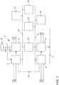
- the single figure shows a schematic block diagram of a steer by wire system.
- the steer by wire system 1 comprises a first control unit 2 and a steering actuator 3, which is designed for example as an electric motor and transmits a force to a rack 4. Furthermore, the steer by wire system 1 comprises a second control unit 5, an actuator 6, a sensor 7 for detecting a steering wheel angle and a steering handle 8. The second control unit 5 controls the actuator 6, wherein this generates a haptic torque on the steering handle 8 , It can be provided that different characteristics are stored in the second control unit 5, so that depending on the ratio between the steering wheel angle and the actual steering angle to the vehicle wheels, a different moment is set to the steering handle 8. In this case, mechanical stops on the steering handle 8 can be simulated.
- the data of the sensor 7 are transmitted to the second control unit 5.
- the first control device 2 is connected to a first bus system 9 and the second control device 5 is connected to a second bus system 10, wherein on the first and second bus system 9, 10 further control devices 11-14 are connected.
- These control units 11-14 are, for example, control units of assistance systems which generate steering requirements (eg lane departure warning) or generate moments on the steering handle (eg vibrations against fatigue).
- control units 11-14 can also be connected to both bus systems 9, 10.
- the first control unit 2 and the second control unit 5 are also connected to each other directly via a third bus system 16.
- the first bus system 9 and the second bus system 10 are, for example, CAN bus systems with a data transmission rate of 500 kbit / s.
- the third bus system 16 is also a CAN bus system with a data transmission rate of 1 Mbit / s. In principle, however, other bus systems than CAN can be used for the first, second and third bus systems.
- the individual components of the steer-by-wire system 1 are furthermore designed with a redundant voltage supply V1, V2, wherein the redundant power supply for the actuator 6 is optional.
- the two control units 2, 5 can now bidirectionally exchange all data via the fast third bus system 16, which are of interest for the respective other control unit 5, 2, in particular also the data of the sensor system 7.
- the data of the sensor 7 from the second control unit 5 transmitted via the second bus system 10 to the gateway control unit 15 and transmitted from there via the first bus system 9 to the first control unit 2, so that the data of the sensor 7 are transmitted redundantly to the first control unit 2.
- the proposed steer by wire system allows fast data transmission between the two control units 2, 5, wherein the networking is intrinsically safe and the data of the sensor 7 are transmitted redundantly, the control units 2, 5 need only have two network interfaces.
Landscapes
- Engineering & Computer Science (AREA)
- Mechanical Engineering (AREA)
- Chemical & Material Sciences (AREA)
- Combustion & Propulsion (AREA)
- Transportation (AREA)
- Automation & Control Theory (AREA)
- Steering Control In Accordance With Driving Conditions (AREA)
- Power Steering Mechanism (AREA)
Abstract
Description
- Die Erfindung betrifft ein Steer by wire-System und ein Verfahren zum Datenaustausch in einem Steer by wire-System.
- Steer by wire-Systeme sind dadurch gekennzeichnet, dass keine mechanische Wirkverbindung zwischen einer Lenkhandhabe und einem Lenk-Aktuator besteht. Der Lenk-Aktuator, beispielsweise ein Elektromotor, wird von einem ersten Steuergerät gesteuert. Der Elektromotor bringt dann beispielsweise eine Kraft auf eine Zahnstange auf, um die Räder auszulenken. An der Lenkhandhabe, beispielsweise einem Lenkrad, ist einen Sensorik zur Erfassung eines Lenkradwinkels angeordnet. Dieser Lenkradwinkel wird dem ersten Steuergerät übermittelt und daraus ein Soll-Lenkwinkel als Fahrerwunsch ermittelt und durch den Lenk-Aktuator umgesetzt. Des Weiteren ist es bekannt, der Lenkhandhabe einen Aktuator zuzuordnen, um ein haptisches Gegen-Moment an der Lenkhandhabe zu erzeugen, damit der Kraftfahrzeugführer ein haptisches Feed-Back auf seine Lenkbewegungen erhält. Dieser Aktuator ist beispielsweise ein Elektromotor, der durch ein zweites Steuergerät angesteuert wird. Dabei sollten die Systeme hinsichtlich der Vernetzung eigensicher ausgebildet sein, wofür zwei unabhängige Busverbindungen notwendig sind. Da der Aktuator an der Lenkhandhabe vorzugsweise auch ein haptisches Feed-Back der Straße bzw. der Fahrdynamik geben soll, wäre eine relativ schnelle Daten-Verbindung vom ersten Steuergerät zum zweiten Steuergerät wünschenswert. Dies stößt aber an Grenzen in üblichen Bussystemen mit vielen Steuergeräten.
- Aus der
DE 101 12 514 A1 ist ein X-by-wire-System für ein Fahrzeug bekannt, umfassend mindestens einen Sensor zur Erfassung einer Betätigung einer Eingabeeinrichtung, mindestens ein Steuergerät zur Ermittlung einer Sollstellwirkung und mindestens eine Energieversorgung, wobei Sensor, Steuergerät, Stellsystem und Energieversorgung jeweils redundant aus ersten und zweiten Modulen zusammengesetzt sind und die zwei Module eine Baugruppe bilden. Dabei sind die Module einer Baugruppe voneinander rückwirkungsfrei entkoppelt, wobei die ersten Module miteinander vernetzt sind und ein erstes Subsystem bilden und die zweiten Module miteinander vernetzt sind und ein zweites Subsystem bilden, wobei mindestens das zweite Subsystem ausschließlich aus den zweiten Modulen gebildet ist. Vorzugsweise findet die Kommunikation zwischen den Modulen über ein redundantes Bussystem statt. - Der Erfindung liegt das technische Problem zugrunde, ein Steer by wire-System zu schaffen, das Eigensicherheit bei hohen Übertragungsraten mit niedrigen Kosten ermöglicht. Ein weiteres technisches Problem ist es, ein Verfahren zum Datenaustausch in einem solchen Steer by wire-System zur Verfügung zu stellen.
- Die Lösung des technischen Problems ergibt sich durch ein Steer by wire-System mit den Merkmalen des Anspruchs 1 sowie ein Verfahren mit den Merkmalen des Anspruchs 4. Weitere vorteilhafte Ausgestaltungen der Erfindung ergeben sich aus den Unteransprüchen.
- Hierzu umfasst das Steer by wire-System ein erstes Steuergerät, das mindestens einen Lenk-Aktuator steuert, und mindestens ein zweites Steuergerät, das mindestens einen Aktuator an einer Lenkhandhabe steuert, um ein haptisches Moment zu erzeugen. Dabei ist dem zweiten Steuergerät eine Sensorik zur Erfassung eines Lenkradwinkels zugeordnet. Das erste Steuergerät ist mit einem ersten Bussystem verbunden und das zweite Steuergerät ist mit einem zweiten Bussystem verbunden, wobei die beiden Bussysteme über ein Gateway-Steuergerät miteinander verbunden sind. Weiter sind das erste und zweite Steuergerät über ein drittes Bussystem direkt miteinander verbunden. Über die beiden ersten Bussysteme sind die Steuergeräte eigensicher vernetzt, wobei durch die Verbindung über das Gateway-Steuergerät die ersten und zweiten Steuergeräte jeweils nur eine Busschnittstelle aufweisen müssen. Die zeitkritischen Daten können dann durch das dritte Bussystem übertragen werden, wobei aufgrund der Tatsache, dass nur zwei Steuergeräte kommunizieren, eine relativ hohe Datenübertragungsrate kein Problem darstellt. Vorzugweise weist daher auch das dritte Bussystem eine höhere Datenübertragungsrate auf als das erste und das zweite Bussystem. Vorzugsweise ist die Datenübertragungsrate mindestens doppelt so hoch wie die Datenübertragungsrate des ersten und des zweiten Bussystems.
- In einer Ausführungsform ist das zweite Steuergerät derart ausgebildet, mindestens die Daten der Sensorik zusätzlich über das Gateway-Steuergerät an das erste Steuergerät zu übermitteln, wobei mindestens sicherheitsrelevante Daten zwischen dem ersten und zweiten Steuergerät über das dritte Bussystem ausgetauscht werden. Dadurch werden die Daten der Sensorik redundant übertragen, nämlich vom zweiten Steuergerät über das Gateway-Steuergerät und über das dritte Bussystem direkt zum ersten Steuergerät, d.h. auch bei Ausfall eines Bussystems liegen daher immer Daten der Sensorik dem ersten Steuergerät vor.
- In einer weiteren Ausführungsform weisen mindestens das erste Steuergerät und der Lenk-Aktuator sowie das zweite Steuergerät und die Sensorik eine redundante Spannungsversorgung auf, sodass auch bei Ausfall einer Spannungsversorgung ein Lenkbetrieb möglich ist. Der Aktuator zur Erzeugung des Moments an der Lenkhandhabe ist nicht sicherheitsrelevant, sodass hier eine Redundanz entbehrlich ist, selbstverständlich aber trotzdem vorgesehen sein kann.
- Die Erfindung wird nachfolgend anhand eines bevorzugten Ausführungsbeispiels näher erläutert. Die einzige Figur zeigt ein schematisches Blockschaltbild eines Steer by wire-Systems.
- In der
Fig. 1 ist ein Blockschaltbild eines Steer by wire-Systems 1 dargestellt. Das Steer by wire-System 1 umfasst ein erstes Steuergerät 2 und einen Lenk-Aktuator 3, der beispielsweise als Elektromotor ausgebildet ist und eine Kraft auf eine Zahnstange 4 überträgt. Weiter umfasst das Steer by wire-System 1 ein zweites Steuergerät 5, einen Aktuator 6, eine Sensorik 7 zur Erfassung eines Lenkradwinkels und eine Lenkhandhabe 8. Das zweite Steuergerät 5 steuert den Aktuator 6 an, wobei dieser ein haptisches Moment an der Lenkhandhabe 8 erzeugt. Dabei kann vorgesehen sein, dass verschiedene Kennlinien in dem zweiten Steuergerät 5 abgelegt sind, sodass je nach Übersetzungsverhältnis zwischen Lenkradwinkel und tatsächlichem Lenkwinkel an den Fahrzeugrädern ein unterschiedliches Moment an der Lenkhandhabe 8 eingestellt wird. Dabei können auch mechanische Endanschläge an der Lenkhandhabe 8 simuliert werden. Die Daten der Sensorik 7 werden an das zweite Steuergerät 5 übermittelt. Das erste Steuergerät 2 ist mit einem ersten Bussystem 9 und das zweite Steuergerät 5 ist mit einem zweiten Bussystem 10 verbunden, wobei an dem ersten und zweiten Bussystem 9, 10 weitere Steuergeräte 11-14 angeschlossen sind. Diese Steuergeräte 11-14 sind beispielsweise Steuergeräte von Assistenz-Systemen, die Lenkanforderungen generieren (z.B. Lane Departure Warning) oder Momente an der Lenkhandhabe generieren (z.B. Vibrationen gegen Müdigkeit). Dabei können Steuergeräte 11-14 auch mit beiden Bussystemen 9, 10 verbunden sein. Dabei existiert mindestens ein Gateway-Steuergerät 15, das mit beiden Bussystemen 9, 10 verbunden ist und Nachrichten von einem Bussystem auf das andere Bussystem routen kann. - Das erste Steuergerät 2 und das zweite Steuergerät 5 sind darüber hinaus direkt über ein drittes Bussystem 16 miteinander verbunden. Das erste Bussystem 9 und das zweite Bussystem 10 sind beispielsweise CAN-Bussysteme mit einer Datenübertragungsrate von 500 kBit/s. Das dritte Bussystem 16 ist beispielsweise auch ein CAN-Bussystem mit einer Datenübertragungsrate von 1 MBit/s. Prinzipiell können aber für das erste, zweite und dritte Bussystem andere Bussysteme als CAN zur Anwendung kommen.
- Die einzelnen Komponenten des Steer by wire-Systems 1 sind darüber hinaus mit einer redundanten Spannungsversorgung V1, V2 ausgebildet, wobei die redundante Spannungsversorgung für den Aktuator 6 optional ist.
- Die beiden Steuergeräte 2, 5 können nun bidirektional alle Daten über das schnelle dritte Bussystem 16 austauschen, die für das jeweils andere Steuergerät 5, 2 von Interesse sind, insbesondere auch die Daten der Sensorik 7. Zusätzlich werden die Daten der Sensorik 7 vom zweiten Steuergerät 5 über das zweite Bussystem 10 an das Gateway-Steuergerät 15 übertragen und von dort über das erste Bussystem 9 an das erste Steuergerät 2 übertragen, sodass die Daten der Sensorik 7 redundant an das erste Steuergerät 2 übertragen werden.
- Das vorgestellte Steer by wire-System erlaubt eine schnelle Datenübertragung zwischen den beiden Steuergeräten 2, 5, wobei die Vernetzung eigensicher ist und die Daten der Sensorik 7 redundant übertragen werden, wobei die Steuergeräte 2, 5 nur zwei Netzwerkschnittstellen aufweisen müssen.
Claims (4)
- Steer by wire-System (1), umfassend ein erstes Steuergerät (2), das mindestens einen Lenk-Aktuator (3) steuert, und mindestens ein zweites Steuergerät (5), das mindestens einen Aktuator (6) an einer Lenkhandhabe (8) steuert, um ein haptisches Moment zu erzeugen, wobei dem zweiten Steuergerät (5) eine Sensorik (7) zur Erfassung eines Lenkradwinkels zugeordnet ist, wobei das erste Steuergerät (2) mit einem ersten Bussystem (9) verbunden ist und das zweite Steuergerät (5) mit einem zweiten Bussystem (10) verbunden ist, wobei die beiden Bussysteme (9, 10) über ein Gateway-Steuergerät (15) miteinander verbunden sind und das erste Steuergerät (2) und das zweite Steuergerät (3) über ein drittes Bussystem (16) direkt miteinander verbunden sind.
- Steer by wire-System nach Anspruch 1, dadurch gekennzeichnet, dass das zweite Steuergerät (2) derart ausgebildet ist, mindestens Daten der Sensorik (7) zusätzlich über das Gateway-Steuergerät (15) an das erste Steuergerät (2) zu übermitteln, wobei mindestens sicherheitsrelevante Daten zwischen dem ersten Steuergerät (2) und dem zweiten Steuergerät (5) über das dritte Bussystem (16) ausgetauscht werden.
- Steer by wire-System nach Anspruch 1 und 2, dadurch gekennzeichnet, dass mindestens das erste Steuergerät (2) und der Lenk-Aktuator (3) sowie das zweite Steuergerät (5) und die Sensorik (7) eine redundante Spannungsversorgung (V1, V2) aufweisen.
- Verfahren zum Datenaustausch in einem Steer by wire-System (1), mittels eines ersten Steuergeräts (2), das mindestens einen Lenk-Aktuator (3) steuert, und mittels eines zweiten Steuergeräts (5), das mindestens einen Aktuator (6) an einer Lenkhandhabe (8) steuert, um ein haptisches Moment zu erzeugen, wobei dem zweiten Steuergerät (5) eine Sensorik (7) zur Erfassung eines Lenkradwinkels zugeordnet ist, wobei das erste Steuergerät (2) mit einem ersten Bussystem (9) verbunden ist und das zweite Steuergerät (5) mit einem zweiten Bussystem (10) verbunden ist, wobei die beiden Bussysteme (9, 10) über ein Gateway-Steuergerät (15) miteinander verbunden sind und das erste Steuergerät (2) und das zweite Steuergerät (5) über ein drittes Bussystem (16) direkt miteinander verbunden sind, wobei mindestens Daten der Sensorik (7) zusätzlich über das Gateway-Steuergerät (15) an das erste Steuergerät (2) übermittelt werden, wobei mindestens sicherheitsrelevante Daten zwischen dem ersten Steuergerät (2) und dem zweiten Steuergerät (5) über das dritte Bussystem (16) ausgetauscht werden.
Applications Claiming Priority (1)
| Application Number | Priority Date | Filing Date | Title |
|---|---|---|---|
| DE102017203748.2A DE102017203748A1 (de) | 2017-03-07 | 2017-03-07 | Steer by wire-System und Verfahren zum Datenaustausch in einem Steer by wire-System |
Publications (3)
| Publication Number | Publication Date |
|---|---|
| EP3372453A2 true EP3372453A2 (de) | 2018-09-12 |
| EP3372453A3 EP3372453A3 (de) | 2018-10-03 |
| EP3372453B1 EP3372453B1 (de) | 2019-08-14 |
Family
ID=61192749
Family Applications (1)
| Application Number | Title | Priority Date | Filing Date |
|---|---|---|---|
| EP18156214.1A Active EP3372453B1 (de) | 2017-03-07 | 2018-02-12 | Steer by wire-system und verfahren zum datenaustausch in einem steer by wire-system |
Country Status (4)
| Country | Link |
|---|---|
| US (1) | US10464599B2 (de) |
| EP (1) | EP3372453B1 (de) |
| CN (1) | CN108569333B (de) |
| DE (1) | DE102017203748A1 (de) |
Cited By (2)
| Publication number | Priority date | Publication date | Assignee | Title |
|---|---|---|---|---|
| DE102021112146A1 (de) | 2021-05-10 | 2022-11-10 | Dr. Ing. H.C. F. Porsche Aktiengesellschaft | Kabelbasiertes Steuersystem zur Steuerung eines Kraftfahrzeugs |
| EP4527702A1 (de) * | 2023-09-21 | 2025-03-26 | HELLA GmbH & Co. KGaA | X-by-wire-kontrollsystem für ein kraftfahrzeug |
Families Citing this family (14)
| Publication number | Priority date | Publication date | Assignee | Title |
|---|---|---|---|---|
| DE102018106872A1 (de) | 2018-03-22 | 2019-09-26 | Thyssenkrupp Ag | Steer-by-Wire Architekturen |
| US10960949B2 (en) * | 2018-10-24 | 2021-03-30 | Honda Motor Co., Ltd. | Vibration sensor on motorcycle for providing reactionary function |
| JP7061055B2 (ja) * | 2018-11-06 | 2022-04-27 | 日立Astemo株式会社 | ステアリング装置 |
| KR102167906B1 (ko) * | 2019-06-20 | 2020-10-20 | 주식회사 만도 | 조향 제어 장치 및 이를 포함하는 조향 보조 시스템 |
| JP7339072B2 (ja) * | 2019-08-30 | 2023-09-05 | トヨタ自動車株式会社 | ネットワークシステム |
| DE102019214720A1 (de) * | 2019-09-26 | 2021-04-01 | Robert Bosch Gmbh | Steuereinrichtung für ein Fahrzeug |
| DE102019007715A1 (de) * | 2019-11-07 | 2021-05-12 | Daimler Ag | Steer by Wire System |
| KR102735499B1 (ko) * | 2020-02-11 | 2024-11-29 | 에이치엘만도 주식회사 | 조향 어시스트 장치 및 방법과, 조향 시스템 |
| DE102020001083A1 (de) * | 2020-02-20 | 2021-08-26 | Man Truck & Bus Se | Sensorvorrichtung zur Umfelderfassung für ein Kraftfahrzeug |
| CN111634326A (zh) * | 2020-05-07 | 2020-09-08 | 中国第一汽车股份有限公司 | 一种冗余线控转向装置、系统架构以及驾驶设备 |
| DE102020205904A1 (de) * | 2020-05-12 | 2021-11-18 | Thyssenkrupp Ag | Steer-by-Wire-Lenksystem für ein Kraftfahrzeug |
| DE102020127661A1 (de) | 2020-10-21 | 2022-04-21 | Audi Aktiengesellschaft | Steer-by-wire-Lenksystem für ein zweispuriges Fahrzeug |
| DE102021205413A1 (de) * | 2021-05-27 | 2022-12-01 | Volkswagen Aktiengesellschaft | Steer-by-Wire-Lenksystem |
| KR102909937B1 (ko) * | 2023-01-12 | 2026-01-08 | 에이치엘만도 주식회사 | 전동식 파워 스티어링 장치 및 이의 동작 방법 |
Family Cites Families (14)
| Publication number | Priority date | Publication date | Assignee | Title |
|---|---|---|---|---|
| US20040026158A1 (en) * | 2000-03-27 | 2004-02-12 | Peter Rieth | Vehicle system and axle guide module for a vehicle steering system |
| ES2250255T3 (es) * | 2000-09-20 | 2006-04-16 | Thyssenkrupp Presta Steertec Gmbh | Nivel de emergencia adicional en caso de averia de los sensores angulares para un sistema de direccion controlada por cable sin conexion de emergencia mecanica/hidraulica y procedimiento para determinar angulo de rotacion del elemento maniobra direccion de una direccion asistida. |
| DE10052343A1 (de) * | 2000-10-21 | 2002-07-11 | Bosch Gmbh Robert | Verfahren zum Steuern eines Steerby-Wire-Lenksystems |
| DE10112514A1 (de) | 2000-12-22 | 2002-06-27 | Volkswagen Ag | X-by-wire-System für ein Fahrzeug |
| DE10135736C1 (de) * | 2001-07-21 | 2003-04-03 | Zf Lenksysteme Gmbh | Verfahren zum Ansteuern einer Kupplung einer Steer-by-Wire-Lenkanlage |
| US7142963B2 (en) * | 2003-01-17 | 2006-11-28 | General Motors Corporation | Driver control input device for drive-by-wire system |
| DE10333281A1 (de) | 2003-07-18 | 2005-02-03 | Zf Lenksysteme Gmbh | Verfahren zur Steuerung einer Schalteinrichtung |
| DE10352494A1 (de) * | 2003-11-11 | 2005-06-09 | Robert Bosch Gmbh | Momentensteller für ein Lenksystem in einem Kraftfahrzeug |
| EP1616746B1 (de) * | 2004-07-15 | 2010-02-24 | Hitachi, Ltd. | Fahrzeugsteuerungsystem |
| US7400065B2 (en) * | 2004-08-24 | 2008-07-15 | Honeywell International Inc. | Electrical power distribution system and method with active load control |
| DE102005029444A1 (de) * | 2005-06-24 | 2006-12-28 | Robert Bosch Gmbh | Vorrichtung zum Unterstützen eines Führens eines Fahrzeugs und Verfahren zum Betreiben der Vorrichtung |
| CN201405922Y (zh) * | 2009-03-13 | 2010-02-17 | 北京工业大学 | 一种汽车线控转向系统 |
| DE102011088020A1 (de) * | 2011-12-08 | 2013-06-13 | Bayerische Motoren Werke Aktiengesellschaft | Kommunikationseinrichtung für ein Kraftfahrzeug |
| CN202716830U (zh) * | 2012-06-28 | 2013-02-06 | 东南(福建)汽车工业有限公司 | 一种汽车整车总线控制系统结构 |
-
2017
- 2017-03-07 DE DE102017203748.2A patent/DE102017203748A1/de not_active Withdrawn
-
2018
- 2018-02-12 EP EP18156214.1A patent/EP3372453B1/de active Active
- 2018-03-02 US US15/910,335 patent/US10464599B2/en active Active
- 2018-03-07 CN CN201810186022.XA patent/CN108569333B/zh active Active
Cited By (3)
| Publication number | Priority date | Publication date | Assignee | Title |
|---|---|---|---|---|
| DE102021112146A1 (de) | 2021-05-10 | 2022-11-10 | Dr. Ing. H.C. F. Porsche Aktiengesellschaft | Kabelbasiertes Steuersystem zur Steuerung eines Kraftfahrzeugs |
| US12195018B2 (en) | 2021-05-10 | 2025-01-14 | Dr. Ing. H.C. F. Porsche Aktiengesellschaft | Wire based control system for controlling a motor vehicle |
| EP4527702A1 (de) * | 2023-09-21 | 2025-03-26 | HELLA GmbH & Co. KGaA | X-by-wire-kontrollsystem für ein kraftfahrzeug |
Also Published As
| Publication number | Publication date |
|---|---|
| EP3372453B1 (de) | 2019-08-14 |
| US10464599B2 (en) | 2019-11-05 |
| CN108569333B (zh) | 2020-12-08 |
| DE102017203748A1 (de) | 2018-09-13 |
| EP3372453A3 (de) | 2018-10-03 |
| CN108569333A (zh) | 2018-09-25 |
| US20180257703A1 (en) | 2018-09-13 |
Similar Documents
| Publication | Publication Date | Title |
|---|---|---|
| EP3372453B1 (de) | Steer by wire-system und verfahren zum datenaustausch in einem steer by wire-system | |
| EP3768574B1 (de) | Steer-by-wire architekturen | |
| EP3810487B1 (de) | Steer-by-wire architekturen mit zweitem lenkwinkelsensor | |
| EP1198366B1 (de) | Steuerungssystem für ein fahrzeug und verfahren zur steuerung eines fahrzeugs | |
| DE112020002938T5 (de) | Lenksteuervorrichtung und lenkunterstützungssystem mit derselben | |
| EP4095016B1 (de) | Steer-by-wire-lenksystem | |
| EP3661819B1 (de) | Kontrollsystem für ein kraftfahrzeug, kraftfahrzeug, verfahren zur kontrolle eines kraftfahrzeugs, computerprogrammprodukt und computerlesbares medium | |
| EP1972514B1 (de) | Kraftfahrzeug mit einem X-by-wire-System und Verfahren zum Betreiben eines X-by-wire-Systems eines Kraftfahrzeugs | |
| DE10128897C1 (de) | Bremssystem für Schienenfahrzeuge | |
| DE102012021564A1 (de) | Vorrichtung und Verfahren zum teil-, hoch- oder vollautomatischen Führen eines Kraftfahrzeuges | |
| DE102022206630A1 (de) | Steer-by-Wire-Lenksystem und Verfahren zum Betreiben eines Steer-by-Wire-Lenksystems | |
| DE102011115356A1 (de) | Flugsteuerungssystem sowie ein Bussystem für ein Flugzeug | |
| DE102021214088A1 (de) | Lenkungssystem für ein autonom fahrbares Kraftfahrzeug und Verfahren zum Betreiben eines Lenkungssystems | |
| EP3470301A1 (de) | Lenkungssteuersystem für ein lenksystem eines kraftfahrzeuges sowie verfahren zum betreiben eines lenkungssteuersystems | |
| EP4230503A1 (de) | Steer-by-wire-lenksystem, steuergerät und verfahren zum betreiben eines steer-by-wire-lenksystems | |
| WO2021148333A1 (de) | Elektrik/elektronik-architektur für ein kraftfahrzeug mit einer elektronischen recheneinrichtung und mit einem schnittstellensteuergerät, sowie verfahren | |
| EP4530158A1 (de) | Steer-by-wire-lenksystem, kraftfahrzeug und verfahren zum bestimmen eines absoluten lenkwinkels | |
| EP1231121A2 (de) | Bremssystem zur Bremskraftsteuerung | |
| DE102019121297A1 (de) | Kraftfahrzeug und Lenksystem für ein Kraftfahrzeug | |
| DE102023106470A1 (de) | Steer-By-Wire-System für ein Kraftfahrzeug sowie Verfahren | |
| DE102020211932A1 (de) | Kommunikationssystem für ein Fahrzeug und Betriebsverfahren hierfür | |
| DE102019132428A1 (de) | Funktionsorientierte Elektronik-Architektur | |
| DE102024126823A1 (de) | Redundantes Steer-by-Wire-Lenksystem und Kraftfahrzeug | |
| DE102020210084B4 (de) | Verfahren zur Datenübertragung in einem Lenksystem | |
| WO2025103650A1 (de) | Verfahren zum betreiben einer aktuatoranordnung, aktuatoranordnung, kraftfahrzeug |
Legal Events
| Date | Code | Title | Description |
|---|---|---|---|
| PUAI | Public reference made under article 153(3) epc to a published international application that has entered the european phase |
Free format text: ORIGINAL CODE: 0009012 |
|
| STAA | Information on the status of an ep patent application or granted ep patent |
Free format text: STATUS: THE APPLICATION HAS BEEN PUBLISHED |
|
| PUAL | Search report despatched |
Free format text: ORIGINAL CODE: 0009013 |
|
| AK | Designated contracting states |
Kind code of ref document: A2 Designated state(s): AL AT BE BG CH CY CZ DE DK EE ES FI FR GB GR HR HU IE IS IT LI LT LU LV MC MK MT NL NO PL PT RO RS SE SI SK SM TR |
|
| AX | Request for extension of the european patent |
Extension state: BA ME |
|
| AK | Designated contracting states |
Kind code of ref document: A3 Designated state(s): AL AT BE BG CH CY CZ DE DK EE ES FI FR GB GR HR HU IE IS IT LI LT LU LV MC MK MT NL NO PL PT RO RS SE SI SK SM TR |
|
| AX | Request for extension of the european patent |
Extension state: BA ME |
|
| RIC1 | Information provided on ipc code assigned before grant |
Ipc: B60R 16/023 20060101ALN20180824BHEP Ipc: B62D 5/00 20060101ALI20180824BHEP Ipc: B62D 5/04 20060101AFI20180824BHEP |
|
| STAA | Information on the status of an ep patent application or granted ep patent |
Free format text: STATUS: REQUEST FOR EXAMINATION WAS MADE |
|
| REG | Reference to a national code |
Ref country code: DE Ref legal event code: R079 Ref document number: 502018000133 Country of ref document: DE Free format text: PREVIOUS MAIN CLASS: B60R0016023000 Ipc: B62D0005040000 |
|
| 17P | Request for examination filed |
Effective date: 20190403 |
|
| RBV | Designated contracting states (corrected) |
Designated state(s): AL AT BE BG CH CY CZ DE DK EE ES FI FR GB GR HR HU IE IS IT LI LT LU LV MC MK MT NL NO PL PT RO RS SE SI SK SM TR |
|
| RIC1 | Information provided on ipc code assigned before grant |
Ipc: B60R 16/023 20060101ALN20190430BHEP Ipc: B62D 5/00 20060101ALI20190430BHEP Ipc: B62D 5/04 20060101AFI20190430BHEP |
|
| GRAP | Despatch of communication of intention to grant a patent |
Free format text: ORIGINAL CODE: EPIDOSNIGR1 |
|
| STAA | Information on the status of an ep patent application or granted ep patent |
Free format text: STATUS: GRANT OF PATENT IS INTENDED |
|
| GRAS | Grant fee paid |
Free format text: ORIGINAL CODE: EPIDOSNIGR3 |
|
| INTG | Intention to grant announced |
Effective date: 20190611 |
|
| RIN1 | Information on inventor provided before grant (corrected) |
Inventor name: DREYER, DIRK |
|
| GRAA | (expected) grant |
Free format text: ORIGINAL CODE: 0009210 |
|
| STAA | Information on the status of an ep patent application or granted ep patent |
Free format text: STATUS: THE PATENT HAS BEEN GRANTED |
|
| AK | Designated contracting states |
Kind code of ref document: B1 Designated state(s): AL AT BE BG CH CY CZ DE DK EE ES FI FR GB GR HR HU IE IS IT LI LT LU LV MC MK MT NL NO PL PT RO RS SE SI SK SM TR |
|
| REG | Reference to a national code |
Ref country code: GB Ref legal event code: FG4D Free format text: NOT ENGLISH |
|
| REG | Reference to a national code |
Ref country code: CH Ref legal event code: EP Ref country code: AT Ref legal event code: REF Ref document number: 1166679 Country of ref document: AT Kind code of ref document: T Effective date: 20190815 |
|
| REG | Reference to a national code |
Ref country code: IE Ref legal event code: FG4D Free format text: LANGUAGE OF EP DOCUMENT: GERMAN |
|
| REG | Reference to a national code |
Ref country code: DE Ref legal event code: R096 Ref document number: 502018000133 Country of ref document: DE |
|
| REG | Reference to a national code |
Ref country code: SE Ref legal event code: TRGR |
|
| REG | Reference to a national code |
Ref country code: NL Ref legal event code: MP Effective date: 20190814 |
|
| REG | Reference to a national code |
Ref country code: LT Ref legal event code: MG4D |
|
| PG25 | Lapsed in a contracting state [announced via postgrant information from national office to epo] |
Ref country code: NL Free format text: LAPSE BECAUSE OF FAILURE TO SUBMIT A TRANSLATION OF THE DESCRIPTION OR TO PAY THE FEE WITHIN THE PRESCRIBED TIME-LIMIT Effective date: 20190814 Ref country code: HR Free format text: LAPSE BECAUSE OF FAILURE TO SUBMIT A TRANSLATION OF THE DESCRIPTION OR TO PAY THE FEE WITHIN THE PRESCRIBED TIME-LIMIT Effective date: 20190814 Ref country code: LT Free format text: LAPSE BECAUSE OF FAILURE TO SUBMIT A TRANSLATION OF THE DESCRIPTION OR TO PAY THE FEE WITHIN THE PRESCRIBED TIME-LIMIT Effective date: 20190814 Ref country code: NO Free format text: LAPSE BECAUSE OF FAILURE TO SUBMIT A TRANSLATION OF THE DESCRIPTION OR TO PAY THE FEE WITHIN THE PRESCRIBED TIME-LIMIT Effective date: 20191114 Ref country code: BG Free format text: LAPSE BECAUSE OF FAILURE TO SUBMIT A TRANSLATION OF THE DESCRIPTION OR TO PAY THE FEE WITHIN THE PRESCRIBED TIME-LIMIT Effective date: 20191114 Ref country code: PT Free format text: LAPSE BECAUSE OF FAILURE TO SUBMIT A TRANSLATION OF THE DESCRIPTION OR TO PAY THE FEE WITHIN THE PRESCRIBED TIME-LIMIT Effective date: 20191216 Ref country code: FI Free format text: LAPSE BECAUSE OF FAILURE TO SUBMIT A TRANSLATION OF THE DESCRIPTION OR TO PAY THE FEE WITHIN THE PRESCRIBED TIME-LIMIT Effective date: 20190814 |
|
| PG25 | Lapsed in a contracting state [announced via postgrant information from national office to epo] |
Ref country code: RS Free format text: LAPSE BECAUSE OF FAILURE TO SUBMIT A TRANSLATION OF THE DESCRIPTION OR TO PAY THE FEE WITHIN THE PRESCRIBED TIME-LIMIT Effective date: 20190814 Ref country code: LV Free format text: LAPSE BECAUSE OF FAILURE TO SUBMIT A TRANSLATION OF THE DESCRIPTION OR TO PAY THE FEE WITHIN THE PRESCRIBED TIME-LIMIT Effective date: 20190814 Ref country code: AL Free format text: LAPSE BECAUSE OF FAILURE TO SUBMIT A TRANSLATION OF THE DESCRIPTION OR TO PAY THE FEE WITHIN THE PRESCRIBED TIME-LIMIT Effective date: 20190814 Ref country code: ES Free format text: LAPSE BECAUSE OF FAILURE TO SUBMIT A TRANSLATION OF THE DESCRIPTION OR TO PAY THE FEE WITHIN THE PRESCRIBED TIME-LIMIT Effective date: 20190814 Ref country code: GR Free format text: LAPSE BECAUSE OF FAILURE TO SUBMIT A TRANSLATION OF THE DESCRIPTION OR TO PAY THE FEE WITHIN THE PRESCRIBED TIME-LIMIT Effective date: 20191115 Ref country code: IS Free format text: LAPSE BECAUSE OF FAILURE TO SUBMIT A TRANSLATION OF THE DESCRIPTION OR TO PAY THE FEE WITHIN THE PRESCRIBED TIME-LIMIT Effective date: 20191214 |
|
| PG25 | Lapsed in a contracting state [announced via postgrant information from national office to epo] |
Ref country code: TR Free format text: LAPSE BECAUSE OF FAILURE TO SUBMIT A TRANSLATION OF THE DESCRIPTION OR TO PAY THE FEE WITHIN THE PRESCRIBED TIME-LIMIT Effective date: 20190814 |
|
| PG25 | Lapsed in a contracting state [announced via postgrant information from national office to epo] |
Ref country code: EE Free format text: LAPSE BECAUSE OF FAILURE TO SUBMIT A TRANSLATION OF THE DESCRIPTION OR TO PAY THE FEE WITHIN THE PRESCRIBED TIME-LIMIT Effective date: 20190814 Ref country code: DK Free format text: LAPSE BECAUSE OF FAILURE TO SUBMIT A TRANSLATION OF THE DESCRIPTION OR TO PAY THE FEE WITHIN THE PRESCRIBED TIME-LIMIT Effective date: 20190814 Ref country code: IT Free format text: LAPSE BECAUSE OF FAILURE TO SUBMIT A TRANSLATION OF THE DESCRIPTION OR TO PAY THE FEE WITHIN THE PRESCRIBED TIME-LIMIT Effective date: 20190814 Ref country code: RO Free format text: LAPSE BECAUSE OF FAILURE TO SUBMIT A TRANSLATION OF THE DESCRIPTION OR TO PAY THE FEE WITHIN THE PRESCRIBED TIME-LIMIT Effective date: 20190814 Ref country code: PL Free format text: LAPSE BECAUSE OF FAILURE TO SUBMIT A TRANSLATION OF THE DESCRIPTION OR TO PAY THE FEE WITHIN THE PRESCRIBED TIME-LIMIT Effective date: 20190814 |
|
| PG25 | Lapsed in a contracting state [announced via postgrant information from national office to epo] |
Ref country code: IS Free format text: LAPSE BECAUSE OF FAILURE TO SUBMIT A TRANSLATION OF THE DESCRIPTION OR TO PAY THE FEE WITHIN THE PRESCRIBED TIME-LIMIT Effective date: 20200224 Ref country code: SK Free format text: LAPSE BECAUSE OF FAILURE TO SUBMIT A TRANSLATION OF THE DESCRIPTION OR TO PAY THE FEE WITHIN THE PRESCRIBED TIME-LIMIT Effective date: 20190814 Ref country code: SM Free format text: LAPSE BECAUSE OF FAILURE TO SUBMIT A TRANSLATION OF THE DESCRIPTION OR TO PAY THE FEE WITHIN THE PRESCRIBED TIME-LIMIT Effective date: 20190814 |
|
| REG | Reference to a national code |
Ref country code: DE Ref legal event code: R097 Ref document number: 502018000133 Country of ref document: DE |
|
| PLBE | No opposition filed within time limit |
Free format text: ORIGINAL CODE: 0009261 |
|
| STAA | Information on the status of an ep patent application or granted ep patent |
Free format text: STATUS: NO OPPOSITION FILED WITHIN TIME LIMIT |
|
| PG2D | Information on lapse in contracting state deleted |
Ref country code: IS |
|
| 26N | No opposition filed |
Effective date: 20200603 |
|
| PG25 | Lapsed in a contracting state [announced via postgrant information from national office to epo] |
Ref country code: SI Free format text: LAPSE BECAUSE OF FAILURE TO SUBMIT A TRANSLATION OF THE DESCRIPTION OR TO PAY THE FEE WITHIN THE PRESCRIBED TIME-LIMIT Effective date: 20190814 |
|
| REG | Reference to a national code |
Ref country code: BE Ref legal event code: MM Effective date: 20200229 |
|
| PG25 | Lapsed in a contracting state [announced via postgrant information from national office to epo] |
Ref country code: MC Free format text: LAPSE BECAUSE OF FAILURE TO SUBMIT A TRANSLATION OF THE DESCRIPTION OR TO PAY THE FEE WITHIN THE PRESCRIBED TIME-LIMIT Effective date: 20190814 Ref country code: LU Free format text: LAPSE BECAUSE OF NON-PAYMENT OF DUE FEES Effective date: 20200212 |
|
| PG25 | Lapsed in a contracting state [announced via postgrant information from national office to epo] |
Ref country code: IE Free format text: LAPSE BECAUSE OF NON-PAYMENT OF DUE FEES Effective date: 20200212 |
|
| PG25 | Lapsed in a contracting state [announced via postgrant information from national office to epo] |
Ref country code: BE Free format text: LAPSE BECAUSE OF NON-PAYMENT OF DUE FEES Effective date: 20200229 |
|
| PG25 | Lapsed in a contracting state [announced via postgrant information from national office to epo] |
Ref country code: CH Free format text: LAPSE BECAUSE OF NON-PAYMENT OF DUE FEES Effective date: 20210228 Ref country code: LI Free format text: LAPSE BECAUSE OF NON-PAYMENT OF DUE FEES Effective date: 20210228 |
|
| PG25 | Lapsed in a contracting state [announced via postgrant information from national office to epo] |
Ref country code: MT Free format text: LAPSE BECAUSE OF FAILURE TO SUBMIT A TRANSLATION OF THE DESCRIPTION OR TO PAY THE FEE WITHIN THE PRESCRIBED TIME-LIMIT Effective date: 20190814 Ref country code: CY Free format text: LAPSE BECAUSE OF FAILURE TO SUBMIT A TRANSLATION OF THE DESCRIPTION OR TO PAY THE FEE WITHIN THE PRESCRIBED TIME-LIMIT Effective date: 20190814 |
|
| PG25 | Lapsed in a contracting state [announced via postgrant information from national office to epo] |
Ref country code: MK Free format text: LAPSE BECAUSE OF FAILURE TO SUBMIT A TRANSLATION OF THE DESCRIPTION OR TO PAY THE FEE WITHIN THE PRESCRIBED TIME-LIMIT Effective date: 20190814 |
|
| P01 | Opt-out of the competence of the unified patent court (upc) registered |
Effective date: 20230523 |
|
| REG | Reference to a national code |
Ref country code: AT Ref legal event code: MM01 Ref document number: 1166679 Country of ref document: AT Kind code of ref document: T Effective date: 20230212 |
|
| PG25 | Lapsed in a contracting state [announced via postgrant information from national office to epo] |
Ref country code: AT Free format text: LAPSE BECAUSE OF NON-PAYMENT OF DUE FEES Effective date: 20230212 |
|
| PG25 | Lapsed in a contracting state [announced via postgrant information from national office to epo] |
Ref country code: AT Free format text: LAPSE BECAUSE OF NON-PAYMENT OF DUE FEES Effective date: 20230212 |
|
| PGFP | Annual fee paid to national office [announced via postgrant information from national office to epo] |
Ref country code: SE Payment date: 20260223 Year of fee payment: 9 |
|
| PGFP | Annual fee paid to national office [announced via postgrant information from national office to epo] |
Ref country code: GB Payment date: 20260223 Year of fee payment: 9 |
|
| PGFP | Annual fee paid to national office [announced via postgrant information from national office to epo] |
Ref country code: DE Payment date: 20260228 Year of fee payment: 9 |
|
| PGFP | Annual fee paid to national office [announced via postgrant information from national office to epo] |
Ref country code: AT Payment date: 20260410 Year of fee payment: 5 |
|
| PGFP | Annual fee paid to national office [announced via postgrant information from national office to epo] |
Ref country code: FR Payment date: 20260224 Year of fee payment: 9 |
|
| PGFP | Annual fee paid to national office [announced via postgrant information from national office to epo] |
Ref country code: CZ Payment date: 20260209 Year of fee payment: 9 |