EP3372317A1 - Schwenkbrause mit fluiddruckgetriebenem schwenkkörper - Google Patents
Schwenkbrause mit fluiddruckgetriebenem schwenkkörper Download PDFInfo
- Publication number
- EP3372317A1 EP3372317A1 EP18159761.8A EP18159761A EP3372317A1 EP 3372317 A1 EP3372317 A1 EP 3372317A1 EP 18159761 A EP18159761 A EP 18159761A EP 3372317 A1 EP3372317 A1 EP 3372317A1
- Authority
- EP
- European Patent Office
- Prior art keywords
- swivel
- shower
- end position
- pivot
- spool
- Prior art date
- Legal status (The legal status is an assumption and is not a legal conclusion. Google has not performed a legal analysis and makes no representation as to the accuracy of the status listed.)
- Granted
Links
Images



Classifications
-
- B—PERFORMING OPERATIONS; TRANSPORTING
- B05—SPRAYING OR ATOMISING IN GENERAL; APPLYING FLUENT MATERIALS TO SURFACES, IN GENERAL
- B05B—SPRAYING APPARATUS; ATOMISING APPARATUS; NOZZLES
- B05B15/00—Details of spraying plant or spraying apparatus not otherwise provided for; Accessories
- B05B15/70—Arrangements for moving spray heads automatically to or from the working position
- B05B15/72—Arrangements for moving spray heads automatically to or from the working position using hydraulic or pneumatic means
- B05B15/74—Arrangements for moving spray heads automatically to or from the working position using hydraulic or pneumatic means driven by the discharged fluid
-
- B—PERFORMING OPERATIONS; TRANSPORTING
- B05—SPRAYING OR ATOMISING IN GENERAL; APPLYING FLUENT MATERIALS TO SURFACES, IN GENERAL
- B05B—SPRAYING APPARATUS; ATOMISING APPARATUS; NOZZLES
- B05B1/00—Nozzles, spray heads or other outlets, with or without auxiliary devices such as valves, heating means
- B05B1/14—Nozzles, spray heads or other outlets, with or without auxiliary devices such as valves, heating means with multiple outlet openings; with strainers in or outside the outlet opening
- B05B1/18—Roses; Shower heads
-
- B—PERFORMING OPERATIONS; TRANSPORTING
- B05—SPRAYING OR ATOMISING IN GENERAL; APPLYING FLUENT MATERIALS TO SURFACES, IN GENERAL
- B05B—SPRAYING APPARATUS; ATOMISING APPARATUS; NOZZLES
- B05B1/00—Nozzles, spray heads or other outlets, with or without auxiliary devices such as valves, heating means
- B05B1/14—Nozzles, spray heads or other outlets, with or without auxiliary devices such as valves, heating means with multiple outlet openings; with strainers in or outside the outlet opening
- B05B1/18—Roses; Shower heads
- B05B1/185—Roses; Shower heads characterised by their outlet element; Mounting arrangements therefor
-
- B—PERFORMING OPERATIONS; TRANSPORTING
- B05—SPRAYING OR ATOMISING IN GENERAL; APPLYING FLUENT MATERIALS TO SURFACES, IN GENERAL
- B05B—SPRAYING APPARATUS; ATOMISING APPARATUS; NOZZLES
- B05B1/00—Nozzles, spray heads or other outlets, with or without auxiliary devices such as valves, heating means
- B05B1/30—Nozzles, spray heads or other outlets, with or without auxiliary devices such as valves, heating means designed to control volume of flow, e.g. with adjustable passages
- B05B1/3006—Nozzles, spray heads or other outlets, with or without auxiliary devices such as valves, heating means designed to control volume of flow, e.g. with adjustable passages the controlling element being actuated by the pressure of the fluid to be sprayed
-
- B—PERFORMING OPERATIONS; TRANSPORTING
- B05—SPRAYING OR ATOMISING IN GENERAL; APPLYING FLUENT MATERIALS TO SURFACES, IN GENERAL
- B05B—SPRAYING APPARATUS; ATOMISING APPARATUS; NOZZLES
- B05B1/00—Nozzles, spray heads or other outlets, with or without auxiliary devices such as valves, heating means
- B05B1/30—Nozzles, spray heads or other outlets, with or without auxiliary devices such as valves, heating means designed to control volume of flow, e.g. with adjustable passages
- B05B1/3026—Gate valves; Sliding valves; Cocks
-
- B—PERFORMING OPERATIONS; TRANSPORTING
- B05—SPRAYING OR ATOMISING IN GENERAL; APPLYING FLUENT MATERIALS TO SURFACES, IN GENERAL
- B05B—SPRAYING APPARATUS; ATOMISING APPARATUS; NOZZLES
- B05B15/00—Details of spraying plant or spraying apparatus not otherwise provided for; Accessories
- B05B15/60—Arrangements for mounting, supporting or holding spraying apparatus
- B05B15/65—Mounting arrangements for fluid connection of the spraying apparatus or its outlets to flow conduits
- B05B15/652—Mounting arrangements for fluid connection of the spraying apparatus or its outlets to flow conduits whereby the jet can be oriented
-
- B—PERFORMING OPERATIONS; TRANSPORTING
- B05—SPRAYING OR ATOMISING IN GENERAL; APPLYING FLUENT MATERIALS TO SURFACES, IN GENERAL
- B05B—SPRAYING APPARATUS; ATOMISING APPARATUS; NOZZLES
- B05B15/00—Details of spraying plant or spraying apparatus not otherwise provided for; Accessories
- B05B15/70—Arrangements for moving spray heads automatically to or from the working position
-
- B—PERFORMING OPERATIONS; TRANSPORTING
- B05—SPRAYING OR ATOMISING IN GENERAL; APPLYING FLUENT MATERIALS TO SURFACES, IN GENERAL
- B05B—SPRAYING APPARATUS; ATOMISING APPARATUS; NOZZLES
- B05B15/00—Details of spraying plant or spraying apparatus not otherwise provided for; Accessories
- B05B15/70—Arrangements for moving spray heads automatically to or from the working position
- B05B15/72—Arrangements for moving spray heads automatically to or from the working position using hydraulic or pneumatic means
-
- B—PERFORMING OPERATIONS; TRANSPORTING
- B05—SPRAYING OR ATOMISING IN GENERAL; APPLYING FLUENT MATERIALS TO SURFACES, IN GENERAL
- B05B—SPRAYING APPARATUS; ATOMISING APPARATUS; NOZZLES
- B05B3/00—Spraying or sprinkling apparatus with moving outlet elements or moving deflecting elements
- B05B3/02—Spraying or sprinkling apparatus with moving outlet elements or moving deflecting elements with rotating elements
- B05B3/04—Spraying or sprinkling apparatus with moving outlet elements or moving deflecting elements with rotating elements driven by the liquid or other fluent material discharged, e.g. the liquid actuating a motor before passing to the outlet
- B05B3/0417—Spraying or sprinkling apparatus with moving outlet elements or moving deflecting elements with rotating elements driven by the liquid or other fluent material discharged, e.g. the liquid actuating a motor before passing to the outlet comprising a liquid driven rotor, e.g. a turbine
-
- B—PERFORMING OPERATIONS; TRANSPORTING
- B05—SPRAYING OR ATOMISING IN GENERAL; APPLYING FLUENT MATERIALS TO SURFACES, IN GENERAL
- B05B—SPRAYING APPARATUS; ATOMISING APPARATUS; NOZZLES
- B05B3/00—Spraying or sprinkling apparatus with moving outlet elements or moving deflecting elements
- B05B3/02—Spraying or sprinkling apparatus with moving outlet elements or moving deflecting elements with rotating elements
- B05B3/04—Spraying or sprinkling apparatus with moving outlet elements or moving deflecting elements with rotating elements driven by the liquid or other fluent material discharged, e.g. the liquid actuating a motor before passing to the outlet
- B05B3/0417—Spraying or sprinkling apparatus with moving outlet elements or moving deflecting elements with rotating elements driven by the liquid or other fluent material discharged, e.g. the liquid actuating a motor before passing to the outlet comprising a liquid driven rotor, e.g. a turbine
- B05B3/0432—Spraying or sprinkling apparatus with moving outlet elements or moving deflecting elements with rotating elements driven by the liquid or other fluent material discharged, e.g. the liquid actuating a motor before passing to the outlet comprising a liquid driven rotor, e.g. a turbine the rotation of the outlet elements being reversible
- B05B3/0438—Tubular elements holding several outlets, e.g. apertured tubes, oscillating about an axis substantially parallel to the tubular element
-
- E—FIXED CONSTRUCTIONS
- E03—WATER SUPPLY; SEWERAGE
- E03C—DOMESTIC PLUMBING INSTALLATIONS FOR FRESH WATER OR WASTE WATER; SINKS
- E03C1/00—Domestic plumbing installations for fresh water or waste water; Sinks
- E03C1/02—Plumbing installations for fresh water
- E03C1/04—Water-basin installations specially adapted to wash-basins or baths
- E03C1/0408—Water installations especially for showers
-
- B—PERFORMING OPERATIONS; TRANSPORTING
- B05—SPRAYING OR ATOMISING IN GENERAL; APPLYING FLUENT MATERIALS TO SURFACES, IN GENERAL
- B05B—SPRAYING APPARATUS; ATOMISING APPARATUS; NOZZLES
- B05B1/00—Nozzles, spray heads or other outlets, with or without auxiliary devices such as valves, heating means
- B05B1/30—Nozzles, spray heads or other outlets, with or without auxiliary devices such as valves, heating means designed to control volume of flow, e.g. with adjustable passages
- B05B1/3013—Lift valves
- B05B1/302—Lift valves with a ball shaped valve member
Definitions
- the invention relates to a swivel shower according to the preamble of claim 1.
- Such swirl showers are used, for example, as wall or ceiling-mounted sanitary swirl showers, such as swiveling, ceiling-mounted overhead showers and swivel, wall-mounted side showers in shower rooms.
- These swirl showers have a swivel body held pivotably on a base body with a shower outlet, the swivel body being pivotable between two end positions, one of which acts as a rest position and the other as an operating position.
- the swivel shower In the rest position the swivel shower is inactive, i. no effervescent fluid escapes from the effervescent effervescence.
- the pivoting body In the operating position, the pivoting body is in its shower-active position in which the effervescent fluid supplied via a effervescent fluid inlet leaves the effervescent outlet as a corresponding effervescent jet.
- a pivot drive which comprises a can be acted upon by a fluid pressure of the effervescent fluid spool, which is arranged correspondingly movable to the two pivot body end positions between a first and a second piston end position.
- the effervescent fluid inlet may be e.g. on the main body or on the swivel body.
- a swivel shower of the type mentioned is in the Patent EP 1 947 251 B1 disclosed.
- the local overhead shower is designed as a sanitary shower spray for wall and / or ceiling mounting with a flat outer surface.
- the planar outer side of the swivel shower in this case forms the visible side of the shower, ie the side which is visible or facing the user in the mounted state of the swivel shower.
- the swivel body is formed by a shower carrier, which carries one or more shower units. In the active operating position, the shower units are above the outside of the shower.
- Pipe sections of a shower fluid supply serve as pivot axes of the shower carrier, and the acted upon by the fluid pressure of the supplied effervescent fluid spool of the rotary actuator is connected to the Swivel axes arranged perpendicular translation direction.
- a translation with deflection is proposed in order to pivot the shower support when necessary even by 180 °, so that in the rest position has a smooth side to the outside and the visible side of the swivel shower acts accordingly as closed.
- the invention is based on the technical problem of providing a swivel shower of the type mentioned above with respect to the above-mentioned prior art improved functionality or properties.
- the spool of the pivot drive for the pivot body is arranged with translation direction component parallel to the pivot axis. This means that the direction of translation of the spool to the pivot axis is parallel or at least a non-zero component parallel to the pivot axis, i. the translation direction of the spool is not perpendicular to the pivot axis.
- This arrangement of the spool can form functional advantages for the rotary actuator and favor a compact design of the swivel shower.
- the pivot drive includes a transmission element in the form of a slotted guide between the spool and the pivot body to transmit the translational movement of the spool in a pivoting movement of the pivot body.
- a transmission element can provide functional advantages and allows a favorable implementation of the linear translational movement of the spool in the rotational movement performed by the pivot body during pivoting.
- the shower outlet is pivoted away in the rest position of the swivel body from a visible side of the swivel shower, and a Schwenkwinkelhub from the first to the second swivel body end position is at most 90 °.
- the visible side is here, as already explained above, in this case meant for the user in the mounted state of the swivel shower visible or facing him during normal use side of the swivel shower.
- the visible side is typically a shower front facing the user in front of or below the overhead shower. This measure can offer functional and design advantages.
- the effervescent outlet in this inactive position of the pivoting body may be invisibly swung away for the user, e.g. by being pivoted into the main body.
- a Schwenkwinkelhub of at most 90 ° is sufficient to pivot the swivel body in its shower active operating position, in which the swivel shower emits the desired shower jet over its effervescence, including the effervescent shower is typically visible to the user on the visible side of the overhead shower.
- the Schwenkwinkelhub the pivoting body is also only at most 50 °, e.g. about 45 ° or less.
- the slotted guide comprises a first guide part with a slide track and a second guide part with a slide cam interacting with the guide track.
- the one guide part is arranged immovably on the base body, while the other guide part is arranged to be translationally movable with the translational movement of the spool and rotationally coupled to the pivot body.
- that guide part which with the translational movement of the spool translationally and with the Swivel body is arranged rotationally coupled, a co-operating with an end face of the spool driver sleeve.
- This drive sleeve can be moved translationally by the spool and simultaneously rotated over the slotted guide, whereby the rotationally coupled with her swivel body is pivoted.
- the spool piston is guided in a manner of movable translation on a pivot shaft sleeve defining the pivot axis.
- the pivot shaft sleeve can provide in this way both a pivot shaft for pivoting the pivot body and a guide for the translationally moving push piston. Additionally or alternatively, the spool is telescopically pushed onto the pivot shaft sleeve or inserted into this.
- the swivel shower on an elastic piston return element, which biases the spool in its first piston end position.
- the elastic piston return element may e.g. be a compression or tension spring, which is supported on the one hand on the base body and on the other hand on the spool or is connected to one end of the spring with selbigen.
- the tension / compression spring can be pushed coaxially onto the pivot shaft sleeve and thereby held or guided on this.
- the swivel body in corresponding embodiments of the invention assumes this rest position, which is stabilized by the action of the elastic piston return element.
- the fluid pressure of the supplied effervescent fluid then presses the spool against the action of the elastic piston return element in the direction of its second piston end position, causing the pivoting body to pivot into its active operating position.
- the swivel body is formed by a cuboid shower cartridge which has on one of its sides the effervescent outlet and on an adjacent parallelepiped side a cover surface which is parallel to the visible side of the swivel shower in the first swivel body end position.
- a cuboid shower cartridge which has on one of its sides the effervescent outlet and on an adjacent parallelepiped side a cover surface which is parallel to the visible side of the swivel shower in the first swivel body end position.
- the top surface can form, for example, a substantially flush closure with an adjacent surface of the swivel shower or its base body, and / or the top surface can have a substantially uniform surface texture to an adjacent surface of the swirl shower, so that the swivel body in This rest position blends harmoniously into an inconspicuous overall picture of the swivel shower on its visible side. Only when the pivot body forming, cuboid shower cartridge is pivoted to its active operating position, their effervescent outlet containing rectangular side occurs on the visible side of the swivel shower in appearance, and on the effervescent outlet then the desired shower spray is delivered.
- the swivel shower has a locking element with which the swivel body can be locked in the second swivel body end position.
- the swivel body may e.g. for maintenance or cleaning regardless of whether fluid pressure is applied by supplied effervescent fluid or the effervescent fluid supply is shut off, be kept in its second pivot end position. This is particularly useful for versions of the swivel shower, in which the swivel body is pivoted away in the rest position of the visible side of the swivel shower or not freely accessible to the user from the outside.
- the shower outlet has a jet outlet plate with at least one jet outlet nozzle whose nozzle longitudinal axis encloses an acute angle, ie an angle greater than 0 ° and less than 90 °, with the jet outlet plate.
- the longitudinal axis of the nozzle defines a main jet direction of a shower spray emerging from the jet outlet nozzle or of a shower spray formed by a plurality of such jet outlet nozzles. This means that in this case the effervescent jet exits at an acute angle of its main jet direction to the jet exit plate.
- the shower jet can be dispensed with a main beam direction perpendicular to a visible side of the swivel shower when or even though the jet exit plate is oriented in the active operating position of the swivel body not parallel, but obliquely to the visible side of the swivel shower.
- the swivel shower includes a shut-off valve arranged in a fluid flow path between the shower fluid inlet and the shower outlet, which shuts off and releases the fluid flow path as a function of a pivoting position of the swivel body. It completely blocks the fluid flow path in the first swivel body end position and releases it completely in the second swivel body end position.
- This has the advantage that no effervescent fluid can escape from the effervescent outlet when the pivoting body is in the inactive rest position.
- the shut-off valve completely releases the effervescent fluid for the active effervescent operation when the pivoting body is in the operating position.
- the shut-off and release functionality of the shut-off valve is controlled by the pivotal position of the swivel body, which automatically ensures that the shut-off valve in the respective swivel body end position provides the desired valve function.
- the shut-off valve has a switching hysteresis, by which it starts releasing the fluid flow path during pivoting of the swivel body from the first swivel body end position in the direction of the second swivel body end position later than him during pivoting of the swivel body from the second swivel body end position completely shut off in the direction of the first swivel body end position.
- effervescent fluid begins to pivot out of the effervescent outlet when the pivoting body is pivoted out of the rest position only from a predetermined release pivoting angle, since the effervescent fluid supply until then remains shut off from the shut-off valve.
- shut-off valve completely shuts off the shower fluid supply to the shower outlet only at a shut-off swivel angle which is closer to the first swivel-body end position than the release swivel angle. It may therefore be a little longer effervescent fluid exit from the shower outlet before the shut-off valve completely shuts off the effervescent fluid supply to the effervescent outlet and the pivoting body reaches its rest position. This can be advantageous for corresponding applications.
- the in the Fig. 1 to 8 shown swirl shower is suitable for example as a sanitary swivel overhead shower for ceiling mounting or as a sanitary swivel side shower for wall mounting in shower rooms. It includes a main body 1 and a pivoting body 2, which has a shower outlet 3.
- the swivel body 2 is held pivotally on the main body 1 between a first swivel body end position Rp, which forms an inactive resting position, and a second swivel body end position Bp, which forms a shower active operating position, about a pivot axis Sa.
- An effervescent fluid inlet 4 serves to supply an effervescent fluid, such as shower water.
- the effervescent fluid inlet 4 is formed by a connection pipe section 4a on the fluid inlet side, which is formed on the main body 1 or connected thereto.
- the shower fluid inlet 4 is realized in another conventional manner and / or formed on the pivot body 2 or connected thereto.
- a pivot drive 5 serves for the driven pivoting of the swivel body 2, wherein the swivel drive 5 has a spool 5a which can be acted upon by a fluid pressure of the supplied effervescent fluid.
- the spool piston 5a is arranged so as to be movable in translation between a first piston end position K1 corresponding to the first pivot body end position Rp and a second piston end position K2 corresponding to the second pivot body end position Bp.
- the translational movement of the spool 5a i. its linear displacement movement takes place in a translation direction TR which has a non-zero parallel translation direction component TRp.
- the spool translation direction TR is parallel to an axial direction or longitudinal axis SL of the spool 5a.
- the spool translation direction TR is parallel to the pivot axis Sa.
- the translation direction TR of the spool 5a in addition to the directional component TRp parallel to the pivot axis Sa, has a non-zero translation direction component perpendicular to the pivot axis Sa, i.
- the direction of displacement TR of the spool 5a is oriented obliquely to the pivot axis Sa of the pivot body 2.
- a front or view side FS which, as already said, that side of the swivel shower is to be understood, which the user in the mounted state of the swivel shower, for example after mounting on a ceiling or wall area of a shower room, facing or for to understand him visible side.
- the shower outlet 3 is pivoted away in the rest position Rp of the swivel body 2 from the visible side FS of the swivel shower.
- the Schwenkwinkelhub In order to move the swivel body 2 from its rest position Rp as the first swivel body end position to the shower active operating position Bp as the second swivel body end position, it needs to be pivoted by at most 90 °.
- the Schwenkwinkelhub ie a pivot angle ⁇ H between the two swivel body end positions Rp, Bp is about 45 °.
- this Schwenkwinkelhub ⁇ H may have any other value preferably in the range between 0 ° and 90 °.
- the swivel body 2 is formed by a cuboid shower cartridge 2 a, which has the shower outlet 3 on one of its cuboid sides and a cover surface 6 on an adjacent rectangular side.
- the top surface 6 is in the first pivot body-end position Rp parallel to the visible side FS of the pivot showerhead, that is, a level E 6 the top surface 6 is parallel to a plane of the visible side E FS FS.
- the effervescent outlet 3 is swung invisibly into the frame-shaped main body 1 for the user in this case.
- the swirl shower with this top surface 6 can be substantially flush with an adjacent surface of the swivel shower and / or with an adjacent ceiling or wall area of a shower room.
- the top surface may have a substantially uniform surface texture to an adjacent area of the shower head and / or a ceiling or wall of a shower room, so that the swivel body 2 in its rest position Rp harmonious and unobtrusive in the overall picture of the swivel shower on its visible side FS fits.
- the swivel body 2 has a shape deviating from a cuboid shape, e.g. in cross-section a triangular or semi-circular shape.
- the invention includes embodiments in which the swivel body 2 is parallelepiped-shaped, but has no top surface in the manner of the top surface 6.
- the shower outlet 3 having the side of the swivel body 2 wholly or partially lie on the visible side FS of the swivel shower when the swivel body 2 is in its inactive rest position Rp.
- the effervescent outlet 3 has a jet outlet plate 3a with at least one jet outlet nozzle 7, the nozzle longitudinal axis Ld of which encloses an acute angle ⁇ with the jet outlet plate 3a.
- the jet exit plate 3a preferably includes a plurality of such jet exit nozzles 7 having nozzle longitudinal axes Ld parallel to one another.
- the jet exit nozzles 7 may be of any conventional type, eg through exit nipples extending through associated openings in the jet exit plate acting as a so-called jet disk 3a extend and preferably consist of an elastomeric material, or simply be formed by introduced into the jet outlet plate 3a outlet nozzle openings.
- the jet outlet nozzles 7 In the active shower mode, the jet outlet nozzles 7 generate a shower jet with a main jet direction parallel to the nozzle longitudinal axes Ld, ie the shower fluid leaves the shower head with this preferred direction parallel to the nozzle longitudinal axes Ld, which can also be understood as a longitudinal axis of the shower jet.
- the shower outlet 3 a shower jet Due to the oblique inclination of the nozzle longitudinal axes Ld relative to the jet outlet plate 3a by the angle ⁇ can be delivered in the embodiment shown by the shower outlet 3 a shower jet whose main beam direction perpendicular or approximately perpendicular to the visible side FS of the shower, although the jet exit plate 3a in the pivoted rest position Rp perpendicular to Visible side FS of the shower is oriented and the shower cartridge 2a is swung out only by eg 45 ° to 50 ° in the active operating position Bp.
- the angular position of the main jet direction of the shower jet relative to the visible side FS of the shower results from the addition of the Schwenkwinkelhubs ⁇ H and the skew angle 90 ° - ⁇ the nozzle longitudinal axes Ld with respect to a plane normal to the jet exit plate 3a and thus by appropriate choice of the angle ⁇ H and ⁇ Any desired value can be set, for example in the range of 70 ° to 90 °.
- the swivel shower has a piston chamber 8 in fluid communication with the shower fluid inlet 4, which is connected via a connecting channel 9 with the connection piece 4 a on the fluid inlet side.
- the slide piston 5a is executed in the example shown as a hollow cylindrical component with the piston chamber 8 towards the closed end and opposite open front side.
- pivot shaft sleeve 10 With its open end face of the spool 5 a can be pushed onto a pivot shaft sleeve 10, wherein it surrounds them coaxially.
- the pivot shaft sleeve 10 is formed on the base body 1 or attached to this and defines with its longitudinal center axis the pivot axis Sa of the base body 1 pivoted against the pivot body 2.
- the pivot body 2 is pivotally held or mounted on the pivot shaft sleeve 10.
- the pivot shaft sleeve 10 serves in This embodiment as a guide for the translationally movable spool 5a and / or as a telescopically cooperating with the spool 5a component.
- the pivot shaft sleeve 10 is formed on a pivot axis component 22, which also has a radially projecting at one end of the pivot shaft sleeve 10 mounting flange 23 to which spaced apart two retaining pin stub 24 are arranged laterally, as in particular Fig. 8 seen.
- the pivot axis component 22 can be suspended in corresponding recesses 25 of a cross member 26 of the base body 1 and thereby held on the frame of the base body 1.
- the pivot drive 5 also includes a transmission element for transmitting the translational movement of the spool 5a in the pivotal movement of the pivot body 2, wherein the transmission element is realized in the form of a slotted guide 5b.
- the slide guide 5b comprises a first guide part 11, which includes a slide track 11a, and a second guide part 12, which has a slide cam 12a cooperating with the guide track 11a.
- a guide member is immovably arranged on the base body 1, while the other guide member is arranged to be translationally movable with the translational movement of the spool 5a and rotationally coupled to the pivot body 2.
- the first guide member 11 may be arranged with the slide track 11a stationarily on the base body 1, while the second guide member 12 is rotationally coupled to the slide cam 12a with the translational movement of the spool 5a and the rotary body 2 rotatably.
- the second guide part 12 includes a driver sleeve 12 'cooperating with an end face of the slide piston 5a.
- the guide rail 11 containing the guide rail 11 is advantageously formed in the example shown by the pivot shaft sleeve 10, in alternative embodiments of the invention, the guide member 11 forms a different from the pivot shaft sleeve 10, preferably sleeve-shaped member which is formed on the base body 1 or unmoving attached thereto ,
- the slide track 11a is in the example shown, as in particular from Fig. 8 can be seen as a tortuous path with a combined axial direction and circumferential direction component introduced into the sleeve-shaped guide member 11.
- the slide cam 12a protrudes radially from the drive sleeve 12 'inwards and engages in the slide track 11a. This is off Fig. 7 can be seen in which for this purpose a part of the surrounding components window-like cut is shown.
- the drive sleeve 12 ' connects axially to the open front end of the spool 5a and has an approximately equal diameter.
- the cam sleeve 12 ' when the spool 5a is moved due to the fluid pressure of the supplied effervescent fluid from its first piston end position K1 in the direction of its second piston end position K2, axially moved by the spool 5a. Due to the interaction of the cam cam 12a with the stationary remaining link track 11a, the axial movement of the driver sleeve 12 'has a simultaneous rotation of the driver sleeve 12' result. This in turn causes the desired pivoting of the pivoting body 2 because of the rotational coupling of the pivoting body 2 with the driving sleeve 12 '.
- the rotational coupling of the swivel body 2 is realized with the driver sleeve 12 'as a rotationally fixed connection, for which the driver sleeve 12' one or more axially extending driver webs 12b which project radially from its outer side and each engage in an associated axial groove 13a, the the inside of a swivel body sleeve 13 is / are formed, which is integrally formed on the swivel body 2 or rotationally rigidly connected to the swivel body 2 as a separate component.
- a rotation of the driver sleeve 12 'thus has a corresponding rotation of the swivel body sleeve 13 and thus the entire swivel body 2 result.
- the swivel body can be rotationally coupled via a conventional gear, as required with desired over- or reduction, with the drive sleeve.
- the swivel body sleeve 13 is mounted in a rotatable manner on the swivel shaft sleeve 10.
- the drive sleeve 12 ' is added.
- the sleeve-shaped spool 5 a can when fluid pressurization with his move open side into this annulus 14, wherein he pushes the drive sleeve 12 'in front of him.
- the swivel shower includes an elastic piston return element 15, which biases the spool 5a in its first end position K1 and which is formed in the example shown by a helical compression spring 15a.
- the elastic piston return element 15 may be formed as a tension spring or as a rubber-elastic element.
- the helical compression spring 15a is received in the annular gap 14, being supported on the one hand on an annular shoulder of the pivot shaft sleeve 10 and on the other hand on the driver sleeve 12 '. In this way, the helical compression spring 15a presses the driver element 12 'and with it the spool piston 5a in the direction of the first piston end position K1, which corresponds to the rest position Rp of the swivel body 2.
- the spool piston 5a is axially guided in a piston-receiving cylinder 16 axially following the pivot bearing of the swivel body 2 with the pivot shaft sleeve 10 and the swivel body sleeve 13.
- the piston receiving cylinder 16 is part of the main body 1 stationary relative to the swivel body 2 and defines or delimits the piston chamber 8.
- the swivel body 2 and the base body 1 as shown are formed substantially symmetrically to a center plane ME of the swivel shower.
- the swivel shower u.a. comprises two pivot bearings with respective pivot shaft sleeve 10 and pivot sleeve 13 and two pivot drives 5 with respective slide piston 5a and slide guide 5b of the type explained in a corresponding mirror-symmetrical or to the center plane ME symmetrical arrangement.
- the fluid guide member 17 which belongs to a part of the stationary base body 1 and belongs to a part rotatable relative to the other part to the pivotable pivot body 2.
- the fluid guide member 17 also has a substantially symmetrical structure to the center plane ME and includes on each side in a portion of a Fluidströmungsweges, between the effervescent fluid inlet 4th
- the two synchronously operating shut-off valves 18 block the fluid flow path depending on a pivot position of the pivoting body 2 from or to the connecting pipe section 4a and the effervescent outlet 3 or one provided in the shower cartridge 2a upstream of the effervescent outlet 3, the usual fluid outlet chamber Release it, completely blocking off the fluid flow path in the rest position Rp of the swivel body 2 and completely releasing it in the operating position Bp of the swivel body 2.
- the two shut-off valves 18 are each in a connecting channel 19 from the connecting pipe section 4a to a connecting piece 20, with which the relevant part of the fluid guide member 17 is rigidly connected to the swivel body 2, and each include a valve ball 18a as a valve closing body and a valve control contour 18b on an outer periphery of a corresponding valve control sleeve.
- the respective valve control sleeve and consequently its valve control contour 18b pivot with the pivoting body 2 with.
- the valve control contour 18b is shaped to face the valve ball 18a with a shut-off contour when the swing body 2 is in the rest position Rp while facing the valve ball 18a with a release contour when the swing body 2 is in the operating position Bp.
- the Absperrkontur is formed in a conventional manner such that the respective fluid flow channel is completely shut off when the valve ball 18a cooperates with the Absperrkontur.
- the release contour is formed so that the relevant fluid channel is released, i. not completely shut off, i. e. Fluid can flow past the valve ball 18a and the valve control contour 18b when the valve ball 18a cooperates with the release contour.
- Such shut-off and release contours are known per se to those skilled in the art and therefore require no further explanation here.
- the shut-off valve 18 shuts off or releases the fluid flow path over a corresponding pivoting angle of the pivoting body 2.
- the respective shut-off valve 18 has a switching hysteresis, by means of which the fluid flow path during pivoting of the swivel body 2 out of its rest position Rp in the direction of the operating position Bp will release later than it completely shuts off him during pivoting of the swivel body 2 from the operating position Bp in the direction of the rest position Rp.
- shut-off valve is in particular also usable, as described in a parallel German patent application of the applicant (our character P 56392 EN ), the contents of which are incorporated herein by reference in its entirety by reference.
- the swivel shower includes a locking element 21, with which the swivel body 2 can be locked in its operating position Bp and thus retained independently of the prevailing fluid pressure.
- the locking element 21 may, for example, be a conventional locking pin which can be moved from an inactive position to a locking position when the pivoting body 2 is in the operating position Bp. In the locked position, the locking pin is supported on the one hand on the base body 1 and on the other hand on the swivel body 2 and thereby secures the swivel body 2 in this operating position Bp. By loosening the locking member 21, the pivoting back of the swivel body 2 from its operating position Bp can be released.
- Such locking of the swivel body 2 is useful, for example, for maintenance and repair work.
- the jet outlet nozzles 7 can be cleaned with the shower shut off in this operating position Bp of the pivoting body 2, in which the jet outlet nozzles 7 are easily accessible.
- the swivel shower In the inactive operating state, no fluid is supplied to the swivel shower.
- the swivel shower is in quasi fluid pressure-free state, in which the respective spool 5a assumes its first end position K1 and is held biased in this position by means of the elastic piston return element 15. Accordingly, the swivel body 2 is in its rest position Rp.
- the fluid supply e.g. By opening a presently not shown, the swivel shower upstream, conventional fluid supply shut-off valve, fluid passes through the inlet 4 in the connecting pipe section 4a and from there to the respective shut-off valve 18 and the other in the respective piston chamber 8.
- the shut-off valve 18 is still in its shut-off position so that no fluid escapes from the shower head.
- the respective slide piston 5a is advanced against the biasing force of the elastic piston return element 15, whereby it advances the drive sleeve 12 '.
- the driving sleeve 12 ' is simultaneously rotated due to the slotted guide 5b, which in turn rotates the swivel body 2 out of its rest position Rp or pivoted out.
- the respective shut-off valve 18 opens the further fluid flow path into the swivel body 2 or to its shower outlet 3, whereupon the shower fluid emerges as desired from the shower outlet 3 as shower spray.
- the user shuts off the fluid supply to the swivel showerhead.
- the fluid pressure drops in the respective piston chamber 8, and the elastic return element 15 pushes the driving sleeve 12 'and with it the respective slide piston 5a axially back.
- the driving sleeve 12 rotates at the same time back due to the slotted guide 5b, which pivots back corresponding to the swivel body 2.
- the respective shut-off valve 18 remains completely or at least partially open until the pivoting back swivel body 2 its Absperrwinkellage has reached.
- shut-off valves 18 block the fluid flow path to the effervescent outlet 3 so that no effervescent fluid escapes from it. If the swivel body 2 is not yet in its rest position Rp, it then pivots completely back into the rest position Rp by the slide piston 5a are pushed back by the elastic return elements 15 in their associated end position K1 and this case the Mitêthülsen 12 'move back axially corresponding and thereby twist by means of the slide guides 5b.
- the invention provides a swivel shower with very advantageous properties and relatively simple structure.
- the swivel shower is particularly useful in the sanitary area and especially as a wall or ceiling mounted side or overhead shower. It is understood, however, that the swivel shower can be usefully used in the same way for non-sanitary applications wherever there is a need for a shower with a pivotable shower outlet.
Landscapes
- Health & Medical Sciences (AREA)
- Life Sciences & Earth Sciences (AREA)
- Engineering & Computer Science (AREA)
- Hydrology & Water Resources (AREA)
- Public Health (AREA)
- Water Supply & Treatment (AREA)
- Bathtubs, Showers, And Their Attachments (AREA)
- Devices For Medical Bathing And Washing (AREA)
- Nozzles (AREA)
Abstract
Description
- Die Erfindung bezieht sich auf eine Schwenkbrause nach dem Oberbegriff des Anspruchs 1. Derartige Schwenkbrausen sind beispielsweise als wand- oder deckenmontierte sanitäre Schwenkbrausen verwendbar, wie als schwenkbare, deckenmontierte Kopfbrausen und als schwenkbare, wandmontierte Seitenbrausen in Duschräumen.
- Diese Schwenkbrausen weisen einen an einem Grundkörper schwenkbeweglich gehaltenen Schwenkkörper mit einem Brauseaustritt auf, wobei der Schwenkkörper zwischen zwei Endstellungen verschwenkbar ist, von denen eine als Ruheposition und die andere als Betriebsposition fungieren. In der Ruheposition ist die Schwenkbrause inaktiv, d.h. es tritt kein Brausefluid aus dem Brauseaustritt aus. In der Betriebsposition befindet sich der Schwenkkörper in seiner brauseaktiven Stellung, in welcher das über einen Brausefluideinlass zugeführte Brausefluid als entsprechender Brausestrahl den Brauseaustritt verlässt.
- Zum angetriebenen Verschwenken des Schwenkkörpers dient ein Schwenkantrieb, der einen von einem Fluiddruck des Brausefluids beaufschlagbaren Schieberkolben umfasst, der korrespondierend zu den beiden Schwenkkörper-Endstellungen zwischen einer ersten und einer zweiten Kolben-Endstellung translationsbeweglich angeordnet ist. Der Brausefluideinlass kann sich z.B. am Grundkörper oder am Schwenkkörper befinden.
- Eine Schwenkbrause der eingangs genannten Art ist in der
Patentschrift EP 1 947 251 B1 offenbart. Die dortige Schwenkbrause ist als sanitäre Duschbrause zur Wand- und/oder Deckenmontage mit einer ebenen Außenoberfläche ausgeführt. Die ebene Außenseite der Schwenkbrause bildet hierbei die Sichtseite der Brause, d.h. diejenige Seite, die für den Benutzer im montierten Zustand der Schwenkbrause sichtbar bzw. ihm zugewandt ist. Der Schwenkkörper ist von einem Brausenträger gebildet, der eine oder mehrere Brauseeinheiten trägt. In der aktiven Betriebsposition stehen die Brauseeinheiten über die Außenseite der Brause vor. Rohrabschnitte einer Brausefluidzufuhr dienen als Schwenkachsen des Brausenträgers, und der vom Fluiddruck des zugeführten Brausefluids beaufschlagbare Schieberkolben des Schwenkantriebs ist mit zu den Schwenkachsen senkrechter Translationsrichtung angeordnet. In einer gezeigten Ausführung drückt er mit einem Druckzapfen in seitlichem Abstand zu den Schwenkachsen gegen eine Innenseite des Brausenträgers an und verschwenkt diesen um ca. 15° von einer Ruheposition, in welcher seine Brauseaustrittsseite parallel zur ebenen Außenseite der Schwenkbrause verläuft, in eine demgegenüber schräge Betriebsposition. Alternativ wird die Verwendung einer Übersetzung mit Umlenkung vorgeschlagen, um den Brausenträger bei Bedarf sogar um 180° verschwenken zu können, so dass in der Ruheposition eine glatte Seite nach außen weist und die Sichtseite der Schwenkbrause dementsprechend wie verschlossen wirkt. - Der Erfindung liegt als technisches Problem die Bereitstellung einer Schwenkbrause der eingangs genannten Art mit gegenüber dem oben erwähnten Stand der Technik verbesserten Funktionalitäten bzw. Eigenschaften zugrunde.
- Die Erfindung löst dieses Problem durch die Bereitstellung einer Schwenkbrause mit den Merkmalen des Anspruchs 1. Vorteilhafte, optional realisierbare Weiterbildungen der Erfindung sind in den Unteransprüchen angegeben.
- Gemäß einem ersten Aspekt der Erfindung ist der Schieberkolben des Schwenkantriebs für den Schwenkkörper mit zur Schwenkachse paralleler Translationsrichtungskomponente angeordnet. Dies bedeutet, dass die Translationsrichtung des Schieberkolbens zur Schwenkachse parallel ist oder jedenfalls eine von Null verschiedene Komponente parallel zur Schwenkachse aufweist, d.h. die Translationsrichtung des Schieberkolbens ist nicht senkrecht zur Schwenkachse. Diese Anordnung des Schieberkolbens kann funktionelle Vorteile für den Schwenkantrieb bilden und eine kompakte Bauform der Schwenkbrause begünstigen.
- Gemäß einem weiteren Aspekt der Erfindung beinhaltet der Schwenkantrieb ein Übertragungselement in Form einer Kulissenführung zwischen dem Schieberkolben und dem Schwenkkörper, um die Translationsbewegung des Schieberkolbens in eine Schwenkbewegung des Schwenkkörpers zu übertragen. Ein derartiges Übertragungselement kann funktionelle Vorteile bieten und ermöglicht eine günstige Umsetzung der linearen Translationsbewegung des Schieberkolbens in die vom Schwenkkörper beim Verschwenken ausgeführte Drehbewegung.
- Gemäß einem weiteren Aspekt der Erfindung ist der Brauseaustritt in der Ruheposition des Schwenkkörpers von einer Sichtseite der Schwenkbrause weggeschwenkt, und ein Schwenkwinkelhub von der ersten in die zweite Schwenkkörper-Endstellung beträgt höchstens 90°. Mit der Sichtseite ist dabei, wie bereits oben erläutert, vorliegend die für den Benutzer im montierten Zustand der Schwenkbrause sichtbare bzw. ihm bei bestimmungsgemäßem Gebrauch zugewandte Seite der Schwenkbrause gemeint. Bei einer wand- oder deckenmontierten sanitären Brause ist die Sichtseite folglich typischerweise eine Brausen-Frontseite, die dem vor bzw. unter der Schwenkbrause befindlichen Benutzer zugewandt ist. Diese Maßnahme kann funktionelle und gestalterische Vorteile bieten. So kann der Brauseaustritt in dieser inaktiven Position des Schwenkkörpers für den Benutzer unsichtbar weggeschwenkt sein, z.B. indem er in den Grundkörper eingeschwenkt ist. Dennoch genügt ein Schwenkwinkelhub von höchstens 90°, um den Schwenkkörper in seine brauseaktive Betriebsposition zu verschwenken, in welcher die Schwenkbrause über ihren Brauseaustritt den gewünschten Brausestrahl abgibt, wozu sich der Brauseaustritt typischerweise für den Benutzer sichtbar an der Sichtseite der Schwenkbrause befindet. Je nach Bedarf und Anwendungsfall beträgt der Schwenkwinkelhub des Schwenkkörpers auch nur höchstens 50°, z.B. ca. 45° oder weniger. Wie dem Fachmann klar, stehen die obigen Aspekte der Erfindung nicht in einem zwingenden funktionalen Zusammenhang und können daher in entsprechenden Ausführungsformen jeweils einzeln oder gemeinsam oder in einer beliebigen Kombination realisiert sein.
- In einer Weiterbildung der Erfindung umfasst die Kulissenführung ein erstes Führungsteil mit einer Kulissenbahn und ein zweites Führungsteil mit einem mit der Kulissenbahn zusammenwirkenden Kulissennocken. Von diesen beiden Führungsteilen ist das eine Führungsteil unbewegt am Grundkörper angeordnet, während das andere Führungsteil mit der Translationsbewegung des Schieberkolbens translationsbeweglich und mit dem Schwenkkörper drehgekoppelt angeordnet ist. Diese Kulissenführung ermöglicht eine funktionell zuverlässige und stabile Übertragung der Translationsbewegung des Schieberkolbens in die Dreh- bzw. Schwenkbewegung des Schwenkkörpers, und die Schwenkbrause lässt sich bei Bedarf relativ kompakt bauen.
- In einer Ausgestaltung der Erfindung beinhaltet dasjenige Führungsteil, das mit der Translationsbewegung des Schieberkolbens translationsbeweglich und mit dem Schwenkkörper drehgekoppelt angeordnet ist, eine mit einer Stirnseite des Schieberkolbens zusammenwirkende Mitnehmerhülse. Diese Mitnehmerhülse kann durch den Schieberkolben translatorisch bewegt werden und über die Kulissenführung gleichzeitig verdreht werden, wodurch der mit ihr drehgekoppelte Schwenkkörper verschwenkt wird.
- In einer Weiterbildung der Erfindung ist der Schieberkolben an einer die Schwenkachse definierenden Schwenkwellenhülse translationsbeweglich geführt. Die Schwenkwellenhülse kann auf diese Weise sowohl eine Schwenkwelle zum Verschwenken des Schwenkkörpers als auch eine Führung für den translatorisch bewegten Schiebenkolben bereitstellen. Zusätzlich oder alternativ ist der Schieberkolben teleskopartig auf die Schwenkwellenhülse aufschiebbar oder in diese einschiebbar.
- In einer Weiterbildung der Erfindung weist die Schwenkbrause ein elastisches Kolbenrückstellelement auf, das den Schieberkolben in seine erste Kolben-Endstellung vorspannt. Das elastische Kolbenrückstellelement kann z.B. eine Druck- oder Zugfeder sein, die sich einerseits am Grundkörper und anderseits am Schieberkolben abstützt bzw. an je einem Federende mit selbigen verbunden ist. In entsprechenden Ausführungen kann die Zug-/Druckfeder koaxial auf die Schwenkwellenhülse aufgeschoben und dadurch an dieser gehalten bzw. geführt sein. Durch das Vorspannen des Schieberkolbens in seine erste Kolben-Endstellung wird entsprechend der Schwenkkörper in seine Ruheposition vorgespannt. Wenn kein Brausefluid zugeführt wird bzw. die Brausefluidzufuhr abgestellt bzw. abgesperrt ist, nimmt der Schwenkkörper in entsprechenden Ausführungen der Erfindung diese Ruheposition ein, die durch die Wirkung des elastischen Kolbenrückstellelements stabilisiert ist. Bei Öffnen der Brausefluidzufuhr drückt dann der Fluiddruck des zugeführten Brausefluids den Schieberkolben gegen die Wirkung des elastischen Kolbenrückstellelements in Richtung seiner zweiten Kolben-Endstellung, wodurch der Schwenkkörper in seine aktive Betriebsposition verschwenkt wird.
- In einer Weiterbildung der Erfindung ist der Schwenkkörper von einer quaderförmigen Brausekartusche gebildet, die an einer ihrer Quaderseiten den Brauseaustritt und an einer angrenzenden Quaderseite eine Deckfläche aufweist, die in der ersten Schwenkkörper-Endstellung parallel zur Sichtseite der Schwenkbrause ist. Ein solcher Schwenkkörper lässt sich mit relativ geringem Aufwand herstellen und kann gestalterisch und funktionell von Vorteil sein. In der inaktiven Ruheposition des Schwenkkörpers ist von ihm an der Sichtseite der Schwenkbrause seine Deckfläche zu sehen, während der Brauseaustritt für den Benutzer unsichtbar verborgen sein kann. Die Deckfläche kann hierbei auf Wunsch z.B. einen im Wesentlichen bündigen Abschluss mit einer angrenzenden Fläche der Schwenkbrause bzw. von deren Grundkörper bilden, und/oder die Deckfläche kann eine zu einer angrenzenden Fläche der Schwenkbrause im Wesentlichen einheitliche Oberflächenbeschaffenheit aufweisen, so dass sich der Schwenkkörper in dieser Ruheposition harmonisch in ein unauffälliges Gesamtbild der Schwenkbrause an ihrer Sichtseite einfügt. Erst wenn die den Schwenkkörper bildende, quaderförmige Brausekartusche in ihre aktive Betriebsposition verschwenkt wird, tritt ihre den Brauseaustritt beinhaltende Quaderseite an der Sichtseite der Schwenkbrause in Erscheinung, und über den Brauseaustritt wird dann der gewünschte Brausestrahl abgegeben.
- In einer Weiterbildung der Erfindung weist die Schwenkbrause ein Arretierelement auf, mit dem der Schwenkkörper in der zweiten Schwenkkörper-Endstellung arretierbar ist. Dadurch kann der Schwenkkörper z.B. für Wartungs- oder Reinigungsarbeiten unabhängig davon, ob Fluiddruck durch zugeführtes Brausefluid ansteht oder die Brausefluidzufuhr abgesperrt ist, in seiner zweiten Schwenkkörper-Endstellung gehalten werden. Dies ist besonders für Ausführungen der Schwenkbrause nützlich, bei denen der Schwenkkörper in der Ruheposition von der Sichtseite der Schwenkbrause weggeschwenkt bzw. für den Benutzer von außen nicht frei zugänglich ist.
- In einer Weiterbildung der Erfindung weist der Brauseaustritt eine Strahlaustrittplatte mit wenigstens einer Strahlaustrittsdüse auf, deren Düsenlängsachse einen spitzen Winkel, d.h. einen Winkel größer als 0° und kleiner als 90°, mit der Strahlaustrittsplatte einschließt. Die Düsenlängsachse definiert hierbei wie üblich eine Hauptstrahlrichtung eines aus der Strahlaustrittsdüse austretenden Brausestrahls bzw. eines von mehreren solchen Strahlaustrittsdüsen gebildeten Brausestrahls. Dies bedeutet, dass in diesem Fall der Brausestrahl unter einem spitzen Winkel seiner Hauptstrahlrichtung zu der Strahlaustrittsplatte austritt. Dadurch kann beispielsweise der Brausestrahl mit zu einer Sichtseite der Schwenkbrause senkrechter Hauptstrahlrichtung abgegeben werden, wenn bzw. obwohl die Strahlaustrittsplatte in der aktiven Betriebsposition des Schwenkkörpers nicht parallel, sondern schräg zur Sichtseite der Schwenkbrause orientiert ist.
- In einer Weiterbildung der Erfindung beinhaltet die Schwenkbrause ein in einem Fluidströmungsweg zwischen dem Brausefluideinlass und dem Brauseaustritt angeordnetes Absperrventil, das den Fluidströmungsweg abhängig von einer Schwenklage des Schwenkkörpers absperrt und freigibt. Dabei sperrt es den Fluidströmungsweg in der ersten Schwenkkörper-Endstellung vollständig ab und gibt ihn in der zweiten Schwenkkörper-Endstellung vollständig frei. Dies hat den Vorteil, dass aus dem Brauseaustritt kein Brausefluid austreten kann, wenn sich der Schwenkkörper in der inaktiven Ruheposition befindet. Andererseits gibt das Absperrventil das Brausefluid für den aktiven Brausebetrieb vollständig frei, wenn sich der Schwenkkörper in der Betriebsposition befindet. Vorteilhaft ist die Absperr- und Freigabe-Funktionalität des Absperrventils durch die Schwenklage des Schwenkkörpers gesteuert, was selbsttätig sicherstellt, dass das Absperrventil in der jeweiligen Schwenkkörper-Endstellung die gewünschte Ventilfunktion bereitstellt.
- In einer Ausgestaltung der Erfindung weist das Absperrventil eine Schalthysterese auf, durch die es den Fluidströmungsweg beim Verschwenken des Schwenkkörpers aus der ersten Schwenkkörper-Endstellung in Richtung der zweiten Schwenkkörper-Endstellung später freizugeben beginnt als es ihn beim Verschwenken des Schwenkkörpers aus der zweiten Schwenkkörper-Endstellung in Richtung der ersten Schwenkkörper-Endstellung vollständig absperrt. Mit anderen Worten beginnt Brausefluid beim Verschwenken des Schwenkkörpers aus der Ruheposition heraus erst ab einem vorgegebenen Freigabe-Schwenkwinkel aus dem Brauseaustritt auszutreten, da die Brausefluidzufuhr bis dahin vom Absperrventil abgesperrt bleibt. Wenn nach aktivem Brausebetrieb der Schwenkkörper von seiner Betriebsposition in seine Ruheposition zurückschwenkt, sperrt das Absperrventil die Brausefluidzufuhr zum Brauseaustritt erst bei einem Absperr-Schwenkwinkel vollständig ab, der näher bei der ersten Schwenkkörper-Endstellung liegt als der Freigabe-Schwenkwinkel. Es kann daher noch etwas länger Brausefluid aus dem Brauseaustritt austreten, bevor das Absperrventil die Brausefluidzufuhr zum Brauseaustritt vollständig absperrt und der Schwenkkörper seine Ruheposition erreicht. Dies kann für entsprechende Anwendungsfälle vorteilhaft sein.
- Vorteilhafte Ausführungsformen der Erfindung sind in den Zeichnungen dargestellt und werden nachfolgend beschrieben. Hierbei zeigen:
- Fig. 1
- eine Seitenansicht einer Schwenkbrause auf eine Brauseaustrittsseite eines Schwenkkörpers in eingeschwenkter Ruheposition,
- Fig. 2
- die Ansicht von
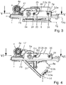
Fig. 1 mit in Betriebsposition ausgeschwenktem Schwenkkörper, - Fig. 3
- eine Seitenansicht der Schwenkbrause auf eine Querseite mit dem Schwenkkörper in Ruheposition,
- Fig. 4
- die Ansicht von
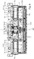
Fig. 3 mit in die Betriebsposition ausgeschwenktem Schwenkkörper, - Fig. 5
- eine Schnittansicht der Schwenkbrause längs einer Linie V-V von
Fig. 3 , - Fig. 6
- eine Schnittansicht der Schwenkbrause längs einer Linie VI-VI von
Fig. 4 , - Fig. 7
- eine teilweise geschnittene Perspektivansicht der Schwenkbrause mit in Betriebsposition ausgeschwenktem Schwenkkörper und
- Fig. 8
- eine Perspektivansicht eines Schwenkachsenbauteils der Schwenkbrause der
Fig. 1 bis 7 . - Die in den
Fig. 1 bis 8 gezeigte Schwenkbrause eignet sich beispielsweise als sanitäre Schwenk-Kopfbrause zur Deckenmontage oder als sanitäre Schwenk-Seitenbrause zur Wandmontage in Duschräumen. Sie beinhaltet einen Grundkörper 1 und einen Schwenkkörper 2, der einen Brauseaustritt 3 aufweist. Der Schwenkkörper 2 ist am Grundkörper 1 zwischen einer ersten Schwenkkörper-Endstellung Rp, die eine brauseinaktive Ruheposition bildet, und einer zweiten Schwenkkörper-Endstellung Bp, die eine brauseaktive Betriebsposition bildet, um eine Schwenkachse Sa schwenkbeweglich gehalten. Ein Brausefluideinlass 4 dient zum Zuführen eines Brausefluids, wie z.B. Duschwasser. Im gezeigten Ausführungsbeispiel ist der Brausefluideinlass 4 durch ein fluideintrittsseitiges Anschlussrohrstück 4a gebildet, das am Grundkörper 1 ausgebildet oder mit diesem verbunden ist. In alternativen Ausführungen ist der Brausefluideinlass 4 in anderer herkömmlicher Weise realisiert und/oder am Schwenkkörper 2 ausgebildet oder mit diesem verbunden. - Ein Schwenkantrieb 5 dient zum angetriebenen Verschwenken des Schwenkkörpers 2, wobei der Schwenkantrieb 5 einen von einem Fluiddruck des zugeführten Brausefluids beaufschlagbaren Schieberkolben 5a aufweist. Der Schieberkolben 5a ist zwischen einer ersten, mit der ersten Schwenkkörper-Endstellung Rp korrespondierenden Kolben-Endstellung K1 und einer zweiten, mit der zweiten Schwenkkörper-Endstellung Bp korrespondierenden Kolben-Endstellung K2 translationsbeweglich angeordnet. Die Translationsbewegung des Schieberkolbens 5a, d.h. dessen lineare Verschiebebewegung, erfolgt in einer Translationsrichtung TR, die eine von Null verschiedene parallele Translationsrichtungskomponente TRp besitzt. Wie für Schieberkolben üblich, ist die Schieberkolben-Translationsrichtung TR parallel zu einer Axialrichtung bzw. Längsachse SL des Schieberkolbens 5a. Im gezeigten Beispiel ist die Schieberkolben-Translationsrichtung TR parallel zur Schwenkachse Sa. In alternativen Ausführungen besitzt die Translationsrichtung TR des Schieberkolbens 5a außer der zur Schwenkachse Sa parallelen Richtungskomponente TRp zusätzlich eine von Null verschiedene, zur Schwenkachse Sa senkrechte Translationsrichtungskomponente, d.h. in diesem Fall ist die Verschieberichtung TR des Schieberkolbens 5a schräg zur Schwenkachse Sa des Schwenkkörpers 2 orientiert.
- Im gezeigten Beispiel bildet eine in den
Fig. 3 und 4 untere Seite der Schwenkbrause eine Frontseite bzw. Sichtseite FS, worunter, wie schon gesagt, diejenige Seite der Schwenkbrause zu verstehen ist, welche dem Benutzer im montierten Zustand der Schwenkbrause, z.B. nach Montage an einem Decken- oder Wandbereich eines Duschraums, zugewandte bzw. für ihn sichtbare Seite zu verstehen ist. Wie weiter z.B. aus denFig. 3 und 4 ersichtlich, ist der Brauseaustritt 3 in der Ruheposition Rp des Schwenkkörpers 2 von der Sichtseite FS der Schwenkbrause weggeschwenkt. Um den Schwenkkörper 2 von seiner Ruheposition Rp als der ersten Schwenkkörper-Endstellung in die brauseaktive Betriebsposition Bp als der zweiten Schwenkkörper-Endstellung zu bewegen, braucht er um höchstens 90° verschwenkt werden. Im gezeigten Ausführungsbeispiel beträgt der Schwenkwinkelhub, d.h. ein Schwenkwinkel αH zwischen den beiden Schwenkkörper-Endstellungen Rp, Bp ca. 45°. In alternativen Ausführungen kann dieser Schwenkwinkelhub αH einen beliebigen anderen Wert vorzugsweise im Bereich zwischen 0° und 90° haben. - Im gezeigten Ausführungsbeispiel ist der Schwenkkörper 2 von einer quaderförmigen Brausekartusche 2a gebildet, die an einer ihrer Quaderseiten den Brauseaustritt 3 und an einer angrenzenden Quaderseite eine Deckfläche 6 aufweist. Die Deckfläche 6 ist in der ersten Schwenkkörper-Endstellung Rp parallel zur Sichtseite FS der Schwenkbrause, d.h. eine Ebene E6 der Deckfläche 6 ist parallel zu einer Ebene EFS der Sichtseite FS. Dadurch tritt für den Benutzer vom Schwenkkörper 2 nur diese Deckfläche 6 optisch in Erscheinung, wenn sich die Schwenkbrause nicht im aktiven Brausebetrieb befindet und daher der Schwenkkörper 2 seine Ruheposition Rp einnimmt. Der Brauseaustritt 3 ist für den Benutzer in diesem Fall unsichtbar in den rahmenförmigen Grundkörper 1 eingeschwenkt. Je nach Wunsch bzw. Bedarf kann die Schwenkbrause mit dieser Deckfläche 6 im Wesentlichen bündig mit einer angrenzenden Fläche der Schwenkbrause und/oder mit einem angrenzenden Decken- oder Wandbereich eines Duschraums abschließen. Zusätzlich oder alternativ kann die Deckfläche eine zu einem angrenzenden Flächenbereich der Schwenkbrause und/oder einer Decke oder Wand eines Duschraums im Wesentlichen einheitliche Oberflächenbeschaffenheit aufweisen, so dass sich der Schwenkkörper 2 in seiner Ruheposition Rp harmonisch und unauffällig in das Gesamtbild der Schwenkbrause an ihrer Sichtseite FS einfügt.
- In alternativen Ausführungen weist der Schwenkkörper 2 eine von einer Quaderform abweichende Form auf, z.B. im Querschnitt eine Dreieckform oder Halbkreisform. Des Weiteren umfasst die Erfindung Ausführungen, bei denen der Schwenkkörper 2 quaderförmig ist, jedoch keine Deckfläche nach Art der Deckfläche 6 aufweist. Zudem kann in entsprechenden alternativen Ausführungsformen der Erfindung die den Brauseaustritt 3 aufweisende Seite des Schwenkkörpers 2 ganz oder teilweise auf der Sichtseite FS der Schwenkbrause liegen, wenn der Schwenkkörper 2 in seiner inaktiven Ruheposition Rp ist.
- Im gezeigten Ausführungsbeispiel weist der Brauseaustritt 3 eine Strahlaustrittsplatte 3a mit wenigstens einer Strahlaustrittsdüse 7 auf, deren Düsenlängsachse Ld einen spitzen Winkel β mit der Strahlaustrittsplatte 3a einschließt. Vorzugsweise beinhaltet die Strahlaustrittsplatte 3a wie gezeigt eine Mehrzahl solcher Strahlaustrittsdüsen 7 mit zueinander parallelen Düsenlängsachsen Ld. Die Strahlaustrittsdüsen 7 können von beliebiger herkömmlicher Art sein, z.B. können sie durch Austrittsnippel, die sich durch zugehörige Öffnungen in der als sogenannte Strahlscheibe fungierenden Strahlaustrittsplatte 3a hindurcherstrecken und vorzugsweise aus einem Elastomermaterial bestehen, oder einfach durch in die Strahlaustrittsplatte 3a eingebrachte Austrittsdüsenöffnungen gebildet sein. Im aktiven Brausebetrieb erzeugen die Strahlaustrittsdüsen 7 einen Brausestrahl mit zu den Düsenlängsachsen Ld paralleler Hauptstrahlrichtung, d.h. das Brausefluid verlässt die Brause mit dieser zu den Düsenlängsachsen Ld parallelen Vorzugsrichtung, die auch als eine Längsachse des Brausestrahls verstanden werden kann.
- Durch die Schrägneigung der Düsenlängsachsen Ld gegenüber der Strahlaustrittsplatte 3a um den Winkel β kann im gezeigten Ausführungsbeispiel vom Brauseaustritt 3 ein Brausestrahl abgegeben werden, dessen Hauptstrahlrichtung senkrecht oder annähernd senkrecht zur Sichtseite FS der Brause verläuft, obwohl die Strahlaustrittsplatte 3a in der eingeschwenkten Ruheposition Rp senkrecht zur Sichtseite FS der Brause orientiert ist und die Brausekartusche 2a nur um z.B. 45° bis 50° in die aktive Betriebsposition Bp ausgeschwenkt wird. Die Winkellage der Hauptstrahlrichtung des Brausestrahls relativ zur Sichtseite FS der Brause ergibt sich aus der Addition des Schwenkwinkelhubs αH und des Schrägwinkels 90°-β der Düsenlängsachsen Ld bezüglich einer Ebenennormalen der Strahlaustrittsplatte 3a und kann somit durch geeignete Wahl der Winkel αH und β auf einen beliebigen gewünschten Wert eingestellt werden, z.B. im Bereich von 70° bis 90°.
- Zur Fluiddruckbeaufschlagung des Schieberkolbens 5a weist die Schwenkbrause einen mit dem Brausefluideinlass 4 in Fluidverbindung stehenden Kolbenraum 8 auf, der über einen Verbindungskanal 9 mit dem fluideintrittsseitigen Anschlussrohrstück 4a in Verbindung steht. Der Schieberkolben 5a ist im gezeigten Beispiel als hohlzylindrisches Bauteil mit zum Kolbenraum 8 hin geschlossener Stirnseite und gegenüberliegend offener Stirnseite ausgeführt.
- Mit seiner offenen Stirnseite ist der Schieberkolben 5a auf eine Schwenkwellenhülse 10 aufschiebbar, wobei er diese koaxial umgibt. Die Schwenkwellenhülse 10 ist am Grundkörper 1 ausgebildet oder an diesem angebracht und definiert mit ihrer Längsmittenachse die Schwenkachse Sa des gegenüber dem Grundkörper 1 verschwenkten Schwenkkörpers 2. Dazu ist der Schwenkkörper 2 schwenkbeweglich an der Schwenkwellenhülse 10 gehalten bzw. gelagert. Gleichzeitig dient die Schwenkwellenhülse 10 in diesem Ausführungsbeispiel als Führung für den translationsbeweglichen Schieberkolben 5a und/oder als teleskopartig mit dem Schieberkolben 5a zusammenwirkendes Bauteil. Im gezeigten Ausführungsbeispiel ist die Schwenkwellenhülse 10 an einem Schwenkachsenbauteil 22 ausgebildet, das zudem einen am einen Ende der Schwenkwellenhülse 10 radial abstehenden Befestigungsflansch 23 aufweist, an dem im Abstand voneinander zwei Haltebolzenstummel 24 seitlich abstehend angeordnet sind, wie insbesondere aus
Fig. 8 ersichtlich. Mit den Haltebolzenstummeln 24 kann das Schwenkachsenbauteil 22 in korrespondierende Ausnehmungen 25 eines Querträgers 26 des Grundkörpers 1 eingehängt und dadurch am Rahmen des Grundkörpers 1 gehalten werden. - Im gezeigten Ausführungsbeispiel beinhaltet der Schwenkantrieb 5 zudem ein Übertragungselement zur Übertragung der Translationsbewegung des Schieberkolbens 5a in die Schwenkbewegung des Schwenkkörpers 2, wobei das Übertragungselement in Form einer Kulissenführung 5b realisiert ist. In einer vorteilhaften, gezeigten Ausführung umfasst die Kulissenführung 5b ein erstes Führungsteil 11, das eine Kulissenbahn 11a beinhaltet, und ein zweites Führungsteil 12, das einen mit der Kulissenbahn 11a zusammenwirkenden Kulissennocken 12a aufweist. Von den beiden Führungsteilen 11, 12 ist das eine Führungsteil unbewegt am Grundkörper 1 angeordnet, während das andere Führungsteil mit der Translationsbewegung des Schieberkolbens 5a translationsbeweglich und mit dem Schwenkkörper 2 drehgekoppelt angeordnet ist. Beispielsweise kann, wie gezeigt, das erste Führungsteil 11 mit der Kulissenbahn 11a stationär am Grundkörper 1 angeordnet sein, während das zweite Führungsteil 12 mit dem Kulissennocken 12a mit der Translationsbewegung des Schieberkolbens 5a translationsbeweglich und mit dem Schwenkkörper 2 drehgekoppelt ist.
- In einer exemplarischen Realisierung beinhaltet das zweite Führungsteil 12 eine mit einer Stirnseite des Schieberkolbens 5a zusammenwirkende Mitnehmerhülse 12'. Das die Kulissenbahn 11a enthaltende Führungsteil 11 ist im gezeigten Beispiel vorteilhaft durch die Schwenkwellenhülse 10 gebildet, in alternativen Ausführungen der Erfindung bildet das Führungsteil 11 ein von der Schwenkwellenhülse 10 verschiedenes, vorzugsweise hülsenförmiges Bauteil, das am Grundkörper 1 ausgebildet bzw. unbewegt an diesem angebracht ist. Die Kulissenbahn 11a ist im gezeigten Beispiel, wie insbesondere aus
Fig. 8 ersichtlich, als gewundene Bahn mit einer kombinierten Axialrichtungs- und Umfangsrichtungskomponente in das hülsenförmige Führungsteil 11 eingebracht. Der Kulissennocken 12a ragt von der Mitnehmerhülse 12'radial nach innen und greift in die Kulissenbahn 11a ein. Dies ist ausFig. 7 ersichtlich, bei der zu diesem Zweck ein Teil der umgebenden Bauteile fensterartig ausgeschnitten gezeigt ist. - Die Mitnehmerhülse 12' schließt axial an das offene Stirnende des Schieberkolbens 5a an und besitzt einen etwa gleich großen Durchmesser. Dadurch wird die Mitnehmerhülse 12', wenn der Schieberkolben 5a aufgrund des Fluiddrucks des zugeführten Brausefluids von seiner ersten Kolben-Endstellung K1 in Richtung seiner zweiten Kolben-Endstellung K2 verschoben wird, vom Schieberkolben 5a axial mitbewegt. Durch das Zusammenwirken des Kulissennockens 12a mit der stationär bleibenden Kulissenbahn 11a hat die Axialbewegung der Mitnehmerhülse 12' ein gleichzeitiges Verdrehen der Mitnehmerhülse 12' zur Folge. Dies wiederum bewirkt wegen der Drehkopplung des Schwenkkörpers 2 mit der Mitnehmerhülse 12' das gewünschte Verschwenken des Schwenkkörpers 2.
- Im gezeigten Ausführungsbeispiel ist die Drehkopplung des Schwenkkörpers 2 mit der Mitnehmerhülse 12' als drehfeste Verbindung realisiert, wozu die Mitnehmerhülse 12' einen oder mehrere axial verlaufende Mitnehmerstege 12b aufweist, die von ihrer Außenseite radial abstehen und jeweils in eine zugeordnete Axialnut 13a eingreifen, die an der Innenseite einer Schwenkkörperhülse 13 ausgebildet ist/sind, welche einteilig am Schwenkkörper 2 ausgebildet oder als separates Bauteil drehstarr mit dem Schwenkkörper 2 verbunden ist. Ein Verdrehen der Mitnehmerhülse 12' hat somit ein entsprechendes Verdrehen der Schwenkkörperhülse 13 und damit des gesamten Schwenkkörpers 2 zur Folge. In alternativen Ausführungen der Erfindung kann der Schwenkkörper über ein herkömmliches Getriebe, je nach Bedarf mit gewünschter Über- oder Untersetzung, mit der Mitnehmerhülse drehgekoppelt sein.
- Die Schwenkkörperhülse 13 dient zusammen mit der hierfür als Nabe fungierenden Schwenkwellenhülse 10 als Schwenklagerung für den Schwenkkörper 2 am Grundkörper 1. Dazu ist die Schwenkkörperhülse 13 drehbeweglich auf die Schwenkwellenhülse 10 aufgesetzt. In einem zwischen der Schwenkwellenhülse 10 und der Schwenkkörperhülse 13 verbleibenden Ringraum 14 ist die Mitnehmerhülse 12' aufgenommen. Zudem kann sich der hülsenförmige Schieberkolben 5a bei Fluiddruckbeaufschlagung mit seiner offenen Seite in diesen Ringraum 14 hineinbewegen, wobei er die Mitnehmerhülse 12' vor sich herschiebt.
- In einer vorteilhaften Ausführung beinhaltet die Schwenkbrause ein elastisches Kolbenrückstellelement 15, das den Schieberkolben 5a in seine erste Endstellung K1 vorspannt und das im gezeigten Beispiel durch eine Schraubendruckfeder 15a gebildet ist. In alternativen Ausführungen kann das elastische Kolbenrückstellelement 15 als Zugfeder oder als ein gummielastisches Element gebildet sein. Im gezeigten Ausführungsbeispiel ist die Schraubendruckfeder 15a im Ringspalt 14 aufgenommen, wobei sie sich einerseits an einer Ringschulter der Schwenkwellenhülse 10 und andererseits an der Mitnehmerhülse 12' abstützt. Auf diese Weise drückt die Schraubendruckfeder 15a das Mitnehmerelement 12' und mit ihm den Schieberkolben 5a in Richtung der ersten Kolben-Endstellung K1, die der Ruheposition Rp des Schwenkkörpers 2 entspricht.
- Außerhalb des Ringspalts 14 ist der Schieberkolben 5a axial anschließend an die Schwenklagerung des Schwenkkörpers 2 mit der Schwenkwellenhülse 10 und der Schwenkkörperhülse 13 in einem Kolbenaufnahmezylinder 16 fluiddicht geführt. Der Kolbenaufnahmezylinder 16 ist Teil des gegenüber dem Schwenkkörper 2 stationären Grundkörpers 1 und definiert bzw. umgrenzt den Kolbenraum 8.
- Im gezeigten Ausführungsbeispiel sind der Schwenkkörper 2 und der Grundkörper 1 wie gezeigt im Wesentlichen symmetrisch zu einer Mittenebene ME der Schwenkbrause ausgebildet. Dies bedeutet, dass die gezeigte Schwenkbrause u.a. zwei Schwenklagerungen mit jeweiliger Schwenkwellenhülse 10 und Schwenkkörperhülse 13 und zwei Schwenkantriebe 5 mit jeweiligem Schieberkolben 5a und Kulissenführung 5b der erläuterten Art in entsprechend spiegelsymmetrischer bzw. zur Mittenebene ME symmetrischer Anordnung umfasst.
- Zwischen den beiden Schieberkolben 5a bzw. den Kolbenaufnahmezylindern 16 befindet sich ein Fluidführungsbauteil 17, das zu einem Teil zum unbewegten Grundkörper 1 gehört und zu einem demgegenüber drehbeweglichen, anderen Teil zum verschwenkbaren Schwenkkörper 2 gehört. Das Fluidführungsbauteil 17 besitzt ebenfalls einen zur Mittenebene ME im Wesentlichen symmetrischen Aufbau und beinhaltet auf jeder Seite in einem Abschnitt eines Fluidströmungsweges, der zwischen dem Brausefluideinlass 4 bzw. dem Anschlussrohrstück 4a und dem Brauseaustritt 3 bzw. einer in der Brausekartusche 2a stromaufwärts des Brauseaustritts 3 vorgesehenen, üblichen Fluidaustrittskammer gebildet ist, je ein Absperrventil 18. Die beiden synchron arbeitenden Absperrventile 18 sperren den Fluidströmungsweg abhängig von einer Schwenklage des Schwenkkörpers 2 ab bzw. geben ihn frei, wobei sie den Fluidströmungsweg in der Ruheposition Rp des Schwenkkörpers 2 vollständig absperren und ihn in der Betriebsposition Bp des Schwenkkörpers 2 vollständig freigeben.
- Im gezeigten Beispiel befinden sich die beiden Absperrventile 18 in je einem Verbindungskanal 19 vom Anschlussrohrstück 4a zu einem Anschlussstutzen 20, mit dem der betreffende Teil des Fluidführungsbauteils 17 starr mit dem Schwenkkörper 2 verbunden ist, und beinhalten je eine Ventilkugel 18a als Ventilschließkörper und eine Ventilsteuerkontur 18b an einem Außenumfang einer entsprechenden Ventilsteuerhülse. Die jeweilige Ventilsteuerhülse und folglich deren Ventilsteuerkontur 18b verschwenken sich mit dem Schwenkkörper 2 mit.
- Die Ventilsteuerkontur 18b ist dergestalt geformt, dass sie der Ventilkugel 18a mit einer Absperrkontur gegenüberliegt, wenn sich der Schwenkkörper 2 in der Ruheposition Rp befindet, während sie der Ventilkugel 18a mit einer Freigabekontur gegenüberliegt, wenn sich der Schwenkkörper 2 in der Betriebsposition Bp befindet. Die Absperrkontur ist in einer herkömmlichen Weise derart gebildet, dass der betreffende Fluidströmungskanal vollständig abgesperrt wird, wenn die Ventilkugel 18a mit der Absperrkontur zusammenwirkt. Die Freigabekontur ist so gebildet, dass der betreffende Fluidkanal freigegeben, d.h. nicht vollständig abgesperrt, wird, d.h. Fluid an der Ventilkugel 18a und der Ventilsteuerkontur 18b vorbeiströmen kann, wenn die Ventilkugel 18a mit der Freigabekontur zusammenwirkt. Derartige Absperr- und Freigabekonturen sind dem Fachmann an sich bekannt und bedürfen daher hier keiner näheren Erläuterung. Je nach dem, über welchen Umfangswinkel sich die Absperrkontur bzw. die Freigabekontur erstrecken, sperrt das Absperrventil 18 den Fluidströmungsweg über einen entsprechenden Schwenkwinkel des Schwenkkörpers 2 hinweg ab bzw. gibt ihn frei.
- In einer vorteilhaften optionalen Ausführungsvariante weist das jeweilige Absperrventil 18 eine Schalthysterese auf, durch die es den Fluidströmungsweg beim Verschwenken des Schwenkkörpers 2 aus seiner Ruheposition Rp in Richtung der Betriebsposition Bp später freizugeben beginnt als es ihn beim Verschwenken des Schwenkkörpers 2 aus der Betriebsstellung Bp in Richtung der Ruheposition Rp vollständig absperrt. Dadurch kann beim Zurückschwenken des Schwenkkörpers 2 in seine Ruheposition Rp noch etwas länger Brausefluid aus dem Brauseaustritt 3 austreten, bevor dann das Absperrventil 18 die Brausefluidzufuhr zum Brauseaustritt 3 vollständig absperrt, sobald der Schwenkkörper 2 eine bestimmte Absperrwinkellage in oder vor seiner Ruheposition Rp erreicht hat. Hingegen tritt beim Herausschwenken des Schwenkkörpers 2 aus seiner Ruheposition Rp Brausefluid erst dann aus dem Brauseaustritt 3 aus, wenn der Schwenkkörper 2 eine Freigabewinkellage erreicht hat, die von der Ruheposition Rp um einen der Schalthysterese entsprechenden Differenzwinkel weiter entfernt ist als die Absperrwinkellage. Dadurch kann beim Zurückschwenken des Schwenkkörpers 2 in seine Ruheposition Rp noch entsprechend länger Brausefluid, das aus dem jeweiligen Kolbenraum 8 über den Verbindungskanal 9 zurückgedrückt wird, aus der Schwenkbrause austreten, was entsprechende Fluiddruckbelastungen in der Brause vermeidet.
- Für das jeweilige Absperrventil ist insbesondere auch ein solches verwendbar, wie es in einer parallelen deutschen Patentanmeldung der Anmelderin (unser Zeichen P
56392 DE ) offenbart ist, deren Inhalt hierfür in vollem Umfang durch Verweis in die vorliegende Anmeldung aufgenommen wird. - In einer vorteilhaften, optionalen Ausführungsvariante beinhaltet die Schwenkbrause ein Arretierelement 21, mit dem der Schwenkkörper 2 in seiner Betriebsposition Bp arretiert und auf diese Weise unabhängig vom herrschenden Fluiddruck festgehalten werden kann. Das Arretierelement 21 kann beispielsweise ein herkömmlicher Arretierstift sein, der von einer inaktiven Position in eine Arretierstellung bewegt werden kann, wenn sich der Schwenkkörper 2 in der Betriebsposition Bp befindet. In der Arretierstellung stützt sich der Arretierstift einerseits am Grundkörper 1 und andererseits am Schwenkkörper 2 ab und sichert dadurch den Schwenkkörper 2 in dieser Betriebsposition Bp. Durch Lösen des Arretierelements 21 kann das Zurückschwenken des Schwenkkörpers 2 aus seiner Betriebsposition Bp wieder freigegeben werden. Ein solches Arretieren des Schwenkkörpers 2 ist beispielsweise für Wartungs- und Reparaturarbeiten nützlich. So können z.B. bei Bedarf die Strahlaustrittsdüsen 7 bei abgestellter Brause in dieser Betriebsposition Bp des Schwenkkörpers 2 gereinigt werden, in welcher die Strahlaustrittsdüsen 7 gut zugänglich sind.
- Aus den obigen Erläuterungen zum Aufbau der Schwenkbrause wird auch deren vorteilhafte Funktionsweise deutlich. Im inaktiven Betriebszustand wird der Schwenkbrause kein Fluid zugeführt. Die Schwenkbrause befindet sich im quasi fluiddrucklosen Zustand, in welchem der jeweilige Schieberkolben 5a seine erste Endposition K1 einnimmt und in dieser Position mittels des elastischen Kolbenrückstellelements 15 vorgespannt gehalten wird. Entsprechend befindet sich der Schwenkkörper 2 in seiner Ruheposition Rp. Wenn der Benutzer durch Aktivieren der Fluidzufuhr die Brause aktiviert, z.B. durch Öffnen eines vorliegend nicht gezeigten, der Schwenkbrause vorgeschalteten, üblichen Fluidzufuhr-Absperrventils, gelangt Fluid über den Einlass 4 in das Anschlussrohrstück 4a und von dort zum einen zum jeweiligen Absperrventil 18 und zum anderen in den jeweiligen Kolbenraum 8. Das Absperrventil 18 befindet sich noch in seiner Absperrposition, so dass noch kein Fluid aus der Brause austritt.
- Durch den sich im Kolbenraum 8 aufbauenden Fluiddruck wird der jeweilige Schieberkolben 5a entgegen der Vorspannkraft des elastischen Kolbenrückstellelements 15 vorgeschoben, wodurch er die Mitnehmerhülse 12' vorschiebt. Dabei wird die Mitnehmerhülse 12' aufgrund der Kulissenführung 5b gleichzeitig verdreht, was wiederum den Schwenkkörper 2 entsprechend aus seiner Ruheposition Rp heraus verdreht bzw. verschwenkt. Sobald der Schwenkkörper 2 seine Freigabewinkellage erreicht hat, öffnet das jeweilige Absperrventil 18 den weiteren Fluidströmungsweg in den Schwenkkörper 2 bzw. zu dessen Brauseaustritt 3, woraufhin das Brausefluid wie gewünscht aus dem Brauseaustritt 3 als Brausestrahl austritt. Falls die Freigabewinkellage des Schwenkkörpers 2 noch nicht seiner voll ausgeschwenkten Betriebsposition Bp entspricht, verschwenkt sich der Schwenkkörper 2 vollends in die Betriebsposition Bp, da der Fluiddruck im Kolbenraum 8 den jeweiligen Schieberkolben 5a bis zu dessen Erreichen seiner entsprechenden Endposition K2 vorschiebt.
- Zum Beenden des Brausebetriebs stellt der Benutzer die Fluidzufuhr zur Schwenkbrause ab. Dadurch fällt der Fluiddruck im jeweiligen Kolbenraum 8 ab, und das elastische Rückstellelement 15 drückt die Mitnehmerhülse 12' und mit ihr den jeweiligen Schieberkolben 5a axial zurück. Hierbei dreht sich die Mitnehmerhülse 12' gleichzeitig wieder aufgrund der Kulissenführung 5b zurück, wodurch sich entsprechend der Schwenkkörper 2 zurück verschwenkt. Das jeweilige Absperrventil 18 bleibt ganz oder zumindest teilweise geöffnet, bis der zurückschwenkende Schwenkkörper 2 seine Absperrwinkellage erreicht hat. Bis dahin kann Fluid, das durch die Rückbewegung der Schieberkolben 5a aus den beiden Kolbenräumen 8 in das Anschlussrohrstück 4a zurückgedrückt wird, über die beiden Absperrventile 18 zum Brauseaustritt 3 gelangen und aus der Brause austreten. Nach erreichter Absperrwinkellage sperren die Absperrventile 18 den Fluidströmungsweg zum Brauseaustritt 3 ab, so dass kein Brausefluid mehr aus ihm austritt. Falls der Schwenkkörper 2 sich dabei noch nicht in seiner Ruheposition Rp befindet, schwenkt er anschließend vollends in die Ruheposition Rp zurück, indem die Schieberkolben 5a von den elastischen Rückstellelementen 15 in ihre zugehörige Endposition K1 zurückgedrückt werden und sich hierbei die Mitnehmerhülsen 12' entsprechend axial zurückbewegen und sich dabei mittels der Kulissenführungen 5b verdrehen.
- Wie das oben erläuterte, gezeigte und die oben erläuterten weiteren Ausführungsbeispiele deutlich machen, stellt die Erfindung eine Schwenkbrause mit sehr vorteilhaften Eigenschaften und relativ einfachem Aufbau zur Verfügung. Die Schwenkbrause ist insbesondere im Sanitärbereich und hier speziell als wand- oder deckenmontierte Seiten- bzw. Kopfbrause verwendbar. Es versteht sich jedoch, dass die Schwenkbrause in gleicher Weise für nicht-sanitäre Anwendungen überall dort nutzbringend einsetzbar ist, wo Bedarf an einer Brause mit einem verschwenkbaren Brauseaustritt besteht.
Claims (10)
- Schwenkbrause, insbesondere wand- oder deckenmontierte sanitäre Schwenkbrause, mit- einem Grundkörper (1),- einem Schwenkkörper (2), der einen Brauseaustritt (3) aufweist und am Grundkörper zwischen einer ersten Schwenkkörper-Endstellung (Rp), die eine Ruheposition bildet, und einer zweiten Schwenkkörper-Endstellung (Bp), die eine Betriebsposition bildet, um eine Schwenkachse (Sa) schwenkbeweglich gehalten ist,- einem Brausefluideinlass (4) zum Zuführen eines Brausefluids und- einem Schwenkantrieb (5) zum angetriebenen Verschwenken des Schwenkkörpers, wobei der Schwenkantrieb einen von einem Fluiddruck des zugeführten Brausefluids beaufschlagbaren Schieberkolben (5a) aufweist, der zwischen einer ersten, mit der ersten Schwenkkörper-Endstellung korrespondierenden Kolben-Endstellung (K1) und einer zweiten, mit der zweiten Schwenkkörper-Endstellung korrespondierenden Kolben-Endstellung (K2) translationsbeweglich angeordnet ist,dadurch gekennzeichnet, dass- der Schieberkolben (5a) mit zur Schwenkachse (Sa) paralleler Translationsrichtungskomponente (TRp) angeordnet ist und/oder- der Schwenkantrieb (5) ein Übertragungselement in Form einer Kulissenführung (5b) zwischen dem Schieberkolben (5a) und dem Schwenkkörper (2) beinhaltet, wobei das Übertragungselement die Translationsbewegung des Schieberkolbens in eine Schwenkbewegung des Schwenkkörpers überträgt, und/oder- der Brauseaustritt in der Ruheposition (Rp) des Schwenkkörpers (2) von einer Sichtseite (FS) der Schwenkbrause weggeschwenkt ist und ein Schwenkwinkelhub (αH) von der ersten (Rp) in die zweite Schwenkkörper-Endstellung (Bp) höchstens 90° beträgt.
- Schwenkbrause nach Anspruch 1, weiter dadurch gekennzeichnet, dass die Kulissenführung ein erstes Führungsteil (11), das eine Kulissenbahn (11a) beinhaltet, und ein zweites Führungsteil (12) umfasst, das einen mit der Kulissenbahn zusammenwirkenden Kulissennocken (12a) aufweist, wobei von den beiden Führungsteilen das eine Führungsteil unbewegt am Grundkörper angeordnet ist und das andere Führungsteil mit der Translationsbewegung des Schieberkolbens translationsbeweglich und mit dem Schwenkkörper drehgekoppelt angeordnet ist.
- Schwenkbrause nach Anspruch 2, weiter dadurch gekennzeichnet, dass das andere Führungsteil eine mit einer Stirnseite des Schieberkolbens zusammenwirkende Mitnehmerhülse (12') beinhaltet.
- Schwenkbrause nach einem der Ansprüche 1 bis 3, weiter dadurch gekennzeichnet, dass der Schieberkolben an einer die Schwenkachse definierenden Schwenkwellenhülse (10) translationsbeweglich geführt ist und/oder teleskopartig auf die Schwenkwellenhülse aufschiebbar oder in diese einschiebbar ist.
- Schwenkbrause nach einem der Ansprüche 1 bis 4, weiter gekennzeichnet durch ein elastisches Kolbenrückstellelement (15), das den Schieberkolben in die erste Kolben-Endstellung vorspannt.
- Schwenkbrause nach einem der Ansprüche 1 bis 5, weiter dadurch gekennzeichnet, dass der Schwenkkörper von einer quaderförmigen Brausekartusche (2a) gebildet ist, die an einer ihrer Quaderseiten den Brauseaustritt und an einer angrenzenden Quaderseite eine Deckfläche (6) aufweist, die in der ersten Schwenkkörper-Endstellung parallel zur Sichtseite der Schwenkbrause ist.
- Schwenkbrause nach einem der Ansprüche 1 bis 6, weiter gekennzeichnet durch ein Arretierelement (21), mit dem der Schwenkkörper in der zweiten Schwenkkörper-Endstellung arretierbar ist.
- Schwenkbrause nach einem der Ansprüche 1 bis 7, weiter dadurch gekennzeichnet, dass der Brauseaustritt eine Strahlaustrittsplatte (3a) mit wenigstens einer Strahlaustrittsdüse (7) aufweist, deren Düsenlängsachse (Ld) einen spitzen Winkel (β) mit der Strahlaustrittsplatte einschließt.
- Schwenkbrause nach einem der Ansprüche 1 bis 8, weiter gekennzeichnet durch ein in einem Fluidströmungsweg zwischen dem Brausefluideinlass und dem Brauseaustritt angeordnetes Absperrventil (18), das den Fluidströmungsweg abhängig von einer Schwenklage des Schwenkkörpers absperrt und freigibt, wobei es den Fluidströmungsweg in der ersten Schwenkkörper-Endstellung vollständig absperrt und ihn in der zweiten Schwenkkörper-Endstellung vollständig freigibt.
- Schwenkbrause nach Anspruch 9, weiter dadurch gekennzeichnet, dass das Absperrventil eine Schalthysterese aufweist, durch die es den Fluidströmungsweg beim Verschwenken des Schwenkkörpers aus der ersten Schwenkkörper-Endstellung in Richtung der zweiten Schwenkkörper-Endstellung später freizugeben beginnt als es ihn beim Verschwenken des Schwenkkörpers aus der zweiten Schwenkkörper-Endstellung in Richtung der ersten Schwenkkörper-Endstellung vollständig absperrt.
Applications Claiming Priority (1)
| Application Number | Priority Date | Filing Date | Title |
|---|---|---|---|
| DE102017203945.0A DE102017203945B3 (de) | 2017-03-09 | 2017-03-09 | Schwenkbrause mit fluiddruckgetriebenem Schwenkkörper |
Publications (3)
| Publication Number | Publication Date |
|---|---|
| EP3372317A1 true EP3372317A1 (de) | 2018-09-12 |
| EP3372317B1 EP3372317B1 (de) | 2021-02-24 |
| EP3372317B8 EP3372317B8 (de) | 2021-04-07 |
Family
ID=61557213
Family Applications (1)
| Application Number | Title | Priority Date | Filing Date |
|---|---|---|---|
| EP18159761.8A Active EP3372317B8 (de) | 2017-03-09 | 2018-03-02 | Schwenkbrause mit fluiddruckgetriebenem schwenkkörper |
Country Status (6)
| Country | Link |
|---|---|
| US (1) | US10751746B2 (de) |
| EP (1) | EP3372317B8 (de) |
| CN (1) | CN108568355B (de) |
| DE (1) | DE102017203945B3 (de) |
| RU (1) | RU2683095C1 (de) |
| ZA (1) | ZA201801567B (de) |
Families Citing this family (5)
| Publication number | Priority date | Publication date | Assignee | Title |
|---|---|---|---|---|
| DE102018208124A1 (de) * | 2018-05-23 | 2019-11-28 | Hansgrohe Se | Fluidauslaufvorrichtung mit Teleskoprohrauslauf |
| US11338315B2 (en) * | 2019-12-31 | 2022-05-24 | A. Raymond Et Cie | Articulating nozzle |
| US11426741B2 (en) * | 2020-10-23 | 2022-08-30 | Purity (Xiamen) Sanitary Ware Co., Ltd. | Water output device |
| CN112762215B (zh) * | 2021-01-20 | 2025-05-27 | 火星人厨具股份有限公司 | 一种四级电动下水控制结构及其运作方法 |
| US20240316575A1 (en) * | 2024-06-04 | 2024-09-26 | Xiamen Galenpoo Kitchen&Bathroom Technology Co., Ltd | Auto-swinging shower |
Citations (6)
| Publication number | Priority date | Publication date | Assignee | Title |
|---|---|---|---|---|
| DE4130892A1 (de) * | 1990-09-17 | 1992-03-19 | Peugeot | Teleskopische scheinwerferwaschvorrichtung fuer kraftfahrzeuge |
| US5159722A (en) * | 1990-04-03 | 1992-11-03 | Geberit Ag. | Drive for a shower arm or a bidet device |
| DE19945854A1 (de) * | 1999-09-24 | 2001-03-29 | Bosch Gmbh Robert | Scheinwerferwaschvorrichtung |
| US6343389B1 (en) * | 1997-10-18 | 2002-02-05 | David Timothy Lloyd Jones | Water outlets for an ablutionary device or appliance |
| EP1947252A2 (de) * | 2007-01-16 | 2008-07-23 | Hansgrohe AG | Duscheinrichtung |
| EP1947251B1 (de) | 2007-01-16 | 2014-04-30 | Hansgrohe SE | Duschvorrichtung |
Family Cites Families (4)
| Publication number | Priority date | Publication date | Assignee | Title |
|---|---|---|---|---|
| US7455247B2 (en) * | 2005-03-01 | 2008-11-25 | Kohler Co. | Bodyspray having adjustable spray orientation |
| DE102005011294A1 (de) | 2005-03-04 | 2006-09-07 | Hansgrohe Ag | Brauseeinrichtung |
| DE102008031558A1 (de) * | 2008-07-07 | 2010-01-14 | Grohe Ag | Kopf- oder Seitenbrause |
| RU79902U1 (ru) * | 2008-10-13 | 2009-01-20 | Общество с ограниченной ответственностью "ГИДРОМАШ" | Автоматическая душевая установка |
-
2017
- 2017-03-09 DE DE102017203945.0A patent/DE102017203945B3/de active Active
-
2018
- 2018-03-02 EP EP18159761.8A patent/EP3372317B8/de active Active
- 2018-03-05 RU RU2018107966A patent/RU2683095C1/ru active
- 2018-03-07 ZA ZA2018/01567A patent/ZA201801567B/en unknown
- 2018-03-08 US US15/916,233 patent/US10751746B2/en active Active
- 2018-03-09 CN CN201810194521.3A patent/CN108568355B/zh active Active
Patent Citations (6)
| Publication number | Priority date | Publication date | Assignee | Title |
|---|---|---|---|---|
| US5159722A (en) * | 1990-04-03 | 1992-11-03 | Geberit Ag. | Drive for a shower arm or a bidet device |
| DE4130892A1 (de) * | 1990-09-17 | 1992-03-19 | Peugeot | Teleskopische scheinwerferwaschvorrichtung fuer kraftfahrzeuge |
| US6343389B1 (en) * | 1997-10-18 | 2002-02-05 | David Timothy Lloyd Jones | Water outlets for an ablutionary device or appliance |
| DE19945854A1 (de) * | 1999-09-24 | 2001-03-29 | Bosch Gmbh Robert | Scheinwerferwaschvorrichtung |
| EP1947252A2 (de) * | 2007-01-16 | 2008-07-23 | Hansgrohe AG | Duscheinrichtung |
| EP1947251B1 (de) | 2007-01-16 | 2014-04-30 | Hansgrohe SE | Duschvorrichtung |
Also Published As
| Publication number | Publication date |
|---|---|
| EP3372317B1 (de) | 2021-02-24 |
| DE102017203945B3 (de) | 2018-03-29 |
| ZA201801567B (en) | 2018-11-28 |
| CN108568355A (zh) | 2018-09-25 |
| US20180257097A1 (en) | 2018-09-13 |
| US10751746B2 (en) | 2020-08-25 |
| CN108568355B (zh) | 2020-12-18 |
| EP3372317B8 (de) | 2021-04-07 |
| RU2683095C1 (ru) | 2019-03-26 |
Similar Documents
| Publication | Publication Date | Title |
|---|---|---|
| EP3372317B1 (de) | Schwenkbrause mit fluiddruckgetriebenem schwenkkörper | |
| EP2287409B1 (de) | Sanitärer Wasserauslauf mit verschwenkbarer Strömungsführung | |
| EP1947251B1 (de) | Duschvorrichtung | |
| EP0732148B1 (de) | Mehrfunktions-Handbrause | |
| DE4230535C2 (de) | Zweikomponenten-Spritzpistole | |
| EP1947252B1 (de) | Duscheinrichtung | |
| EP3317003B1 (de) | Beschichtungsmittelventil | |
| DE2102252B2 (de) | Luftfreie Spritzpistole | |
| WO2006029680A1 (de) | Reinigungslanze | |
| EP0886036B1 (de) | Druckluft-Kolbenmotor | |
| EP1259331B1 (de) | Brausekopf | |
| CH687561A5 (de) | Sanitaeres Einhebel-Mischventil. | |
| DE3690557C2 (de) | ||
| EP3517211A1 (de) | Brausekopf mit überdruckventil | |
| EP3372315B1 (de) | Schwenkbrause mit absperrventil | |
| EP0846904A1 (de) | Ventilanordnung mit direkt betätigtem Ventilkörper | |
| DE4341196A1 (de) | Brausekopf | |
| DE2200671A1 (de) | Selbstschliessendes Absperrorgan | |
| EP0927580B1 (de) | Handbrause | |
| DE9315493U1 (de) | Hochdruck-Mischkopf mit einstellbarem Durchflußbegrenzer | |
| EP2280783B1 (de) | Handbrause mit einem an einem handgriff angeordneten brausekopf | |
| WO2009115194A1 (de) | Brausekopf | |
| DE102005059999B4 (de) | Wasserausflussarmatur | |
| WO2019219960A2 (de) | Zylinderanordnung | |
| DE2545636A1 (de) | Luftdruckbetriebene zylinder-kolben- einheit, insbesondere zur betaetigung von schiebetueren u.dgl. |
Legal Events
| Date | Code | Title | Description |
|---|---|---|---|
| PUAI | Public reference made under article 153(3) epc to a published international application that has entered the european phase |
Free format text: ORIGINAL CODE: 0009012 |
|
| STAA | Information on the status of an ep patent application or granted ep patent |
Free format text: STATUS: THE APPLICATION HAS BEEN PUBLISHED |
|
| AK | Designated contracting states |
Kind code of ref document: A1 Designated state(s): AL AT BE BG CH CY CZ DE DK EE ES FI FR GB GR HR HU IE IS IT LI LT LU LV MC MK MT NL NO PL PT RO RS SE SI SK SM TR |
|
| AX | Request for extension of the european patent |
Extension state: BA ME |
|
| STAA | Information on the status of an ep patent application or granted ep patent |
Free format text: STATUS: REQUEST FOR EXAMINATION WAS MADE |
|
| 17P | Request for examination filed |
Effective date: 20190125 |
|
| RBV | Designated contracting states (corrected) |
Designated state(s): AL AT BE BG CH CY CZ DE DK EE ES FI FR GB GR HR HU IE IS IT LI LT LU LV MC MK MT NL NO PL PT RO RS SE SI SK SM TR |
|
| RIC1 | Information provided on ipc code assigned before grant |
Ipc: B05B 15/74 20180101ALI20200804BHEP Ipc: B05B 1/18 20060101ALI20200804BHEP Ipc: B05B 15/652 20180101AFI20200804BHEP Ipc: B05B 1/30 20060101ALN20200804BHEP |
|
| GRAP | Despatch of communication of intention to grant a patent |
Free format text: ORIGINAL CODE: EPIDOSNIGR1 |
|
| STAA | Information on the status of an ep patent application or granted ep patent |
Free format text: STATUS: GRANT OF PATENT IS INTENDED |
|
| INTG | Intention to grant announced |
Effective date: 20200916 |
|
| GRAS | Grant fee paid |
Free format text: ORIGINAL CODE: EPIDOSNIGR3 |
|
| GRAA | (expected) grant |
Free format text: ORIGINAL CODE: 0009210 |
|
| STAA | Information on the status of an ep patent application or granted ep patent |
Free format text: STATUS: THE PATENT HAS BEEN GRANTED |
|
| REG | Reference to a national code |
Ref country code: DE Ref legal event code: R108 Ref document number: 502018003949 Country of ref document: DE |
|
| AK | Designated contracting states |
Kind code of ref document: B1 Designated state(s): AL AT BE BG CH CY CZ DE DK EE ES FI FR GB GR HR HU IE IS IT LI LT LU LV MC MK MT NL NO PL PT RO RS SE SI SK SM TR |
|
| REG | Reference to a national code |
Ref country code: CH Ref legal event code: EP |
|
| REG | Reference to a national code |
Ref country code: AT Ref legal event code: REF Ref document number: 1363794 Country of ref document: AT Kind code of ref document: T Effective date: 20210315 Ref country code: CH Ref legal event code: PK Free format text: BERICHTIGUNG B8 |
|
| RBV | Designated contracting states (corrected) |
Designated state(s): AL AT BE BG CH CY CZ DK EE ES FI FR GB GR HR HU IE IS IT LI LT LU LV MC MK MT NL NO PL PT RO RS SE SI SK SM TR |
|
| REG | Reference to a national code |
Ref country code: IE Ref legal event code: FG4D Free format text: LANGUAGE OF EP DOCUMENT: GERMAN |
|
| REG | Reference to a national code |
Ref country code: DE Ref legal event code: R107 Ref document number: 502018003949 Country of ref document: DE |
|
| REG | Reference to a national code |
Ref country code: LT Ref legal event code: MG9D |
|
| REG | Reference to a national code |
Ref country code: NL Ref legal event code: MP Effective date: 20210224 |
|
| PG25 | Lapsed in a contracting state [announced via postgrant information from national office to epo] |
Ref country code: HR Free format text: LAPSE BECAUSE OF FAILURE TO SUBMIT A TRANSLATION OF THE DESCRIPTION OR TO PAY THE FEE WITHIN THE PRESCRIBED TIME-LIMIT Effective date: 20210224 Ref country code: FI Free format text: LAPSE BECAUSE OF FAILURE TO SUBMIT A TRANSLATION OF THE DESCRIPTION OR TO PAY THE FEE WITHIN THE PRESCRIBED TIME-LIMIT Effective date: 20210224 Ref country code: GR Free format text: LAPSE BECAUSE OF FAILURE TO SUBMIT A TRANSLATION OF THE DESCRIPTION OR TO PAY THE FEE WITHIN THE PRESCRIBED TIME-LIMIT Effective date: 20210525 Ref country code: NO Free format text: LAPSE BECAUSE OF FAILURE TO SUBMIT A TRANSLATION OF THE DESCRIPTION OR TO PAY THE FEE WITHIN THE PRESCRIBED TIME-LIMIT Effective date: 20210524 Ref country code: PT Free format text: LAPSE BECAUSE OF FAILURE TO SUBMIT A TRANSLATION OF THE DESCRIPTION OR TO PAY THE FEE WITHIN THE PRESCRIBED TIME-LIMIT Effective date: 20210624 Ref country code: BG Free format text: LAPSE BECAUSE OF FAILURE TO SUBMIT A TRANSLATION OF THE DESCRIPTION OR TO PAY THE FEE WITHIN THE PRESCRIBED TIME-LIMIT Effective date: 20210524 Ref country code: LT Free format text: LAPSE BECAUSE OF FAILURE TO SUBMIT A TRANSLATION OF THE DESCRIPTION OR TO PAY THE FEE WITHIN THE PRESCRIBED TIME-LIMIT Effective date: 20210224 |
|
| PG25 | Lapsed in a contracting state [announced via postgrant information from national office to epo] |
Ref country code: NL Free format text: LAPSE BECAUSE OF FAILURE TO SUBMIT A TRANSLATION OF THE DESCRIPTION OR TO PAY THE FEE WITHIN THE PRESCRIBED TIME-LIMIT Effective date: 20210224 Ref country code: RS Free format text: LAPSE BECAUSE OF FAILURE TO SUBMIT A TRANSLATION OF THE DESCRIPTION OR TO PAY THE FEE WITHIN THE PRESCRIBED TIME-LIMIT Effective date: 20210224 Ref country code: PL Free format text: LAPSE BECAUSE OF FAILURE TO SUBMIT A TRANSLATION OF THE DESCRIPTION OR TO PAY THE FEE WITHIN THE PRESCRIBED TIME-LIMIT Effective date: 20210224 Ref country code: LV Free format text: LAPSE BECAUSE OF FAILURE TO SUBMIT A TRANSLATION OF THE DESCRIPTION OR TO PAY THE FEE WITHIN THE PRESCRIBED TIME-LIMIT Effective date: 20210224 Ref country code: SE Free format text: LAPSE BECAUSE OF FAILURE TO SUBMIT A TRANSLATION OF THE DESCRIPTION OR TO PAY THE FEE WITHIN THE PRESCRIBED TIME-LIMIT Effective date: 20210224 |
|
| PG25 | Lapsed in a contracting state [announced via postgrant information from national office to epo] |
Ref country code: IS Free format text: LAPSE BECAUSE OF FAILURE TO SUBMIT A TRANSLATION OF THE DESCRIPTION OR TO PAY THE FEE WITHIN THE PRESCRIBED TIME-LIMIT Effective date: 20210624 |
|
| PG25 | Lapsed in a contracting state [announced via postgrant information from national office to epo] |
Ref country code: SM Free format text: LAPSE BECAUSE OF FAILURE TO SUBMIT A TRANSLATION OF THE DESCRIPTION OR TO PAY THE FEE WITHIN THE PRESCRIBED TIME-LIMIT Effective date: 20210224 Ref country code: CZ Free format text: LAPSE BECAUSE OF FAILURE TO SUBMIT A TRANSLATION OF THE DESCRIPTION OR TO PAY THE FEE WITHIN THE PRESCRIBED TIME-LIMIT Effective date: 20210224 Ref country code: EE Free format text: LAPSE BECAUSE OF FAILURE TO SUBMIT A TRANSLATION OF THE DESCRIPTION OR TO PAY THE FEE WITHIN THE PRESCRIBED TIME-LIMIT Effective date: 20210224 |
|
| REG | Reference to a national code |
Ref country code: CH Ref legal event code: PL |
|
| PG25 | Lapsed in a contracting state [announced via postgrant information from national office to epo] |
Ref country code: MC Free format text: LAPSE BECAUSE OF FAILURE TO SUBMIT A TRANSLATION OF THE DESCRIPTION OR TO PAY THE FEE WITHIN THE PRESCRIBED TIME-LIMIT Effective date: 20210224 Ref country code: RO Free format text: LAPSE BECAUSE OF FAILURE TO SUBMIT A TRANSLATION OF THE DESCRIPTION OR TO PAY THE FEE WITHIN THE PRESCRIBED TIME-LIMIT Effective date: 20210224 Ref country code: DK Free format text: LAPSE BECAUSE OF FAILURE TO SUBMIT A TRANSLATION OF THE DESCRIPTION OR TO PAY THE FEE WITHIN THE PRESCRIBED TIME-LIMIT Effective date: 20210224 Ref country code: SK Free format text: LAPSE BECAUSE OF FAILURE TO SUBMIT A TRANSLATION OF THE DESCRIPTION OR TO PAY THE FEE WITHIN THE PRESCRIBED TIME-LIMIT Effective date: 20210224 |
|
| REG | Reference to a national code |
Ref country code: BE Ref legal event code: MM Effective date: 20210331 |
|
| PLBE | No opposition filed within time limit |
Free format text: ORIGINAL CODE: 0009261 |
|
| STAA | Information on the status of an ep patent application or granted ep patent |
Free format text: STATUS: NO OPPOSITION FILED WITHIN TIME LIMIT |
|
| PG25 | Lapsed in a contracting state [announced via postgrant information from national office to epo] |
Ref country code: ES Free format text: LAPSE BECAUSE OF FAILURE TO SUBMIT A TRANSLATION OF THE DESCRIPTION OR TO PAY THE FEE WITHIN THE PRESCRIBED TIME-LIMIT Effective date: 20210224 Ref country code: IE Free format text: LAPSE BECAUSE OF NON-PAYMENT OF DUE FEES Effective date: 20210302 Ref country code: LI Free format text: LAPSE BECAUSE OF NON-PAYMENT OF DUE FEES Effective date: 20210331 Ref country code: LU Free format text: LAPSE BECAUSE OF NON-PAYMENT OF DUE FEES Effective date: 20210302 Ref country code: AL Free format text: LAPSE BECAUSE OF FAILURE TO SUBMIT A TRANSLATION OF THE DESCRIPTION OR TO PAY THE FEE WITHIN THE PRESCRIBED TIME-LIMIT Effective date: 20210224 Ref country code: CH Free format text: LAPSE BECAUSE OF NON-PAYMENT OF DUE FEES Effective date: 20210331 |
|
| 26N | No opposition filed |
Effective date: 20211125 |
|
| PG25 | Lapsed in a contracting state [announced via postgrant information from national office to epo] |
Ref country code: SI Free format text: LAPSE BECAUSE OF FAILURE TO SUBMIT A TRANSLATION OF THE DESCRIPTION OR TO PAY THE FEE WITHIN THE PRESCRIBED TIME-LIMIT Effective date: 20210224 |
|
| PG25 | Lapsed in a contracting state [announced via postgrant information from national office to epo] |
Ref country code: IT Free format text: LAPSE BECAUSE OF FAILURE TO SUBMIT A TRANSLATION OF THE DESCRIPTION OR TO PAY THE FEE WITHIN THE PRESCRIBED TIME-LIMIT Effective date: 20210224 |
|
| PG25 | Lapsed in a contracting state [announced via postgrant information from national office to epo] |
Ref country code: IS Free format text: LAPSE BECAUSE OF FAILURE TO SUBMIT A TRANSLATION OF THE DESCRIPTION OR TO PAY THE FEE WITHIN THE PRESCRIBED TIME-LIMIT Effective date: 20210624 |
|
| PG25 | Lapsed in a contracting state [announced via postgrant information from national office to epo] |
Ref country code: BE Free format text: LAPSE BECAUSE OF NON-PAYMENT OF DUE FEES Effective date: 20210331 |
|
| PG25 | Lapsed in a contracting state [announced via postgrant information from national office to epo] |
Ref country code: CY Free format text: LAPSE BECAUSE OF FAILURE TO SUBMIT A TRANSLATION OF THE DESCRIPTION OR TO PAY THE FEE WITHIN THE PRESCRIBED TIME-LIMIT Effective date: 20210224 |
|
| PG25 | Lapsed in a contracting state [announced via postgrant information from national office to epo] |
Ref country code: HU Free format text: LAPSE BECAUSE OF FAILURE TO SUBMIT A TRANSLATION OF THE DESCRIPTION OR TO PAY THE FEE WITHIN THE PRESCRIBED TIME-LIMIT; INVALID AB INITIO Effective date: 20180302 |
|
| PG25 | Lapsed in a contracting state [announced via postgrant information from national office to epo] |
Ref country code: MK Free format text: LAPSE BECAUSE OF FAILURE TO SUBMIT A TRANSLATION OF THE DESCRIPTION OR TO PAY THE FEE WITHIN THE PRESCRIBED TIME-LIMIT Effective date: 20210224 |
|
| REG | Reference to a national code |
Ref country code: AT Ref legal event code: MM01 Ref document number: 1363794 Country of ref document: AT Kind code of ref document: T Effective date: 20230302 |
|
| PG25 | Lapsed in a contracting state [announced via postgrant information from national office to epo] |
Ref country code: AT Free format text: LAPSE BECAUSE OF NON-PAYMENT OF DUE FEES Effective date: 20230302 |
|
| PG25 | Lapsed in a contracting state [announced via postgrant information from national office to epo] |
Ref country code: AT Free format text: LAPSE BECAUSE OF NON-PAYMENT OF DUE FEES Effective date: 20230302 |
|
| PG25 | Lapsed in a contracting state [announced via postgrant information from national office to epo] |
Ref country code: MT Free format text: LAPSE BECAUSE OF FAILURE TO SUBMIT A TRANSLATION OF THE DESCRIPTION OR TO PAY THE FEE WITHIN THE PRESCRIBED TIME-LIMIT Effective date: 20210224 |
|
| PG25 | Lapsed in a contracting state [announced via postgrant information from national office to epo] |
Ref country code: TR Free format text: LAPSE BECAUSE OF FAILURE TO SUBMIT A TRANSLATION OF THE DESCRIPTION OR TO PAY THE FEE WITHIN THE PRESCRIBED TIME-LIMIT Effective date: 20210224 |
|
| PGFP | Annual fee paid to national office [announced via postgrant information from national office to epo] |
Ref country code: GB Payment date: 20260323 Year of fee payment: 9 |
|
| PGFP | Annual fee paid to national office [announced via postgrant information from national office to epo] |
Ref country code: AT Payment date: 20260410 Year of fee payment: 5 |
|
| PGFP | Annual fee paid to national office [announced via postgrant information from national office to epo] |
Ref country code: FR Payment date: 20260323 Year of fee payment: 9 |