EP3371501B1 - Verfahren zur herstellung eines schlauchanschlusses mit druckmesspunkt für einen drucksensor - Google Patents
Verfahren zur herstellung eines schlauchanschlusses mit druckmesspunkt für einen drucksensor Download PDFInfo
- Publication number
- EP3371501B1 EP3371501B1 EP16798392.3A EP16798392A EP3371501B1 EP 3371501 B1 EP3371501 B1 EP 3371501B1 EP 16798392 A EP16798392 A EP 16798392A EP 3371501 B1 EP3371501 B1 EP 3371501B1
- Authority
- EP
- European Patent Office
- Prior art keywords
- rivet
- hose
- mandrel
- blind rivet
- wall
- Prior art date
- Legal status (The legal status is an assumption and is not a legal conclusion. Google has not performed a legal analysis and makes no representation as to the accuracy of the status listed.)
- Active
Links
Images


Classifications
-
- F—MECHANICAL ENGINEERING; LIGHTING; HEATING; WEAPONS; BLASTING
- F16—ENGINEERING ELEMENTS AND UNITS; GENERAL MEASURES FOR PRODUCING AND MAINTAINING EFFECTIVE FUNCTIONING OF MACHINES OR INSTALLATIONS; THERMAL INSULATION IN GENERAL
- F16L—PIPES; JOINTS OR FITTINGS FOR PIPES; SUPPORTS FOR PIPES, CABLES OR PROTECTIVE TUBING; MEANS FOR THERMAL INSULATION IN GENERAL
- F16L41/00—Branching pipes; Joining pipes to walls
- F16L41/008—Branching pipes; Joining pipes to walls for connecting a measuring instrument
-
- F—MECHANICAL ENGINEERING; LIGHTING; HEATING; WEAPONS; BLASTING
- F16—ENGINEERING ELEMENTS AND UNITS; GENERAL MEASURES FOR PRODUCING AND MAINTAINING EFFECTIVE FUNCTIONING OF MACHINES OR INSTALLATIONS; THERMAL INSULATION IN GENERAL
- F16B—DEVICES FOR FASTENING OR SECURING CONSTRUCTIONAL ELEMENTS OR MACHINE PARTS TOGETHER, e.g. NAILS, BOLTS, CIRCLIPS, CLAMPS, CLIPS OR WEDGES; JOINTS OR JOINTING
- F16B19/00—Bolts without screw-thread; Pins, including deformable elements; Rivets
- F16B19/04—Rivets; Spigots or the like fastened by riveting
- F16B19/08—Hollow rivets; Multi-part rivets
- F16B19/10—Hollow rivets; Multi-part rivets fastened by expanding mechanically
- F16B19/1027—Multi-part rivets
- F16B19/1036—Blind rivets
- F16B19/1045—Blind rivets fastened by a pull - mandrel or the like
- F16B19/1054—Blind rivets fastened by a pull - mandrel or the like the pull-mandrel or the like being frangible
-
- F—MECHANICAL ENGINEERING; LIGHTING; HEATING; WEAPONS; BLASTING
- F16—ENGINEERING ELEMENTS AND UNITS; GENERAL MEASURES FOR PRODUCING AND MAINTAINING EFFECTIVE FUNCTIONING OF MACHINES OR INSTALLATIONS; THERMAL INSULATION IN GENERAL
- F16L—PIPES; JOINTS OR FITTINGS FOR PIPES; SUPPORTS FOR PIPES, CABLES OR PROTECTIVE TUBING; MEANS FOR THERMAL INSULATION IN GENERAL
- F16L33/00—Arrangements for connecting hoses to rigid members; Rigid hose-connectors, i.e. single members engaging both hoses
- F16L33/20—Undivided rings, sleeves, or like members contracted on the hose or expanded inside the hose by means of tools; Arrangements using such members
- F16L33/213—Undivided rings, sleeves, or like members contracted on the hose or expanded inside the hose by means of tools; Arrangements using such members only a sleeve being expanded inside the hose
-
- F—MECHANICAL ENGINEERING; LIGHTING; HEATING; WEAPONS; BLASTING
- F16—ENGINEERING ELEMENTS AND UNITS; GENERAL MEASURES FOR PRODUCING AND MAINTAINING EFFECTIVE FUNCTIONING OF MACHINES OR INSTALLATIONS; THERMAL INSULATION IN GENERAL
- F16L—PIPES; JOINTS OR FITTINGS FOR PIPES; SUPPORTS FOR PIPES, CABLES OR PROTECTIVE TUBING; MEANS FOR THERMAL INSULATION IN GENERAL
- F16L41/00—Branching pipes; Joining pipes to walls
- F16L41/08—Joining pipes to walls or pipes, the joined pipe axis being perpendicular to the plane of a wall or to the axis of another pipe
- F16L41/082—Non-disconnectable joints, e.g. soldered, adhesive or caulked joints
-
- F—MECHANICAL ENGINEERING; LIGHTING; HEATING; WEAPONS; BLASTING
- F16—ENGINEERING ELEMENTS AND UNITS; GENERAL MEASURES FOR PRODUCING AND MAINTAINING EFFECTIVE FUNCTIONING OF MACHINES OR INSTALLATIONS; THERMAL INSULATION IN GENERAL
- F16L—PIPES; JOINTS OR FITTINGS FOR PIPES; SUPPORTS FOR PIPES, CABLES OR PROTECTIVE TUBING; MEANS FOR THERMAL INSULATION IN GENERAL
- F16L5/00—Devices for use where pipes, cables or protective tubing pass through walls or partitions
-
- F—MECHANICAL ENGINEERING; LIGHTING; HEATING; WEAPONS; BLASTING
- F24—HEATING; RANGES; VENTILATING
- F24F—AIR-CONDITIONING; AIR-HUMIDIFICATION; VENTILATION; USE OF AIR CURRENTS FOR SCREENING
- F24F11/00—Control or safety arrangements
- F24F11/30—Control or safety arrangements for purposes related to the operation of the system, e.g. for safety or monitoring
-
- F—MECHANICAL ENGINEERING; LIGHTING; HEATING; WEAPONS; BLASTING
- F24—HEATING; RANGES; VENTILATING
- F24F—AIR-CONDITIONING; AIR-HUMIDIFICATION; VENTILATION; USE OF AIR CURRENTS FOR SCREENING
- F24F11/00—Control or safety arrangements
- F24F11/62—Control or safety arrangements characterised by the type of control or by internal processing, e.g. using fuzzy logic, adaptive control or estimation of values
-
- G—PHYSICS
- G01—MEASURING; TESTING
- G01L—MEASURING FORCE, STRESS, TORQUE, WORK, MECHANICAL POWER, MECHANICAL EFFICIENCY, OR FLUID PRESSURE
- G01L19/00—Details of, or accessories for, apparatus for measuring steady or quasi-steady pressure of a fluent medium insofar as such details or accessories are not special to particular types of pressure gauges
- G01L19/0007—Fluidic connecting means
-
- F—MECHANICAL ENGINEERING; LIGHTING; HEATING; WEAPONS; BLASTING
- F16—ENGINEERING ELEMENTS AND UNITS; GENERAL MEASURES FOR PRODUCING AND MAINTAINING EFFECTIVE FUNCTIONING OF MACHINES OR INSTALLATIONS; THERMAL INSULATION IN GENERAL
- F16B—DEVICES FOR FASTENING OR SECURING CONSTRUCTIONAL ELEMENTS OR MACHINE PARTS TOGETHER, e.g. NAILS, BOLTS, CIRCLIPS, CLAMPS, CLIPS OR WEDGES; JOINTS OR JOINTING
- F16B19/00—Bolts without screw-thread; Pins, including deformable elements; Rivets
- F16B19/04—Rivets; Spigots or the like fastened by riveting
- F16B19/08—Hollow rivets; Multi-part rivets
- F16B19/10—Hollow rivets; Multi-part rivets fastened by expanding mechanically
- F16B19/1027—Multi-part rivets
- F16B19/1036—Blind rivets
- F16B19/1045—Blind rivets fastened by a pull - mandrel or the like
-
- F—MECHANICAL ENGINEERING; LIGHTING; HEATING; WEAPONS; BLASTING
- F24—HEATING; RANGES; VENTILATING
- F24F—AIR-CONDITIONING; AIR-HUMIDIFICATION; VENTILATION; USE OF AIR CURRENTS FOR SCREENING
- F24F11/00—Control or safety arrangements
- F24F11/50—Control or safety arrangements characterised by user interfaces or communication
- F24F11/54—Control or safety arrangements characterised by user interfaces or communication using one central controller connected to several sub-controllers
Landscapes
- Engineering & Computer Science (AREA)
- General Engineering & Computer Science (AREA)
- Mechanical Engineering (AREA)
- Chemical & Material Sciences (AREA)
- Combustion & Propulsion (AREA)
- Physics & Mathematics (AREA)
- Fuzzy Systems (AREA)
- Mathematical Physics (AREA)
- Signal Processing (AREA)
- General Physics & Mathematics (AREA)
- Measuring Fluid Pressure (AREA)
Description
- Die Erfindung betrifft ein Verfahren zur Herstellung eines Schlauchanschlusses mit Druckmesspunkt für einen Drucksensor durch eine geschlossene Wand.
- Mit Hilfe eines elektrischen Antriebes und eines Ventilators wird bei industriellen Absauganlagen ein Volumenstrom erzeugt, der staubbeladene Luft transportiert. Mit Hilfe eines oder mehrerer Filterelemente wird anschließend die Luft gereinigt.
- Um einen optimalen Betriebszustand der Anlage zu gewährleisten, muss der aktuelle Volumenstrom gemessen werden. Als praktisch und nahezu unabhängig von der Wahl des Antriebes hat sich als Messsystem der Druckmesspunkt mit Messnippel herausgestellt. Allerdings ist die Position des Messnippels auf Grund der Befestigungslöcher bei kommerziell erhältlichen Lösungen vorgegeben und nur mit erheblichem Mehraufwand nachträglich änderbar, z.B. durch Bohren neuer Befestigungslöcher oder durch Umsetzen des Nippels selbst. Zusätzlich muss noch gegebenenfalls ein neues Gewinde geschnitten werden. Wichtig ist die Position, da möglicherweise Verwirbelungen im Ausblasbereich des Ventilators die Messgenauigkeit beeinflussen können.
- Die Herstellung von definierten Schlauchanschlüssen für Drucksensoren ist mit vielen zeitaufwändigen Schritten und mehreren Teilen verbunden.
- Aus der
DE 10 2013 001 124 B3 ist eine Schlauchanschlussanordnung bekannt, mit einer Blindnietmutter, die einen Setzkopf, einen Gewindeabschnitt mit einem Innengewinde und einen Verformungsbereich aufweist, und mit einem Schlauchstutzen, der einstückig mit der Blindnietmutter ausgebildet ist. - Aus der
US 4 152 818 A ist ein Verfahren zur Herstellung eines Wärmetauschers bekannt, bei dem Rohre in einem Block mit Bohrungen für die darin eingesteckten Rohre vermittels verformten Nieten gegen die Wandungen der Bohrungen gepresst und damit in den Bohrungen gehalten werden. - Aufgabe der Erfindung ist es eine vereinfachte und rationelle Vorgehensweise für die Herstellung eines Schlauchanschlusses mit Druckmesspunkt für einen Drucksensor zur Verfügung zu stellen.
- Diese Aufgabe wird durch ein Verfahren zur Herstellung eines Schlauchanschlusses für einen Drucksensor nach den Merkmalen des Anspruchs 1 gelöst.
- Erfindungsgemäß sind die folgenden Verfahrensschritte vorgesehen:
- Herstellen einer Bohrung durch die Wand mit dem Durchmesser des Nietfortsatzes eines Blindniets mit Dorn,
- Durchstecken des Blindniets durch das Loch bis zum Anschlag des Nietkopfes an der Wand und Aufstecken eines Schlauchs mit einem Innendurchmesser, der dem Auendurchmesser des Nietfortsatzes entspricht, auf den Nietfortsatz des Blindniets auf der gegenüberliegen Seite der Wandung,
- Ziehen des Dorns des Blindniets.
- Der neu gesetzte Druckmesspunkt bietet somit ein neues Befestigungsloch und Messnippel. Gleichzeitig wird die Befestigung für den Messschlauch einfach und mit ausreichender Langzeitstabilität im industriellen Einsatzbereich bereit gestellt. Ein besonderer Vorteil liegt darin, dass bereits vorhandenes Werkzeug zum Einsatz kommt und keine Neukonstruktionen oder Beschaffungen notwendig sind.
- Eine Ausgestaltung des Verfahrens sieht vor, dass nach dem Ziehen des Dorns ein Durchstoßen des Abschlussteils des Dorns des Blindniets in Richtung des aufgesetzten Schlauchs erfolgt. Dieser Verfahrenschritt ist Vorteilhaft bei Versionen von Blindnieten, bei denen ein Abrissteil nach ziehen verbleibt.
- Weitere vorteilhafte Ausgestaltungen ergeben sich aus den weiteren Unteransprüchen oder deren mögliche Unterkombinationen.
- Nachfolgend wird die Erfindung anhand der Zeichnungen weiter erläutert. Im Einzelnen zeigt die schematische Darstellung in:
- Fig. 1
- eine schematische Darstellung eines nach dem erfindungsgemäßen Verfahren hergestellten Schlauchanschlusses,
- Fig. 2
- eine Ansicht auf den Kopf des Blindniets im luftdurchströmten Bereich der Einströmdüse,
- Fig. 3 bis 8
- die einzelnen Verfahrensschritte, und
- Fig. 9
- eine schematische Darstellung eines nach dem erfindungsgemäßen Verfahren hergestellten Schlauchanschlusses mit Druckmesspunkt im laufenden Betrieb.
- Die in den Figuren gleichen Bezugsziffern bezeichnen gleiche oder gleich wirkende Elemente.
- In
Fig. 1 ist eine schematische Darstellung eines nach dem erfindungsgemäßen Verfahren hergestellten Schlauchanschlusses 1 in der Wandung 3 der Einströmdüse gezeigt.Fig. 2 zeigt schematisch die Draufsicht auf den Nietkopf 8. Die Anordnung bildet den Druckmesspunkt. - Der durch das Ziehen des Dorns des Blindniets verdickte Bereich des Nietfortsatzes 5 klemmt den zuvor aufgesteckten Bereich des Schlauchs 9 sicher und fest.
- Der Nietkopf 8 des Blindniets befindet sich im luftdurchströmten Bereich der Einströmdüse. Der Luftkanal 12 durch den Blindnietkopf bildet eine Verbindung hin zum Schlauch 9. An diesen kann der Drucksensor angeschlossenen werden (nicht dargestellt).
- Die
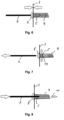
Fig. 3 bis 8 zeigen das erfindungsgemäße Verfahren in Einzelschritten. -
Fig. 3 zeigt die für den Sensor/Schlauchanschluss zu durchdringende Wand 3. - In
Fig. 4 ist durch den Pfeil das Herstellen eines Lochs 4 durch die Wand 3 mit dem Durchmesser des Nietfortsatzes 5 eines Blindniets 6 mit Dorn 7 verdeutlicht. -
Fig. 5 zeigt das Durchstecken des Blindniets 6 durch das Loch 4 bis zum Anschlag - siehe hierzu auchFig. 6 - des Nietkopfes 8 an der Wand 3 und Aufstecken eines Schlauchs 9 mit einem Innendurchmesser der dem Außendurchmesser des Nietfortsatzes 5 entspricht auf den Nietfortsatz 5 des Blindniets 6 auf der gegenüberliegen Seite der Wandung 3. -
Fig. 7 zeigt das Ziehen des Dorns 7 des Blindniets 6 in Pfeilrichtung unter Abriss des Abschlussteils 10 des Dorns 7. Das Ziehen kann mit einer normalen Blindnietzange erfolgen. Dabei erfolgt eine Ausdehnung des Nietfortsatzes 5 im Bereich des aufgesetzten Schlauches 9. Der Abschlussteil 10 des Blindniets kann gegebenenfalls nach Abriss des Dorns 7 zunächst im geweiteten Bereich des Niets verbleiben und muss in diesem anschließend entfernt werden. - Schließlich erfolgt nur noch, wie in
Fig. 8 gezeigt, das Durchstoßen des Abschlussteils 10 des Dorns 7 des Blindniets 6 in Richtung des aufgesetzten Schlauchs 9. Hierzu kann z.B. auch der zuvor mit Hilfe der Nietzange abgerissene Dorn 7 zusammen mit leichten Hammerschlägen verwendet werden. - Nach Entnahme des Abschlussteils 10 aus dem Schlauch 9 ist die Schlauchverbindung durch die Wandung 3 der Einströmdüse für einen Drucksensor fertig gestellt. Nach Abschluss der Arbeiten bleibt der aerodynamisch hervorragend ausgebildete Nietkopf 8 im luftdurchströmten Bereich stehen. Der angebrachte Schlauch 9 hält ohne Kleber oder weitere Befestigungsmaßnahmen.
-
Fig. 9 zeigt den Schlauchanschlusses 1 mit Nietkopf 8 im laufenden Betrieb zur Messung eines Luftstroms 11 durch den Luftkanal 12 und den Schlauch 9. -
- 1
- Schlauchanschluss
- 2
- Druckmesspunkt
- 3
- Wand
- 4
- Loch
- 5
- Nietfortsatz
- 6
- Blindniet
- 7
- Dorn
- 8
- Nietkopf
- 9
- Schlauch
- 10
- Abschlussteil
- 11
- Luftströmung
- 12
- Luftkanal
Claims (2)
- Verfahren zur Herstellung eines Schlauchanschlusses (1) mit Druckmesspunkt zum Anschluss für einen Drucksensor durch eine geschlossene Wand (3),
gekennzeichnet durch die folgenden Verfahrensschritte:- Herstellen eines Lochs (4) durch die Wand (3) mit dem Durchmesser des Nietfortsatzes (5) eines Blindniets (6) mit Dorn (7),- Durchstecken des Blindniets (6) durch das Loch (4) bis zum Anschlag des Nietkopfes (8) an der Wand (3) und Aufstecken eines Schlauchs (9) mit einem Innendurchmesser, der dem Außendurchmesser des Nietfortsatzes (5) entspricht, auf den Nietfortsatz (5) des Blindniets (6) auf der gegenüberliegen Seite der Wandung (3),- Ziehen des Dorns (7) des Blindniets (6). - Verfahren nach Anspruch 1,
dadurch gekennzeichnet,
dass nach dem Ziehen des Dorns (7) ein Durchstoßen des Abschlussteils (10) des Dorns (7) des Blindniets (6) in Richtung des aufgesetzten Schlauchs (9) erfolgt.
Applications Claiming Priority (2)
| Application Number | Priority Date | Filing Date | Title |
|---|---|---|---|
| DE102015119086.9A DE102015119086B4 (de) | 2015-11-06 | 2015-11-06 | Verfahren zur Herstellung eines Schlauchanschlusses mit Druckmesspunkt für einen Drucksensor |
| PCT/DE2016/100519 WO2017076394A1 (de) | 2015-11-06 | 2016-11-03 | Verfahren zur herstellung eines schlauchanschlusses mit druckmesspunkt für einen drucksensor |
Publications (3)
| Publication Number | Publication Date |
|---|---|
| EP3371501A1 EP3371501A1 (de) | 2018-09-12 |
| EP3371501C0 EP3371501C0 (de) | 2023-06-07 |
| EP3371501B1 true EP3371501B1 (de) | 2023-06-07 |
Family
ID=57354039
Family Applications (1)
| Application Number | Title | Priority Date | Filing Date |
|---|---|---|---|
| EP16798392.3A Active EP3371501B1 (de) | 2015-11-06 | 2016-11-03 | Verfahren zur herstellung eines schlauchanschlusses mit druckmesspunkt für einen drucksensor |
Country Status (9)
| Country | Link |
|---|---|
| US (1) | US20180259107A1 (de) |
| EP (1) | EP3371501B1 (de) |
| CN (1) | CN108138991B (de) |
| CA (1) | CA3002135A1 (de) |
| CH (1) | CH713336B1 (de) |
| DE (2) | DE102015119086B4 (de) |
| MX (1) | MX2018005559A (de) |
| RU (1) | RU2708192C1 (de) |
| WO (1) | WO2017076394A1 (de) |
Citations (2)
| Publication number | Priority date | Publication date | Assignee | Title |
|---|---|---|---|---|
| US4152818A (en) * | 1977-07-14 | 1979-05-08 | United Aircraft Products, Inc. | Making mechanical tube joints |
| US4929001A (en) * | 1989-06-02 | 1990-05-29 | The B.F. Goodrich Company | Tubular connector |
Family Cites Families (11)
| Publication number | Priority date | Publication date | Assignee | Title |
|---|---|---|---|---|
| NL7409510A (nl) * | 1974-07-15 | 1976-01-19 | Ultra Centrifuge Nederland Nv | Doorvoer voor een fluidumstroom. |
| JPS5550367U (de) * | 1978-09-29 | 1980-04-02 | ||
| DE3328913A1 (de) * | 1983-08-10 | 1985-02-28 | Körting Hannover AG, 3000 Hannover | Einrichtung zur befestigung eines rohres in einer bohrung |
| DE3619826A1 (de) * | 1986-06-12 | 1987-12-17 | Hirschmann Radiotechnik | Nietverbindung |
| RU2101603C1 (ru) * | 1995-08-04 | 1998-01-10 | Российский Федеральный Ядерный Центр - Всероссийский Научно-Исследовательский Институт Экспериментальной Физики | Соединение труб через отверстие в стенке |
| US5741099A (en) * | 1996-05-17 | 1998-04-21 | Asar Group, Inc. | Self tapping blind setting rivet assembly |
| US5915901A (en) * | 1996-07-12 | 1999-06-29 | Asar Group, Inc. | Blind setting rivet assembly |
| DE10162063B4 (de) * | 2001-01-30 | 2005-12-22 | Klaus Wirth | Blindniet, Verfahren zur Herstellung eines Blindniets, Verfahren zur Durchführung einer Nietverbindung |
| CN2849737Y (zh) * | 2005-11-07 | 2006-12-20 | 国网北京电力建设研究院 | 高压抽能供电的送电线路微风振动监测装置 |
| DE102013001124B3 (de) * | 2013-01-23 | 2014-07-17 | Gesipa Blindniettechnik Gmbh | Schlauchanschlussanordnung |
| CN204521949U (zh) * | 2015-04-16 | 2015-08-05 | 陈晓丽 | 一种治疗不孕不育宫颈扩张器 |
-
2015
- 2015-11-06 DE DE102015119086.9A patent/DE102015119086B4/de active Active
-
2016
- 2016-11-03 MX MX2018005559A patent/MX2018005559A/es unknown
- 2016-11-03 DE DE112016005093.3T patent/DE112016005093A5/de not_active Withdrawn
- 2016-11-03 EP EP16798392.3A patent/EP3371501B1/de active Active
- 2016-11-03 WO PCT/DE2016/100519 patent/WO2017076394A1/de not_active Ceased
- 2016-11-03 US US15/770,777 patent/US20180259107A1/en not_active Abandoned
- 2016-11-03 CA CA3002135A patent/CA3002135A1/en not_active Abandoned
- 2016-11-03 CN CN201680059182.7A patent/CN108138991B/zh active Active
- 2016-11-03 CH CH00554/18A patent/CH713336B1/de not_active IP Right Cessation
- 2016-11-03 RU RU2018119928A patent/RU2708192C1/ru active
Patent Citations (2)
| Publication number | Priority date | Publication date | Assignee | Title |
|---|---|---|---|---|
| US4152818A (en) * | 1977-07-14 | 1979-05-08 | United Aircraft Products, Inc. | Making mechanical tube joints |
| US4929001A (en) * | 1989-06-02 | 1990-05-29 | The B.F. Goodrich Company | Tubular connector |
Also Published As
| Publication number | Publication date |
|---|---|
| CA3002135A1 (en) | 2017-05-11 |
| WO2017076394A1 (de) | 2017-05-11 |
| CN108138991A (zh) | 2018-06-08 |
| MX2018005559A (es) | 2018-08-15 |
| US20180259107A1 (en) | 2018-09-13 |
| RU2708192C1 (ru) | 2019-12-04 |
| CH713336B1 (de) | 2020-11-30 |
| DE102015119086B4 (de) | 2018-05-24 |
| EP3371501C0 (de) | 2023-06-07 |
| EP3371501A1 (de) | 2018-09-12 |
| CN108138991B (zh) | 2020-08-18 |
| DE102015119086A1 (de) | 2017-05-11 |
| DE112016005093A5 (de) | 2018-07-26 |
Similar Documents
| Publication | Publication Date | Title |
|---|---|---|
| EP2542813B1 (de) | Verfahren bei dem ein leitungsverbinder von einer befestigungsvorrichtung an einer leitung für flüssige und/oder gasförmige medien befestigt wird | |
| DE102014106141A1 (de) | Anschlusstülle für ein Schrader-Ventil (amerikanisch) / Presta-Ventil (französisch) | |
| WO2010108662A1 (de) | Fluidtechnisches gerät, insbesondere greifervorrichtung | |
| DE69612907T2 (de) | Ziehdornlängenmesssystem für ein Blindnietsetzgerät | |
| DE102008001908A1 (de) | Vorrichtung zur Bohrlochreinigung | |
| DE102015119086B4 (de) | Verfahren zur Herstellung eines Schlauchanschlusses mit Druckmesspunkt für einen Drucksensor | |
| EP3296058A2 (de) | Bohrlochreinigungsvorrichtung | |
| DE102010025524A1 (de) | Vorrichtung zum Erzeugen eines hohlen Kunststoffprofiles | |
| DE102014208513B4 (de) | Verfahren zur Befestigung mehrerer Werkstücke mittels eines hohlen Nietelements | |
| DE102013219217A1 (de) | Tragbare Vorrichtung zum Herstellen von Nietverbindungen zwischen Werkstücken | |
| EP2687768A2 (de) | Vorrichtung zur Entnahme von Fluid aus einer Rohrleitung | |
| EP3724555B1 (de) | Lüftungsgerät und verfahren zu dessen montage und demontage | |
| EP1210213B1 (de) | Mittel zum wechseln von handschuhen | |
| WO2017097698A1 (de) | Anschlussvorrichtung | |
| DE102017207053A1 (de) | Abgasrohr sowie Verfahren zum Ablängen eines Abgasrohres | |
| DE3704130C2 (de) | Gasbeheizter Wassererhitzer mit einer geschlossenen Verbrennungskammer | |
| EP3102342A1 (de) | Reinigungssatz und -verfahren für einen klimakanal | |
| EP3318356A1 (de) | Rohrschere | |
| DE2015656B2 (de) | Vorrichtung zum Herstellen einer Verbindungsmuffe | |
| CN204382184U (zh) | 过滤组件的滤芯安装工具 | |
| AT509261B1 (de) | Verfahren und vorrichtung zum aufnehmen von kleinteilen | |
| DE202006005917U1 (de) | Vorrichtung zum Absaugen von Gasen | |
| EP2146773B1 (de) | Verfahren zur Herstellung einer Rohr- und Schlauchverbindung | |
| EP1598485A2 (de) | Vorrichtung zum Evakuieren eines Steigleitungsrohres | |
| EP2117737A1 (de) | Verfahren zum wechseln von filtern |
Legal Events
| Date | Code | Title | Description |
|---|---|---|---|
| STAA | Information on the status of an ep patent application or granted ep patent |
Free format text: STATUS: UNKNOWN |
|
| STAA | Information on the status of an ep patent application or granted ep patent |
Free format text: STATUS: THE INTERNATIONAL PUBLICATION HAS BEEN MADE |
|
| PUAI | Public reference made under article 153(3) epc to a published international application that has entered the european phase |
Free format text: ORIGINAL CODE: 0009012 |
|
| STAA | Information on the status of an ep patent application or granted ep patent |
Free format text: STATUS: REQUEST FOR EXAMINATION WAS MADE |
|
| 17P | Request for examination filed |
Effective date: 20180328 |
|
| AK | Designated contracting states |
Kind code of ref document: A1 Designated state(s): AL AT BE BG CH CY CZ DE DK EE ES FI FR GB GR HR HU IE IS IT LI LT LU LV MC MK MT NL NO PL PT RO RS SE SI SK SM TR |
|
| AX | Request for extension of the european patent |
Extension state: BA ME |
|
| DAV | Request for validation of the european patent (deleted) | ||
| DAX | Request for extension of the european patent (deleted) | ||
| STAA | Information on the status of an ep patent application or granted ep patent |
Free format text: STATUS: EXAMINATION IS IN PROGRESS |
|
| 17Q | First examination report despatched |
Effective date: 20210330 |
|
| GRAP | Despatch of communication of intention to grant a patent |
Free format text: ORIGINAL CODE: EPIDOSNIGR1 |
|
| STAA | Information on the status of an ep patent application or granted ep patent |
Free format text: STATUS: GRANT OF PATENT IS INTENDED |
|
| RIC1 | Information provided on ipc code assigned before grant |
Ipc: F24F 11/62 20180101ALI20220915BHEP Ipc: F24F 11/30 20180101ALI20220915BHEP Ipc: F16L 33/213 20060101ALI20220915BHEP Ipc: F16B 19/10 20060101ALI20220915BHEP Ipc: F16L 41/00 20060101ALI20220915BHEP Ipc: F16L 41/08 20060101ALI20220915BHEP Ipc: F16L 5/00 20060101AFI20220915BHEP |
|
| INTG | Intention to grant announced |
Effective date: 20221014 |
|
| GRAS | Grant fee paid |
Free format text: ORIGINAL CODE: EPIDOSNIGR3 |
|
| GRAA | (expected) grant |
Free format text: ORIGINAL CODE: 0009210 |
|
| STAA | Information on the status of an ep patent application or granted ep patent |
Free format text: STATUS: THE PATENT HAS BEEN GRANTED |
|
| AK | Designated contracting states |
Kind code of ref document: B1 Designated state(s): AL AT BE BG CH CY CZ DE DK EE ES FI FR GB GR HR HU IE IS IT LI LT LU LV MC MK MT NL NO PL PT RO RS SE SI SK SM TR |
|
| REG | Reference to a national code |
Ref country code: GB Ref legal event code: FG4D Free format text: NOT ENGLISH |
|
| REG | Reference to a national code |
Ref country code: CH Ref legal event code: EP Ref country code: AT Ref legal event code: REF Ref document number: 1576003 Country of ref document: AT Kind code of ref document: T Effective date: 20230615 |
|
| REG | Reference to a national code |
Ref country code: DE Ref legal event code: R096 Ref document number: 502016015845 Country of ref document: DE |
|
| U01 | Request for unitary effect filed |
Effective date: 20230705 |
|
| U07 | Unitary effect registered |
Designated state(s): AT BE BG DE DK EE FI FR IT LT LU LV MT NL PT SE SI Effective date: 20230714 |
|
| REG | Reference to a national code |
Ref country code: LT Ref legal event code: MG9D |
|
| PG25 | Lapsed in a contracting state [announced via postgrant information from national office to epo] |
Ref country code: NO Free format text: LAPSE BECAUSE OF FAILURE TO SUBMIT A TRANSLATION OF THE DESCRIPTION OR TO PAY THE FEE WITHIN THE PRESCRIBED TIME-LIMIT Effective date: 20230907 Ref country code: ES Free format text: LAPSE BECAUSE OF FAILURE TO SUBMIT A TRANSLATION OF THE DESCRIPTION OR TO PAY THE FEE WITHIN THE PRESCRIBED TIME-LIMIT Effective date: 20230607 |
|
| PG25 | Lapsed in a contracting state [announced via postgrant information from national office to epo] |
Ref country code: RS Free format text: LAPSE BECAUSE OF FAILURE TO SUBMIT A TRANSLATION OF THE DESCRIPTION OR TO PAY THE FEE WITHIN THE PRESCRIBED TIME-LIMIT Effective date: 20230607 Ref country code: HR Free format text: LAPSE BECAUSE OF FAILURE TO SUBMIT A TRANSLATION OF THE DESCRIPTION OR TO PAY THE FEE WITHIN THE PRESCRIBED TIME-LIMIT Effective date: 20230607 Ref country code: GR Free format text: LAPSE BECAUSE OF FAILURE TO SUBMIT A TRANSLATION OF THE DESCRIPTION OR TO PAY THE FEE WITHIN THE PRESCRIBED TIME-LIMIT Effective date: 20230908 |
|
| U20 | Renewal fee for the european patent with unitary effect paid |
Year of fee payment: 8 Effective date: 20231120 |
|
| PG25 | Lapsed in a contracting state [announced via postgrant information from national office to epo] |
Ref country code: SK Free format text: LAPSE BECAUSE OF FAILURE TO SUBMIT A TRANSLATION OF THE DESCRIPTION OR TO PAY THE FEE WITHIN THE PRESCRIBED TIME-LIMIT Effective date: 20230607 |
|
| PG25 | Lapsed in a contracting state [announced via postgrant information from national office to epo] |
Ref country code: IS Free format text: LAPSE BECAUSE OF FAILURE TO SUBMIT A TRANSLATION OF THE DESCRIPTION OR TO PAY THE FEE WITHIN THE PRESCRIBED TIME-LIMIT Effective date: 20231007 |
|
| PG25 | Lapsed in a contracting state [announced via postgrant information from national office to epo] |
Ref country code: SM Free format text: LAPSE BECAUSE OF FAILURE TO SUBMIT A TRANSLATION OF THE DESCRIPTION OR TO PAY THE FEE WITHIN THE PRESCRIBED TIME-LIMIT Effective date: 20230607 Ref country code: SK Free format text: LAPSE BECAUSE OF FAILURE TO SUBMIT A TRANSLATION OF THE DESCRIPTION OR TO PAY THE FEE WITHIN THE PRESCRIBED TIME-LIMIT Effective date: 20230607 Ref country code: RO Free format text: LAPSE BECAUSE OF FAILURE TO SUBMIT A TRANSLATION OF THE DESCRIPTION OR TO PAY THE FEE WITHIN THE PRESCRIBED TIME-LIMIT Effective date: 20230607 Ref country code: IS Free format text: LAPSE BECAUSE OF FAILURE TO SUBMIT A TRANSLATION OF THE DESCRIPTION OR TO PAY THE FEE WITHIN THE PRESCRIBED TIME-LIMIT Effective date: 20231007 Ref country code: CZ Free format text: LAPSE BECAUSE OF FAILURE TO SUBMIT A TRANSLATION OF THE DESCRIPTION OR TO PAY THE FEE WITHIN THE PRESCRIBED TIME-LIMIT Effective date: 20230607 |
|
| PG25 | Lapsed in a contracting state [announced via postgrant information from national office to epo] |
Ref country code: PL Free format text: LAPSE BECAUSE OF FAILURE TO SUBMIT A TRANSLATION OF THE DESCRIPTION OR TO PAY THE FEE WITHIN THE PRESCRIBED TIME-LIMIT Effective date: 20230607 |
|
| REG | Reference to a national code |
Ref country code: DE Ref legal event code: R097 Ref document number: 502016015845 Country of ref document: DE |
|
| PLBE | No opposition filed within time limit |
Free format text: ORIGINAL CODE: 0009261 |
|
| STAA | Information on the status of an ep patent application or granted ep patent |
Free format text: STATUS: NO OPPOSITION FILED WITHIN TIME LIMIT |
|
| 26N | No opposition filed |
Effective date: 20240308 |
|
| PG25 | Lapsed in a contracting state [announced via postgrant information from national office to epo] |
Ref country code: MC Free format text: LAPSE BECAUSE OF FAILURE TO SUBMIT A TRANSLATION OF THE DESCRIPTION OR TO PAY THE FEE WITHIN THE PRESCRIBED TIME-LIMIT Effective date: 20230607 |
|
| PG25 | Lapsed in a contracting state [announced via postgrant information from national office to epo] |
Ref country code: MC Free format text: LAPSE BECAUSE OF FAILURE TO SUBMIT A TRANSLATION OF THE DESCRIPTION OR TO PAY THE FEE WITHIN THE PRESCRIBED TIME-LIMIT Effective date: 20230607 |
|
| REG | Reference to a national code |
Ref country code: IE Ref legal event code: MM4A |
|
| PG25 | Lapsed in a contracting state [announced via postgrant information from national office to epo] |
Ref country code: IE Free format text: LAPSE BECAUSE OF NON-PAYMENT OF DUE FEES Effective date: 20231103 |
|
| PG25 | Lapsed in a contracting state [announced via postgrant information from national office to epo] |
Ref country code: IE Free format text: LAPSE BECAUSE OF NON-PAYMENT OF DUE FEES Effective date: 20231103 |
|
| U20 | Renewal fee for the european patent with unitary effect paid |
Year of fee payment: 9 Effective date: 20241126 |
|
| PG25 | Lapsed in a contracting state [announced via postgrant information from national office to epo] |
Ref country code: CY Free format text: LAPSE BECAUSE OF FAILURE TO SUBMIT A TRANSLATION OF THE DESCRIPTION OR TO PAY THE FEE WITHIN THE PRESCRIBED TIME-LIMIT; INVALID AB INITIO Effective date: 20161103 |
|
| PG25 | Lapsed in a contracting state [announced via postgrant information from national office to epo] |
Ref country code: HU Free format text: LAPSE BECAUSE OF FAILURE TO SUBMIT A TRANSLATION OF THE DESCRIPTION OR TO PAY THE FEE WITHIN THE PRESCRIBED TIME-LIMIT; INVALID AB INITIO Effective date: 20161103 |
|
| REG | Reference to a national code |
Ref country code: CH Ref legal event code: U11 Free format text: ST27 STATUS EVENT CODE: U-0-0-U10-U11 (AS PROVIDED BY THE NATIONAL OFFICE) Effective date: 20251201 |
|
| U20 | Renewal fee for the european patent with unitary effect paid |
Year of fee payment: 10 Effective date: 20251112 |
|
| PGFP | Annual fee paid to national office [announced via postgrant information from national office to epo] |
Ref country code: GB Payment date: 20251121 Year of fee payment: 10 |
|
| PGFP | Annual fee paid to national office [announced via postgrant information from national office to epo] |
Ref country code: TR Payment date: 20251031 Year of fee payment: 10 |
|
| PGFP | Annual fee paid to national office [announced via postgrant information from national office to epo] |
Ref country code: CH Payment date: 20251201 Year of fee payment: 10 |
|
| U1N | Appointed representative for the unitary patent procedure changed after the registration of the unitary effect |
Representative=s name: AURODION PARTMBB; DE |