EP3371451B1 - Hydrogerät - Google Patents
Hydrogerät Download PDFInfo
- Publication number
- EP3371451B1 EP3371451B1 EP16791390.4A EP16791390A EP3371451B1 EP 3371451 B1 EP3371451 B1 EP 3371451B1 EP 16791390 A EP16791390 A EP 16791390A EP 3371451 B1 EP3371451 B1 EP 3371451B1
- Authority
- EP
- European Patent Office
- Prior art keywords
- hydraulic
- pump
- motor
- tank
- circuit board
- Prior art date
- Legal status (The legal status is an assumption and is not a legal conclusion. Google has not performed a legal analysis and makes no representation as to the accuracy of the status listed.)
- Active
Links
Images




Classifications
-
- F—MECHANICAL ENGINEERING; LIGHTING; HEATING; WEAPONS; BLASTING
- F04—POSITIVE - DISPLACEMENT MACHINES FOR LIQUIDS; PUMPS FOR LIQUIDS OR ELASTIC FLUIDS
- F04B—POSITIVE-DISPLACEMENT MACHINES FOR LIQUIDS; PUMPS
- F04B23/00—Pumping installations or systems
- F04B23/02—Pumping installations or systems having reservoirs
- F04B23/025—Pumping installations or systems having reservoirs the pump being located directly adjacent the reservoir
- F04B23/028—Pumping installations or systems having reservoirs the pump being located directly adjacent the reservoir the pump being mounted on top of the reservoir
-
- F—MECHANICAL ENGINEERING; LIGHTING; HEATING; WEAPONS; BLASTING
- F04—POSITIVE - DISPLACEMENT MACHINES FOR LIQUIDS; PUMPS FOR LIQUIDS OR ELASTIC FLUIDS
- F04B—POSITIVE-DISPLACEMENT MACHINES FOR LIQUIDS; PUMPS
- F04B17/00—Pumps characterised by combination with, or adaptation to, specific driving engines or motors
- F04B17/03—Pumps characterised by combination with, or adaptation to, specific driving engines or motors driven by electric motors
-
- F—MECHANICAL ENGINEERING; LIGHTING; HEATING; WEAPONS; BLASTING
- F04—POSITIVE - DISPLACEMENT MACHINES FOR LIQUIDS; PUMPS FOR LIQUIDS OR ELASTIC FLUIDS
- F04B—POSITIVE-DISPLACEMENT MACHINES FOR LIQUIDS; PUMPS
- F04B23/00—Pumping installations or systems
- F04B23/02—Pumping installations or systems having reservoirs
-
- F—MECHANICAL ENGINEERING; LIGHTING; HEATING; WEAPONS; BLASTING
- F04—POSITIVE - DISPLACEMENT MACHINES FOR LIQUIDS; PUMPS FOR LIQUIDS OR ELASTIC FLUIDS
- F04B—POSITIVE-DISPLACEMENT MACHINES FOR LIQUIDS; PUMPS
- F04B23/00—Pumping installations or systems
- F04B23/02—Pumping installations or systems having reservoirs
- F04B23/025—Pumping installations or systems having reservoirs the pump being located directly adjacent the reservoir
-
- F—MECHANICAL ENGINEERING; LIGHTING; HEATING; WEAPONS; BLASTING
- F15—FLUID-PRESSURE ACTUATORS; HYDRAULICS OR PNEUMATICS IN GENERAL
- F15B—SYSTEMS ACTING BY MEANS OF FLUIDS IN GENERAL; FLUID-PRESSURE ACTUATORS, e.g. SERVOMOTORS; DETAILS OF FLUID-PRESSURE SYSTEMS, NOT OTHERWISE PROVIDED FOR
- F15B1/00—Installations or systems with accumulators; Supply reservoir or sump assemblies
- F15B1/26—Supply reservoir or sump assemblies
-
- F—MECHANICAL ENGINEERING; LIGHTING; HEATING; WEAPONS; BLASTING
- F15—FLUID-PRESSURE ACTUATORS; HYDRAULICS OR PNEUMATICS IN GENERAL
- F15B—SYSTEMS ACTING BY MEANS OF FLUIDS IN GENERAL; FLUID-PRESSURE ACTUATORS, e.g. SERVOMOTORS; DETAILS OF FLUID-PRESSURE SYSTEMS, NOT OTHERWISE PROVIDED FOR
- F15B13/00—Details of servomotor systems ; Valves for servomotor systems
- F15B13/02—Fluid distribution or supply devices characterised by their adaptation to the control of servomotors
- F15B13/06—Fluid distribution or supply devices characterised by their adaptation to the control of servomotors for use with two or more servomotors
- F15B13/08—Assemblies of units, each for the control of a single servomotor only
- F15B13/0803—Modular units
- F15B13/0807—Manifolds
- F15B13/0814—Monoblock manifolds
-
- F—MECHANICAL ENGINEERING; LIGHTING; HEATING; WEAPONS; BLASTING
- F04—POSITIVE - DISPLACEMENT MACHINES FOR LIQUIDS; PUMPS FOR LIQUIDS OR ELASTIC FLUIDS
- F04B—POSITIVE-DISPLACEMENT MACHINES FOR LIQUIDS; PUMPS
- F04B53/00—Component parts, details or accessories not provided for in, or of interest apart from, groups F04B1/00 - F04B23/00 or F04B39/00 - F04B47/00
- F04B53/10—Valves; Arrangement of valves
- F04B53/1095—Valves linked to another valve of another pumping chamber
-
- F—MECHANICAL ENGINEERING; LIGHTING; HEATING; WEAPONS; BLASTING
- F04—POSITIVE - DISPLACEMENT MACHINES FOR LIQUIDS; PUMPS FOR LIQUIDS OR ELASTIC FLUIDS
- F04C—ROTARY-PISTON, OR OSCILLATING-PISTON, POSITIVE-DISPLACEMENT MACHINES FOR LIQUIDS; ROTARY-PISTON, OR OSCILLATING-PISTON, POSITIVE-DISPLACEMENT PUMPS
- F04C11/00—Combinations of two or more machines or pumps, each being of rotary-piston or oscillating-piston type; Pumping installations
- F04C11/008—Enclosed motor pump units
Definitions
- the present invention relates to a hydraulic device for a rail vehicle and in particular to an optimized arrangement of a motor-pump unit in hydraulic devices for rail vehicles.
- a hydraulic device is a hydraulic control and supply unit that provides a controlled or regulated hydraulic flow for various components of the corresponding rail vehicle.
- controllable valves can be formed in the hydraulic devices, which selectively activate or deactivate certain hydraulic lines in order to produce a volume flow there, wherein the hydraulic devices can be controlled via a vehicle control unit.
- Hydraulic devices generally consist of three main components: a control area with a control cover, an interconnection board (control plate) and a tank area with a tank for a hydraulic fluid.
- a motor and a pump usually couple to the control plate in order to pump the hydraulic fluid into the control plate.
- Hydro devices are in the prior art, for example in DE 196 12 582 A1 described.
- the document describes a drive unit for a vehicle in which a hydraulic pump and an electric motor are housed within a hydraulic tank. Among other things, this is advantageous for sound absorption and for simultaneously achieving improved explosion protection.
- the publication GB 1399071 describes the advantageous arrangement of the motor and pump in an injection molding system, through which a reduction in the noise level during operation can be achieved.
- Fig. 6 shows a first conventional hydraulic device for rail vehicles. It consists of a control area 440, a hydraulic circuit board 430 and a tank area 410. A pump 124 is arranged in the tank area 410 and a motor 122 is arranged in the control area 440. The motor 122 is connected to the pump 124 on the opposite side of the hydraulic circuit board 430 via a bushing 460 through the hydraulic circuit board 430.
- the motor 122 and the pump 124 can have a common shaft that is passed directly through the bushing 460.
- the pump 124 draws a liquid from the tank area 410 and pumps the hydraulic liquid through connecting channels (not in the Fig. 6 shown) in the hydraulic circuit board 430.
- Various electrical or hydraulic components can also be formed on the hydraulic circuit board 430, which are electrically controlled or electrically supplied via the control region 440 (or via the tank region).
- FIG. 4 shows a further conventional hydraulic device 500 with a tank area 510, a control unit 540 with integrated hydraulic circuit board 530 and an external motor-pump combination 122, 124, which is connected to the hydraulic circuit board 530 and to the tank area 510 via at least one fluid channel 520 Pump hydraulic fluid from the tank area 510 into the hydraulic circuit board 530.
- a motor flange 525 is also provided to hold the motor-pump combination 122, 124.
- the hydraulic devices shown have the following disadvantages.
- the motor-pump combination 122, 124 takes up a lot of space on the control plate 430.
- fewer components can be arranged on the control plate 430.
- the passage 460 of the motor and pump shaft requires a breakthrough through the control plate 430. This breakthrough considerably reduces the control plate cross-section that can be used for the interconnection of the components and leads to complex designs for the connecting bores between the control plate 430 and the attached components (in FIGS Fig. 6 and 7 Not shown).
- the special hydro device like it Fig.
- control plate 530 shows, although there is a separation between the control plate 530 and the attachment of the motor-pump combination 122, 124, they require their own motor flange 525 and connecting elements 520 for transferring the volume flow from the motor flange 525 to the control plate 540, 530.
- the present invention solves the above-mentioned technical problem by means of a hydraulic device according to claim 1.
- the dependent claims relate to further advantageous developments.
- the present invention relates to a hydraulic device for a rail vehicle, the hydraulic device comprising a tank area for a hydraulic fluid, a motor with a pump for pumping the hydraulic fluid, a hydraulic circuit board for providing hydraulic fluid paths and for receiving hydraulic components, and a control area for actuation the hydraulic components.
- the tank area and the control area are arranged on opposite sides of the hydraulic circuit board, and the motor is arranged together with the pump on one side of the hydraulic circuit board.
- the hydraulic device is characterized in that it further comprises a holding structure for holding the motor and the pump and the holding structure is held in the tank area and is coupled to the hydraulic circuit board, the motor and the pump not coupling directly to the hydraulic circuit board, but through the holding structure can be held independently of the hydraulic circuit board.
- a liquid path is to be understood to mean all cavities through which a hydraulic liquid can be passed.
- the hydraulic fluid paths mentioned comprise, on the one hand, hydraulic lines which are led to the outside, but also fluid connections which are formed within the hydraulic circuit board and, for example, provide a connection from the pump to an exemplary valve.
- the hydraulic circuit board can, for example, be arranged in the housing in such a way that it separates the housing into two separate areas (the tank area and the control area).
- a hydraulic control and supply unit (hydraulic device) which has an identical functionality compared to the conventional hydraulic devices, but the necessary installation space when implemented reduced or allowed in their implementation more functions that can be implemented in the installation space.
- the hydraulic components comprise at least one valve and / or at least one sensor, which are electrically controllable.
- the control area can be designed as a cover and have a connection unit.
- the control area can also include an electrical circuit that interconnects the electrically controllable hydraulic components with the connection unit, so that the hydraulic components can be controlled from outside the housing.
- the pump is arranged between the motor and the hydraulic circuit board.
- the motor can also be arranged between the pump and the hydraulic circuit board.
- An advantage of the first version is that the hydraulic fluid can be pumped directly from the pump into the hydraulic circuit board without the need for additional fluid lines.
- An advantage of the second version is that the motor is securely held by the hydraulic circuit board, so that a mechanically more stable construction can be achieved, in particular if the motor is larger than the pump.
- the pump and the motor comprise a common or two coupled rotary shaft (s), the rotary shaft (s) being / are spaced apart from the hydraulic circuit board.
- the rotary shaft of the pump and / or the rotary shaft of the motor do not couple to the hydraulic circuit board and thus cannot directly transmit vibrations to the hydraulic circuit board.
- an intermediate space is formed between the rotary shaft (s) that suppresses the exemplary negative influences of vibrations on sensors or similar components.
- the pump is arranged together with the motor in the tank area.
- An advantage of this embodiment is that the motor can be cooled together with the pump by the liquid in the tank.
- a very efficient volume utilization is achieved as a result, since the tank volume only has to be increased to the extent that the volume of the combination of pump and motor comprises together.
- the tank area comprises a tank for storing the hydraulic fluid and the pump is accommodated in the tank together with the motor.
- the hydraulic device comprises a holding structure for holding the motor and / or the pump.
- the holding structure is held in the control area or in the tank area and couples to the hydraulic circuit board.
- the holding structure is part of the tank area or part of the control area.
- the holding structure couples to the hydraulic circuit board or the pump is connected to the hydraulic circuit board via a line.
- the tank area comprises a tank housing and the control area comprises a cover, wherein the holding structure can be attached to the tank housing or the cover.
- the pump is arranged in the tank area and the motor is fastened to an outer wall of the tank area.
- the motor and the pump are optionally arranged on the hydraulic circuit board next to the tank area.
- Another embodiment which is not the subject of the present invention, also relates to a hydraulic device for a rail vehicle with a tank area for a hydraulic fluid, a hydraulic circuit board for providing hydraulic fluid paths and for receiving hydraulic components and a control area for controlling the hydraulic Components, wherein the tank area and the control area are arranged on opposite sides of the hydraulic circuit board.
- this hydraulic device comprises a pump for pumping the hydraulic fluid, which is arranged in the tank area.
- An attachment option is optionally provided on the tank area in order to attach a motor for operating the pump to an outer surface of the tank area.
- the present invention also relates to a rail vehicle with one of the hydraulic devices described above.
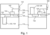
- Fig. 1 shows a hydraulic device for a rail vehicle, the hydraulic device comprising the following components: a tank area 110 for a hydraulic fluid (not shown), a motor 122 with a pump 124 for pumping the hydraulic fluid, a hydraulic circuit board 130 for providing hydraulic fluid paths 132 , 133 and to accommodate hydraulic Components 134, a control area 140 for controlling the hydraulic components 134 and a housing 150.
- the tank area 110, the hydraulic circuit board 130 and the control area 140 are accommodated in the housing 150, the tank area 110 and the control area 140 on opposite sides and the motor 122 is arranged together with the pump 124 on one side of the hydraulic circuit board 130.
- the motor 122 On the left side of the Fig. 1 the motor 122 is arranged together with the pump 124 in the tank area 110, while on the right side the motor 122 with the pump 124 is arranged in the control area 140.
- the hydraulic components 134 can comprise, for example, valves and / or sensors that open or close the hydraulic flow paths 132, 133 or take measurements on the hydraulic fluid (for example pressure measurements).
- the hydraulic flow paths 132, 133 can be internal flow paths 132 between the components on the hydraulic circuit board 130 or else further hydraulic flow paths 133 that couple to an external hydraulic line (outside the housing).
- the valves can be, for example, electromagnetically controlled valves which are connected to a connection unit 144 via an electrical line 142, the connection unit 144 establishing a connection between the inner region of the housing 150 and the outer region.
- the hydraulic device can be electrically controlled by a control unit of the rail vehicle via the connection unit 144, for example to read sensor data from the sensors or to control the valves via corresponding signals.
- the hydraulic circuit board 130 divides the interior of the housing 150 into two sections, for example.
- the tank area 110 which in particular comprises the tank itself, is accommodated in one section, while the control area 140 is formed in the other area.
- the motor 122 together with the pump 124 can, for example, be arranged directly in the tank (see left side of FIG Fig. 1 ) so that the hydraulic fluid can flow around it. This offers the advantage that the hydraulic fluid is also used for cooling provides the motor 122 as well as for the pump 124.
- the accommodation of the motor 122 and the pump 124 in the tank area 110 also offers the advantage that more space is available in the control area 140 for additional or further hydraulic or non-hydraulic components.
- the control area 140 can, however, also be selected to be correspondingly smaller.
- the additional space required in the tank area 110 which must also be available due to the introduction of the motor 122 and the pump 124, is only limited to the volume of the motor 122 and the volume of the pump 124 itself, so that an additional additional space is required a minimum is limited.
- Moving the engine to the tank area can also reduce the height of the control cover.
- the tank cap can be enlarged by this amount. This means that the overall height of the device does not change and the available oil volume in the tank can be kept almost constant.
- Fig. 2 shows exemplary embodiments in which the motor 122 and the pump 124 are accommodated in the tank area 110.
- the pump 124 is arranged between the motor 122 and the hydraulic circuit board 130 (see left side on the Fig. 2 ) or the motor 122 is arranged between the pump 124 and the hydraulic circuit board 130 (see right side of FIG Fig. 2 ).
- the shaft that passes through motor 122 and pump 124 is not inserted into hydraulic circuit board 130.
- Fig. 3 shows further exemplary embodiments in which the motor 122 and the pump 124 do not couple directly to the hydraulic circuit board 130, but are held by a holding structure 115, 145.
- the holding structure 115, 145 can be, for example, a holding structure 115 of the tank area 110 or a holding structure 145 of the control area 140.
- the holding structure 115 is part of the tank area 110, so that the holding structure 110 holds the motor 122 and the pump 124 in the tank area 110.
- the support structure 115 may also provide a connection 116 to the hydraulic circuit board 130 to direct the hydraulic fluid from the pump 124 to the hydraulic circuit board 130.
- another solution outside of the holding structure for hydraulic connections can also be used (for example a pipe or hose connection as in the Figure 4C is shown).
- the holding structure 145 is part of the control area 140 and is held, for example, by a control cover.
- an additional hydraulic flow path 146 from the pump 124 to the hydraulic circuit board 130 is formed.
- additional pipe or hose connections can also be formed in order to establish the hydraulic flow path.
- a connection to the tank is formed, which in the Fig. 3 is not shown.
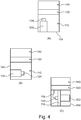
- Fig. 4 shows further exemplary embodiments in which the motor 122 and the pump 124 are arranged at different positions in the tank area 110.
- the tank area 110 has a housing 150 in which the exemplary tank is accommodated (not shown in the figure).
- the motor 122 is attached to the housing 150 and the pump 124 can be held by the motor 122 accordingly.
- a line is formed between the pump 124 and the hydraulic circuit board 130, which is in the Figure 4A cannot be seen.
- the Figure 4B shows a further possibility of fastening the motor 122 and the pump 124 on a side wall of the housing 150 and not on a wall of the housing 150 opposite the hydraulic circuit board 130 (as in FIG Figure 4A ).
- FIG. 12 shows an embodiment in which the holder structure 115 of the tank area 110 does not provide a hydraulic channel or flow path in order to pump the hydraulic fluid pumped by the pump 124 to the hydraulic circuit board 130.
- a liquid line 118 is formed as a connection between the pump 124 and the hydraulic circuit board 130.
- Hydraulic line 118 can also be used in the same manner in FIGS 4A and 4B be trained, even if it is not visible there.
- the motor 122 and / or the pump 124 can be arranged in the tank or next to it.
- the tank region 110 may have a cavity between the housing 150 and the liquid tank that can accommodate the motor 122 and the pump 124.
- the Fig. 5 shows further exemplary embodiments in which at least the motor 122 is arranged outside the housing 150 of the tank area 110.
- the motor 122 is attached to an outer surface of the housing 150.
- a corresponding fastening option can be formed on the housing 150 of the tank area 110.
- Motor 122 again couples to pump 124, which in this exemplary embodiment is inside housing 150 is formed and can be located, for example, in the tank itself or in a corresponding cavity in the tank area 110.
- the Figure 5B shows an embodiment in which the motor 122 together with the pump 124 is arranged next to the tank area 110, ie outside the housing 150 on the hydraulic circuit board 130.
- a space 119 may be formed between the motor 122 and the housing 150.
- the Figure 5C shows an embodiment in which the housing 150 of the tank area 110 has a recess which can accommodate the motor 122.
- the motor 122 again couples directly or via a coupling to the pump 124, which in this exemplary embodiment is fastened within the housing 150, that is to say to a bottom of the recess.
- the cutout can be chosen to be large enough to accommodate the motor 122 completely or at least partially, so that it does not mount laterally or at the bottom when it is installed in the rail vehicle (as is the case in FIG Figure 5A can be seen) protrudes.
- the motor may also be attached to the housing 150 on a side wall of the housing (i.e., not opposite the hydraulic circuit board 130).
- Exemplary embodiments of the present invention likewise relate to a hydraulic device which does not have a motor 122, but merely provides a fastening possibility in order to fasten the motor 122 to an outer housing of the tank area 110, for example.
Landscapes
- Engineering & Computer Science (AREA)
- Mechanical Engineering (AREA)
- General Engineering & Computer Science (AREA)
- Physics & Mathematics (AREA)
- Fluid Mechanics (AREA)
- Supply Devices, Intensifiers, Converters, And Telemotors (AREA)
- Details Of Reciprocating Pumps (AREA)
Description
- Die vorliegende Erfindung bezieht sich auf ein Hydrogerät für ein Schienenfahrzeug und insbesondere auf eine optimierte Anordnung einer Motor-Pumpeneinheit in Hydrogeräte für Schienenfahrzeuge.
- Ein Hydrogerät ist eine hydraulische Steuerungs- und Versorgungseinheit, die einen gesteuerten oder geregelten hydraulischen Fluss für verschiedene Komponenten des entsprechenden Schienenfahrzeuges bereitstellt. Beispielsweise können in den Hydrogeräten steuerbare Ventile ausgebildet sein, die gezielt bestimmte hydraulische Leitungen aktivieren, um dort einen Volumenstrom zu bewirken, oder auch deaktivieren, wobei die Steuerung der Hydrogeräte über eine Fahrzeugsteuereinheit geschehen kann. Hydrogeräte bestehen im Allgemeinen aus drei Hauptbestandteilen: ein Steuerbereich mit einem Steuerdeckel, eine Verschaltungsplatine (Steuerplatte) und ein Tankbereich mit einem Tank für eine hydraulische Flüssigkeit. Außerdem koppeln an die Steuerplatte meist ein Motor und eine Pumpe, um die hydraulische Flüssigkeit in die Steuerplatte zu pumpen.
- Hydrogeräte sind im Stand der Technik z.B. in
DE 196 12 582 A1 beschrieben. Das Dokument beschreibt eine Antriebseinheit für ein Fahrzeug, bei der eine Hydraulikpumpe und ein Elektromotor innerhalb eines Hydrauliktanks untergebracht sind. Dies ist u.a. vorteilhaft zur Schalldämpfung sowie zur gleichzeitigen Erzielung eines verbesserten Explosionsschutzes. - Die Druckschrift
US2011/0173966 A1 lehrt den Fachmann, einen Hydraulikschlauch derart in einem Hydrauliktank anzuordnen, dass auch bei verschiedenen Einbaulagen des Aggregats das Saugende des Schlauches stets mit Hydraulikflüssigkeit bedeckt ist, um einen problemlosen Betrieb zu gewährleisten. - Dokument
US2006 /0000757 A1 beschreibt die vorteilhafte Anordnung einer Hydraulikeinheit, bei der das Auswechseln des in die Hydraulikflüssigkeit eintauchenden Filters mit möglichst wenig Reinigungsaufwand verbunden ist. - Die Druckschrift
GB 1399071 - Die Druckschrift
EP 1 413 757 A2 beschreibt ein Motorpumpenaggregat, das die Merkmale entsprechend dem Oberbegriff von Patentanspruch 1 umfasst. - Bei Schienenfahrzeugen neuerer Bauart, wie beispielsweise Straßenbahnen, die in einer Niederflurausführung gefertigt werden, wird der zur Verfügung stehende Bauraum zunehmend eingeschränkt. Somit werden zunehmend erhöhte Anforderungen hinsichtlich der Größe der einzelnen Komponenten, die in dem Schienenfahrzeug unterzubringen sind, gestellt. Aus diesem Grund besteht eine Anforderung darin, die Baugröße der Komponenten wie beispielsweise des Hydrogeräts zu verringern, so dass sie platzsparender in dem sich verringernden Bauraum untergebracht werden können. Andererseits sollen häufig weitere oder zusätzliche Funktionen in dem gleichen bzw. in einem sich verringernden Bauraum untergebracht werden. Konventionelle Hydrogeräte erfüllen diese Erfordernisse zunehmend nicht mehr.
-
Fig. 6 zeigt ein erstes konventionelles Hydrogerät für Schienenfahrzeuge. Es besteht aus einem Steuerbereich 440, einer hydraulischen Verschaltungsplatine 430 und einem Tankbereich 410. In dem Tankbereich 410 ist eine Pumpe 124 und in dem Steuerbereich 440 ist ein Motor 122 angeordnet. Der Motor 122 ist über eine Durchführung 460 durch die hydraulische Verschaltungsplatine 430 mit der Pumpe 124 auf der gegenüberliegenden Seite der hydraulischen Verschaltungsplatine 430 verbunden. Beispielsweise können der Motor 122 und die Pumpe 124 eine gemeinsame Welle aufweisen, die direkt durch die Durchführung 460 gelegt ist. Alternativ ist möglich, dass die Motorwelle 122 mit einer entsprechenden Welle der Pumpe 124 über eine Kupplung (nicht gezeigt) in der Durchführung 460 miteinander gekoppelt ist. - Die Pumpe 124 saugt eine Flüssigkeit aus dem Tankbereich 410 an, und pumpt die hydraulische Flüssigkeit durch Verbindungskanäle (nicht in der
Fig. 6 gezeigt) in die hydraulische Verschaltungsplatine 430 . Auf der hydraulischen Verschaltungsplatine 430 können außerdem verschiedene elektrische oder hydraulische Komponenten ausgebildet sein, die über den Steuerbereich 440 (oder über den Tankbereich) elektrisch angesteuert oder elektrisch versorgt werden. -
Fig. 7 zeigt ein weiteres konventionelles Hydrogerät 500 mit einem Tankbereich 510, einer Steuereinheit 540 mit integrierter hydraulischer Verschaltungsplatine 530 und einer externen Motor-Pumpenkombination 122, 124, die über zumindest einen Fluidkanal 520 mit der hydraulischen Verschaltungsplatine 530 und mit dem Tankbereich 510 verbunden ist, um die hydraulische Flüssigkeit von dem Tankbereich 510 in die hydraulische Verschaltungsplatine 530 zu pumpen. Außerdem ist ein Motorflansch 525 vorgesehen, um die Motor-Pumpenkombination 122, 124 zu halten. - Die gezeigten Hydrogeräte weisen folgende Nachteile auf. Zum einen beansprucht die Motor-Pumpenkombination 122, 124 auf der Steuerplatte 430 sehr viel Platz. Dadurch können weniger Bauelemente auf der Steuerplatte 430 angeordnet werden. Außerdem erfordert die Durchführung 460 der Motor- und Pumpenwelle einen Durchbruch durch die Steuerplatte 430. Dieser Durchbruch vermindert den für die Verschaltung der Bauelemente nutzbaren Steuerplattenquerschnitt erheblich und führt zu aufwendigen Konstruktionen für die Verbindungsbohrungen zwischen der Steuerplatte 430 und den angebrachten Bauelementen (in den
Fig. 6 und7 nicht gezeigt). Bei dem speziellen Hydrogerät, wie es dieFig. 7 zeigt, ist zwar eine Trennung zwischen der Steuerplatte 530 von der Befestigung der Motor-Pumpenkombination 122, 124 vorgesehen, sie benötigen jedoch einen eigenen Motorflansch 525 und Verbindungselemente 520 zum Überleiten des Volumenstromes von dem Motorflansch 525 zur Steuerplatte 540, 530. - Daher besteht ein Bedarf nach Hydrogeräten für Schienenfahrzeuge, die es erlauben, entweder die Baugröße zu verringern oder aber zusätzliche Funktionen auf einem gleichen Bauraum unterzubringen.
- Die vorliegende Erfindung löst das obengenannte technische Problem durch ein Hydrogerät nach Anspruch 1. Die abhängigen Ansprüche beziehen sich auf weitere vorteilhafte Weiterbildungen.
- Die vorliegende Erfindung betrifft ein Hydrogerät für ein Schienenfahrzeug, wobei das Hydrogerät einen Tankbereich für eine hydraulische Flüssigkeit, einen Motor mit einer Pumpe zum Pumpen der hydraulischen Flüssigkeit, eine hydraulische Verschaltungsplatine zum Bereitstellen von hydraulischen Flüssigkeitspfaden und zum Aufnehmen von hydraulischen Bauelementen und einen Steuerbereich zum Ansteuern der hydraulischen Bauelemente aufweist. Der Tankbereich und der Steuerbereich sind auf gegenüberliegenden Seiten der hydraulischen Verschaltungsplatine angeordnet, und der Motor ist zusammen mit der Pumpe auf einer Seite der hydraulischen Verschaltungsplatine angeordnet. Das Hydrogerät ist dadurch gekennzeichnet, dass es weiter eine Haltestruktur zum Halten des Motors und der Pumpe umfasst und die Haltestruktur in dem Tankbereich gehalten wird und an die hydraulische Verschaltungsplatine koppelt, wobei der Motor und die Pumpe nicht direkt an die hydraulische Verschaltungsplatine koppeln, sondern durch die Haltestruktur unabhängig von der hydraulischen Verschaltungsplatine gehalten werden.
- Unter einem Flüssigkeitspfad sollen alle Hohlräume verstanden werden, durch die eine hydraulische Flüssigkeit geleitet werden kann. Die genannten hydraulischen Flüssigkeitspfade umfassen einerseits hydraulische Leitungen, die nach außen geführt werden, aber auch Flüssigkeitsverbindungen, die innerhalb der hydraulischen Verschaltungsplatine ausgebildet sind und beispielsweise eine Verbindung von der Pumpe zu einem beispielhaften Ventil bereitstellen. Außerdem braucht kein Gehäuse vorhanden sein. Falls doch, kann die hydraulische Verschaltungsplatine beispielsweise derart in dem Gehäuse angeordnet sein, dass sie das Gehäuse in zwei separate Bereiche trennt (den Tankbereich und den Steuerbereich).
- Die oben genannte technische Aufgabe wird durch die vorliegende Erfindung dadurch gelöst, dass eine hydraulische Steuerungs- und Versorgungseinheit (Hydrogerät) geschaffen wird, die im Vergleich zu den konventionellen Hydrogeräten eine identische Funktionalität aufweist, jedoch bei ihrer Umsetzung den notwendigen Einbauraum vermindert oder bei ihrer Umsetzung mehr Funktionen erlaubt, die in dem Einbauraum realisiert werden können.
- Bei weiteren Ausführungsbeispielen umfassen die hydraulischen Bauelemente zumindest ein Ventil und/oder zumindest einen Sensor, die elektrisch steuerbar sind. Der Steuerbereich kann als ein Deckel ausgebildet sein und eine Anschlusseinheit aufweisen. Der Steuerbereich kann außerdem eine elektrische Verschaltung umfassen, die die elektrisch steuerbaren hydraulischen Bauelemente mit der Anschlusseinheit verschalten, so dass die hydraulischen Bauelemente von außerhalb des Gehäuses steuerbar sind.
- Bei weiteren Ausführungsbeispielen ist die Pumpe zwischen dem Motor und der hydraulischen Verschaltungsplatine angeordnet. Optional kann der Motor auch zwischen der Pumpe und der hydraulischen Verschaltungsplatine angeordnet sein. Ein Vorteil der ersten Ausfertigung besteht darin, dass die hydraulische Flüssigkeit direkt von der Pumpe in die hydraulische Verschaltungsplatine gepumpt werden kann, ohne dass zusätzliche Flüssigkeitsleitungen erforderlich wären. Ein Vorteil der zweiten Ausfertigung besteht darin, dass der Motor einen sicheren Halt durch die hydraulische Verschaltungsplatine bekommt, so dass, insbesondere wenn der Motor größer ausgebildet ist als die Pumpe, eine mechanisch stabilere Konstruktion erreicht werden kann.
- Bei weiteren Ausführungsbeispielen umfasst die Pumpe und der Motor eine gemeinsame oder zwei miteinander gekoppelte Drehwelle(n), wobei die Drehwelle(n) von der hydraulischen Verschaltungsplatine beabstandet ist/sind. Dies bedeutet insbesondere, dass die Drehwelle der Pumpe und/oder die Drehwelle des Motors nicht an die hydraulische Verschaltungsplatine koppeln und somit auch nicht direkt Schwingungen auf die hydraulische Verschaltungsplatine übertragen können. Beispielsweise ist dazu ein Zwischenraum zwischen der oder den Drehwelle(n) ausgebildet, der die beispielhaften negativen Einflüsse von Schwingungen auf Sensoren oder ähnlichen Bauelementen unterdrückt.
- Bei weiteren Ausführungsbeispielen ist die Pumpe zusammen mit dem Motor in dem Tankbereich angeordnet. Ein Vorteil dieser Ausführungsform besteht darin, dass der Motor zusammen mit der Pumpe durch die in dem Tank bestehende Flüssigkeit gekühlt werden kann. Außerdem wird hierdurch eine sehr effiziente Volumenauslastung erreicht, da das Tankvolumen nur soweit vergrößert werden muss, wie das Volumen der Kombination von Pumpe und Motor zusammen umfasst.
- Bei weiteren Ausführungsbeispielen umfasst der Tankbereich einen Tank zur Aufbewahrung der Hydraulikflüssigkeit und die Pumpe ist zusammen mit dem Motor in dem Tank untergebracht.
- Bei weiteren Ausführungsbeispielen umfasst das Hydrogerät eine Haltestruktur zum Halten des Motors und/oder der Pumpe. Die Haltestruktur wird in dem Steuerbereich oder in dem Tankbereich gehalten und koppelt an die hydraulische Verschaltungsplatine. Ein Vorteil dieser Ausführungsform besteht darin, dass es möglich wird, die durch den Motor und/oder der Pumpe erzeugten Schwingungen zu dämpfen und nicht direkt auf die Verschaltungsplatine mit den darauf ausgebildeten hydraulischen Bauelementen zu übertragen. Außerdem können bereits vorhandene Strukturen als Haltestrukturen genutzt werden.
- Bei weiteren Ausführungsbeispielen ist die Haltestruktur Teil des Tankbereichs oder Teil des Steuerbereichs.
- Bei weiteren Ausführungsbeispielen koppelt die Haltestruktur an die hydraulische Verschaltungsplatine oder die Pumpe ist über eine Leitung mit der hydraulischen Verschaltungsplatine verbunden.
- Bei weiteren Ausführungsbeispielen umfasst der Tankbereich ein Tankgehäuse und der Steuerbereich umfasst einen Deckel, wobei die Haltestruktur an dem Tankgehäuse oder dem Deckel befestigt sein kann.
- Bei weiteren Ausführungsbeispielen ist die Pumpe in dem Tankbereich angeordnet und der Motor an einer Außenwand des Tankbereiches befestigt. Optional ist der Motor und die Pumpe auf der hydraulischen Schaltungsplatine neben dem Tankbereich angeordnet.
- Eine weitere Ausführungsform, die nicht Gegenstand der vorliegenden Erfindung ist, bezieht sich ebenfalls auf ein Hydrogerät für ein Schienenfahrzeug mit einem Tankbereich für eine hydraulische Flüssigkeit, einer hydraulischen Verschaltungsplatine zum Bereitstellen von hydraulischen Flüssigkeitspfaden und zum Aufnehmen von hydraulischen Bauelementen und einem Steuerbereich zum Ansteuern der hydraulischen Bauelemente, wobei der Tankbereich und der Steuerbereich auf gegenüberliegende Seiten der hydraulischen Verschaltungsplatine angeordnet sind. Außerdem umfasst dieses Hydrogerät eine Pumpe zum Pumpen der hydraulischen Flüssigkeit, die in dem Tankbereich angeordnet ist. Optional ist eine Befestigungsmöglichkeit am Tankbereich vorgesehen, um einen Motor zum Betreiben der Pumpe an einer äußeren Oberfläche des Tankbereiches zu befestigen.
- Die vorliegende Erfindung bezieht sich ebenfalls auf ein Schienenfahrzeug mit einem der zuvor beschriebenen Hydrogeräte.
- Die Ausführungsbeispiele der vorliegenden Erfindung werden besser verstanden von der folgenden detaillierten Beschreibung und den beiliegenden Zeichnungen der unterschiedlichen Ausführungsbeispiele, die jedoch nicht so verstanden werden sollten, dass sie die Offenbarung auf die spezifischen Ausführungsformen einschränkt, sondern lediglich der Erklärung und dem Verständnis dienen.
- Fig. 1
- zeigt ein Hydrogerät für ein Schienenfahrzeug nach einem Ausführungsbeispiel der vorliegenden Erfindung.
- Fig. 2
- zeigt weitere Ausführungsformen des Hydrogerätes.
- Fig. 3
- zeigt Ausführungsbeispiele für Hydrogeräte mit einer Haltestruktur.
- Fig. 4
- zeigt Ausführungsbeispiele, in denen der Motor und die Pumpe an verschiedenen Positionen im Tankbereich angeordnet sind.
- Fig. 5
- zeigt Ausführungsbeispiele, in denen der Motor außerhalb des Tankbereiches angeordnet ist.
- Fig. 6
- zeigt ein erstes Hydrogerät konventioneller Bauart.
- Fig. 7
- zeigt ein zweites Hydrogerät konventioneller Bauart.
-
Fig. 1 zeigt ein Hydrogerät für ein Schienenfahrzeug, wobei das Hydrogerät die folgenden Komponenten umfasst: einen Tankbereich 110 für eine hydraulische Flüssigkeit (nicht gezeigt), einen Motor 122 mit einer Pumpe 124 zum Pumpen der hydraulischen Flüssigkeit, eine hydraulische Verschaltungsplatine 130 zum Bereitstellen von hydraulischen Flüssigkeitspfaden 132, 133 und zum Aufnehmen von hydraulischen Bauelementen 134, einen Steuerbereich 140 zum Ansteuern der hydraulischen Bauelemente 134 und ein Gehäuse 150. In dem Gehäuse 150 sind der Tankbereich 110, die hydraulische Verschaltungsplatine 130 und der Steuerbereich 140 untergebracht, wobei der Tankbereich 110 und der Steuerbereich 140 auf gegenüberliegenden Seiten und der Motor 122 zusammen mit der Pumpe 124 auf einer Seite der hydraulischen Verschaltungsplatine 130 angeordnet ist. - Auf der linken Seite der
Fig. 1 ist der Motor 122 zusammen mit der Pumpe 124 im Tankbereich 110 angeordnet, während auf der rechten Seite der Motor 122 mit der Pumpe 124 in dem Steuerbereich 140 angeordnet ist. - Die hydraulischen Bauelemente 134 können beispielsweise Ventile und/oder Sensoren umfassen, die hydraulischen Flusspfade 132, 133 öffnen oder schließen oder Messungen an der hydraulischen Flüssigkeit vornehmen (beispielsweise Druckmessungen). Bei den hydraulischen Flusspfaden 132, 133 kann es sich um interne Flusspfade 132 zwischen den Komponenten auf der hydraulischen Verschaltungsplatine 130 handeln oder aber um weitere hydraulische Flusspfade 133, die an eine externe hydraulische Leitung (außerhalb des Gehäuses) koppeln. Die Ventile können beispielsweise elektromagnetisch gesteuerte Ventile sein, die über eine elektrische Leitung 142 mit einer Anschlusseinheit 144 verbunden sind, wobei die Anschlusseinheit 144 eine Verbindung zwischen dem Innenbereich des Gehäuses 150 und dem Außenbereich herstellt. Beispielsweise kann das Hydrogerät durch eine Steuereinheit des Schienenfahrzeuges über die Anschlusseinheit 144 elektrisch gesteuert werden, um beispielsweise Sensordaten von den Sensoren auszulesen oder die Ventile über entsprechende Signale zu steuern.
- Die hydraulische Verschaltungsplatine 130 unterteilt beispielsweise den Innenbereich des Gehäuses 150 in zwei Abschnitte. In dem einen Abschnitt ist der Tankbereich 110, der insbesondere den Tank selbst umfasst, untergebracht, während in dem anderen Bereich der Steuerbereich 140 ausgebildet ist. Der Motor 122 zusammen mit der Pumpe 124 können beispielsweise direkt in dem Tank angeordnet werden (siehe linke Seite der
Fig. 1 ), so dass sie von der hydraulischen Flüssigkeit umströmt werden kann. Dies bietet den Vorteil, dass die hydraulische Flüssigkeit gleichzeitig eine Kühlung für den Motor 122 als auch für die Pumpe 124 bereitstellt. Die Unterbringung des Motors 122 und der Pumpe 124 in dem Tankbereich 110 bietet darüber hinaus den Vorteil, dass in dem Steuerbereich 140 mehr Platz zur Verfügung steht für zusätzliche oder weitere hydraulische oder nichthydraulische Bauelemente. Der Steuerbereich 140 kann aber auch entsprechend kleiner gewählt werden. Der zusätzliche Platzbedarf im Tankbereich 110, der durch das Einbringen des Motors 122 und der Pumpe 124 zusätzlich zur Verfügung stehen muss, beschränkt sich dabei lediglich auf das Volumen des Motors 122 und des Volumens der Pumpe 124 selbst, so dass ein zusätzlicher Mehrbedarf an Raum auf ein Minimum beschränkt wird. Durch die Verlagerung des Motors in den Tankbereich kann außerdem die Höhe des Steuerdeckels verringert werden. Der Tankdeckel kann um dieses Maß vergrößert werden. Somit verändert sich die Gesamthöhe des Gerätes nicht und das verfügbare Ölvolumen im Tank kann nahezu konstant gehalten werden. -
Fig. 2 zeigt Ausführungsbeispiele, in welchen der Motor 122 und die Pumpe 124 in dem Tankbereich 110 untergebracht sind. Hierbei gibt es zwei Möglichkeiten: die Pumpe 124 wird zwischen dem Motor 122 und der hydraulischen Verschaltungsplatine 130 angeordnet (siehe linke Seite auf derFig. 2 ) oder aber der Motor 122 wird zwischen der Pumpe 124 und der hydraulischen Verschaltungsplatine 130 angeordnet (siehe rechte Seite derFig. 2 ). - Das Ausführungsbeispiel auf der linken Seite der
Fig. 2 , wo die Pumpe 124 direkt an die hydraulische Verschaltungsplatine 130 gekoppelt ist, bietet den Vorteil, dass die hydraulischen Flusspfade, die in der hydraulischen Verschaltungsplatine 130 ausgebildet sind, direkt durch die Pumpe 124 mit der hydraulischen Flüssigkeit versorgt werden können. - Bei dem Ausführungsbeispiel auf der rechten Seite der
Fig. 2 ist eine zusätzliche hydraulische Flussleitung von der Pumpe 124 hin zu der hydraulischen Verschaltungsplatine 130 ausgebildet, die jedoch in derFig. 2 auf der rechten Seite nicht gezeigt ist. Diese Ausführung bietet jedoch den Vorteil, dass der Motor 122 direkt auf der hydraulischen Verschaltungsplatine 130 befestigt ist und somit einen besseren Halt aufweist. - In beiden Ausführungsformen wird die Welle, die durch den Motor 122 und die Pumpe 124 verläuft, nicht in die hydraulische Verschaltungsplatine 130 hineingeführt. Insbesondere kann ein Zwischenraum zwischen der Welle und der hydraulischen Verschaltungsplatine 130 vorhanden sein. Daher bieten Ausführungsbeispiele weiter den Vorteil, dass keine zusätzlichen Löcher oder Bohrungen in der hydraulischen Verschaltungsplatine 130 ausgebildet werden müssen, so dass das gesamte Volumen der hydraulischen Verschaltungsplatine 130 für das Bereitstellen von hydraulischen Flusspfaden zur Verfügung steht.
-
Fig. 3 zeigt weitere Ausführungsbeispiele, bei welchen der Motor 122 und die Pumpe 124 nicht direkt an die hydraulische Verschaltungsplatine 130 koppeln, sondern durch eine Haltestruktur 115, 145 gehalten werden. Die Haltestruktur 115, 145 kann beispielsweise eine Haltestruktur 115 des Tankbereichs 110 oder eine Haltestruktur 145 des Steuerbereichs 140 sein. Auf der linken Seite derFig. 3 ist das Ausführungsbeispiel gezeigt, wo die Haltestruktur 115 Teil des Tankbereichs 110 ist, so dass die Haltestruktur 110 den Motor 122 und die Pumpe 124 in dem Tankbereich 110 hält. Optional kann die Haltestruktur 115 ebenfalls eine Verbindung 116 zu der hydraulischen Schaltungsplatine 130 bereitstellen, um die hydraulische Flüssigkeit von der Pumpe 124 hin zu der hydraulischen Verschaltungsplatine 130 zu leiten. Außerdem kann auch eine andere Lösung außerhalb der Haltestruktur für hydraulische Verbindungen genutzt werden (z.B. eine Rohr- oder Schlauchverbindung wie sie in derFig. 4C gezeigt ist). - In dem Ausführungsbeispiel auf der rechten Seite der
Fig. 3 , ist die Haltestruktur 145 Teil des Steuerbereichs 140 und wird beispielsweise durch einen Steuerdeckel gehalten. In diesem Ausführungsbeispiel ist ein zusätzlicher hydraulischer Flusspfad 146 von der Pumpe 124 hin zu der hydraulischen Verschaltungsplatine 130 ausgebildet. Es können aber auch zusätzliche Rohr- oder Schlauchverbindungen ausgebildet werden, um den hydraulischen Flusspfad herzustellen. Ferner ist eine Verbindung zum Tank ausgebildet, die in derFig. 3 nicht gezeigt ist. -
Fig. 4 zeigt weitere Ausführungsbeispiele, in denen der Motor 122 und die Pumpe 124 an verschiedenen Positionen im Tankbereich 110 angeordnet sind. - In der
Fig. 4A weist der Tankbereich 110 ein Gehäuse 150 auf, in welchem der beispielhafte Tank untergebracht ist (nicht gezeigt in der Figur). In diesem Ausführungsbeispiel ist der Motor 122 an dem Gehäuse 150 befestigt und die Pumpe 124 kann entsprechend durch den Motor 122 gehalten werden. Zwischen der Pumpe 124 und der hydraulischen Verschaltungsplatine 130 ist beispielsweise eine Leitung ausgebildet, die in derFig. 4A nicht zu sehen ist. - Die
Fig. 4B zeigt eine weitere Möglichkeit, den Motor 122 und die Pumpe 124 an einer seitlichen Wand des Gehäuses 150 zu befestigen und nicht an einer der hydraulischen Verschaltungsplatine 130 gegenüberliegenden Wand des Gehäuses 150 anzubringen (wie in derFig. 4A ). - Die
Fig. 4C zeigt ein Ausführungsbeispiel, in welchem die Halterstruktur 115 des Tankbereiches 110 keinen hydraulischen Kanal oder Flusspfad bereitstellt, um die durch die Pumpe 124 gepumpte hydraulische Flüssigkeit zu der hydraulischen Verschaltungsplatine 130 zu pumpen. Stattdessen ist in diesem Ausführungsbeispiel eine Flüssigkeitsleitung 118 als Verbindung zwischen der Pumpe 124 und der hydraulischen Verschaltungsplatine 130 ausgebildet. Die hydraulische Leitung 118 kann in der gleichen Weise ebenfalls in denFig. 4A und 4B ausgebildet sein, auch wenn sie dort nicht zu sehen ist. Bei allen drei Ausführungsbeispielen derFig. 4 kann der Motor 122 und/oder die Pumpe 124 in dem Tank angeordnet sein oder auch daneben. Beispielsweise kann der Tankbereich 110 zwischen dem Gehäuse 150 und dem Flüssigkeitstank einen Hohlraum aufweisen, der den Motor 122 und die Pumpe 124 aufnehmen kann. - Die
Fig. 5 zeigt weitere Ausführungsbeispiele, in denen zumindest der Motor 122 außerhalb des Gehäuses 150 des Tankbereiches 110 angeordnet ist. - In der
Fig. 5A ist der Motor 122 an einer Außenfläche des Gehäuses 150 befestigt. Dazu kann beispielsweise eine entsprechende Befestigungsmöglichkeit an dem Gehäuse 150 des Tankbereiches 110 ausgebildet sein. Der Motor 122 koppelt wieder an die Pumpe 124, die in diesem Ausführungsbeispiel innerhalb des Gehäuses 150 ausgebildet ist und sich beispielsweise in dem Tank selbst oder in einem entsprechenden Hohlraum des Tankbereiches 110 befinden kann. - Die
Fig. 5B zeigt ein Ausführungsbeispiel, bei welchem der Motor 122 zusammen mit der Pumpe 124 neben dem Tankbereich 110, d.h. außerhalb des Gehäuses 150 auf der hydraulischen Verschaltungsplatine 130 angeordnet ist. Beispielsweise kann zwischen dem Motor 122und dem Gehäuse 150 ein Zwischenraum 119 ausgebildet sein. - Die
Fig. 5C zeigt ein Ausführungsbeispiel, in welchem das Gehäuse 150 des Tankbereiches 110 eine Aussparung aufweist, die den Motor 122 aufnehmen kann. Der Motor 122 koppelt wieder direkt oder über eine Kupplung an die Pumpe 124, die in diesem Ausführungsbeispiel innerhalb des Gehäuses 150, d.h. an einem Boden der Aussparung befestigt ist. Die Aussparung kann beispielsweise so groß gewählt werden, dass sie den Motor 122 vollständig oder zumindest teilweise aufnimmt, so dass er beim Einbau in dem Schienenfahrzeug nicht seitlich oder unten (wie es beispielsweise in derFig. 5A zu sehen ist) herausragt. - Bei weiteren Ausführungsbeispielen kann der Motor ebenfalls an einer Seitenwand des Gehäuses (d.h. nicht gegenüberliegend der hydraulischen Verschaltungsplatine 130) an dem Gehäuse 150 befestigt sein.
- Ausführungsbeispiele der vorliegenden Erfindung beziehen sich ebenfalls auf ein Hydrogerät, welches keinen Motor 122 aufweist, sondern lediglich eine Befestigungsmöglichkeit bereitstellt, um den Motor 122 beispielsweise an einem Außengehäuse des Tankbereiches 110 zu befestigen.
- Ausführungsbeispiele der vorliegenden Erfindung weisen die folgenden Vorteile auf:
- (a) Der Motor 122 und die Pumpe 124 werden derart verbunden und auf einer Seite der hydraulischen Schaltungsplatine 130 angeordnet, dass ein Durchbruch durch die hydraulische Schaltungsplatine 130 (oder eine Änderung) nicht erforderlich ist.
- (b) Der Motor 122 und die Pumpe 124 werden durch eine Haltestruktur 115, 145 als Teil des Steuerbereichs 140 oder des Tankbereichs 110 unabhängig von der hydraulischen Schaltungsplatine 130 gehalten, so dass keine separate Halterung an der hydraulischen Verschaltungsplatine 130 wie beispielsweise ein Motorflansch erforderlich ist. :
- (c) Die vorliegende Erfindung bietet außerdem die Möglichkeit, den Motor 122 zusammen mit der Pumpe 124 im Ölvolumen des Tanks 110 als auch außerhalb des Ölvolumens anzuordnen (aber noch im Tankbereich).
- Die in der Beschreibung, den Ansprüchen und den Figuren offenbarten Merkmale der Erfindung können sowohl einzeln als auch in beliebiger Kombination für die Verwirklichung der Erfindung wesentlich sein.
-
- 110
- Tankbereich
- 115,145
- Haltestruktur
- 122
- Motor
- 124
- Pumpe
- 130
- hydraulische Verschaltungsplatine
- 132,133
- Flüssigkeitspfade
- 134
- hydraulische Bauelemente
- 140
- Steuerbereich
- 144
- Anschlusseinheit
- 150
- Gehäuse
- 410,510
- Tankbereich konventioneller Bauart
- 440, 540
- Steuerbereich konventioneller Bauart
- 430,530
- hydraulische Verschaltungsplatine konventioneller Bauart
- 520
- Verbindungselement
- 525
- Motorflansch
Claims (10)
- Hydrogerät für ein Schienenfahrzeug mit einem Tankbereich (110) für eine hydraulische Flüssigkeit, einem Motor (122) mit einer Pumpe (124) zum Pumpen der hydraulischen Flüssigkeit, einer hydraulischen Verschaltungsplatine (130) zum Bereitstellen von hydraulischen Flüssigkeitspfaden (132) und zum Aufnehmen von hydraulischen Bauelementen (134) und einem Steuerbereich (140) zum Ansteuern der hydraulischen Bauelemente (134), wobei- der Tankbereich (110) und der Steuerbereich (140) auf gegenüberliegenden Seiten der hydraulischen Verschaltungsplatine (130) angeordnet sind, und- der Motor (122) zusammen mit der Pumpe (124) auf einer Seite der hydraulischen Verschaltungsplatine (130) angeordnet ist,
dadurch gekennzeichnet, dass- das Hydrogerät weiter eine Haltestruktur (115, 145) zum Halten des Motors (122) und der Pumpe (124) umfasst und die Haltestruktur (115, 145) in dem Tankbereich (110) gehalten wird und an die hydraulische Verschaltungsplatine (130) koppelt,- wobei der Motor (122) und die Pumpe (124) nicht direkt an die hydraulische Verschaltungsplatine (130) koppeln, sondern durch die Haltestruktur (115, 145) unabhängig von der hydraulischen Verschaltungsplatine (130) gehalten werden. - Hydrogerät nach Anspruch 1,
dadurch gekennzeichnet, dass
die hydraulischen Bauelemente (134) zumindest ein Ventil und/oder zumindest einen Sensor umfassen, die elektrisch steuerbar sind, der Steuerbereich (140) eine Anschlusseinheit (144) und eine elektrische Verschaltung umfasst, die elektrohydraulische Bauelemente (134) mit der Anschlusseinheit (144) verschaltet, so dass die elektro-hydraulischen Bauelemente (134) von außerhalb des Gehäuses (150) ansteuerbar sind. - Hydrogerät nach Anspruch 1 oder Anspruch 2,
dadurch gekennzeichnet, dass
die Pumpe (124) zwischen dem Motor (122) und der hydraulischen Verschaltungsplatine (130) angeordnet ist, oder der Motor (122) zwischen der Pumpe (124) und der hydraulischen Verschaltungsplatine (130) angeordnet ist. - Hydrogerät nach einem der vorhergehenden Ansprüche, wobei die Pumpe (124) und der Motor (122) eine gemeinsame oder zwei miteinander gekoppelte Welle(n) umfasst/umfassen,
dadurch gekennzeichnet, dass
die Drehwelle(n) von der hydraulischen Verschaltungsplatine (130) beabstandet ist/sind. - Hydrogerät nach einem der vorhergehenden Ansprüche,
dadurch gekennzeichnet, dass
die Pumpe (124) zusammen mit dem Motor (122) in dem Tankbereich (110) angeordnet ist. - Hydrogerät nach Anspruch 5,
dadurch gekennzeichnet, dass
der Tankbereich (110) einen Tank zur Aufbewahrung der Hydraulikflüssigkeit umfasst und die Pumpe (124) zusammen mit dem Motor (122) in dem Tank untergebracht ist. - Hydrogerät nach einem der vorhergehenden Ansprüche,
dadurch gekennzeichnet, dass
die Pumpe (124) über eine Leitung mit der hydraulischen Verschaltungsplatine (130) verbunden ist. - Hydrogerät nach Anspruch 7, dadurch gekennzeichnet, dass
der Tankbereich (110) ein Tankgehäuse umfasst und der Steuerbereich (140) einen Deckel umfasst und die Haltestruktur (115, 145) an dem Tankgehäuse oder dem Deckel befestigt ist. - Hydrogerät nach einem der vorhergehenden Ansprüche, dadurch gekennzeichnet, dass
die Pumpe (124) in dem Tankbereich (110) angeordnet ist und der Motor (122) an einer Außenwand (150) des Tankbereiches (110) befestigt ist. - Schienenfahrzeug mit einem Hydrogerät nach einem der vorhergehenden Ansprüche.
Priority Applications (1)
| Application Number | Priority Date | Filing Date | Title |
|---|---|---|---|
| PL16791390T PL3371451T3 (pl) | 2015-11-06 | 2016-11-04 | Agregat hydrauliczny |
Applications Claiming Priority (2)
| Application Number | Priority Date | Filing Date | Title |
|---|---|---|---|
| DE102015119055.9A DE102015119055B4 (de) | 2015-11-06 | 2015-11-06 | Hydrogerät |
| PCT/EP2016/076706 WO2017077060A1 (de) | 2015-11-06 | 2016-11-04 | Hydrogerät |
Publications (2)
| Publication Number | Publication Date |
|---|---|
| EP3371451A1 EP3371451A1 (de) | 2018-09-12 |
| EP3371451B1 true EP3371451B1 (de) | 2020-05-20 |
Family
ID=57241088
Family Applications (1)
| Application Number | Title | Priority Date | Filing Date |
|---|---|---|---|
| EP16791390.4A Active EP3371451B1 (de) | 2015-11-06 | 2016-11-04 | Hydrogerät |
Country Status (6)
| Country | Link |
|---|---|
| US (1) | US11085428B2 (de) |
| EP (1) | EP3371451B1 (de) |
| CN (1) | CN108431412B (de) |
| DE (1) | DE102015119055B4 (de) |
| PL (1) | PL3371451T3 (de) |
| WO (1) | WO2017077060A1 (de) |
Families Citing this family (7)
| Publication number | Priority date | Publication date | Assignee | Title |
|---|---|---|---|---|
| DE102018126114A1 (de) * | 2018-10-19 | 2020-04-23 | Robert Bosch Gmbh | Hydraulikaggregat |
| DE102019112677A1 (de) * | 2019-05-15 | 2020-11-19 | Knorr-Bremse Systeme für Schienenfahrzeuge GmbH | Hydraulikversorgungssystem für ein Fahrzeug |
| CN115053074A (zh) * | 2019-12-14 | 2022-09-13 | Kti液压系统公司 | 具有潜水电机的液压动力单元 |
| GB2604609B (en) * | 2021-03-08 | 2025-04-09 | Bamford Excavators Ltd | Hydraulic pump system |
| GB2604608B (en) | 2021-03-08 | 2025-04-23 | Bamford Excavators Ltd | Hydraulic system |
| US12305670B2 (en) | 2021-08-03 | 2025-05-20 | Kti Hydraulics Inc. | Submersible hydraulic power units with interchangeable manifolds |
| JP2025154225A (ja) * | 2024-03-29 | 2025-10-10 | 株式会社竹内製作所 | 作業用車両 |
Citations (1)
| Publication number | Priority date | Publication date | Assignee | Title |
|---|---|---|---|---|
| EP1413757A2 (de) * | 2002-10-24 | 2004-04-28 | Voith Turbo GmbH & Co. KG | Motorpumpenaggregat |
Family Cites Families (26)
| Publication number | Priority date | Publication date | Assignee | Title |
|---|---|---|---|---|
| US1780338A (en) * | 1928-12-31 | 1930-11-04 | Glacier Inc | Combination motor and pump |
| DE2201078A1 (de) | 1972-01-11 | 1973-07-19 | Karl Hehl | Maschinenfuss einer spritzgiessmaschine |
| DE2748897A1 (de) | 1977-11-02 | 1979-05-03 | Suspa Federungstech | Elektromotorisches pumpenaggregat |
| DE2938276A1 (de) * | 1979-09-21 | 1981-04-09 | Robert Bosch Gmbh, 7000 Stuttgart | Fluegelzellenverdichter |
| US4325678A (en) * | 1979-12-12 | 1982-04-20 | Hitachi, Ltd. | Hydraulic pressure producing system for a hydraulic press |
| DE4106060C2 (de) * | 1991-02-27 | 1995-11-30 | Fresenius Ag | Pumpe, insbesondere gekapselte medizinische Pumpe |
| US5330104A (en) * | 1992-07-02 | 1994-07-19 | Marcus David G | Portable outdoor mister |
| DE29601764U1 (de) | 1996-02-02 | 1996-03-28 | Schwarz, Wolfgang, 63303 Dreieich | Dreiecks-Faltkombination für den Golf-Rückschwung |
| DE19612582A1 (de) * | 1996-03-29 | 1997-10-02 | Miag Fahrzeugbau Gmbh | Antriebseinheit für ein Fahrzeug |
| US6596174B1 (en) * | 1998-09-11 | 2003-07-22 | Alexander C. Marcus | Diesel fuel cleaning and re-circulation system |
| DE10056929A1 (de) | 2000-11-17 | 2002-05-29 | Knorr Bremse Systeme | Hydropneumatische Federungeinheit sowie hydropneumatisches Federungssystem |
| DE10131750A1 (de) * | 2001-07-03 | 2003-01-16 | Bosch Rexroth Ag | Hydraulikaggregat |
| US6615866B2 (en) * | 2001-09-13 | 2003-09-09 | Morrell Incorporated | Hydraulic power assembly having a removable top |
| DE102004040909B4 (de) * | 2004-06-17 | 2007-07-05 | Hydac Filtertechnik Gmbh | Baueinheit |
| DE102004032256B3 (de) * | 2004-07-03 | 2005-12-15 | Jungheinrich Ag | Hydraulikaggregat für Flurförderzeuge |
| US7179390B1 (en) * | 2005-01-18 | 2007-02-20 | George F Layton | Method of filtering a fluid and remote filtering station |
| JP4820552B2 (ja) * | 2005-01-19 | 2011-11-24 | カヤバ工業株式会社 | 油圧制御装置、及びその油圧制御装置を備える油圧駆動ユニット |
| DE102008030715A1 (de) | 2008-06-27 | 2009-12-31 | Hydac Fluidtechnik Gmbh | Hydraulikaggregat |
| US8438845B2 (en) * | 2008-08-26 | 2013-05-14 | Limo-Reid, Inc. | Hoseless hydraulic system |
| CN202971420U (zh) | 2012-11-30 | 2013-06-05 | 油圣液压科技有限公司 | 液压节能装置 |
| JP5956948B2 (ja) | 2013-03-21 | 2016-07-27 | 日立オートモティブシステムズ株式会社 | 電子制御装置 |
| DE102013220451A1 (de) * | 2013-10-10 | 2015-04-16 | Continental Automotive Gmbh | Pumpe |
| US10087938B2 (en) * | 2013-10-18 | 2018-10-02 | Regal Beloit America, Inc. | Pump, associated electric machine and associated method |
| US9932981B2 (en) * | 2014-03-03 | 2018-04-03 | Preferred Utilities Manufacturing Corporation | Waterproof pump enclosure and system including same |
| CN204003691U (zh) | 2014-08-28 | 2014-12-10 | 卡特彼勒(青州)有限公司 | 液压系统和包括该液压系统的机器 |
| DE102015015863A1 (de) * | 2015-12-09 | 2017-06-14 | Fte Automotive Gmbh | Elektromotorisch angetriebene Flüssigkeitspumpe |
-
2015
- 2015-11-06 DE DE102015119055.9A patent/DE102015119055B4/de not_active Expired - Fee Related
-
2016
- 2016-11-04 US US15/773,906 patent/US11085428B2/en active Active
- 2016-11-04 WO PCT/EP2016/076706 patent/WO2017077060A1/de not_active Ceased
- 2016-11-04 CN CN201680077979.XA patent/CN108431412B/zh active Active
- 2016-11-04 EP EP16791390.4A patent/EP3371451B1/de active Active
- 2016-11-04 PL PL16791390T patent/PL3371451T3/pl unknown
Patent Citations (1)
| Publication number | Priority date | Publication date | Assignee | Title |
|---|---|---|---|---|
| EP1413757A2 (de) * | 2002-10-24 | 2004-04-28 | Voith Turbo GmbH & Co. KG | Motorpumpenaggregat |
Also Published As
| Publication number | Publication date |
|---|---|
| PL3371451T3 (pl) | 2020-11-16 |
| CN108431412A (zh) | 2018-08-21 |
| CN108431412B (zh) | 2021-01-01 |
| WO2017077060A1 (de) | 2017-05-11 |
| DE102015119055A1 (de) | 2017-05-11 |
| DE102015119055B4 (de) | 2019-05-09 |
| US11085428B2 (en) | 2021-08-10 |
| EP3371451A1 (de) | 2018-09-12 |
| US20180320674A1 (en) | 2018-11-08 |
Similar Documents
| Publication | Publication Date | Title |
|---|---|---|
| DE102015119055B4 (de) | Hydrogerät | |
| DE102016124188B4 (de) | Kontinuierlich-Variable-Ventildauer-Vorrichtung und mit dieser ausgestatteter Verbrennungsmotor | |
| DE19918575B9 (de) | Hydraulischer Aktuator für ein Antiblockierbremssystem | |
| DE102017208390A1 (de) | Hydraulikaggregat einer Schlupfregelung einer Fahrzeugbremsanlage mit einem Hydraulikblock und einem Motorblock | |
| EP1118800B1 (de) | Steuereinrichtung für ein Getriebe | |
| WO2009150013A1 (de) | Mehrwegeventil eines brennstoffsystems einer gasturbine | |
| DE102017106198A1 (de) | Betätigungsmodul für Kupplungen und Gangstellersysteme und Getriebe mit Betätigungsmodul | |
| DE102020203459A1 (de) | Getriebeölfiltermodul | |
| DE112019004003T5 (de) | Ventilblock für ein hydraulisches Bremssystem | |
| DE102006005553B4 (de) | Doppel-Getriebefilterkonstruktion | |
| WO2017005338A1 (de) | Hydraulikaggregat | |
| DE102004046448B4 (de) | Aktuator zum Steuern eines Bremshydraulikdrucks sowie Vorrichtung und Verfahren zum Überprüfen des selbigen | |
| EP3969753B1 (de) | Hydraulikversorgungssystem für ein fahrzeug | |
| WO2023061644A1 (de) | Kühlmitteltank, kühlmittelführungssystem und kraftfahrzeug | |
| DE102004042759A1 (de) | Geräte zum Steuern des Bremsfluiddrucks | |
| EP3762607B1 (de) | Pumpenvorrichtung für ein systemgehäuse eines fahrzeugs | |
| DE102005010297A1 (de) | Elektrohydraulisches Aggregat, insbesondere zur Wankstabilisierung eines Kraftfahrzeuges | |
| DE102006048399B4 (de) | Vorrichtung zur Entriegelung eines Bauteils eines Flugzeuges | |
| DE112019002539T5 (de) | Bremsflüssigkeitsdruck-Steuereinrichtung | |
| EP3959110B1 (de) | Hydraulikaggregat, insbesondere zur steuerung des bremsdrucks einer radbremse einer elektronisch schlupfregelbaren bremsanlage eines kraftfahrzeugs | |
| EP1886028A1 (de) | Betätigungsaggregat | |
| DE102008058926A1 (de) | Elektromotorische Antriebseinheit für Stellantriebe in Kraftfahrzeug | |
| EP0832809B1 (de) | Verfahren zur Entlüftung eines hydraulischen Servolenksystems | |
| DE102023205960A1 (de) | Kompressorgehäuse, integriertes System, integrierte Wärmepumpe, Fahrzeug und Herstellungsverfahren für Kompressorgehäuse | |
| DE102024104125A1 (de) | System zur Bereitstellung einer Betriebsflüssigkeit in einem Kraftfahrzeug |
Legal Events
| Date | Code | Title | Description |
|---|---|---|---|
| STAA | Information on the status of an ep patent application or granted ep patent |
Free format text: STATUS: UNKNOWN |
|
| STAA | Information on the status of an ep patent application or granted ep patent |
Free format text: STATUS: THE INTERNATIONAL PUBLICATION HAS BEEN MADE |
|
| PUAI | Public reference made under article 153(3) epc to a published international application that has entered the european phase |
Free format text: ORIGINAL CODE: 0009012 |
|
| STAA | Information on the status of an ep patent application or granted ep patent |
Free format text: STATUS: REQUEST FOR EXAMINATION WAS MADE |
|
| 17P | Request for examination filed |
Effective date: 20180606 |
|
| AK | Designated contracting states |
Kind code of ref document: A1 Designated state(s): AL AT BE BG CH CY CZ DE DK EE ES FI FR GB GR HR HU IE IS IT LI LT LU LV MC MK MT NL NO PL PT RO RS SE SI SK SM TR |
|
| AX | Request for extension of the european patent |
Extension state: BA ME |
|
| DAV | Request for validation of the european patent (deleted) | ||
| DAX | Request for extension of the european patent (deleted) | ||
| STAA | Information on the status of an ep patent application or granted ep patent |
Free format text: STATUS: EXAMINATION IS IN PROGRESS |
|
| 17Q | First examination report despatched |
Effective date: 20190614 |
|
| GRAP | Despatch of communication of intention to grant a patent |
Free format text: ORIGINAL CODE: EPIDOSNIGR1 |
|
| STAA | Information on the status of an ep patent application or granted ep patent |
Free format text: STATUS: GRANT OF PATENT IS INTENDED |
|
| INTG | Intention to grant announced |
Effective date: 20191218 |
|
| GRAS | Grant fee paid |
Free format text: ORIGINAL CODE: EPIDOSNIGR3 |
|
| GRAA | (expected) grant |
Free format text: ORIGINAL CODE: 0009210 |
|
| STAA | Information on the status of an ep patent application or granted ep patent |
Free format text: STATUS: THE PATENT HAS BEEN GRANTED |
|
| AK | Designated contracting states |
Kind code of ref document: B1 Designated state(s): AL AT BE BG CH CY CZ DE DK EE ES FI FR GB GR HR HU IE IS IT LI LT LU LV MC MK MT NL NO PL PT RO RS SE SI SK SM TR |
|
| REG | Reference to a national code |
Ref country code: GB Ref legal event code: FG4D Free format text: NOT ENGLISH |
|
| REG | Reference to a national code |
Ref country code: CH Ref legal event code: EP |
|
| REG | Reference to a national code |
Ref country code: DE Ref legal event code: R096 Ref document number: 502016010013 Country of ref document: DE |
|
| REG | Reference to a national code |
Ref country code: AT Ref legal event code: REF Ref document number: 1272764 Country of ref document: AT Kind code of ref document: T Effective date: 20200615 |
|
| REG | Reference to a national code |
Ref country code: LT Ref legal event code: MG4D |
|
| REG | Reference to a national code |
Ref country code: NL Ref legal event code: MP Effective date: 20200520 |
|
| PG25 | Lapsed in a contracting state [announced via postgrant information from national office to epo] |
Ref country code: NO Free format text: LAPSE BECAUSE OF FAILURE TO SUBMIT A TRANSLATION OF THE DESCRIPTION OR TO PAY THE FEE WITHIN THE PRESCRIBED TIME-LIMIT Effective date: 20200820 Ref country code: FI Free format text: LAPSE BECAUSE OF FAILURE TO SUBMIT A TRANSLATION OF THE DESCRIPTION OR TO PAY THE FEE WITHIN THE PRESCRIBED TIME-LIMIT Effective date: 20200520 Ref country code: GR Free format text: LAPSE BECAUSE OF FAILURE TO SUBMIT A TRANSLATION OF THE DESCRIPTION OR TO PAY THE FEE WITHIN THE PRESCRIBED TIME-LIMIT Effective date: 20200821 Ref country code: IS Free format text: LAPSE BECAUSE OF FAILURE TO SUBMIT A TRANSLATION OF THE DESCRIPTION OR TO PAY THE FEE WITHIN THE PRESCRIBED TIME-LIMIT Effective date: 20200920 Ref country code: LT Free format text: LAPSE BECAUSE OF FAILURE TO SUBMIT A TRANSLATION OF THE DESCRIPTION OR TO PAY THE FEE WITHIN THE PRESCRIBED TIME-LIMIT Effective date: 20200520 Ref country code: SE Free format text: LAPSE BECAUSE OF FAILURE TO SUBMIT A TRANSLATION OF THE DESCRIPTION OR TO PAY THE FEE WITHIN THE PRESCRIBED TIME-LIMIT Effective date: 20200520 Ref country code: PT Free format text: LAPSE BECAUSE OF FAILURE TO SUBMIT A TRANSLATION OF THE DESCRIPTION OR TO PAY THE FEE WITHIN THE PRESCRIBED TIME-LIMIT Effective date: 20200921 |
|
| PG25 | Lapsed in a contracting state [announced via postgrant information from national office to epo] |
Ref country code: LV Free format text: LAPSE BECAUSE OF FAILURE TO SUBMIT A TRANSLATION OF THE DESCRIPTION OR TO PAY THE FEE WITHIN THE PRESCRIBED TIME-LIMIT Effective date: 20200520 Ref country code: HR Free format text: LAPSE BECAUSE OF FAILURE TO SUBMIT A TRANSLATION OF THE DESCRIPTION OR TO PAY THE FEE WITHIN THE PRESCRIBED TIME-LIMIT Effective date: 20200520 Ref country code: RS Free format text: LAPSE BECAUSE OF FAILURE TO SUBMIT A TRANSLATION OF THE DESCRIPTION OR TO PAY THE FEE WITHIN THE PRESCRIBED TIME-LIMIT Effective date: 20200520 Ref country code: BG Free format text: LAPSE BECAUSE OF FAILURE TO SUBMIT A TRANSLATION OF THE DESCRIPTION OR TO PAY THE FEE WITHIN THE PRESCRIBED TIME-LIMIT Effective date: 20200820 |
|
| PG25 | Lapsed in a contracting state [announced via postgrant information from national office to epo] |
Ref country code: NL Free format text: LAPSE BECAUSE OF FAILURE TO SUBMIT A TRANSLATION OF THE DESCRIPTION OR TO PAY THE FEE WITHIN THE PRESCRIBED TIME-LIMIT Effective date: 20200520 Ref country code: AL Free format text: LAPSE BECAUSE OF FAILURE TO SUBMIT A TRANSLATION OF THE DESCRIPTION OR TO PAY THE FEE WITHIN THE PRESCRIBED TIME-LIMIT Effective date: 20200520 |
|
| PG25 | Lapsed in a contracting state [announced via postgrant information from national office to epo] |
Ref country code: ES Free format text: LAPSE BECAUSE OF FAILURE TO SUBMIT A TRANSLATION OF THE DESCRIPTION OR TO PAY THE FEE WITHIN THE PRESCRIBED TIME-LIMIT Effective date: 20200520 Ref country code: RO Free format text: LAPSE BECAUSE OF FAILURE TO SUBMIT A TRANSLATION OF THE DESCRIPTION OR TO PAY THE FEE WITHIN THE PRESCRIBED TIME-LIMIT Effective date: 20200520 Ref country code: DK Free format text: LAPSE BECAUSE OF FAILURE TO SUBMIT A TRANSLATION OF THE DESCRIPTION OR TO PAY THE FEE WITHIN THE PRESCRIBED TIME-LIMIT Effective date: 20200520 Ref country code: IT Free format text: LAPSE BECAUSE OF FAILURE TO SUBMIT A TRANSLATION OF THE DESCRIPTION OR TO PAY THE FEE WITHIN THE PRESCRIBED TIME-LIMIT Effective date: 20200520 Ref country code: SM Free format text: LAPSE BECAUSE OF FAILURE TO SUBMIT A TRANSLATION OF THE DESCRIPTION OR TO PAY THE FEE WITHIN THE PRESCRIBED TIME-LIMIT Effective date: 20200520 Ref country code: EE Free format text: LAPSE BECAUSE OF FAILURE TO SUBMIT A TRANSLATION OF THE DESCRIPTION OR TO PAY THE FEE WITHIN THE PRESCRIBED TIME-LIMIT Effective date: 20200520 |
|
| REG | Reference to a national code |
Ref country code: DE Ref legal event code: R097 Ref document number: 502016010013 Country of ref document: DE |
|
| PG25 | Lapsed in a contracting state [announced via postgrant information from national office to epo] |
Ref country code: SK Free format text: LAPSE BECAUSE OF FAILURE TO SUBMIT A TRANSLATION OF THE DESCRIPTION OR TO PAY THE FEE WITHIN THE PRESCRIBED TIME-LIMIT Effective date: 20200520 |
|
| PLBE | No opposition filed within time limit |
Free format text: ORIGINAL CODE: 0009261 |
|
| STAA | Information on the status of an ep patent application or granted ep patent |
Free format text: STATUS: NO OPPOSITION FILED WITHIN TIME LIMIT |
|
| 26N | No opposition filed |
Effective date: 20210223 |
|
| PG25 | Lapsed in a contracting state [announced via postgrant information from national office to epo] |
Ref country code: SI Free format text: LAPSE BECAUSE OF FAILURE TO SUBMIT A TRANSLATION OF THE DESCRIPTION OR TO PAY THE FEE WITHIN THE PRESCRIBED TIME-LIMIT Effective date: 20200520 |
|
| PG25 | Lapsed in a contracting state [announced via postgrant information from national office to epo] |
Ref country code: MC Free format text: LAPSE BECAUSE OF FAILURE TO SUBMIT A TRANSLATION OF THE DESCRIPTION OR TO PAY THE FEE WITHIN THE PRESCRIBED TIME-LIMIT Effective date: 20200520 |
|
| REG | Reference to a national code |
Ref country code: CH Ref legal event code: PL |
|
| GBPC | Gb: european patent ceased through non-payment of renewal fee |
Effective date: 20201104 |
|
| PG25 | Lapsed in a contracting state [announced via postgrant information from national office to epo] |
Ref country code: LU Free format text: LAPSE BECAUSE OF NON-PAYMENT OF DUE FEES Effective date: 20201104 |
|
| REG | Reference to a national code |
Ref country code: BE Ref legal event code: MM Effective date: 20201130 |
|
| PG25 | Lapsed in a contracting state [announced via postgrant information from national office to epo] |
Ref country code: LI Free format text: LAPSE BECAUSE OF NON-PAYMENT OF DUE FEES Effective date: 20201130 Ref country code: CH Free format text: LAPSE BECAUSE OF NON-PAYMENT OF DUE FEES Effective date: 20201130 |
|
| PG25 | Lapsed in a contracting state [announced via postgrant information from national office to epo] |
Ref country code: IE Free format text: LAPSE BECAUSE OF NON-PAYMENT OF DUE FEES Effective date: 20201104 |
|
| PG25 | Lapsed in a contracting state [announced via postgrant information from national office to epo] |
Ref country code: GB Free format text: LAPSE BECAUSE OF NON-PAYMENT OF DUE FEES Effective date: 20201104 |
|
| PG25 | Lapsed in a contracting state [announced via postgrant information from national office to epo] |
Ref country code: TR Free format text: LAPSE BECAUSE OF FAILURE TO SUBMIT A TRANSLATION OF THE DESCRIPTION OR TO PAY THE FEE WITHIN THE PRESCRIBED TIME-LIMIT Effective date: 20200520 Ref country code: MT Free format text: LAPSE BECAUSE OF FAILURE TO SUBMIT A TRANSLATION OF THE DESCRIPTION OR TO PAY THE FEE WITHIN THE PRESCRIBED TIME-LIMIT Effective date: 20200520 Ref country code: CY Free format text: LAPSE BECAUSE OF FAILURE TO SUBMIT A TRANSLATION OF THE DESCRIPTION OR TO PAY THE FEE WITHIN THE PRESCRIBED TIME-LIMIT Effective date: 20200520 |
|
| PG25 | Lapsed in a contracting state [announced via postgrant information from national office to epo] |
Ref country code: MK Free format text: LAPSE BECAUSE OF FAILURE TO SUBMIT A TRANSLATION OF THE DESCRIPTION OR TO PAY THE FEE WITHIN THE PRESCRIBED TIME-LIMIT Effective date: 20200520 |
|
| PG25 | Lapsed in a contracting state [announced via postgrant information from national office to epo] |
Ref country code: BE Free format text: LAPSE BECAUSE OF NON-PAYMENT OF DUE FEES Effective date: 20201130 |
|
| P01 | Opt-out of the competence of the unified patent court (upc) registered |
Effective date: 20230508 |
|
| PGFP | Annual fee paid to national office [announced via postgrant information from national office to epo] |
Ref country code: PL Payment date: 20241007 Year of fee payment: 9 |
|
| PG25 | Lapsed in a contracting state [announced via postgrant information from national office to epo] |
Ref country code: IS Free format text: LAPSE BECAUSE OF NON-PAYMENT OF DUE FEES Effective date: 20200920 |
|
| PGFP | Annual fee paid to national office [announced via postgrant information from national office to epo] |
Ref country code: DE Payment date: 20251126 Year of fee payment: 10 |
|
| PGFP | Annual fee paid to national office [announced via postgrant information from national office to epo] |
Ref country code: AT Payment date: 20251118 Year of fee payment: 10 |
|
| PGFP | Annual fee paid to national office [announced via postgrant information from national office to epo] |
Ref country code: FR Payment date: 20251124 Year of fee payment: 10 |
|
| PGFP | Annual fee paid to national office [announced via postgrant information from national office to epo] |
Ref country code: CZ Payment date: 20251016 Year of fee payment: 10 |