EP3371008B1 - Retroreflektierender körper mit farbeffekt und herstellungsverfahren - Google Patents
Retroreflektierender körper mit farbeffekt und herstellungsverfahren Download PDFInfo
- Publication number
- EP3371008B1 EP3371008B1 EP16793821.6A EP16793821A EP3371008B1 EP 3371008 B1 EP3371008 B1 EP 3371008B1 EP 16793821 A EP16793821 A EP 16793821A EP 3371008 B1 EP3371008 B1 EP 3371008B1
- Authority
- EP
- European Patent Office
- Prior art keywords
- retro
- binder layer
- transparent elements
- reflective body
- share
- Prior art date
- Legal status (The legal status is an assumption and is not a legal conclusion. Google has not performed a legal analysis and makes no representation as to the accuracy of the status listed.)
- Active
Links
- 238000004519 manufacturing process Methods 0.000 title claims description 12
- 230000000694 effects Effects 0.000 title description 41
- 239000011230 binding agent Substances 0.000 claims description 81
- 238000000034 method Methods 0.000 claims description 27
- 230000005855 radiation Effects 0.000 claims description 19
- 238000000354 decomposition reaction Methods 0.000 claims description 4
- 230000003595 spectral effect Effects 0.000 claims description 4
- 229910052782 aluminium Inorganic materials 0.000 claims description 3
- XAGFODPZIPBFFR-UHFFFAOYSA-N aluminium Chemical compound [Al] XAGFODPZIPBFFR-UHFFFAOYSA-N 0.000 claims description 3
- 229910052709 silver Inorganic materials 0.000 claims description 2
- 239000004332 silver Substances 0.000 claims description 2
- 239000000758 substrate Substances 0.000 claims 7
- 239000010410 layer Substances 0.000 description 92
- 239000011521 glass Substances 0.000 description 22
- 230000015572 biosynthetic process Effects 0.000 description 14
- 239000000463 material Substances 0.000 description 13
- 239000011248 coating agent Substances 0.000 description 9
- 238000000576 coating method Methods 0.000 description 9
- 239000011888 foil Substances 0.000 description 6
- 238000005286 illumination Methods 0.000 description 5
- QXJJQWWVWRCVQT-UHFFFAOYSA-K calcium;sodium;phosphate Chemical compound [Na+].[Ca+2].[O-]P([O-])([O-])=O QXJJQWWVWRCVQT-UHFFFAOYSA-K 0.000 description 4
- 239000003086 colorant Substances 0.000 description 3
- 238000010276 construction Methods 0.000 description 3
- IJGRMHOSHXDMSA-UHFFFAOYSA-N Atomic nitrogen Chemical compound N#N IJGRMHOSHXDMSA-UHFFFAOYSA-N 0.000 description 2
- 239000003570 air Substances 0.000 description 2
- 239000011324 bead Substances 0.000 description 2
- 230000033228 biological regulation Effects 0.000 description 2
- 238000013461 design Methods 0.000 description 2
- 238000011161 development Methods 0.000 description 2
- 230000018109 developmental process Effects 0.000 description 2
- 239000007789 gas Substances 0.000 description 2
- 229910052751 metal Inorganic materials 0.000 description 2
- 239000002184 metal Substances 0.000 description 2
- 230000003287 optical effect Effects 0.000 description 2
- 229920000642 polymer Polymers 0.000 description 2
- 238000012545 processing Methods 0.000 description 2
- 238000012546 transfer Methods 0.000 description 2
- 240000002853 Nelumbo nucifera Species 0.000 description 1
- 235000006508 Nelumbo nucifera Nutrition 0.000 description 1
- 235000006510 Nelumbo pentapetala Nutrition 0.000 description 1
- 238000002679 ablation Methods 0.000 description 1
- 238000009825 accumulation Methods 0.000 description 1
- 239000002390 adhesive tape Substances 0.000 description 1
- 239000012080 ambient air Substances 0.000 description 1
- 239000002800 charge carrier Substances 0.000 description 1
- 238000004140 cleaning Methods 0.000 description 1
- 238000004040 coloring Methods 0.000 description 1
- 238000009833 condensation Methods 0.000 description 1
- 230000005494 condensation Effects 0.000 description 1
- 238000005260 corrosion Methods 0.000 description 1
- 230000007797 corrosion Effects 0.000 description 1
- 230000032798 delamination Effects 0.000 description 1
- 238000010894 electron beam technology Methods 0.000 description 1
- 238000001493 electron microscopy Methods 0.000 description 1
- 238000005516 engineering process Methods 0.000 description 1
- 239000004744 fabric Substances 0.000 description 1
- PCHJSUWPFVWCPO-UHFFFAOYSA-N gold Chemical compound [Au] PCHJSUWPFVWCPO-UHFFFAOYSA-N 0.000 description 1
- 239000010931 gold Substances 0.000 description 1
- 229910052737 gold Inorganic materials 0.000 description 1
- 230000001771 impaired effect Effects 0.000 description 1
- 238000011835 investigation Methods 0.000 description 1
- 238000010030 laminating Methods 0.000 description 1
- 239000007788 liquid Substances 0.000 description 1
- 238000002844 melting Methods 0.000 description 1
- 230000008018 melting Effects 0.000 description 1
- 229910052757 nitrogen Inorganic materials 0.000 description 1
- 239000003973 paint Substances 0.000 description 1
- 230000000149 penetrating effect Effects 0.000 description 1
- 239000011241 protective layer Substances 0.000 description 1
- 238000002310 reflectometry Methods 0.000 description 1
- 230000011514 reflex Effects 0.000 description 1
- 238000000926 separation method Methods 0.000 description 1
- 238000001228 spectrum Methods 0.000 description 1
- 238000004544 sputter deposition Methods 0.000 description 1
- 230000007704 transition Effects 0.000 description 1
- 230000000007 visual effect Effects 0.000 description 1
- XLYOFNOQVPJJNP-UHFFFAOYSA-N water Substances O XLYOFNOQVPJJNP-UHFFFAOYSA-N 0.000 description 1
Images


Classifications
-
- B—PERFORMING OPERATIONS; TRANSPORTING
- B60—VEHICLES IN GENERAL
- B60R—VEHICLES, VEHICLE FITTINGS, OR VEHICLE PARTS, NOT OTHERWISE PROVIDED FOR
- B60R13/00—Elements for body-finishing, identifying, or decorating; Arrangements or adaptations for advertising purposes
- B60R13/10—Registration, licensing, or like devices
-
- G—PHYSICS
- G02—OPTICS
- G02B—OPTICAL ELEMENTS, SYSTEMS OR APPARATUS
- G02B5/00—Optical elements other than lenses
- G02B5/12—Reflex reflectors
- G02B5/126—Reflex reflectors including curved refracting surface
- G02B5/128—Reflex reflectors including curved refracting surface transparent spheres being embedded in matrix
Definitions
- the invention relates to a retroreflective body, a method for producing a retroreflective body, the use of a retroreflective body as a vehicle license plate and / or traffic sign, and a method for producing a vehicle license plate and / or a traffic sign.
- Vehicle license plates with a circuit board on which a retroreflective film is laminated on the front have long been known from the prior art.
- the use of retroreflective foils for vehicle license plates or information signs is prescribed in a large number of countries by their respective national approval regulations. Because of their retroreflectivity, retroreflective license plates or information signs are highly recognizable under retroreflective conditions.
- retroreflective materials for traffic safety and lighting requirements for reflex fabrics are stored, for example, in DIN 67520. There, retroreflective materials are classified according to the luminance that a road user perceives from a traffic sign under consideration. The construction of the considered retroreflective structures is irrelevant.
- the reflection classes (RA classes) describe the minimum requirements for a material with regard to a specific reflectance value.
- Reflective foils are divided into different reflection classes based on their lighting properties. These are characteristic of the requirements for the specific reflectance value (RA), which is decisive for the choice of the reflective tape. According to the different constructions, the reflective tape structure is differentiated according to different types.
- Some types of reflective tape include a basic reflective layer and glass balls.
- a transparent intermediate layer is provided between the reflective layer and the glass spheres, so that the spheres act as a thick lens and a light beam striking the sphere is refracted such that its focal point lies essentially behind the sphere on the reflective layer. This means that light is approximately reflected back to the light source.
- reflective tape are a more retroreflective sheeting based on encapsulated glass spheres.
- a reflective layer is in one area directly on the glass spheres.
- Still other types of reflective film have a reflective layer within the film based on microprismatic technology.
- a layer with a prismatic structure is applied to a carrier layer, which is also covered with a cover layer toward the reflecting side.
- security features for example in the form of image marks
- Security features are characteristic properties that prove the authenticity of an object and make counterfeiting impossible or at least make it considerably more difficult.
- Such security features are often applied to the objects to be identified in the form of optically perceptible image marks, for example watermarks or holograms.
- the provision and manufacture of such security features is often complex, so that there is generally a need to provide reliable security features whose construction and manufacture are simple and inexpensive.
- the object of the present invention is therefore to provide an improved variant of a retroreflective body with an optically perceptible feature.
- Another object of the invention is to provide an improved variant of a retroreflective motor vehicle license plate or traffic sign and an improved retroreflective film with an optically perceptible feature.
- a retroreflective body with an optically perceptible feature which has a carrier, on the top of which a binder layer is arranged.
- a plurality of transparent elements are at least partially embedded in the binder layer in such a way that light can enter the transparent elements, the surface of the transparent elements being at least partially formed as a spherical section.
- the spherical sections of the transparent elements are embedded in the binder layer and oriented towards the top of the carrier.
- the retroreflective body has a first partial area, in which a first portion of the transparent elements, each with the spherical sections, adjoins spaces filled with an optically much thinner medium, such as gas or vacuum, at least in some areas, the optically perceptible feature being different from the first Sub-area is formed.
- Optically thinner refers to the material of the transparent elements.
- the term carrier refers to a body which is preferably of flat design.
- any layer can be meant that is suitable that a binder layer with the above-mentioned transparent elements can be arranged on it.
- the top of the carrier in this context describes the side of the carrier which faces a light and on which the binder layer with the transparent elements described above is arranged.
- the carrier can also have other sides, such as a lower side or edge sides, which are not oriented towards the incidence of light.
- An optically perceptible feature in this context describes a characteristic light or reflection effect, which in a preferred exemplary embodiment has a color effect.
- the first partial area differs from the remaining area of the retroreflective body in that the first partial area reflects light differently than the remaining area. It is particularly preferred that the first sub-area reflects this light with a characteristic color effect when exposed to light. This means that the first sub-area has the above-mentioned optically perceptible feature for the viewer formed.
- the optically perceptible feature essentially has the shape of the first partial area.
- the retroreflective body also reflect light.
- the first partial area reflects light in a particularly striking and colored manner, so that the reflection of the first partial area stands out from the reflection of the other areas, for example the second partial area, and thereby the optically perceptible feature stands out for the viewer.
- the first partial region of the retroreflective body reflects light in color, but does not retroreflect. For the first sub-area, the lighting angle can therefore deviate from the viewing angle. It is preferred that when the retroreflective body is illuminated at an angle, a color effect becomes visible, the viewing angle at which the color effect is visible not being the same as the angle of illumination.
- a first partial area in which a first portion of 10 to 90% of the transparent elements, each with the spherical sections, border at least partially on an optically thinner medium or vacuum-filled spaces, provides very advantageous reflection effects, this first partial area then forms an optically perceptible feature.
- the reflection effects of a described first partial area with space formation in 10 to 90% of the transparent elements differ significantly in the reflection effects from other areas with transparent elements without substantial space formation on the transparent elements.
- the first proportion of transparent elements in the first partial area is therefore preferably 10 to 90%. In a further particularly preferred exemplary embodiment, the first proportion of the transparent elements with space formation in the first partial area is 10 to 50%. In a further very particularly preferred example, the first proportion of the transparent elements with spatial formation of the transparent elements in the first partial area is 20 to 30%.
- a retroreflective body is provided with a feature that emphasizes the type of reflection. This highlighted feature can then be perceived by the viewer as the optically perceptible special feature mentioned above.
- the first partial area Under the influence of light, an optical effect occurs which allows the first partial area to be reflected differently with a highlighted effect than the other areas of the retroreflective body.
- the surprisingly occurring reflection effects are particularly pronounced colored reflection effects which differ from the other areas in the type of reflection. If the first partial area is designed as a sign, writing or a pattern etc., a certain feature or a mark can be introduced into the reflecting surface in this form as a visually perceptible sign.
- the retroreflective body has a second partial area, in which a second portion of the transparent elements on the spherical sections adjoins at least in regions a space filled or vacuum-filled with an optically thinner medium, the second portion being at most 50% of the first portion is, preferably at most 30% and particularly preferably at most 15%.
- the area which forms the optically perceptible feature differentiates itself from the other areas. It has emerged that a first area, in which transparent elements are present, which adjoin a space filled with an optically thinner medium or vacuum-filled, which is designed, for example, as a gap, differs from a second area, in which substantially less transparent ones There are elements per surface than in the first area, which adjoin a space filled with an optically thinner medium or vacuum-filled. It is particularly preferred that the first partial area, which forms the optically perceptible feature, has a substantially larger percentage of transparent elements with spatial formation than the other areas, in particular the second partial area, so that these areas stand out sufficiently from each other when exposed to light.
- a reflection layer is arranged on the upper side of the carrier, which is adjacent to the binder layer and the binder layer is configured to be essentially transparent.
- the reflection layer has a thin metallic layer, preferably made of aluminum or silver.
- the reflection layer can preferably be arranged between the upper side of the carrier and the binder layer.
- a reflective side of the reflective layer is adjacent to the binder layer at least in some areas.
- the reflection layer in the first area has a reduced to no retroreflectivity compared to the second area.
- the first partial area of the retroreflective body reflects light in color, but not retroreflective, but that for the first partial area the illumination angle deviates from the viewing angle in which the color effect is visible. It is preferred that when the retroreflective body is illuminated at an angle, a color effect becomes visible in the first partial area, the viewing angle at which the color effect is visible being unequal to the angle of illumination.
- the spaces are formed between the transparent elements and the binder layer.
- these spaces are designed as gaps between the transparent elements and the binder layer.
- the rooms are filled with a much optically thinner medium or vacuum.
- Optically thinner medium is to be understood here in relation to the material of the transparent elements.
- the gap or the space which borders on a transparent element can be filled with air or have a vacuum.
- the combination of the Materials of a transparent element with the space or the gap can be freely selected, as long as the requirements for light refraction at the interface of the transparent element for the space or the gap are ensured.
- the transparent elements are set up for refraction of light, so that light entering the transparent elements at an angle undergoes spectral decomposition.
- the transparent elements are arranged next to one another essentially in a plane parallel to the top of the carrier.
- the transparent elements are essentially configured as spheres.
- first partial area In a further embodiment it is provided that light incident on the first partial area is only partially reflected. It is possible that only light of certain wavelengths is reflected. This creates the effect that the first sub-area appears in a specific color, depending on which light wavelengths are reflected. It is conceivable that the effect arises from the fact that light falling into the transparent elements is at least partially broken up and then reflected in individual colors, so that the viewer then perceives the different colors accordingly.
- a reflection effect of the first partial region to come about as a result of total internal reflection occurring at least partially at the interface of the transparent element with the space. It can be provided that the transparent elements and the spaces which are filled with an optically thinner medium or vacuum are arranged such that incident light is at least partially reflected at the interfaces between the transparent elements and the spaces.
- the retroreflective body comprises a transparent coating which is arranged on the binder layer and / or the transparent elements.
- the coating is colored.
- a transparent protective layer can be provided as a coating, which prevents dirt from adhering to the transparent elements and / or the binder layer. Furthermore, changes caused by external influences can be prevented. It can also be provided that the coating has a lotus effect and thus prevents the adhesion of dirt. The accumulation of condensed water or the adherence of ice and snow can also inhibit the reflective function of the body.
- a coating can, for example, be designed in such a way that it prevents condensation and / or ice and snow from adhering. Furthermore, it can additionally or separately be provided that a coating is essentially smooth towards the incidence of light and that cleaning of the retroreflective body is simplified.
- the coating has a thickness in the range from 5 to 200 ⁇ m, particularly preferably in the range from 10 to 50 ⁇ m.
- the optically perceptible feature is designed as a character and / or as an emblem and / or as a number and / or as a pattern.
- the transparent elements have dimensions in the range from 25 to 100 ⁇ m, particularly preferably in the range from 30 to 70 ⁇ m and in particular 50 ⁇ m.
- the binder layer has a thickness of 60 to 250 ⁇ m, particularly preferably 60 to 120 ⁇ m.
- the retroreflective body is designed as a film. It is further preferred that the film is designed as a strip material. The tape material can be wound up.
- the retroreflective body is designed as a traffic or motor vehicle license plate.
- the retroreflective body has a legend, for example with numbers and / or characters, in particular letters. It is particularly preferred that the legend is designed in relief and / or plastic. Furthermore, the legend can be stamped into the body and have raised areas. The raised areas are preferably colored. A thermal transfer process, for example, can be provided for the coloring, the raised areas being colored by color transfer from a carrier color film.
- the reflecting body is designed as a band. It is particularly preferred that the tape can be wound up. It can further be provided that shield boards can be punched out of the strip.
- the band can have metal.
- the band can have a carrier which is made of metal, such as aluminum.
- a sub-area of the film samples was lasered.
- Both samples of the lasered film each have a strong optically perceptible effect in the lasered areas.
- This optically perceptible effect is designed in such a way that the lasered areas have color effects which did not occur in the non-lasered areas and in the case of non-lasered foils.
- the foils have little to no retroreflectivity in the lasered areas. The color effects are noticeable when the light is at an angle, the angle of incidence being different from the viewing angle.
- Spaces are formed at least partially in the first partial area with a first portion of the transparent elements between the binder layer and the spherical sections.
- the rooms are filled with an optically much thinner medium than the transparent elements such as gas, in particular ambient air or vacuum.
- the optically perceptible feature is formed by the partial area.
- Optically thinner refers to the material of the transparent elements.
- the first proportion of transparent elements with space formation is 10 to 90%. In a further preferred embodiment, the first proportion of transparent elements with space formation is 10 to 50%. In a particularly preferred embodiment, the first proportion of transparent elements with space formation is 20 to 30%.
- the carrier has a second partial area, in which, with a second portion of the transparent elements, spaces are formed at least partially between the binder layer and the spherical sections which are filled with an optically thinner medium or vacuum.
- the second portion is at most 50% of the first portion, preferably at most 30% and particularly preferably at most 15%.
- the spaces are each formed as a gap between the transparent elements and the binder layer.
- the radiation is laser radiation, the wavelength of which is preferably in the visible, in the near infrared or in the near UV range.
- the laser radiation is pulsed, a pulse duration preferably being in the range of a few picoseconds (ps), particularly preferably in the range of less than 100 ps and particularly preferably less than one picosecond.
- the binder layer is temporarily melted. Furthermore, it can be provided that the transparent elements heat up and thereby expand. This will probably displace the binder layer.
- the radiation directed onto the retroreflective body is focused. It is particularly preferred that the focus is above or below the binder layer.
- the focus of the radiation is at least 10 mm, preferably at least 20 mm and particularly preferably at least 30 mm from the top of the binder layer.
- the top of the binder layer is the side of the binder layer facing away from the carrier.
- the first area is scanned by means of a radiation beam. It is also possible for the first area to be hatched with a radiation beam, i.e. that the radiation is applied to the film in parallel lines. Furthermore, it can also be provided that the retroreflective body is covered by means of a template, which leaves the first partial area free. It is preferred that the radiation incident on the retroreflective body covers the entire first area.
- a retroreflective body as described above as a vehicle license plate and / or traffic sign is additionally or separately proposed. It is particularly preferred that the retroreflective body is in the form of a shield.
- a method for producing a motor vehicle license plate and / or a traffic sign comprises the step of laminating a retroreflective body as described in the form of a film onto a shield plate.
- a blank is to be understood as a blank that acts as the basis for a shield.
- This blank does not yet comprise a coating which has a retroreflective effect and which has the optically perceptible feature.
- These functions can be achieved by applying a retroreflective sheeting with the optically perceptible feature as a coating to the shield blank as described above.
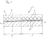
- FIG 1 shows the schematic view of a preferred embodiment of a retroreflective body 1.
- the retroreflective body 1 has a carrier 3, on the top 4 of which a binder layer 5 is applied, in which transparent balls 9 are introduced.
- a reflection layer 7 is arranged between the carrier 3 and the binder layer 5.
- the section of a retroreflective body shown schematically here has two partial areas I and II. Within the first partial area I, transparent balls 9 are embedded in the binder layer in such a way that sections of the balls, which are oriented towards the top 4 of the carrier, adjoin areas 8 at column 8.
- the retroreflective body also has a second partial area II.
- the transparent balls arranged here in the binder layer have no gap formation.
- individual transparent spheres also have a gap formation in the course of the second partial region II.
- the number of transparent spheres with gaps far exceeds the number of transparent spheres with gaps in the second area.
- a first portion of 10 to 90% of the transparent balls it is particularly preferred that 10 to 50% of the transparent balls have a gap formation, and it is very particularly preferred that a the first proportion of 20 to 30% of the transparent spheres have a gap formation.
- the second partial area II it is also possible for isolated transparent balls to have a gap. It is preferred that in the second partial area II a second portion is at most 50% of the first portion in the first partial area, preferably at most 30% and very particularly preferably at most 15%.
- the reflective layer in the first partial region I preferably has a reduced to no reflectivity compared to the second partial region II.
- the samples were cooled to a temperature of down to minus 196 ° C with the help of liquid nitrogen, which solidified the material and caused it to break, similar to a glass pane. Due to the very small dimensions of the glass ball, no breaks could be achieved through the glass balls. However, the method used was very effective for the other film layers and has achieved breaks in which the cross sections of the reflective film can be recognized very well. In order to avoid charging by the electron beam in electron microscopy, a thin layer of gold of approx. 30 nm was applied to the respective cross sections by means of sputtering. The samples were then connected to a grounded sample holder with the aid of a conductive adhesive tape, so that the charge carriers could be removed quickly.
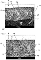
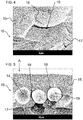
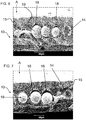
- FIG. 2 to 11 samples are shown as a microscopic cross section.
- the Figures 2 to 8 represents a retroreflective film 10, 10 * from the manufacturer 3M of the type "3M Scotchlite TM 4750 Oralite® 5100", which has been subjected to one of the abovementioned lasings. These samples have color effects in the lasered areas.
- the treated samples all have a detachment of the binder layer from the glass spheres in the lasered areas, which results in a space between the sphere and the binder layer.
- the untreated film as in the Figures 9 to 11 shown, has no detachment of the binder layer from the glass ball.
- the glass balls are completely embedded in the binder layer.
- the surface of the film in the direction of irradiation is designated with A, the film treated with the process according to the invention with 10, the untreated film with 10 *, the binder layer with 15, the glass ball with 19, impressions of the glass ball with 14, gaps between the binder layer and the sphere with 18, the reflection layer with 17 and the carrier with 13.
- the Figures 3 and 4 issue the slide Figure 2 in an enlargement.
- the gap 18 is approximately 10 microns long.
- FIG 5 A further retroreflective sheeting 10 is shown, which has been treated with the above-mentioned laser.
- the glass balls 19 have a clear delamination of the binder layer 15 and form a gap 18 between the binder layer 15 and the glass ball 19. This gap 18 extends even in this sample for the most part around the individual glass balls 19.
- the binder layer 15 has presumably partially detached from the sphere 19 and the gap 18 has formed.
- the Figure 9 the electron microscopic cross section through an untreated retroreflective film 10 * from the prior art.
- Untreated means that this film 10 * was not treated with the laser method mentioned above and does not have the color effects described above.
- this sample also has no gap or detachment of the binder layer 15 from the balls 19.
- the binder layer 15 consists of a polymer in which the individual glass balls 19 are completely embedded. At the breaking edge, the glass balls 19 protrude at least partially out of the binder layer 15. In some places, impressions 14 have remained in the binder layer 15, where individual glass balls failed during the cold break.
- This film 10 * has balls 19 with a diameter of approximately 50 ⁇ m, which are completely embedded in the binder layer.
Landscapes
- Physics & Mathematics (AREA)
- General Physics & Mathematics (AREA)
- Optics & Photonics (AREA)
- Engineering & Computer Science (AREA)
- Mechanical Engineering (AREA)
- Optical Elements Other Than Lenses (AREA)
Priority Applications (1)
| Application Number | Priority Date | Filing Date | Title |
|---|---|---|---|
| PL16793821T PL3371008T3 (pl) | 2015-11-05 | 2016-11-04 | Korpus odblaskowy z efektem barwnym i sposób wytwarzania |
Applications Claiming Priority (2)
| Application Number | Priority Date | Filing Date | Title |
|---|---|---|---|
| DE102015118966.6A DE102015118966A1 (de) | 2015-11-05 | 2015-11-05 | Retroreflektierender Körper mit Farbeffekt und Herstellungsverfahren |
| PCT/EP2016/076673 WO2017077033A1 (de) | 2015-11-05 | 2016-11-04 | Retroreflektierender körper mit farbeffekt und herstellungsverfahren |
Publications (2)
| Publication Number | Publication Date |
|---|---|
| EP3371008A1 EP3371008A1 (de) | 2018-09-12 |
| EP3371008B1 true EP3371008B1 (de) | 2020-01-01 |
Family
ID=57256289
Family Applications (1)
| Application Number | Title | Priority Date | Filing Date |
|---|---|---|---|
| EP16793821.6A Active EP3371008B1 (de) | 2015-11-05 | 2016-11-04 | Retroreflektierender körper mit farbeffekt und herstellungsverfahren |
Country Status (8)
| Country | Link |
|---|---|
| US (1) | US10723287B2 (pl) |
| EP (1) | EP3371008B1 (pl) |
| CN (1) | CN108349445A (pl) |
| BR (1) | BR112018008933A8 (pl) |
| CA (1) | CA3002497A1 (pl) |
| DE (1) | DE102015118966A1 (pl) |
| PL (1) | PL3371008T3 (pl) |
| WO (1) | WO2017077033A1 (pl) |
Families Citing this family (1)
| Publication number | Priority date | Publication date | Assignee | Title |
|---|---|---|---|---|
| GB202008165D0 (en) * | 2020-06-01 | 2020-07-15 | Bodle Tech Ltd | Method of applying a pattern, and security device for an article |
Family Cites Families (15)
| Publication number | Priority date | Publication date | Assignee | Title |
|---|---|---|---|---|
| US2713286A (en) * | 1949-10-22 | 1955-07-19 | Minnesota Mining & Mfg | Reflex light reflectors and glass bead elements thereof |
| US3190178A (en) | 1961-06-29 | 1965-06-22 | Minnesota Mining & Mfg | Reflex-reflecting sheeting |
| US3310900A (en) | 1963-10-04 | 1967-03-28 | Avery Products Corp | Retroreflective sign |
| US4123140A (en) * | 1977-06-30 | 1978-10-31 | Ferro Corporation | Reflecting sheeting having wide angle response |
| US4650283A (en) * | 1984-08-03 | 1987-03-17 | Minnesota Mining And Manufacturing Company | Directionally imaged retroreflective sheeting |
| CN1156426A (zh) * | 1994-07-26 | 1997-08-06 | 美国3M公司 | 回射图示制品和热转移制品 |
| US5726803A (en) * | 1994-09-30 | 1998-03-10 | Nippon Carbide Kogyo Kabushiki Kaisha | Lens-type retroreflective sheeting |
| US5882771A (en) * | 1996-04-10 | 1999-03-16 | Minnesota Mining And Manufacturing Company | Conformable embossable retroreflective sheeting |
| US5988821A (en) * | 1996-05-16 | 1999-11-23 | Nippon Carbide Kogyo Kabushiki Kaisha | Lens type functional retroreflective sheeting and method of producing same |
| US6586067B2 (en) * | 2001-04-02 | 2003-07-01 | Avery Dennison Corporation | Encapsulated lens retroreflective sheeting |
| CA2503305A1 (en) * | 2002-10-23 | 2004-05-06 | Zymogenetics, Inc. | Methods for treating viral infection using il-28 and il-29 |
| JP4800302B2 (ja) * | 2005-04-11 | 2011-10-26 | 日本カーバイド工業株式会社 | 印刷像が設置されている再帰反射シート |
| CN102576101B (zh) * | 2009-10-24 | 2015-01-14 | 3M创新有限公司 | 空隙化扩散体 |
| US20160154148A1 (en) | 2013-06-24 | 2016-06-02 | 3M Innovative Properties Company | Beaded retroreflective article with multilayer seal film |
| CN203630382U (zh) * | 2014-02-26 | 2014-06-04 | 台州市万创夜光明工贸有限公司 | 一种高耐水洗反光布 |
-
2015
- 2015-11-05 DE DE102015118966.6A patent/DE102015118966A1/de not_active Withdrawn
-
2016
- 2016-11-04 PL PL16793821T patent/PL3371008T3/pl unknown
- 2016-11-04 EP EP16793821.6A patent/EP3371008B1/de active Active
- 2016-11-04 CN CN201680064748.5A patent/CN108349445A/zh active Pending
- 2016-11-04 BR BR112018008933A patent/BR112018008933A8/pt not_active Application Discontinuation
- 2016-11-04 WO PCT/EP2016/076673 patent/WO2017077033A1/de not_active Ceased
- 2016-11-04 US US15/770,679 patent/US10723287B2/en active Active
- 2016-11-04 CA CA3002497A patent/CA3002497A1/en not_active Abandoned
Non-Patent Citations (1)
| Title |
|---|
| None * |
Also Published As
| Publication number | Publication date |
|---|---|
| DE102015118966A1 (de) | 2017-05-11 |
| BR112018008933A8 (pt) | 2019-02-26 |
| PL3371008T3 (pl) | 2020-06-15 |
| US10723287B2 (en) | 2020-07-28 |
| US20190054867A1 (en) | 2019-02-21 |
| EP3371008A1 (de) | 2018-09-12 |
| BR112018008933A2 (pt) | 2018-11-06 |
| CN108349445A (zh) | 2018-07-31 |
| CA3002497A1 (en) | 2017-05-11 |
| WO2017077033A1 (de) | 2017-05-11 |
Similar Documents
| Publication | Publication Date | Title |
|---|---|---|
| EP3820714B1 (de) | Optisch variables sicherheitselement mit reflektivem flächenbereich | |
| DE2542583C2 (de) | Retroreflektierende mehrschichtige Folie | |
| EP2665607B1 (de) | Verfahren zur herstellung eines mehrschichtigen datenträgers sowie nach diesem verfahren hergestellter datenträger | |
| EP2909040B1 (de) | Optisch variables flächenmuster | |
| EP2991837B1 (de) | Optisch variables sicherheitselement | |
| EP3820715B1 (de) | Optisch variables sicherheitselement mit reflektivem flächenbereich | |
| EP2838737B1 (de) | Optisch variables sicherheitselement | |
| EP3962733B1 (de) | Verbundscheibe mit einer aussparung in der innenscheibe | |
| DE3686293T2 (de) | Richtungsbildinformation enthaltende durchsichtige schicht und verfahren zu deren herstellung. | |
| EP2773514B1 (de) | Optisch variables sicherheitselement | |
| DE112015002704B4 (de) | Optisches Element | |
| DE202008017988U1 (de) | Transparente Anzeigevorrichtung mit Leiterbahnen, die mit undurchsichtiger Beschichtung versehen sind | |
| EP3337674A1 (de) | Wertdokument | |
| DE19923225B4 (de) | Optisches Element zur Umlenkung von Lichtstrahlen und Herstellungsverfahren | |
| WO2017055516A1 (de) | Retroreflektierendes schild, retroreflektierendes bandmaterial und verfahren zur herstellung | |
| EP3371008B1 (de) | Retroreflektierender körper mit farbeffekt und herstellungsverfahren | |
| EP3793838B1 (de) | Sicherheitselement mit bereichsweise metallisiertem flächenbereich, herstellungsverfahren und prägewerkzeug | |
| DE112018001866T5 (de) | Vordere Viereckseitenscheibe eines Fahrzeugs | |
| EP3738786A1 (de) | Lumineszierendes sicherheitselement | |
| WO2004088365A1 (de) | Selbstleuchtendes kfz-kennzeichen | |
| DE102018003603A1 (de) | Sicherheitselement, Datenträger und Verwendung | |
| DE102005062272B4 (de) | Windschutzscheibe und Fahrspurerkennungssystem für ein Kraftfahrzeug | |
| DE29700289U1 (de) | Flächenmuster | |
| WO2019210996A1 (de) | Retroreflektierende folie, folie, datenträger und verwendung | |
| DE10356297A1 (de) | Selbstleuchtendes Kfz-Kennzeichenschild |
Legal Events
| Date | Code | Title | Description |
|---|---|---|---|
| STAA | Information on the status of an ep patent application or granted ep patent |
Free format text: STATUS: UNKNOWN |
|
| STAA | Information on the status of an ep patent application or granted ep patent |
Free format text: STATUS: THE INTERNATIONAL PUBLICATION HAS BEEN MADE |
|
| PUAI | Public reference made under article 153(3) epc to a published international application that has entered the european phase |
Free format text: ORIGINAL CODE: 0009012 |
|
| STAA | Information on the status of an ep patent application or granted ep patent |
Free format text: STATUS: REQUEST FOR EXAMINATION WAS MADE |
|
| 17P | Request for examination filed |
Effective date: 20180412 |
|
| AK | Designated contracting states |
Kind code of ref document: A1 Designated state(s): AL AT BE BG CH CY CZ DE DK EE ES FI FR GB GR HR HU IE IS IT LI LT LU LV MC MK MT NL NO PL PT RO RS SE SI SK SM TR |
|
| AX | Request for extension of the european patent |
Extension state: BA ME |
|
| DAV | Request for validation of the european patent (deleted) | ||
| DAX | Request for extension of the european patent (deleted) | ||
| GRAP | Despatch of communication of intention to grant a patent |
Free format text: ORIGINAL CODE: EPIDOSNIGR1 |
|
| STAA | Information on the status of an ep patent application or granted ep patent |
Free format text: STATUS: GRANT OF PATENT IS INTENDED |
|
| INTG | Intention to grant announced |
Effective date: 20190729 |
|
| GRAS | Grant fee paid |
Free format text: ORIGINAL CODE: EPIDOSNIGR3 |
|
| GRAA | (expected) grant |
Free format text: ORIGINAL CODE: 0009210 |
|
| STAA | Information on the status of an ep patent application or granted ep patent |
Free format text: STATUS: THE PATENT HAS BEEN GRANTED |
|
| AK | Designated contracting states |
Kind code of ref document: B1 Designated state(s): AL AT BE BG CH CY CZ DE DK EE ES FI FR GB GR HR HU IE IS IT LI LT LU LV MC MK MT NL NO PL PT RO RS SE SI SK SM TR |
|
| REG | Reference to a national code |
Ref country code: GB Ref legal event code: FG4D Free format text: NOT ENGLISH |
|
| REG | Reference to a national code |
Ref country code: CH Ref legal event code: EP Ref country code: AT Ref legal event code: REF Ref document number: 1219400 Country of ref document: AT Kind code of ref document: T Effective date: 20200115 |
|
| REG | Reference to a national code |
Ref country code: DE Ref legal event code: R096 Ref document number: 502016008269 Country of ref document: DE |
|
| REG | Reference to a national code |
Ref country code: IE Ref legal event code: FG4D Free format text: LANGUAGE OF EP DOCUMENT: GERMAN |
|
| REG | Reference to a national code |
Ref country code: NL Ref legal event code: FP |
|
| REG | Reference to a national code |
Ref country code: LT Ref legal event code: MG4D |
|
| PG25 | Lapsed in a contracting state [announced via postgrant information from national office to epo] |
Ref country code: LT Free format text: LAPSE BECAUSE OF FAILURE TO SUBMIT A TRANSLATION OF THE DESCRIPTION OR TO PAY THE FEE WITHIN THE PRESCRIBED TIME-LIMIT Effective date: 20200101 Ref country code: RS Free format text: LAPSE BECAUSE OF FAILURE TO SUBMIT A TRANSLATION OF THE DESCRIPTION OR TO PAY THE FEE WITHIN THE PRESCRIBED TIME-LIMIT Effective date: 20200101 Ref country code: FI Free format text: LAPSE BECAUSE OF FAILURE TO SUBMIT A TRANSLATION OF THE DESCRIPTION OR TO PAY THE FEE WITHIN THE PRESCRIBED TIME-LIMIT Effective date: 20200101 Ref country code: CZ Free format text: LAPSE BECAUSE OF FAILURE TO SUBMIT A TRANSLATION OF THE DESCRIPTION OR TO PAY THE FEE WITHIN THE PRESCRIBED TIME-LIMIT Effective date: 20200101 Ref country code: PT Free format text: LAPSE BECAUSE OF FAILURE TO SUBMIT A TRANSLATION OF THE DESCRIPTION OR TO PAY THE FEE WITHIN THE PRESCRIBED TIME-LIMIT Effective date: 20200527 Ref country code: NO Free format text: LAPSE BECAUSE OF FAILURE TO SUBMIT A TRANSLATION OF THE DESCRIPTION OR TO PAY THE FEE WITHIN THE PRESCRIBED TIME-LIMIT Effective date: 20200401 |
|
| PG25 | Lapsed in a contracting state [announced via postgrant information from national office to epo] |
Ref country code: LV Free format text: LAPSE BECAUSE OF FAILURE TO SUBMIT A TRANSLATION OF THE DESCRIPTION OR TO PAY THE FEE WITHIN THE PRESCRIBED TIME-LIMIT Effective date: 20200101 Ref country code: SE Free format text: LAPSE BECAUSE OF FAILURE TO SUBMIT A TRANSLATION OF THE DESCRIPTION OR TO PAY THE FEE WITHIN THE PRESCRIBED TIME-LIMIT Effective date: 20200101 Ref country code: IS Free format text: LAPSE BECAUSE OF FAILURE TO SUBMIT A TRANSLATION OF THE DESCRIPTION OR TO PAY THE FEE WITHIN THE PRESCRIBED TIME-LIMIT Effective date: 20200501 Ref country code: BG Free format text: LAPSE BECAUSE OF FAILURE TO SUBMIT A TRANSLATION OF THE DESCRIPTION OR TO PAY THE FEE WITHIN THE PRESCRIBED TIME-LIMIT Effective date: 20200401 Ref country code: HR Free format text: LAPSE BECAUSE OF FAILURE TO SUBMIT A TRANSLATION OF THE DESCRIPTION OR TO PAY THE FEE WITHIN THE PRESCRIBED TIME-LIMIT Effective date: 20200101 Ref country code: GR Free format text: LAPSE BECAUSE OF FAILURE TO SUBMIT A TRANSLATION OF THE DESCRIPTION OR TO PAY THE FEE WITHIN THE PRESCRIBED TIME-LIMIT Effective date: 20200402 |
|
| REG | Reference to a national code |
Ref country code: DE Ref legal event code: R097 Ref document number: 502016008269 Country of ref document: DE |
|
| PG25 | Lapsed in a contracting state [announced via postgrant information from national office to epo] |
Ref country code: SK Free format text: LAPSE BECAUSE OF FAILURE TO SUBMIT A TRANSLATION OF THE DESCRIPTION OR TO PAY THE FEE WITHIN THE PRESCRIBED TIME-LIMIT Effective date: 20200101 Ref country code: RO Free format text: LAPSE BECAUSE OF FAILURE TO SUBMIT A TRANSLATION OF THE DESCRIPTION OR TO PAY THE FEE WITHIN THE PRESCRIBED TIME-LIMIT Effective date: 20200101 Ref country code: SM Free format text: LAPSE BECAUSE OF FAILURE TO SUBMIT A TRANSLATION OF THE DESCRIPTION OR TO PAY THE FEE WITHIN THE PRESCRIBED TIME-LIMIT Effective date: 20200101 Ref country code: EE Free format text: LAPSE BECAUSE OF FAILURE TO SUBMIT A TRANSLATION OF THE DESCRIPTION OR TO PAY THE FEE WITHIN THE PRESCRIBED TIME-LIMIT Effective date: 20200101 Ref country code: DK Free format text: LAPSE BECAUSE OF FAILURE TO SUBMIT A TRANSLATION OF THE DESCRIPTION OR TO PAY THE FEE WITHIN THE PRESCRIBED TIME-LIMIT Effective date: 20200101 Ref country code: ES Free format text: LAPSE BECAUSE OF FAILURE TO SUBMIT A TRANSLATION OF THE DESCRIPTION OR TO PAY THE FEE WITHIN THE PRESCRIBED TIME-LIMIT Effective date: 20200101 |
|
| PLBE | No opposition filed within time limit |
Free format text: ORIGINAL CODE: 0009261 |
|
| STAA | Information on the status of an ep patent application or granted ep patent |
Free format text: STATUS: NO OPPOSITION FILED WITHIN TIME LIMIT |
|
| 26N | No opposition filed |
Effective date: 20201002 |
|
| PG25 | Lapsed in a contracting state [announced via postgrant information from national office to epo] |
Ref country code: SI Free format text: LAPSE BECAUSE OF FAILURE TO SUBMIT A TRANSLATION OF THE DESCRIPTION OR TO PAY THE FEE WITHIN THE PRESCRIBED TIME-LIMIT Effective date: 20200101 |
|
| PG25 | Lapsed in a contracting state [announced via postgrant information from national office to epo] |
Ref country code: MC Free format text: LAPSE BECAUSE OF FAILURE TO SUBMIT A TRANSLATION OF THE DESCRIPTION OR TO PAY THE FEE WITHIN THE PRESCRIBED TIME-LIMIT Effective date: 20200101 |
|
| REG | Reference to a national code |
Ref country code: CH Ref legal event code: PL |
|
| GBPC | Gb: european patent ceased through non-payment of renewal fee |
Effective date: 20201104 |
|
| PG25 | Lapsed in a contracting state [announced via postgrant information from national office to epo] |
Ref country code: LU Free format text: LAPSE BECAUSE OF NON-PAYMENT OF DUE FEES Effective date: 20201104 |
|
| PG25 | Lapsed in a contracting state [announced via postgrant information from national office to epo] |
Ref country code: CH Free format text: LAPSE BECAUSE OF NON-PAYMENT OF DUE FEES Effective date: 20201130 Ref country code: LI Free format text: LAPSE BECAUSE OF NON-PAYMENT OF DUE FEES Effective date: 20201130 |
|
| PG25 | Lapsed in a contracting state [announced via postgrant information from national office to epo] |
Ref country code: FR Free format text: LAPSE BECAUSE OF NON-PAYMENT OF DUE FEES Effective date: 20201130 Ref country code: IE Free format text: LAPSE BECAUSE OF NON-PAYMENT OF DUE FEES Effective date: 20201104 |
|
| PG25 | Lapsed in a contracting state [announced via postgrant information from national office to epo] |
Ref country code: GB Free format text: LAPSE BECAUSE OF NON-PAYMENT OF DUE FEES Effective date: 20201104 |
|
| PGFP | Annual fee paid to national office [announced via postgrant information from national office to epo] |
Ref country code: NL Payment date: 20211119 Year of fee payment: 6 Ref country code: DE Payment date: 20211122 Year of fee payment: 6 |
|
| PGFP | Annual fee paid to national office [announced via postgrant information from national office to epo] |
Ref country code: IT Payment date: 20211130 Year of fee payment: 6 Ref country code: BE Payment date: 20211119 Year of fee payment: 6 |
|
| PGFP | Annual fee paid to national office [announced via postgrant information from national office to epo] |
Ref country code: PL Payment date: 20211026 Year of fee payment: 6 |
|
| PG25 | Lapsed in a contracting state [announced via postgrant information from national office to epo] |
Ref country code: TR Free format text: LAPSE BECAUSE OF FAILURE TO SUBMIT A TRANSLATION OF THE DESCRIPTION OR TO PAY THE FEE WITHIN THE PRESCRIBED TIME-LIMIT Effective date: 20200101 Ref country code: MT Free format text: LAPSE BECAUSE OF FAILURE TO SUBMIT A TRANSLATION OF THE DESCRIPTION OR TO PAY THE FEE WITHIN THE PRESCRIBED TIME-LIMIT Effective date: 20200101 Ref country code: CY Free format text: LAPSE BECAUSE OF FAILURE TO SUBMIT A TRANSLATION OF THE DESCRIPTION OR TO PAY THE FEE WITHIN THE PRESCRIBED TIME-LIMIT Effective date: 20200101 |
|
| PG25 | Lapsed in a contracting state [announced via postgrant information from national office to epo] |
Ref country code: MK Free format text: LAPSE BECAUSE OF FAILURE TO SUBMIT A TRANSLATION OF THE DESCRIPTION OR TO PAY THE FEE WITHIN THE PRESCRIBED TIME-LIMIT Effective date: 20200101 Ref country code: AL Free format text: LAPSE BECAUSE OF FAILURE TO SUBMIT A TRANSLATION OF THE DESCRIPTION OR TO PAY THE FEE WITHIN THE PRESCRIBED TIME-LIMIT Effective date: 20200101 |
|
| REG | Reference to a national code |
Ref country code: AT Ref legal event code: MM01 Ref document number: 1219400 Country of ref document: AT Kind code of ref document: T Effective date: 20211104 |
|
| PG25 | Lapsed in a contracting state [announced via postgrant information from national office to epo] |
Ref country code: AT Free format text: LAPSE BECAUSE OF NON-PAYMENT OF DUE FEES Effective date: 20211104 |
|
| REG | Reference to a national code |
Ref country code: DE Ref legal event code: R119 Ref document number: 502016008269 Country of ref document: DE |
|
| REG | Reference to a national code |
Ref country code: NL Ref legal event code: MM Effective date: 20221201 |
|
| REG | Reference to a national code |
Ref country code: BE Ref legal event code: MM Effective date: 20221130 |
|
| PG25 | Lapsed in a contracting state [announced via postgrant information from national office to epo] |
Ref country code: NL Free format text: LAPSE BECAUSE OF NON-PAYMENT OF DUE FEES Effective date: 20221201 |
|
| PG25 | Lapsed in a contracting state [announced via postgrant information from national office to epo] |
Ref country code: IT Free format text: LAPSE BECAUSE OF NON-PAYMENT OF DUE FEES Effective date: 20221104 Ref country code: DE Free format text: LAPSE BECAUSE OF NON-PAYMENT OF DUE FEES Effective date: 20230601 |
|
| PG25 | Lapsed in a contracting state [announced via postgrant information from national office to epo] |
Ref country code: BE Free format text: LAPSE BECAUSE OF NON-PAYMENT OF DUE FEES Effective date: 20221130 |
|
| PG25 | Lapsed in a contracting state [announced via postgrant information from national office to epo] |
Ref country code: PL Free format text: LAPSE BECAUSE OF NON-PAYMENT OF DUE FEES Effective date: 20221104 |