EP3370283A1 - Verfahren zur herstellung von elektroden mit gleichmässiger qualität und verfahren zur herstellung einer elektrodenanordnung damit - Google Patents
Verfahren zur herstellung von elektroden mit gleichmässiger qualität und verfahren zur herstellung einer elektrodenanordnung damit Download PDFInfo
- Publication number
- EP3370283A1 EP3370283A1 EP17849010.8A EP17849010A EP3370283A1 EP 3370283 A1 EP3370283 A1 EP 3370283A1 EP 17849010 A EP17849010 A EP 17849010A EP 3370283 A1 EP3370283 A1 EP 3370283A1
- Authority
- EP
- European Patent Office
- Prior art keywords
- electrode
- electrode mixture
- electrodes
- preparing
- coated layer
- Prior art date
- Legal status (The legal status is an assumption and is not a legal conclusion. Google has not performed a legal analysis and makes no representation as to the accuracy of the status listed.)
- Granted
Links
Images


Classifications
-
- H—ELECTRICITY
- H01—ELECTRIC ELEMENTS
- H01M—PROCESSES OR MEANS, e.g. BATTERIES, FOR THE DIRECT CONVERSION OF CHEMICAL ENERGY INTO ELECTRICAL ENERGY
- H01M10/00—Secondary cells; Manufacture thereof
- H01M10/05—Accumulators with non-aqueous electrolyte
- H01M10/052—Li-accumulators
-
- H—ELECTRICITY
- H01—ELECTRIC ELEMENTS
- H01M—PROCESSES OR MEANS, e.g. BATTERIES, FOR THE DIRECT CONVERSION OF CHEMICAL ENERGY INTO ELECTRICAL ENERGY
- H01M10/00—Secondary cells; Manufacture thereof
- H01M10/04—Construction or manufacture in general
- H01M10/0431—Cells with wound or folded electrodes
-
- H—ELECTRICITY
- H01—ELECTRIC ELEMENTS
- H01M—PROCESSES OR MEANS, e.g. BATTERIES, FOR THE DIRECT CONVERSION OF CHEMICAL ENERGY INTO ELECTRICAL ENERGY
- H01M10/00—Secondary cells; Manufacture thereof
- H01M10/05—Accumulators with non-aqueous electrolyte
- H01M10/058—Construction or manufacture
-
- H—ELECTRICITY
- H01—ELECTRIC ELEMENTS
- H01M—PROCESSES OR MEANS, e.g. BATTERIES, FOR THE DIRECT CONVERSION OF CHEMICAL ENERGY INTO ELECTRICAL ENERGY
- H01M4/00—Electrodes
- H01M4/02—Electrodes composed of, or comprising, active material
- H01M4/04—Processes of manufacture in general
-
- H—ELECTRICITY
- H01—ELECTRIC ELEMENTS
- H01M—PROCESSES OR MEANS, e.g. BATTERIES, FOR THE DIRECT CONVERSION OF CHEMICAL ENERGY INTO ELECTRICAL ENERGY
- H01M4/00—Electrodes
- H01M4/02—Electrodes composed of, or comprising, active material
- H01M4/04—Processes of manufacture in general
- H01M4/0402—Methods of deposition of the material
- H01M4/0404—Methods of deposition of the material by coating on electrode collectors
-
- H—ELECTRICITY
- H01—ELECTRIC ELEMENTS
- H01M—PROCESSES OR MEANS, e.g. BATTERIES, FOR THE DIRECT CONVERSION OF CHEMICAL ENERGY INTO ELECTRICAL ENERGY
- H01M4/00—Electrodes
- H01M4/02—Electrodes composed of, or comprising, active material
- H01M4/04—Processes of manufacture in general
- H01M4/043—Processes of manufacture in general involving compressing or compaction
- H01M4/0435—Rolling or calendering
-
- H—ELECTRICITY
- H01—ELECTRIC ELEMENTS
- H01M—PROCESSES OR MEANS, e.g. BATTERIES, FOR THE DIRECT CONVERSION OF CHEMICAL ENERGY INTO ELECTRICAL ENERGY
- H01M4/00—Electrodes
- H01M4/02—Electrodes composed of, or comprising, active material
- H01M4/13—Electrodes for accumulators with non-aqueous electrolyte, e.g. for lithium-accumulators; Processes of manufacture thereof
- H01M4/139—Processes of manufacture
-
- H—ELECTRICITY
- H01—ELECTRIC ELEMENTS
- H01M—PROCESSES OR MEANS, e.g. BATTERIES, FOR THE DIRECT CONVERSION OF CHEMICAL ENERGY INTO ELECTRICAL ENERGY
- H01M4/00—Electrodes
- H01M4/02—Electrodes composed of, or comprising, active material
- H01M4/64—Carriers or collectors
- H01M4/66—Selection of materials
- H01M4/661—Metal or alloys, e.g. alloy coatings
-
- H—ELECTRICITY
- H01—ELECTRIC ELEMENTS
- H01M—PROCESSES OR MEANS, e.g. BATTERIES, FOR THE DIRECT CONVERSION OF CHEMICAL ENERGY INTO ELECTRICAL ENERGY
- H01M4/00—Electrodes
- H01M4/02—Electrodes composed of, or comprising, active material
- H01M4/64—Carriers or collectors
- H01M4/70—Carriers or collectors characterised by shape or form
-
- H—ELECTRICITY
- H01—ELECTRIC ELEMENTS
- H01M—PROCESSES OR MEANS, e.g. BATTERIES, FOR THE DIRECT CONVERSION OF CHEMICAL ENERGY INTO ELECTRICAL ENERGY
- H01M10/00—Secondary cells; Manufacture thereof
- H01M10/05—Accumulators with non-aqueous electrolyte
- H01M10/058—Construction or manufacture
- H01M10/0585—Construction or manufacture of accumulators having only flat construction elements, i.e. flat positive electrodes, flat negative electrodes and flat separators
-
- H—ELECTRICITY
- H01—ELECTRIC ELEMENTS
- H01M—PROCESSES OR MEANS, e.g. BATTERIES, FOR THE DIRECT CONVERSION OF CHEMICAL ENERGY INTO ELECTRICAL ENERGY
- H01M4/00—Electrodes
- H01M4/02—Electrodes composed of, or comprising, active material
- H01M2004/026—Electrodes composed of, or comprising, active material characterised by the polarity
- H01M2004/027—Negative electrodes
-
- H—ELECTRICITY
- H01—ELECTRIC ELEMENTS
- H01M—PROCESSES OR MEANS, e.g. BATTERIES, FOR THE DIRECT CONVERSION OF CHEMICAL ENERGY INTO ELECTRICAL ENERGY
- H01M4/00—Electrodes
- H01M4/02—Electrodes composed of, or comprising, active material
- H01M2004/026—Electrodes composed of, or comprising, active material characterised by the polarity
- H01M2004/028—Positive electrodes
-
- Y—GENERAL TAGGING OF NEW TECHNOLOGICAL DEVELOPMENTS; GENERAL TAGGING OF CROSS-SECTIONAL TECHNOLOGIES SPANNING OVER SEVERAL SECTIONS OF THE IPC; TECHNICAL SUBJECTS COVERED BY FORMER USPC CROSS-REFERENCE ART COLLECTIONS [XRACs] AND DIGESTS
- Y02—TECHNOLOGIES OR APPLICATIONS FOR MITIGATION OR ADAPTATION AGAINST CLIMATE CHANGE
- Y02E—REDUCTION OF GREENHOUSE GAS [GHG] EMISSIONS, RELATED TO ENERGY GENERATION, TRANSMISSION OR DISTRIBUTION
- Y02E60/00—Enabling technologies; Technologies with a potential or indirect contribution to GHG emissions mitigation
- Y02E60/10—Energy storage using batteries
-
- Y—GENERAL TAGGING OF NEW TECHNOLOGICAL DEVELOPMENTS; GENERAL TAGGING OF CROSS-SECTIONAL TECHNOLOGIES SPANNING OVER SEVERAL SECTIONS OF THE IPC; TECHNICAL SUBJECTS COVERED BY FORMER USPC CROSS-REFERENCE ART COLLECTIONS [XRACs] AND DIGESTS
- Y02—TECHNOLOGIES OR APPLICATIONS FOR MITIGATION OR ADAPTATION AGAINST CLIMATE CHANGE
- Y02P—CLIMATE CHANGE MITIGATION TECHNOLOGIES IN THE PRODUCTION OR PROCESSING OF GOODS
- Y02P70/00—Climate change mitigation technologies in the production process for final industrial or consumer products
- Y02P70/50—Manufacturing or production processes characterised by the final manufactured product
Definitions
- the present disclosure relates to a method of preparing electrodes having uniform quality and a method of preparing an electrode assembly including the same.
- втори ⁇ ество have been widely used as energy sources for wireless mobile devices.
- secondary batteries are attracting attention as a power source for electric vehicles (EVs), hybrid EVs (HEVs), plug-in HEVs, and the like, which have been proposed as a solution to a problem of air pollution generated by conventional gasoline vehicles and diesel vehicles using fossil fuel.
- the secondary batteries are also used in power tools, electric bikes (E-bikes), electric scooters (E-scooters), electric golf carts, or power storage systems which require high output power.
- a prismatic type secondary battery and a pouch-type secondary battery that can be applied not only to products such as mobile phones having a thin thickness, but also to medium- and large-sized devices such as vehicles and electric power storage systems by a plurality of secondary batteries being combined and laminated in a middle- or large-sized pack structure.
- a material of the secondary battery there is a high demand for lithium secondary batteries such as lithium ion batteries and lithium ion polymer batteries having advantages such as high energy density, discharge voltage, output stability, and the like.
- secondary batteries may be classified according to a structure of an electrode assembly composed of a positive electrode, a negative electrode, and a separator.
- Typical examples are a jelly-roll type (wound type) electrode assembly having a structure in which long sheet-type positive electrodes and negative electrodes are wound while a separator is interposed between the positive electrode and negative electrode, a stacked type (laminated type) electrode assembly in which a large number of positive electrodes and negative electrodes cut in units of a predetermined size are sequentially laminated with a separator interposed between the positive electrode and negative electrode, and a stacked/folded type electrode assembly having a structure in which bi-cells or full cells in which predetermined units of positive and negative electrodes are laminated with a separator interposed between the positive electrode and negative electrode are wound.
- a process of preparing an electrode assembly having a laminated structure of a unit electrode includes a process of preparing positive and negative electrode mixtures, a process of applying each of the mixtures to a positive electrode current collector and a negative electrode current collector to prepare sheet type positive and negative electrodes, a process of forming an electrode tab on the electrodes, a process of rolling the electrodes, a process of slitting the electrodes to a desired size to prepare the electrodes, a process of vacuum drying, and a process of forming an electrode assembly composed of the prepared positive and negative electrodes and a separator.
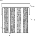
- FIG. 1 shows an electrode sheet according to the related art for preparing a single sheet of electrodes.
- an electrode sheet 10 is formed on a metal sheet in a state in which electrode lines 11 containing an electrode mixture are interposed between non-coated portions 12 which are uncoated areas.
- the electrode sheet 10 is rolled while a rolling roller 20 is rotated in a longitudinal direction corresponding to the electrode lines.
- a pressure is applied only to the electrode lines 11 but is not applied to the non-coated portions 12 between the electrode lines 11, and thus the entire electrode sheet 10 is stretched in a nonuniform manner. This is because the pressure applied to the electrode sheet 10 at the moment of rolling is not uniformly applied to the entire electrode sheet 10.
- shapes of the electrodes derived from the non-uniformly stretched electrode sheet may be slightly different.
- the present disclosure has been made to solve the above-described problems of the related art and technical problems which were identified in the past.
- the present disclosure is directed to provide a method of preparing electrodes capable of obtaining an electrode sheet having a uniform shape while improving preparation processability of the electrodes.
- the present disclosure provides a method of preparing an electrode for an electrode assembly having a structure in which electrodes are laminated, including:
- the rolling is performed in the second direction perpendicular to the electrode mixture coated layer lines parallel to the first direction, and thus only at least one electrode mixture coated layer line is rolled during the rolling process. That is, the rolling is performed in a state in which the rolling roller is in close contact with all of the electrode mixture coated layer lines at the moment of rolling, and thus a pressure may be uniformly applied to the entire sheet.
- the electrode base materials may be processed into a plurality of single electrodes at the same time that the electrode base materials are prepared by using a single machining apparatus, for example, an apparatus capable of cutting the electrode base materials and cutting the electrode base materials into the plurality of single electrodes.
- a width of the non-coated portion may be appropriately adjusted in consideration of a length of an electrode tab, and may generally be 5 mm to 20 mm, more preferably be 8 mm to 18 mm, and most preferably be 10 mm to 15 mm. When the width of the non-coated portion exceeds 20 mm, it is not preferable in terms of economic feasibility. However, as necessary, the width of the non-coated portion may not to be limited to the above ranges and be appropriately selected.
- the pressure applied to the electrode sheet is preferably in a range of 10 to 100 ton/cm 3 for a negative electrode and in a range of 30 to 300 ton/cm 3 for a positive electrode.
- a pressure lower than a lower limit value is applied to the electrode sheet, it is not preferable in terms of the electrical characteristics of the electrode.
- the pressure exceeding an upper limit value is applied, the electrode mixture may be broken, which is also not preferable.
- the processes (iii) and (iv) may be performed sequentially, and in this case, the two processes may be performed through a different processing apparatus.
- the process (iii) may further include a process of vacuum drying the electrode plate base material after the slitting process is performed.
- the first direction may be a direction corresponding to the width of the metal sheet on a plane
- the second direction may be a direction corresponding to the length of the metal sheet on the plane
- the electrode plate base material may have a structure in which the n electrode mixture coated layers are formed in the second direction with non-coated portions interposed therebetween.
- the non-coated portion of one side is cut in the first direction to have a shape of an electrode tab, and an end portion of an electrode mixture coated layer adjacent to the non-coated portion of the other side is simultaneously cut in the first direction to obtain an electrode from the electrode plate base material.
- a cutting margin may be secured by cutting a portion adjacent to the outer peripheral end portion of the electrode mixture coated layer.
- corners of both of the side end portions may also be chamfered.
- the metal sheet having a relatively long length with respect to its width is processed into a relatively small sized electrode base material to prepare an electrode, and thus a processing apparatus may be compactly designed.
- the electrode mixture may be a positive electrode mixture or a negative electrode mixture. Accordingly, the electrode preparing method according to the present disclosure may be used for preparing both a positive electrode and a negative electrode.
- the present disclosure also provides an electrode assembly preparing method including the electrode preparing method and an electrode assembly.
- electrodes prepared by the electrode preparing method are prepared to be an electrode assembly through subsequent processes.
- the subsequent processes may specifically be at least one process selected from:
- the process of laminating the electrodes with the separator interposed therebetween may be, as an example, a process of preparing an electrode assembly having a structure in which the electrodes are laminated while the electrodes are not in close contact with the separator by a single separator being interposed between the electrodes.
- the process of laminating the electrodes with the separator interposed therebetween may be a process of preparing an electrode assembly in which the electrodes are laminated while the electrodes are not in close contact with the separator by one separator being repeatedly bent from one direction to a direction opposite the one direction in a structure in which the one separator is passing through spaces between all of the electrodes.
- the present disclosure also provides battery cells including the electrode assembly.
- a type of a secondary battery of the present disclosure is not particularly limited, but specific examples thereof include a lithium-ion secondary battery, a lithium polymer secondary battery, a lithium ion polymer secondary battery, or the like which have advantages of high energy density, high discharge voltage, output stability, and the like.
- a lithium secondary battery is composed of a positive electrode, a negative electrode, a separator, and a nonaqueous electrolyte solution containing a lithium salt.
- the positive electrode is prepared, for example, by coating a mixture of a positive electrode active material, a conductive material, and a binder on a positive electrode current collector and/or an extended current collector and then drying the resultant, and a filler may be further added to the mixture as necessary.
- the positive electrode current collector and/or the extended current collect part may be generally manufactured to a thickness of 3 to 500 ⁇ m
- a material not inducing the chemical change and having a high conductivity may be used without limitation.
- the positive electrode current collector and the extended current collect part may include stainless steel, aluminum, nickel, titanium, sintered carbon, or an aluminum or stainless steel surface treated with carbon, nickel, titanium or silver.
- the positive electrode current collector may have fine irregularities on the surface thereof to increase an adhesiveness of the positive electrode active material, and may have various shapes such as a film, a sheet, a foil, a net, a porous body, a foam, and a non-woven fabric, etc.
- the conductive agent is generally added so that the conductive agent has 1 to 30 wt% based on the total weight of the compound including the positive electrode active material.
- the conductive agent is not particularly restricted so long as the conductive agent exhibits high conductivity while the conductive agent does not induce any chemical change in a battery to which the conductive agent is applied.
- graphite such as natural graphite or artificial graphite
- carbon black such as carbon black, acetylene black, Ketjen black, channel black, furnace black, lamp black, thermal black
- conductive fiber such as carbon fiber or metallic fiber
- metallic powder such as carbon fluoride powder, aluminum powder, or nickel powder
- conductive whisker such as zinc oxide or potassium titanate
- conductive metal oxide such as titanium oxide
- polyphenylene derivatives may be used as the conductive agent.
- the binder is a component assisting in binding between the active material and conductive agent and in binding with the current collector.
- the binder is generally added in an amount of 1 to 30 wt% based on the total weight of the compound including the positive electrode active material.
- the binder there may be used polyvinylidene fluoride, polyvinyl alcohol, carboxymethylcellulose (CMC), starch, hydroxypropylcellulose, regenerated cellulose, polyvinyl pyrollidone, tetrafluoroethylene, polyethylene, polypropylene, ethylene-propylene-diene terpolymer (EPDM), sulfonated EPDM, styrene butadiene rubber, fluoro rubber, and various copolymers.
- the filler is an optional component used to inhibit expansion of the positive electrode.
- the filler there is no particular limit to the filler so long as the filler does not cause chemical changes in a battery to which the filler is applied, and is made of a fibrous material.
- the filler there may be used olefin polymers, such as polyethylene and polypropylene; and fibrous materials, such as glass fiber and carbon fiber.
- the negative electrode may be prepared by applying and drying a negative electrode active material to a negative electrode current collector and/or an extended current collect part.
- the above-mentioned components may be selectively added to the negative electrode active material as needed.
- the negative electrode current collector and/or the extended current collect part may be generally manufactured to a thickness of about 3 to 500 ⁇ m.
- a material not inducing chemical change and having conductivity may be used without limitation.
- Examples of the negative electrode current collector and the extended current collect part may include copper, stainless steel, aluminum, nickel, titanium, baked carbon, or copper or stainless steel surface-treated with carbon, nickel, titanium, silver, etc., aluminum-cadmium ally, etc.
- the negative electrode current collector and/or the extended current collect part may have fine irregularities on the surface thereof to increase an adhesiveness of the negative electrode active material, and may have various shapes such as a film, a sheet, a foil, a net, a porous body, a foam, and a non-woven fabric, etc.
- the negative electrode active material for example, there may be used carbon, such as non-graphitizing carbon or a graphite-based carbon; a metal composite oxide, such as Li x Fe 2 O 3 (0 ⁇ x ⁇ 1), Li x WO 2 (0 ⁇ x ⁇ 1), Sn x Me 1-x Me' y O z (Me: Mn, Fe, Pb, Ge; Me': Al, B, P, Si, Group 1, 2 and 3 elements of the periodic table, halogen; 0 ⁇ x ⁇ 1; 1 ⁇ y ⁇ 3; 1 ⁇ z ⁇ 8); lithium metal; lithium alloy; silicon-based alloy; tin-based alloy; a metal oxide, such as SnO, SnO 2 , PbO, PbO 2 , Pb 2 O 3 , Pb 3 O 4 , Sb 2 O 3 , Sb 2 O 4 , Sb 2 O 5 , GeO, GeO 2 , Bi 2 O 3 , Bi 2 O 4 , or Bi 2 O 5 ; conductive polymer, such as poly
- the separator is interposed between the positive electrode and the negative electrode, and an insulating thin film having high ion permeability and mechanical strength is used.
- a pore diameter of the separator is generally 0.01 to 10 ⁇ m, and a thickness thereof is generally 5 to 300 ⁇ m.
- olefin-based polymers such as polypropylene, which is chemically resistant and hydrophobic; a sheet or a non-woven fabric made of glass fiber, polyethylene or the like may be used as an example of the separator.
- the solid electrolyte such as a polymer
- the solid electrolyte may also serve as a separator.
- the electrolytic solution may be a non-aqueous electrolytic solution containing a lithium salt, and may include a non-aqueous electrolytic solution and a lithium salt.
- the non-aqueous electrolytic solution may include non-aqueous organic solvent, organic solid electrolyte, inorganic solid electrolyte, etc., but may not be limited thereof.
- non-protic organic solvents such as N-methyl-2-pyrollidinone, propylene carbonate, ethylene carbonate, butylene carbonate, dimethyl carbonate, diethyl carbonate, gamma-butyro lactone, 1,2-dimethoxy ethane, tetrahydroxy Franc, 2-methyl tetrahydrofuran, dimethylsulfoxide, 1,3-dioxolane, formamide, dimethylformamide, dioxolane, acetonitrile, nitromethane, methyl formate, methyl acetate, phosphoric acid triester, trimethoxy methane, dioxolane derivatives, sulfolane, methyl sulfolane, 1,3-dimethyl-2-imidazolidinone, propylene carbonate derivatives, tetrahydrofuran derivatives, ether, methyl propionate, and ethyl propionate
- non-protic organic solvents such as N-methyl-2-pyr
- organic solid electrolyte examples include polyethylene derivatives, polyethylene oxide derivatives, polypropylene oxide derivatives, phosphoric acid ester polymers, poly agitation lysine, polyester sulfide, polyvinyl alcohols, polyvinylidene fluoride, and polymers containing ionic dissociation groups.
- lithium Li
- Li lithium
- Li nitrides, halides, and sulphates of lithium (Li), such as Li 3 N, Lil, Li 5 NI 2 , Li 3 N-LiI-LiOH, LiSiO 4 , LiSiO 4 -LiI-LiOH, Li 2 SiS 3 , Li 4 SiO 4 , Li 4 SiO 4 -LiI-LiOH, and Li 3 PO 4 -Li 2 S-SiS 2 .
- Li lithium
- the lithium salt is a material that is readily soluble in the above-mentioned non-aqueous electrolyte, and may include, for example, LiCl, LiBr, Lil, LiClO 4 , LiBF 4 , LiB 10 Cl 10 , LiPF 6 , LiCF 3 SO 3 , LiCF 3 CO 2 , LiAsF 6 , LiSbF 6 , LiAlCl 4 , CH 3 SO 3 Li, CF 3 SO 3 Li, (CF 3 SO 2 ) 2 NLi, chloroborane lithium, lower aliphatic carboxylic acid lithium, lithium tetraphenyl borate, and imide.
- pyridine triethylphosphite, triethanolamine, cyclic ether, ethylenediamine, n-glyme, hexaphosphoric triamide, nitrobenzene derivatives, sulfur, quinone imine dyes, N-substituted oxazolidinone, N,N-substituted imidazolidine, ethylene glycol dialkyl ether, ammonium salts, pyrrole, 2-methoxy ethanol, aluminum trichloride, or the like may be added to the non-aqueous electrolytic solution.
- the non-aqueous electrolytic solution may further include halogen-containing solvents, such as carbon tetrachloride and ethylene trifluoride.
- the non-aqueous electrolytic solution may further include carbon dioxide gas, and may further include fluoroethylene carbonate(FEC), propene sultone(PRS), etc.
- a non-aqueous electrolyte containing a lithium salt may be prepared by adding a lithium salt such as LiPF 6 , LiClO 4 , LiBF 4 , LiN(SO 2 CF 3 ) 2 , etc. to a mixed solvent of a cyclic carbonate of EC or PC, which is a high-dielectric solvent, and a linear carbonate of DEC, DMC or EMC, which is a low viscosity solvent.
- a lithium salt such as LiPF 6 , LiClO 4 , LiBF 4 , LiN(SO 2 CF 3 ) 2 , etc.
- rolling is performed in a second direction perpendicular to electrode mixture coated layer lines parallel to a first direction, and thus only at least one electrode mixture coated layer line is rolled during the rolling. That is, the rolling is performed in a state in which a rolling roller is in close contact with the entire electrode mixture coated layer line at the moment of rolling, and thus a pressure can be uniformly applied to an entire sheet.
- FIG. 1 shows a process of preparing an electrode by line coating an electrode sheet according to the related art.
- an electrode sheet 10 is formed on a metal sheet in a state in which electrode lines 11 containing an electrode mixture are interposed between non-coated portions 12 which are uncoated areas.
- the electrode sheet 10 is rolled while a rolling roller 20 is rotated in a longitudinal direction corresponding to the electrode lines. In this process, a pressure is applied only to the electrode lines 11 but is not applied to the non-coated portions 12 between the electrode lines 11, and thus the entire electrode sheet 10 is stretched in a non-uniform manner.
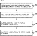
- FIG. 2 is a flow chart showing an electrode preparing method according to one embodiment of the present disclosure.
- the electrode mixture is coated on a metal sheet 210 in a process 110 to form a plurality of electrode mixture coated layer lines 211, 222, 213 and 214. Thereafter, a process 120 of rolling the metal sheet 210 with a rolling roller 220 is performed. Therefore, a rolling is performed in a state in which the rolling roller 220 is in close contact with all of the electrode mixture coated layer lines 211, 212, 213 and 214 at the moment of rolling, and thus a pressure may be uniformly applied to the entire sheet.
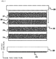
- FIG. 3 With FIG. 2 , in which the metal sheet 210 according to one embodiment of the present disclosure is shown.
- the electrode mixture is coated on one surface of the electrically conductive metal sheet 210 along the first direction so that the electrode mixture coated layer lines 211, 212, 213 and 214 are formed parallel to the first direction with the non-coated portion 201 interposed therebetween.
- the coating of the electrode mixture may be performed through a coater having a plurality of nozzles formed therein.
- the electrode mixture discharged through the nozzles of the coater may be applied in parallel with each other on the metal sheet 210, and the electrode mixture coated layer lines 211, 212, 213 and 214 having the non-coated portion 201 therebetween may be formed.
- the first direction is a direction corresponding to a width of the metal sheet 210 on a plane.
- the metal sheet 210 on which the electrode mixture coated layer lines 211, 212, 213 and 214 are formed is rolled by the rolling roller 220 in a following process 120.
- the rolling roller 220 is rotated in a second direction perpendicular to the first direction and the metal sheet 210 is rolled while being moved in the direction opposite to the rotating direction of the rolling roller 220.
- the second direction is a direction corresponding to a length of the metal sheet 210 on a plane, and a moving direction of the metal sheet 210 by the rolling roller 220 may be also understood as the second direction.
- the rolling is performed in the second direction perpendicular to the electrode mixture coated layer lines 211, 212, 213 and 214 parallel to the first direction, so that the rolling is performed in a state in which the rolling roller 220 is in close contact with all of the electrode mixture coated layer lines 211, 212, 213 and 214 at the moment of rolling, and thus a pressure may be uniformly applied to the entire sheet.
- a stretching degree of the electrode mixture coated layer lines may be uniform.
- a process 130 of slitting the rolled metal sheet 210 to prepare an electrode base material 300 and a process 140 of cutting the electrode base material 300 and obtaining a single electrode by notching and cutting are performed.
- FIG. 7 is a schematic diagram showing processes of slitting and notching a metal sheet according to the related art.
- a coated electrode sheet is wound and supplied in a roll unit, and the non-coated portion of the side is processed to form a tab through the notching process.
- a mold having a shape of a unit electrode is used to cut out a remainder while leaving a part of the metal thin plate for connecting the electrodes in the non-coated portion, and the process may be performed using a laser.
- the electrode sheet subjected to the notching process is rewound, and the rewound electrode sheet is fed to the cutting process.
- the electrode sheet is cut into unit electrodes using the cutter or the laser.
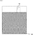
- FIG. 8 shows a process of slitting the metal sheet rolled according to the present disclosure in the second direction to obtain an electrode place base material
- FIG. 9 shows a notching and cutting process with the electrode plate base material obtained through the process of FIG. 8 .
- a plurality of perforated lines a-a' corresponding to the second direction are set in the metal sheet 210 rolled in the process 120, and then the metal sheet is slit along the perforated lines.
- the slit metal sheet 210 is defined as an electrode base material 300 in the present disclosure.
- the electrode base material 300 has a structure in which four electrode mixture coated layers that are same as the number of the electrode mixture coated layer lines 211, 212, 213 and 214 are formed along the second direction with the non-coated portion 201 therebetween.
- Metal base materials 300 obtained from one metal sheet 210 in the process 130 are respectively process into a single electrode corresponding to the number of electrode mixture coated layers 301, 302, 303 and 304 included therein.
- the non-coated portion 305 of one side is cut in the first direction so as to have the shape of the electrode tab 321 and an end part of the electrode mixture coated layer 301 adjacent to the non-coated portion 306 of the other side is cut in the first direction, thereby obtaining an electrode from the electrode base material 300.
- a roll-shaped electrode base material sheet is cut into unit electrodes at once while moving.
- the rolled-up electrode base material sheet is continuously fed to a press having a mold whose shape coincides with the shape of the end part and the tab of the unit electrode while being spread, and cut by the mold to obtain unit electrodes.
- a thickness of the electrode mixture coated layer may be thinner that a center portion of the electrode mixture coated layer.
- the thinner portion is removed by the cutting margin and thus is not included in the electrode, the thickness of the electrode may be relatively uniform.
- corners of both of the side end portions may be also chamfered.
Landscapes
- Chemical & Material Sciences (AREA)
- Engineering & Computer Science (AREA)
- Chemical Kinetics & Catalysis (AREA)
- Electrochemistry (AREA)
- General Chemical & Material Sciences (AREA)
- Manufacturing & Machinery (AREA)
- Materials Engineering (AREA)
- Battery Electrode And Active Subsutance (AREA)
Priority Applications (1)
| Application Number | Priority Date | Filing Date | Title |
|---|---|---|---|
| PL17849010T PL3370283T3 (pl) | 2016-09-08 | 2017-08-28 | Sposób przygotowania elektrod mających jednolitą jakość i sposób przygotowania zespołu elektrod je zawierający |
Applications Claiming Priority (3)
| Application Number | Priority Date | Filing Date | Title |
|---|---|---|---|
| KR20160115781 | 2016-09-08 | ||
| KR1020170105860A KR102079929B1 (ko) | 2016-09-08 | 2017-08-22 | 균일한 품질을 가지는 전극들의 제조 방법 및 이를 포함하는 전극조립체 제조 방법 |
| PCT/KR2017/009368 WO2018048126A1 (ko) | 2016-09-08 | 2017-08-28 | 균일한 품질을 가지는 전극들의 제조 방법 및 이를 포함하는 전극조립체 제조 방법 |
Publications (3)
| Publication Number | Publication Date |
|---|---|
| EP3370283A1 true EP3370283A1 (de) | 2018-09-05 |
| EP3370283A4 EP3370283A4 (de) | 2019-02-27 |
| EP3370283B1 EP3370283B1 (de) | 2020-09-30 |
Family
ID=61910229
Family Applications (1)
| Application Number | Title | Priority Date | Filing Date |
|---|---|---|---|
| EP17849010.8A Active EP3370283B1 (de) | 2016-09-08 | 2017-08-28 | Verfahren zur herstellung von elektroden mit gleichmässiger qualität und verfahren zur herstellung einer elektrodenanordnung damit |
Country Status (4)
| Country | Link |
|---|---|
| EP (1) | EP3370283B1 (de) |
| KR (1) | KR102079929B1 (de) |
| CN (1) | CN108292743B (de) |
| PL (1) | PL3370283T3 (de) |
Cited By (4)
| Publication number | Priority date | Publication date | Assignee | Title |
|---|---|---|---|---|
| EP4095964A4 (de) * | 2020-06-10 | 2024-01-10 | LG Energy Solution, Ltd. | Verfahren zur herstellung einer elektrode mit einer falteinheit und elektrodenblech mit einer falteinheit |
| EP4086997A4 (de) * | 2020-06-08 | 2024-01-17 | LG Energy Solution, Ltd. | Verfahren zur herstellung einer elektrode mit einem faltteil und elektrodenblatt mit einem faltteil |
| SE2251077A1 (en) * | 2022-09-16 | 2024-03-17 | Northvolt Ab | A method of manufacturing a secondary cell electrode |
| EP3525265B1 (de) * | 2017-03-13 | 2024-06-12 | LG Energy Solution, Ltd. | Verfahren zur herstellung einer sekundärbatterieelektrode |
Families Citing this family (5)
| Publication number | Priority date | Publication date | Assignee | Title |
|---|---|---|---|---|
| KR102751961B1 (ko) * | 2018-11-20 | 2025-01-10 | 주식회사 엘지에너지솔루션 | 전극 조립체 제조장치 및 전극 조립체 제조방법 |
| KR102446291B1 (ko) * | 2019-10-31 | 2022-09-22 | 삼성에스디아이 주식회사 | 전극판 제조 방법 및 이를 통해 제조된 전극판 |
| KR102926760B1 (ko) | 2020-02-07 | 2026-02-11 | 주식회사 엘지에너지솔루션 | 레이저를 이용한 클리닝 단계를 포함하는 전극 제조방법, 상기 방법으로 제조된 전극 및 이를 포함하는 이차전지 |
| US20230158701A1 (en) * | 2020-07-14 | 2023-05-25 | Lg Energy Solution, Ltd. | Electrode Cutting Device and Method and Electrode Manufacturing Apparatus Comprising the Same |
| CN115332475A (zh) * | 2022-08-30 | 2022-11-11 | 珠海冠宇电池股份有限公司 | 一种电池极片制作方法、电池极片和锂离子电池 |
Family Cites Families (3)
| Publication number | Priority date | Publication date | Assignee | Title |
|---|---|---|---|---|
| JP5159007B2 (ja) * | 2001-05-11 | 2013-03-06 | パナソニック株式会社 | 電池用極板の製造方法 |
| JP2007329050A (ja) * | 2006-06-08 | 2007-12-20 | Mitsubishi Cable Ind Ltd | シート状電池及びその製造方法 |
| JP2016139561A (ja) * | 2015-01-28 | 2016-08-04 | 株式会社豊田自動織機 | プレス装置及び電極の製造方法 |
-
2017
- 2017-08-22 KR KR1020170105860A patent/KR102079929B1/ko active Active
- 2017-08-28 EP EP17849010.8A patent/EP3370283B1/de active Active
- 2017-08-28 CN CN201780004257.6A patent/CN108292743B/zh active Active
- 2017-08-28 PL PL17849010T patent/PL3370283T3/pl unknown
Cited By (5)
| Publication number | Priority date | Publication date | Assignee | Title |
|---|---|---|---|---|
| EP3525265B1 (de) * | 2017-03-13 | 2024-06-12 | LG Energy Solution, Ltd. | Verfahren zur herstellung einer sekundärbatterieelektrode |
| EP4086997A4 (de) * | 2020-06-08 | 2024-01-17 | LG Energy Solution, Ltd. | Verfahren zur herstellung einer elektrode mit einem faltteil und elektrodenblatt mit einem faltteil |
| EP4095964A4 (de) * | 2020-06-10 | 2024-01-10 | LG Energy Solution, Ltd. | Verfahren zur herstellung einer elektrode mit einer falteinheit und elektrodenblech mit einer falteinheit |
| SE2251077A1 (en) * | 2022-09-16 | 2024-03-17 | Northvolt Ab | A method of manufacturing a secondary cell electrode |
| SE546431C2 (en) * | 2022-09-16 | 2024-10-29 | Northvolt Ab | A method of manufacturing an electrode for a tab-less secondary cell |
Also Published As
| Publication number | Publication date |
|---|---|
| EP3370283A4 (de) | 2019-02-27 |
| KR102079929B1 (ko) | 2020-02-21 |
| PL3370283T3 (pl) | 2021-03-08 |
| EP3370283B1 (de) | 2020-09-30 |
| KR20180028369A (ko) | 2018-03-16 |
| CN108292743B (zh) | 2021-02-12 |
| CN108292743A (zh) | 2018-07-17 |
Similar Documents
| Publication | Publication Date | Title |
|---|---|---|
| EP3370283B1 (de) | Verfahren zur herstellung von elektroden mit gleichmässiger qualität und verfahren zur herstellung einer elektrodenanordnung damit | |
| US11283101B2 (en) | Method of preparing electrodes having uniform quality and electrode assembly preparation method including the same | |
| EP3432404B1 (de) | Verfahren zur herstellung einer stapel-/faltelektrodenanordnung | |
| KR102316074B1 (ko) | 이차 전지용 전극 제조방법 및 그에 따라 제조된 이차 전지용 전극 | |
| US9099721B2 (en) | High-power lithium secondary battery | |
| KR20130105001A (ko) | 신규한 구조의 전극 제조장치 | |
| CN103765653B (zh) | 具有优异生产率和安全性的二次电池 | |
| KR20170055722A (ko) | 노칭부를 포함하는 전극 시트를 이용하여 전극판을 제조하는 방법 | |
| KR102314029B1 (ko) | 고로딩 전극의 제조 방법 | |
| KR20180097243A (ko) | 전극판들의 정렬하는 과정을 포함하는 전극조립체의 제조방법 | |
| KR20170022289A (ko) | 활물질 로딩량의 구배를 가진 전극을 포함하는 전극조립체 | |
| EP3370281B1 (de) | Elektrode mit elektrodenstromkollektor einer dreidimensionalen netzwerkstruktur | |
| KR102198496B1 (ko) | 전기 용량 증대와 용접 기능성 향상이 동시에 구현 가능한 전극의 제조 방법 | |
| KR102000539B1 (ko) | 면적이 상이한 코팅부들을 포함하는 단위 전극 시트를 이용하여 이차전지용 전극판을 제조하는 방법 | |
| EP3367480B1 (de) | Verfahren zur herstellung einer sekundärbatterie, einschliesslich einer elektrode mit hoher kapazität | |
| KR20170043240A (ko) | 집전체 중심 부위에 높은 활물질 로딩량을 가지는 전극을 포함하는 전극조립체 | |
| KR102070907B1 (ko) | 충방전 시 발생하는 가스를 수용할 수 있는 잉여부를 포함하는 전지셀 | |
| KR101852765B1 (ko) | 비정형 전극 시트 및 형태 변형이 가능한 구조의 비정형 전극조립체 | |
| KR101636451B1 (ko) | 로딩량이 다른 활물질층을 포함하고 있는 젤리-롤 | |
| KR20130105382A (ko) | 젤리-롤형 전극조립체, 이를 포함하는 리튬 이차 전지 및 그 제조방법 | |
| KR20180081228A (ko) | 단위셀의 위치에 따라 기공률이 상이한 전극을 포함하는 전극조립체 | |
| EP3312910A1 (de) | Verfahren zur herstellung einer elektrode für sekundärbatterie mit trocknungsprozess für elektrodenschlamm durch vakuum in spezifischer richtung |
Legal Events
| Date | Code | Title | Description |
|---|---|---|---|
| STAA | Information on the status of an ep patent application or granted ep patent |
Free format text: STATUS: THE INTERNATIONAL PUBLICATION HAS BEEN MADE |
|
| PUAI | Public reference made under article 153(3) epc to a published international application that has entered the european phase |
Free format text: ORIGINAL CODE: 0009012 |
|
| STAA | Information on the status of an ep patent application or granted ep patent |
Free format text: STATUS: REQUEST FOR EXAMINATION WAS MADE |
|
| 17P | Request for examination filed |
Effective date: 20180528 |
|
| AK | Designated contracting states |
Kind code of ref document: A1 Designated state(s): AL AT BE BG CH CY CZ DE DK EE ES FI FR GB GR HR HU IE IS IT LI LT LU LV MC MK MT NL NO PL PT RO RS SE SI SK SM TR |
|
| AX | Request for extension of the european patent |
Extension state: BA ME |
|
| A4 | Supplementary search report drawn up and despatched |
Effective date: 20190124 |
|
| RIC1 | Information provided on ipc code assigned before grant |
Ipc: H01M 4/04 20060101ALI20190118BHEP Ipc: H01M 4/139 20100101AFI20190118BHEP Ipc: H01M 10/052 20100101ALN20190118BHEP Ipc: H01M 10/04 20060101ALI20190118BHEP Ipc: H01M 10/0585 20100101ALN20190118BHEP |
|
| DAV | Request for validation of the european patent (deleted) | ||
| DAX | Request for extension of the european patent (deleted) | ||
| GRAP | Despatch of communication of intention to grant a patent |
Free format text: ORIGINAL CODE: EPIDOSNIGR1 |
|
| STAA | Information on the status of an ep patent application or granted ep patent |
Free format text: STATUS: GRANT OF PATENT IS INTENDED |
|
| RIC1 | Information provided on ipc code assigned before grant |
Ipc: H01M 10/052 20100101ALN20200421BHEP Ipc: H01M 4/04 20060101ALI20200421BHEP Ipc: H01M 10/0585 20100101ALN20200421BHEP Ipc: H01M 4/139 20100101AFI20200421BHEP Ipc: H01M 10/04 20060101ALI20200421BHEP |
|
| INTG | Intention to grant announced |
Effective date: 20200518 |
|
| GRAS | Grant fee paid |
Free format text: ORIGINAL CODE: EPIDOSNIGR3 |
|
| GRAA | (expected) grant |
Free format text: ORIGINAL CODE: 0009210 |
|
| STAA | Information on the status of an ep patent application or granted ep patent |
Free format text: STATUS: THE PATENT HAS BEEN GRANTED |
|
| AK | Designated contracting states |
Kind code of ref document: B1 Designated state(s): AL AT BE BG CH CY CZ DE DK EE ES FI FR GB GR HR HU IE IS IT LI LT LU LV MC MK MT NL NO PL PT RO RS SE SI SK SM TR |
|
| REG | Reference to a national code |
Ref country code: CH Ref legal event code: EP Ref country code: GB Ref legal event code: FG4D |
|
| REG | Reference to a national code |
Ref country code: DE Ref legal event code: R096 Ref document number: 602017024800 Country of ref document: DE Ref country code: AT Ref legal event code: REF Ref document number: 1319719 Country of ref document: AT Kind code of ref document: T Effective date: 20201015 |
|
| REG | Reference to a national code |
Ref country code: IE Ref legal event code: FG4D |
|
| PG25 | Lapsed in a contracting state [announced via postgrant information from national office to epo] |
Ref country code: FI Free format text: LAPSE BECAUSE OF FAILURE TO SUBMIT A TRANSLATION OF THE DESCRIPTION OR TO PAY THE FEE WITHIN THE PRESCRIBED TIME-LIMIT Effective date: 20200930 Ref country code: NO Free format text: LAPSE BECAUSE OF FAILURE TO SUBMIT A TRANSLATION OF THE DESCRIPTION OR TO PAY THE FEE WITHIN THE PRESCRIBED TIME-LIMIT Effective date: 20201230 Ref country code: GR Free format text: LAPSE BECAUSE OF FAILURE TO SUBMIT A TRANSLATION OF THE DESCRIPTION OR TO PAY THE FEE WITHIN THE PRESCRIBED TIME-LIMIT Effective date: 20201231 Ref country code: SE Free format text: LAPSE BECAUSE OF FAILURE TO SUBMIT A TRANSLATION OF THE DESCRIPTION OR TO PAY THE FEE WITHIN THE PRESCRIBED TIME-LIMIT Effective date: 20200930 Ref country code: HR Free format text: LAPSE BECAUSE OF FAILURE TO SUBMIT A TRANSLATION OF THE DESCRIPTION OR TO PAY THE FEE WITHIN THE PRESCRIBED TIME-LIMIT Effective date: 20200930 Ref country code: BG Free format text: LAPSE BECAUSE OF FAILURE TO SUBMIT A TRANSLATION OF THE DESCRIPTION OR TO PAY THE FEE WITHIN THE PRESCRIBED TIME-LIMIT Effective date: 20201230 |
|
| REG | Reference to a national code |
Ref country code: AT Ref legal event code: MK05 Ref document number: 1319719 Country of ref document: AT Kind code of ref document: T Effective date: 20200930 |
|
| PG25 | Lapsed in a contracting state [announced via postgrant information from national office to epo] |
Ref country code: LV Free format text: LAPSE BECAUSE OF FAILURE TO SUBMIT A TRANSLATION OF THE DESCRIPTION OR TO PAY THE FEE WITHIN THE PRESCRIBED TIME-LIMIT Effective date: 20200930 Ref country code: RS Free format text: LAPSE BECAUSE OF FAILURE TO SUBMIT A TRANSLATION OF THE DESCRIPTION OR TO PAY THE FEE WITHIN THE PRESCRIBED TIME-LIMIT Effective date: 20200930 |
|
| REG | Reference to a national code |
Ref country code: NL Ref legal event code: MP Effective date: 20200930 |
|
| REG | Reference to a national code |
Ref country code: LT Ref legal event code: MG4D |
|
| PG25 | Lapsed in a contracting state [announced via postgrant information from national office to epo] |
Ref country code: LT Free format text: LAPSE BECAUSE OF FAILURE TO SUBMIT A TRANSLATION OF THE DESCRIPTION OR TO PAY THE FEE WITHIN THE PRESCRIBED TIME-LIMIT Effective date: 20200930 Ref country code: SM Free format text: LAPSE BECAUSE OF FAILURE TO SUBMIT A TRANSLATION OF THE DESCRIPTION OR TO PAY THE FEE WITHIN THE PRESCRIBED TIME-LIMIT Effective date: 20200930 Ref country code: CZ Free format text: LAPSE BECAUSE OF FAILURE TO SUBMIT A TRANSLATION OF THE DESCRIPTION OR TO PAY THE FEE WITHIN THE PRESCRIBED TIME-LIMIT Effective date: 20200930 Ref country code: PT Free format text: LAPSE BECAUSE OF FAILURE TO SUBMIT A TRANSLATION OF THE DESCRIPTION OR TO PAY THE FEE WITHIN THE PRESCRIBED TIME-LIMIT Effective date: 20210201 Ref country code: RO Free format text: LAPSE BECAUSE OF FAILURE TO SUBMIT A TRANSLATION OF THE DESCRIPTION OR TO PAY THE FEE WITHIN THE PRESCRIBED TIME-LIMIT Effective date: 20200930 Ref country code: EE Free format text: LAPSE BECAUSE OF FAILURE TO SUBMIT A TRANSLATION OF THE DESCRIPTION OR TO PAY THE FEE WITHIN THE PRESCRIBED TIME-LIMIT Effective date: 20200930 |
|
| PG25 | Lapsed in a contracting state [announced via postgrant information from national office to epo] |
Ref country code: ES Free format text: LAPSE BECAUSE OF FAILURE TO SUBMIT A TRANSLATION OF THE DESCRIPTION OR TO PAY THE FEE WITHIN THE PRESCRIBED TIME-LIMIT Effective date: 20200930 Ref country code: AT Free format text: LAPSE BECAUSE OF FAILURE TO SUBMIT A TRANSLATION OF THE DESCRIPTION OR TO PAY THE FEE WITHIN THE PRESCRIBED TIME-LIMIT Effective date: 20200930 Ref country code: AL Free format text: LAPSE BECAUSE OF FAILURE TO SUBMIT A TRANSLATION OF THE DESCRIPTION OR TO PAY THE FEE WITHIN THE PRESCRIBED TIME-LIMIT Effective date: 20200930 Ref country code: IS Free format text: LAPSE BECAUSE OF FAILURE TO SUBMIT A TRANSLATION OF THE DESCRIPTION OR TO PAY THE FEE WITHIN THE PRESCRIBED TIME-LIMIT Effective date: 20210130 |
|
| PG25 | Lapsed in a contracting state [announced via postgrant information from national office to epo] |
Ref country code: SK Free format text: LAPSE BECAUSE OF FAILURE TO SUBMIT A TRANSLATION OF THE DESCRIPTION OR TO PAY THE FEE WITHIN THE PRESCRIBED TIME-LIMIT Effective date: 20200930 Ref country code: NL Free format text: LAPSE BECAUSE OF FAILURE TO SUBMIT A TRANSLATION OF THE DESCRIPTION OR TO PAY THE FEE WITHIN THE PRESCRIBED TIME-LIMIT Effective date: 20200930 |
|
| REG | Reference to a national code |
Ref country code: DE Ref legal event code: R097 Ref document number: 602017024800 Country of ref document: DE |
|
| PLBE | No opposition filed within time limit |
Free format text: ORIGINAL CODE: 0009261 |
|
| STAA | Information on the status of an ep patent application or granted ep patent |
Free format text: STATUS: NO OPPOSITION FILED WITHIN TIME LIMIT |
|
| PG25 | Lapsed in a contracting state [announced via postgrant information from national office to epo] |
Ref country code: DK Free format text: LAPSE BECAUSE OF FAILURE TO SUBMIT A TRANSLATION OF THE DESCRIPTION OR TO PAY THE FEE WITHIN THE PRESCRIBED TIME-LIMIT Effective date: 20200930 |
|
| 26N | No opposition filed |
Effective date: 20210701 |
|
| PG25 | Lapsed in a contracting state [announced via postgrant information from national office to epo] |
Ref country code: IT Free format text: LAPSE BECAUSE OF FAILURE TO SUBMIT A TRANSLATION OF THE DESCRIPTION OR TO PAY THE FEE WITHIN THE PRESCRIBED TIME-LIMIT Effective date: 20200930 |
|
| PG25 | Lapsed in a contracting state [announced via postgrant information from national office to epo] |
Ref country code: SI Free format text: LAPSE BECAUSE OF FAILURE TO SUBMIT A TRANSLATION OF THE DESCRIPTION OR TO PAY THE FEE WITHIN THE PRESCRIBED TIME-LIMIT Effective date: 20200930 |
|
| REG | Reference to a national code |
Ref country code: CH Ref legal event code: PL |
|
| PG25 | Lapsed in a contracting state [announced via postgrant information from national office to epo] |
Ref country code: MC Free format text: LAPSE BECAUSE OF FAILURE TO SUBMIT A TRANSLATION OF THE DESCRIPTION OR TO PAY THE FEE WITHIN THE PRESCRIBED TIME-LIMIT Effective date: 20200930 |
|
| REG | Reference to a national code |
Ref country code: BE Ref legal event code: MM Effective date: 20210831 |
|
| PG25 | Lapsed in a contracting state [announced via postgrant information from national office to epo] |
Ref country code: LI Free format text: LAPSE BECAUSE OF NON-PAYMENT OF DUE FEES Effective date: 20210831 Ref country code: CH Free format text: LAPSE BECAUSE OF NON-PAYMENT OF DUE FEES Effective date: 20210831 |
|
| PG25 | Lapsed in a contracting state [announced via postgrant information from national office to epo] |
Ref country code: IS Free format text: LAPSE BECAUSE OF FAILURE TO SUBMIT A TRANSLATION OF THE DESCRIPTION OR TO PAY THE FEE WITHIN THE PRESCRIBED TIME-LIMIT Effective date: 20210130 Ref country code: LU Free format text: LAPSE BECAUSE OF NON-PAYMENT OF DUE FEES Effective date: 20210828 |
|
| PG25 | Lapsed in a contracting state [announced via postgrant information from national office to epo] |
Ref country code: IE Free format text: LAPSE BECAUSE OF NON-PAYMENT OF DUE FEES Effective date: 20210828 Ref country code: BE Free format text: LAPSE BECAUSE OF NON-PAYMENT OF DUE FEES Effective date: 20210831 |
|
| P01 | Opt-out of the competence of the unified patent court (upc) registered |
Effective date: 20230512 |
|
| PG25 | Lapsed in a contracting state [announced via postgrant information from national office to epo] |
Ref country code: CY Free format text: LAPSE BECAUSE OF FAILURE TO SUBMIT A TRANSLATION OF THE DESCRIPTION OR TO PAY THE FEE WITHIN THE PRESCRIBED TIME-LIMIT Effective date: 20200930 |
|
| PG25 | Lapsed in a contracting state [announced via postgrant information from national office to epo] |
Ref country code: HU Free format text: LAPSE BECAUSE OF FAILURE TO SUBMIT A TRANSLATION OF THE DESCRIPTION OR TO PAY THE FEE WITHIN THE PRESCRIBED TIME-LIMIT; INVALID AB INITIO Effective date: 20170828 |
|
| REG | Reference to a national code |
Ref country code: GB Ref legal event code: 732E Free format text: REGISTERED BETWEEN 20230824 AND 20230831 |
|
| REG | Reference to a national code |
Ref country code: DE Ref legal event code: R081 Ref document number: 602017024800 Country of ref document: DE Owner name: LG ENERGY SOLUTION, LTD., KR Free format text: FORMER OWNER: LG CHEM. LTD., SEOUL, KR |
|
| PG25 | Lapsed in a contracting state [announced via postgrant information from national office to epo] |
Ref country code: MK Free format text: LAPSE BECAUSE OF FAILURE TO SUBMIT A TRANSLATION OF THE DESCRIPTION OR TO PAY THE FEE WITHIN THE PRESCRIBED TIME-LIMIT Effective date: 20200930 |
|
| PG25 | Lapsed in a contracting state [announced via postgrant information from national office to epo] |
Ref country code: MT Free format text: LAPSE BECAUSE OF FAILURE TO SUBMIT A TRANSLATION OF THE DESCRIPTION OR TO PAY THE FEE WITHIN THE PRESCRIBED TIME-LIMIT Effective date: 20200930 |
|
| PGFP | Annual fee paid to national office [announced via postgrant information from national office to epo] |
Ref country code: DE Payment date: 20250721 Year of fee payment: 9 |
|
| PGFP | Annual fee paid to national office [announced via postgrant information from national office to epo] |
Ref country code: PL Payment date: 20250725 Year of fee payment: 9 |
|
| PGFP | Annual fee paid to national office [announced via postgrant information from national office to epo] |
Ref country code: GB Payment date: 20250722 Year of fee payment: 9 |
|
| PGFP | Annual fee paid to national office [announced via postgrant information from national office to epo] |
Ref country code: FR Payment date: 20250725 Year of fee payment: 9 |
|
| PG25 | Lapsed in a contracting state [announced via postgrant information from national office to epo] |
Ref country code: TR Free format text: LAPSE BECAUSE OF FAILURE TO SUBMIT A TRANSLATION OF THE DESCRIPTION OR TO PAY THE FEE WITHIN THE PRESCRIBED TIME-LIMIT Effective date: 20200930 |