EP3370039B1 - Kraftfahrzeug-rohrleitung mit einem mischelement aus einer drahtstruktur - Google Patents
Kraftfahrzeug-rohrleitung mit einem mischelement aus einer drahtstruktur Download PDFInfo
- Publication number
- EP3370039B1 EP3370039B1 EP18158638.9A EP18158638A EP3370039B1 EP 3370039 B1 EP3370039 B1 EP 3370039B1 EP 18158638 A EP18158638 A EP 18158638A EP 3370039 B1 EP3370039 B1 EP 3370039B1
- Authority
- EP
- European Patent Office
- Prior art keywords
- pipeline
- mixing element
- gas
- band
- wire
- Prior art date
- Legal status (The legal status is an assumption and is not a legal conclusion. Google has not performed a legal analysis and makes no representation as to the accuracy of the status listed.)
- Active
Links
Images


Classifications
-
- F—MECHANICAL ENGINEERING; LIGHTING; HEATING; WEAPONS; BLASTING
- F02—COMBUSTION ENGINES; HOT-GAS OR COMBUSTION-PRODUCT ENGINE PLANTS
- F02M—SUPPLYING COMBUSTION ENGINES IN GENERAL WITH COMBUSTIBLE MIXTURES OR CONSTITUENTS THEREOF
- F02M35/00—Combustion-air cleaners, air intakes, intake silencers, or induction systems specially adapted for, or arranged on, internal-combustion engines
- F02M35/10—Air intakes; Induction systems
- F02M35/10242—Devices or means connected to or integrated into air intakes; Air intakes combined with other engine or vehicle parts
- F02M35/10262—Flow guides, obstructions, deflectors or the like
-
- F—MECHANICAL ENGINEERING; LIGHTING; HEATING; WEAPONS; BLASTING
- F02—COMBUSTION ENGINES; HOT-GAS OR COMBUSTION-PRODUCT ENGINE PLANTS
- F02D—CONTROLLING COMBUSTION ENGINES
- F02D41/00—Electrical control of supply of combustible mixture or its constituents
- F02D41/02—Circuit arrangements for generating control signals
- F02D41/18—Circuit arrangements for generating control signals by measuring intake air flow
-
- F—MECHANICAL ENGINEERING; LIGHTING; HEATING; WEAPONS; BLASTING
- F02—COMBUSTION ENGINES; HOT-GAS OR COMBUSTION-PRODUCT ENGINE PLANTS
- F02M—SUPPLYING COMBUSTION ENGINES IN GENERAL WITH COMBUSTIBLE MIXTURES OR CONSTITUENTS THEREOF
- F02M35/00—Combustion-air cleaners, air intakes, intake silencers, or induction systems specially adapted for, or arranged on, internal-combustion engines
- F02M35/10—Air intakes; Induction systems
- F02M35/10242—Devices or means connected to or integrated into air intakes; Air intakes combined with other engine or vehicle parts
- F02M35/10295—Damping means, e.g. tranquillising chamber to dampen air oscillations
-
- F—MECHANICAL ENGINEERING; LIGHTING; HEATING; WEAPONS; BLASTING
- F02—COMBUSTION ENGINES; HOT-GAS OR COMBUSTION-PRODUCT ENGINE PLANTS
- F02M—SUPPLYING COMBUSTION ENGINES IN GENERAL WITH COMBUSTIBLE MIXTURES OR CONSTITUENTS THEREOF
- F02M35/00—Combustion-air cleaners, air intakes, intake silencers, or induction systems specially adapted for, or arranged on, internal-combustion engines
- F02M35/10—Air intakes; Induction systems
- F02M35/10314—Materials for intake systems
- F02M35/10334—Foams; Fabrics; Porous media; Laminates; Ceramics; Coatings
-
- F—MECHANICAL ENGINEERING; LIGHTING; HEATING; WEAPONS; BLASTING
- F02—COMBUSTION ENGINES; HOT-GAS OR COMBUSTION-PRODUCT ENGINE PLANTS
- F02M—SUPPLYING COMBUSTION ENGINES IN GENERAL WITH COMBUSTIBLE MIXTURES OR CONSTITUENTS THEREOF
- F02M35/00—Combustion-air cleaners, air intakes, intake silencers, or induction systems specially adapted for, or arranged on, internal-combustion engines
- F02M35/10—Air intakes; Induction systems
- F02M35/10373—Sensors for intake systems
- F02M35/10386—Sensors for intake systems for flow rate
-
- F—MECHANICAL ENGINEERING; LIGHTING; HEATING; WEAPONS; BLASTING
- F15—FLUID-PRESSURE ACTUATORS; HYDRAULICS OR PNEUMATICS IN GENERAL
- F15D—FLUID DYNAMICS, i.e. METHODS OR MEANS FOR INFLUENCING THE FLOW OF GASES OR LIQUIDS
- F15D1/00—Influencing flow of fluids
- F15D1/001—Flow of fluid from conduits such as pipes, sleeves, tubes, with equal distribution of fluid flow over the evacuation surface
-
- F—MECHANICAL ENGINEERING; LIGHTING; HEATING; WEAPONS; BLASTING
- F15—FLUID-PRESSURE ACTUATORS; HYDRAULICS OR PNEUMATICS IN GENERAL
- F15D—FLUID DYNAMICS, i.e. METHODS OR MEANS FOR INFLUENCING THE FLOW OF GASES OR LIQUIDS
- F15D1/00—Influencing flow of fluids
- F15D1/02—Influencing flow of fluids in pipes or conduits
- F15D1/025—Influencing flow of fluids in pipes or conduits by means of orifice or throttle elements
-
- G—PHYSICS
- G01—MEASURING; TESTING
- G01F—MEASURING VOLUME, VOLUME FLOW, MASS FLOW OR LIQUID LEVEL; METERING BY VOLUME
- G01F1/00—Measuring the volume flow or mass flow of fluid or fluent solid material wherein the fluid passes through a meter in a continuous flow
- G01F1/76—Devices for measuring mass flow of a fluid or a fluent solid material
-
- G—PHYSICS
- G01—MEASURING; TESTING
- G01F—MEASURING VOLUME, VOLUME FLOW, MASS FLOW OR LIQUID LEVEL; METERING BY VOLUME
- G01F15/00—Details of, or accessories for, apparatus of groups G01F1/00 - G01F13/00 insofar as such details or appliances are not adapted to particular types of such apparatus
-
- B—PERFORMING OPERATIONS; TRANSPORTING
- B60—VEHICLES IN GENERAL
- B60Y—INDEXING SCHEME RELATING TO ASPECTS CROSS-CUTTING VEHICLE TECHNOLOGY
- B60Y2400/00—Special features of vehicle units
- B60Y2400/30—Sensors
- B60Y2400/3018—Flow-meters
-
- B—PERFORMING OPERATIONS; TRANSPORTING
- B60—VEHICLES IN GENERAL
- B60Y—INDEXING SCHEME RELATING TO ASPECTS CROSS-CUTTING VEHICLE TECHNOLOGY
- B60Y2400/00—Special features of vehicle units
- B60Y2400/43—Engines
-
- Y—GENERAL TAGGING OF NEW TECHNOLOGICAL DEVELOPMENTS; GENERAL TAGGING OF CROSS-SECTIONAL TECHNOLOGIES SPANNING OVER SEVERAL SECTIONS OF THE IPC; TECHNICAL SUBJECTS COVERED BY FORMER USPC CROSS-REFERENCE ART COLLECTIONS [XRACs] AND DIGESTS
- Y02—TECHNOLOGIES OR APPLICATIONS FOR MITIGATION OR ADAPTATION AGAINST CLIMATE CHANGE
- Y02T—CLIMATE CHANGE MITIGATION TECHNOLOGIES RELATED TO TRANSPORTATION
- Y02T10/00—Road transport of goods or passengers
- Y02T10/10—Internal combustion engine [ICE] based vehicles
- Y02T10/12—Improving ICE efficiencies
Definitions
- the invention relates to a pipeline for supplying a gas, in particular air, to an internal combustion engine, having a pipeline cross section forming a passage for the gas, and a gas measuring device (preferably gas mass measuring device) for measuring a gas mass flow.
- a gas measuring device preferably gas mass measuring device
- US 5,918,279 A discloses a device for measuring the mass of a flowing medium, comprising a measuring element and a grid provided upstream of the measuring element having a plurality of flow openings, wherein the flow openings at least partially have a different flow cross-section and the flow cross-sections of the flow openings adapted to the inflow to the grid in that there is a flow with a substantially uniform velocity distribution downstream of the grid.
- the air mass supplied to the internal combustion engines must be recorded as accurately as possible.
- air mass meters are mainly used in pipelines that work on the hot-wire or hot film principle.
- the flow velocity of the air is usually measured only occasionally in the pipe cross-section.
- the measurement usually takes place along a line in the pipe cross-section. Since measurements are only carried out in a very small area of the pipe cross section, the measurement results are strongly dependent on the flow profile present in the pipe cross section.
- the airfoil is usually uneven / inhomogeneous, z. B. caused by disturbances such as curved pipe sections, installation tolerances, aging and deformation of components, etc.
- An object of the invention is to increase the accuracy of the measurement of a gas mass flow in a pipeline for supplying a gas to an internal combustion engine.
- the invention relates to a z. B. substantially rigid or flexible pipe for supplying a gas (in particular air) to an internal combustion engine, preferably a motor vehicle, in particular a commercial vehicle (eg., Bus or truck).
- a gas in particular air
- an internal combustion engine preferably a motor vehicle, in particular a commercial vehicle (eg., Bus or truck).
- the pipeline comprises a pipeline cross section forming a passage for the gas and a gas measuring device (eg gas mass measuring device) for measuring a gas mass flow (eg a gas mass sensor, a measuring device operating according to the hot wire or hot film principle or at least an ultrasonic sensor, etc.).
- a gas measuring device eg gas mass measuring device
- gas mass flow eg a gas mass sensor, a measuring device operating according to the hot wire or hot film principle or at least an ultrasonic sensor, etc.
- the gas measuring device is expediently used for measuring the gas mass flow and in particular for measuring the flow velocity of the gas mass flow.
- the invention is characterized in particular in that the pipeline comprises a mixing element made of a wire structure upstream of the gas measuring device and the mixing element for influencing, preferably for mixing, the gas is used to homogenize an existing inhomogeneous (gas) flow profile upstream of the mixing element, so preferably the inhomogeneity at least reduced or preferably can be substantially completely eliminated.
- the mixing element may preferably homogenize the inhomogeneous flow profile so that it is in a z. B. is converted over at least the majority of the pipe cross section expedient substantially homogeneous flow profile.
- the mixing element thus acts in particular such that unequal distributions in the flow profile over the pipe cross-section are at least reduced by (preferably substantially complete) thorough mixing of the gas stream, so that after flowing through the gas through the mixing element as homogeneous a flow profile (over the preferably substantially entire Pipe section) is present.
- the wire structure comprises at least one wire mesh or at least one wire mesh.
- the wire structure comprises a rolled-up band of wire mesh or wire mesh.
- a rolled-up band of wire mesh or wire mesh can serve to form the mixing element.
- the wire mesh comprises a wire mesh tube. The wire mesh tube is flattened into a ribbon and the ribbon is rolled up to form the mixing element.
- the tape can z. B. include a fabric or fabric strips and / or a z. B. have substantially horizontally oriented and / or substantially planar original form.
- embossing z. B. is oriented obliquely and / or not perpendicular relative to the roller plane of the band.
- a z. B. perpendicular to the roller plane of the tape-oriented embossing is disadvantageous because when rolling the band embossing increases can fall into each other.
- the embossing can z. B. a substantially oblique pattern, V-pattern (in particular arrow pattern) or substantially W-pattern form, in particular to increase the stability at z. B. wide bands.
- the embossing is preferably carried out as Crugewellung.
- the mixing element z. B. have a substantially uniform density and / or a substantially homogeneous structure.
- the tape can be z. B. be rolled up in counterblow, expedient so that at least two superimposed layers of the tape are expedient coiled up from a tape end together.
- the tape can be rolled up z. B. form individual layers and it is z. B. possible that the individual layers have embossments preferably with different and / or opposite orientation.
- the tape When the tape is rolled up in the counter-stroke, the tape is first at least once repelled to preferably approximately half the length, and then the at least two layers are co-rolled together.
- embossing increases of individual rolled layers of the tape may have a different, in particular opposite, orientation and thus expediently no longer fall into each other, whereby preferably a mixing element with substantially uniform density and / or a substantially homogeneous structure can be formed.
- the tape When rolling up the tape in the same stroke, the tape is rolled up in only one layer from one end of the tape, so that embossing increases individual rolled layers of the tape have the same orientation and thus can fall into each other.
- two open ends of the tape are disposed on outer sides of the tape, e.g. B. offset by 180 ° +/- 40 °, +/- 30 ° or +/- 20 ° to each other, so that z. B. the mixing element has a substantially symmetrical edge region.
- the mixing element has an asymmetrical edge region.
- the mixing element and thus in particular the wire structure can fill the substantially entire pipe cross-section.
- the mixing element acts as a swirling device, so that turbulences of the gas at wire sections of the wire structure provide for the mixing of the gas and the homogenization of the inhomogeneous flow profile.
- a gas flow at the outlet of the mixing element can thus z. B. have a plurality of preferably small vertebrae. Alternatively or additionally, a gas flow on Outlet of the mixing element to be more swirled than at the entrance of the mixing element. Despite or just because of the turbulence, a homogeneous flow profile can be made possible.
- the eddies downstream of the mixing element may decay (in particular reduce) a substantially linear (expediently straight) settling section for the gas and / or at least one rectifier device (eg a rectifier grid) for reducing the eddies and thus achieving them a substantially laminar gas flow is formed.
- a substantially linear (expediently straight) settling section for the gas and / or at least one rectifier device eg a rectifier grid
- a rectifier device for reducing the vortex can, for example. be arranged in or immediately before a gas inlet (eg, gas inlet of a measuring tube) of the gas measuring device.
- a gas inlet eg, gas inlet of a measuring tube
- wire sections of the wire mesh prefferably be arranged so as to intersect at random and / or successively at an arbitrary angle, so that preferably the gas is deflected several times during the flow through the mixing element.
- the deflection can take place in preferably all three spatial directions.
- wire sections of at least two wire fabric layers are successively arranged crossing one another in an arbitrary angle, so that preferably the gas is deflected several times during the flow through the mixing element.
- the deflection can take place in preferably all three spatial directions.
- the pipeline may have at least one impingement upstream of the mixing element, the impingement causing the gas upstream of the mixing element to have an inhomogeneous / uneven flow profile over the pipeline cross-section.
- the pipeline may be curved upstream of the mixing element and the curvature may cause the gas upstream of the mixing element to have an inhomogeneous / non-uniform flow profile over the pipeline cross-section.
- the mixing element, the calming section and / or at least one rectifier device is preferably arranged upstream of the gas measuring device in the pipeline.
- a gas filter may be arranged to filter the gas.
- the wire structure is preferably formed of a metal material, in particular stainless steel.
- the wire structure may in the context of the invention but also z. B. be formed of a plastic material.
- the wire mesh is at least partially knitted from preferably a single wire, in particular metal and / or plastic wire.
- the gas is, as already mentioned, preferably air.
- the gas measuring device is thus preferably an air measuring device.
- the gas measuring device is preferably used for measuring the (gas) flow rate.
- the feature “homogenize” and / or “homogeneous” preferably comprises embodiments in which an inhomogeneity is substantially completely eliminated, but also preferably embodiments in which an inhomogeneity is expediently substantially reduced only.
- the feature “homogenize” and / or “homogeneous” is thus preferably not limited to a complete homogenization of an inhomogeneous flow profile. Also z. As a substantially rotationally symmetrical about the pipe center axis flow profile may be useful in the context of the invention by the feature "homogeneous” and / or “homogenize” includes.
- the invention also includes a motor vehicle, preferably a utility vehicle (eg, bus or truck) with a pipeline according to one of the preceding claims.
- a motor vehicle preferably a utility vehicle (eg, bus or truck) with a pipeline according to one of the preceding claims.
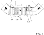
- FIG. 1 shows a view of a pipe 1 for supplying a gas in the form of air to an internal combustion engine, not shown, according to an embodiment of the invention.
- the arrows P indicate the flow direction of the gas through the pipeline 1.
- the in FIG. 1 left part of the pipe 1 forms a clean air pipe from a gas filter, not shown, wherein the in FIG. 1 right part of the pipe 1 forms a clean air pipe to the engine.
- the pipeline 1 comprises a passage for the gas-forming pipeline cross section D and a gas measuring device 2 for measuring a gas mass flow.
- the gas measuring device 2 preferably operates on the hot-film or heating wire principle or else with at least one ultrasonic sensor. Other measuring devices known in the art may also be used.
- the gas measuring device 2 expediently measures the flow velocity only selectively, so that a flow profile which is as homogeneous as possible over the pipe cross-section D for an accurate measurement is advantageous.
- Reference symbol S1 denotes a flow profile upstream of a mixing element 3 described in more detail below.
- FIG. 1 shows that the flow profile S1 is inhomogeneous and thus uneven, in particular caused by the curvature in the FIG. 1 left part of the pipeline 1.
- Other Störbeetzmaschineschungen can lead to an inhomogeneous flow profile S1, z.
- a mixing element 3 with an inlet 3.1 and an outlet 3.2 for the gas is installed in the pipeline 1 upstream of the gas measuring device 2.
- the mixing element 3 is formed from a metallic or plastic-like wire structure and serves to mix the gas in order to homogenize the inhomogeneous flow profile S1 present upstream of the mixing element 3, so that its inhomogeneity is at least reduced, preferably substantially eliminated.
- the mixing element 3 acts in such a way that the inhomogeneous flow profile S1 is converted into a flow profile S2 which is substantially homogeneous over the pipe cross-section D.
- the mixing element 3 fills the entire pipe cross-section D and acts in particular as a swirling device, so that the thorough mixing of the gas and thus the homogenization by swirling of the gas takes place on wire sections of the wire structure.
- the gas flow at the outlet 3.2 of the mixing element 3 thus has a multiplicity of relatively small vortices. Embodiments are even possible in which the gas flow at the outlet 3.2 of the mixing element 3 is more fluidized than at the inlet 3.1 of the mixing element 3.
- the pipeline 1 comprises a substantially linear calming section 4 within which the vortices decay can.
- the pipe 1 comprises two optional rectifier grids 5.1 and 5.2, which also serve to reduce the vortex downstream of the mixing element 3.
- the rectifier grid 5.2 is expediently arranged in or immediately before a gas inlet of the gas measuring device 2, preferably in or immediately in front of its measuring tube.
- the aim of the mixing element 3 is therefore to eliminate unequal distributions in the flow profile over the pipe cross-section D by (for example substantially complete) thorough mixing of the gas stream, so that after flowing through the mixing element 3 as homogeneous a flow profile S2 over the preferably substantially entire Pipe cross-section D is present.
- This can be achieved in particular by a deliberately induced turbulence of the gas on wire sections of the wire structure.
- the mixing element 3 consequently serves in particular for homogenizing an inhomogeneous flow profile and, in contrast to vortex suppression devices customary in the prior art, preferably not for converting a turbulent gas flow into a more laminar gas flow.
- the mixing element 3 is designed with a substantially uniform density and a substantially homogeneous structure.
- the mixing element 3 is arranged upstream of the calming section 4 and the two optional rectifier gratings 5.1 and 5.2 in the pipeline 1.
- the mixing element 3, the calming section 4 and the two optional rectifier gratings 5.1 and 5.2 are arranged upstream of the gas measuring device 2 in the pipeline 1.
- FIG. 2 shows a section of a mixing element 3 made of wire mesh according to an embodiment of the invention.
- FIG. 2 It can be seen that wire sections of the wire mesh are arranged in random orientation and one behind the other crossing, so that the gas during the flow through the mixing element 3 several times, preferably in all three spatial directions, deflected and thus effectively swirled and / or mixed, which in FIG. 2 is indicated schematically by the arrows within the mixing element 3.
- FIG. 3 shows a section of a wire mesh for forming a mixing element 3 according to an embodiment of the invention.
- At least two such wire mesh can z. B. are arranged one behind the other, so that their wire sections intersect, whereby the gas during the flow through the mixing element 3 repeatedly deflected and thus effectively swirled and / or mixed and homogenized.
- FIG. 4 shows a section of a wire mesh for forming a mixing element 3 according to an embodiment of the invention.
- the knitted fabric is at least partially knitted from a single (metal or plastic) wire.
- FIG. 5 shows views of a belt B for forming a mixing element 3 according to an embodiment of the invention, wherein in FIG. 5 above a side view and in FIG. 5 below an associated plan view of the band B is shown.
- the band B may suitably made of wire mesh, such.
- FIG. 3 shown or made of knitted wire, such as.
- FIG. 4 shown to be trained.
- the mixing element 3 can be produced in particular by rolling up (winding) of the band B.
- an embossment 3.3 is applied, which is oriented obliquely and / or not perpendicular relative to the roller plane RE of the band B.
- the embossing 3.3 should not be oriented perpendicular to the roller plane RE, otherwise, when rolling up the belt B embossing increases can disadvantageously fall into one another.
- FIG. 5 illustrates a reeling of the tape B in the counter-stroke, so that at least two superimposed layers of the tape B are rolled up together.
- the band B is repulsed in particular to expediently about half the length, the resulting layers are then rolled up together.
- the band B and thus the mixing element 3 has individual layers, wherein the individual layers can have embossings 3.3 with different, in particular opposite orientation. As a result, embossing increases no longer fall into each other, which contributes to a substantially uniform density and a substantially homogeneous structure of the mixing element 3.
- B embossing 3.3 may also have other patterns, eg. B. substantially V-shaped (in particular arrow-shaped) or W-shaped.
- the tape B In a winding in the dc, the tape B, however, is rolled up in one layer from one end. Embossing 3.3 individual layers then have the same orientation. Embossing increases can thus disadvantageously fall into one another.
- a mixing element 3 made of knitted wire can in particular be formed as follows:
- the knitted fabric is provided in the form of a wire knit tube.
- the wire knit tube is first pressed flat to a band B and embossed, whereupon the band B z. B. after in FIG. 5 shown principle for forming the mixing element 3 can be rolled up.
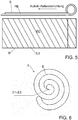
- FIG. 6 shows a view of a rolled-up band B to form a mixing element 3 according to an embodiment of the invention.
- two open ends E1 and E2 of the band B are arranged substantially centrally within the rolled-up band B, so that the mixing element 3 has an asymmetrical edge region.
- the mixing element 3 ensures a substantially homogeneous flow profile over a large part of the pipe cross-section D, an inhomogeneous flow profile can be present in the edge region of the mixing element 3 and thus in the edge region of the pipe cross-section D.
- FIG. 7 shows a view of a rolled-up band B to form a mixing element 3 according to an embodiment of the invention.
- two open ends E1 and E2 of the band B are arranged on outer sides of the rolled-up band B, namely by 180.degree. offset relative to one another, so that the mixing element 3 has a symmetrical edge region, which increases the homogeneity of the flow profile over the pipeline cross section D contributes.
- FIG. 8 schematically illustrates the operating principle of a mixing element 3 according to an embodiment of the invention.
- FIG. 8 illustrates that the mixing element 3 is used for mixing of the gas, so that an inhomogeneous flow profile S1 upstream of the mixing element 3 in an at least largely homogeneous flow profile S2 is converted.
- the mixing element 3 is preferably designed as a swirling device, so that the mixing of the gas and the homogenization by means of a swirling of the gas takes place on wire sections of the wire structure.
- the gas is deflected within the mixing element 3 in all three spatial directions, which contributes to an effective homogenization of the flow profile.
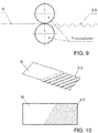
- FIG. 9 illustrates a method for producing an embossing 3.3 on a belt B for a mixing element 3 according to an embodiment of the invention.
- the band B is conveyed to produce the embossing 3.3 by two embossing rollers.
- the wire structure so in particular the fabric is usually produced in a circular knitting process as a hose.
- the tube is flattened at the exit from the knitting machine to a band B. If a flat knitting method is used as an alternative, this step is omitted and the knit is immediately present as a flat band B.
- This band B now passes through two embossing rollers, on the surfaces of which an embossed structure is applied, for. B. an oblique, V-shaped or W-shaped wave structure.
- the band B is characterized z.
- FIG. 10 shows a perspective view above and below a plan view of a band B for a mixing element 3, wherein the band B has a beveled embossing 3.3.
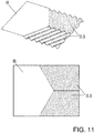
- FIG. 11 shows a perspective view above and below a plan view of a band B for a mixing element 3, wherein the band B has a V-embossing 3.3.
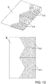
- FIG. 12 shows a perspective view above and below a plan view of a band B for a mixing element 3, wherein the band B has a W-embossing 3.3.
- a W-embossing 3.3 thus preferably comprises at least two V-embossments.
- a quasi-ideal homogeneous flow distribution in front of the gas measuring device can be achieved by the invention. Due to the homogenization caused vortexes can be largely eliminated by the arrangement to the gas measuring device. As a result, a highly accurate detection of the gas mass is possible substantially without disturbing influences.
- the pressure loss caused by the mixing element is relatively low compared to the pressure loss of the entire intake system.
- the properties of the mixing element are mainly determined by the geometric dimensions, wire thickness, wire density, type of winding, number of stitches of the fabric or pitch of the fabric, embossing and embossing depth, and length of the mixing element. By means of one or more of these parameters, the pressure loss and the intensity of the mixing can be adapted to the gas mass flow.
Landscapes
- Engineering & Computer Science (AREA)
- Mechanical Engineering (AREA)
- General Engineering & Computer Science (AREA)
- Chemical & Material Sciences (AREA)
- Physics & Mathematics (AREA)
- Fluid Mechanics (AREA)
- Combustion & Propulsion (AREA)
- General Physics & Mathematics (AREA)
- Ceramic Engineering (AREA)
- Analytical Chemistry (AREA)
- Measuring Volume Flow (AREA)
- Rigid Pipes And Flexible Pipes (AREA)
Description
- Die Erfindung betrifft eine Rohrleitung zur Zuführung eines Gases, insbesondere Luft, an einen Verbrennungsmotor, mit einem einen Durchlass für das Gas bildenden Rohrleitungsquerschnitt und einer Gasmesseinrichtung (vorzugsweise Gasmassenmesseinrichtung) zum Messen eines Gasmassenstromes.
-
US 5,918,279 A offenbart eine Vorrichtung zur Messung der Masse eines strömenden Mediums, mit einem Messelement und einem stromaufwärts des Messelements vorgesehenen Gitter, das eine Vielzahl von Strömungsöffnungen aufweist, wobei die Strömungsöffnungen zumindest bereichsweise einen unterschiedlichen Durchströmquerschnitt aufweisen und die Durchströmquerschnitte der Strömungsöffnungen derart an die Zuströmung zum Gitter angepasst sind, dass stromabwärts des Gitters eine Strömung mit im wesentlichen gleichmässiger Geschwindigkeitsverteilung vorliegt. Ferner kann zum Stand der dieUS 2010/269583 A1 genannt werden. - Um aktuelle Abgasnormen bei Verbrennungskraftmaschinen (Verbrennungsmotoren) einzuhalten, muss die den Verbrennungsmotoren zugeführte Luftmasse möglichst exakt erfasst werden. Hierzu werden vorwiegend Luftmassenmesser in Rohrleitungen verwendet, die nach dem Hitzdraht- bzw. Heißfilmprinzip arbeiten. Dabei wird die Strömungsgeschwindigkeit der Luft üblicherweise nur punktuell im Rohrleitungsquerschnitt gemessen. Bei seltener verwendeten Ultraschallsensoren erfolgt die Messung meist entlang einer Linie im Rohrleitungsquerschnitt. Da nur in einem sehr geringen Bereich des Rohrleitungsquerschnitts gemessen wird, sind die Messergebnisse stark von dem im Rohrleitungsquerschnitt vorliegenden Strömungsprofil abhängig. Das Strömungsprofil ist aber üblicherweise ungleichmäßig/inhomogen, z. B. verursacht durch Störeinflüsse wie gekrümmte Rohrleitungsabschnitte, Einbautoleranzen, Alterung und Verformung von Bauteilen etc.
- Über eine im Motorsteuergerät hinterlegte Kennlinie kann zwar ein kleiner Teil bestimmter Störeinflüsse auf die Strömungsverteilung korrigiert werden (z. B. Rohrverlauf, Querschnittsänderungen vor dem Luftmassenmesser; Aufbau eines Luftfilters etc.). Ein großer Teil bestimmter Störeinflüsse kann jedoch nicht korrigiert werden, z. B. Störeinflüsse, die durch Einbautoleranzen, Alterung und Verformung von Bauteilen, Einflüsse durch die Luftentnahme für die Druckluftversorgung bei Nutzfahrzeugen, Verwendung nicht freigegebener Luftfilter etc. verursacht werden.
- Aus der
WO 2014/088487 A1 ist bekannt, durch eine gezielte Änderung der Querschnittsgeometrie der Rohrleitung eine Verbesserung bestimmter Störeinflüsse zu erreichen. Um aktuelle Abgasnormen einhalten zu können, sind die hierduch erzielbaren Verbesserungen jedoch nicht ausreichend. Aus dem Stand der Technik, z. B. aus derDE10027831A1 , sind ferner Gleichrichtergitter zur Erzielung einer laminaren Luftströmung bekannt. Derartige Gleichrichtergitter dienen also vor allem zur Beseitigung von Wirbeln, so dass eine turbulente in eine laminarere Luftströmung umgewandelt wird, allerdings keine wesentliche Einwirkung auf das Strömungsprofil stattfindet. - Eine Aufgabe der Erfindung ist es, die Genauigkeit der Messung eines Gasmassenstromes in einer Rohrleitung zur Zuführung eines Gases an einen Verbrennungsmotor zu erhöhen.
- Diese Aufgabe kann mit den Merkmalen des unabhängigen Anspruchs gelöst werden. Vorteilhafte Weiterbildungen der Erfindung können den Unteransprüchen und der folgenden Beschreibung entnommen werden.
- Die Erfindung betrifft eine z. B. im Wesentlichen starre oder flexible Rohrleitung zur Zuführung eines Gases (insbesondere Luft) an einen Verbrennungsmotor vorzugsweise eines Kraftfahrzeugs, insbesondere eines Nutzfahrzeugs (z. B. Omnibus oder Lastkraftwagen).
- Die Rohrleitung umfasst einen einen Durchlass für das Gas bildenden Rohrleitungsquerschnitt und eine Gasmesseinrichtung (z. B. Gasmassenmesseinrichtung) zum Messen eines Gasmassenstromes (z. B. ein Gasmassensensor, eine nach dem Hitzdraht- oder Heißfilmprinzip arbeitende Messeinrichtung oder zumindest ein Ultraschallsensor etc.).
- Die Gasmesseinrichtung dient zweckmäßig zum Messen des Gasmassenstroms und zwar insbesondere zum Messen der Strömungsgeschwindigkeit des Gasmassenstroms. Die Erfindung zeichnet sich insbesondere dadurch aus, dass die Rohrleitung ein Mischelement aus einer Drahtstruktur stromaufwärts der Gasmesseinrichtung umfasst und das Mischelement zur Beeinflussung, vorzugsweise zur Durchmischung, des Gases dient, um ein stromaufwärts des Mischelements vorhandenes inhomogenes (Gas-) Strömungsprofil zu homogenisieren, also vorzugsweise die Inhomogenität zumindest reduziert oder vorzugsweise im Wesentlichen vollständig eliminiert werden kann.
- Dadurch kann zweckmäßig ein inhomogenes Strömungsprofil stromaufwärts des Mischelements in ein zumindest im Wesentlichen homogenes Strömungsprofil umgewandelt werden.
- Das Mischelement kann das inhomogene Strömungsprofil vorzugsweise so homogenisieren, dass es in eine z. B. über zumindest den Großteil des Rohrleitungsquerschnitts zweckmäßig im Wesentlichen homogenes Strömungsprofil umgewandelt wird.
- Das Mischelement wirkt also insbesondere so, dass Ungleichverteilungen im Strömungsprofil über den Rohrleitungsquerschnitt durch eine (vorzugsweise im Wesentlichen vollständige) Durchmischung des Gasstroms zumindest reduziert werden, so dass nach dem Durchströmen des Gases durch das Mischelement ein möglichst homogenes Strömungsprofil (über den vorzugsweise im Wesentlichen gesamten Rohrleitungsquerschnitt) vorliegt.
- Die Erzielung eines möglichst homogenen Strömungsprofils kann insbesondere durch eine gezielt herbeigeführte Verwirbelung des Gases an Drahtabschnitten der Drahtstruktur erreicht werden.
- Es ist möglich, dass die Drahtstruktur zumindest ein Drahtgestrick oder zumindest ein Drahtgewebe umfasst.
- Zur Ausbildung des Mischelements umfasst die Drahtstruktur ein aufgerolltes Band aus Drahtgestrick oder Drahtgewebe. Somit kann also ein aufgerolltes Band aus Drahtgestrick oder Drahtgewebe zur Ausbildung des Mischelements dienen. Alternativ oder ergänzend umfasst das Drahtgestrick einen Drahtgestrick-Schlauch. Der Drahtgestrick-Schlauch wird zu einem Band flach gedrückt und das Band wird aufgerollt, um so das Mischelement auszubilden.
- Das Band kann z. B. einen Gestrick- oder Gewebestreifen umfassen und/oder eine z. B. im Wesentlichen horizontal ausgerichtete und/oder im Wesentlichen ebene Ursprungsform aufweisen.
- Es ist möglich, dass auf das Band eine vorzugsweise lineare Prägung aufgebracht ist und die Prägung z. B. relativ zur Rollebene des Bands schräg und/oder nicht senkrecht ausgerichtet ist. Eine z. B. senkrecht zur Rollebene des Bands ausgerichtete Prägung ist nachteilhaft, da beim Aufrollen des Bands Prägeerhöhungen ineinander fallen können.
- Die Prägung kann z. B. ein im Wesentlichen Schräg-Muster, V-Muster (insbesondere Pfeil-Muster) oder im Wesentlichen W-Muster ausbilden, insbesondere zur Erhöhung der Stabilität bei z. B. breiten Bändern.
- Die Prägung ist vorzugsweise als Prägewellung ausgeführt.
- Zur Erzielung einer möglichst gleichmäßigen Durchmischung des Gases kann das Mischelement z. B. eine im Wesentlichen gleichmäßige Dichte und/oder eine im Wesentlichen homogene Struktur aufweisen.
- Das Band kann hierzu z. B. im Gegenschlag aufgerollt sein, zweckmäßig so, dass zumindest zwei übereinander angeordnete Lagen des Bands zweckmäßig von einem Bandende aus gemeinsam aufgerollt sind.
- Das Band kann im aufgerollten Zustand z. B. einzelne Lagen bilden und es ist z. B. möglich, dass die einzelnen Lagen Prägungen vorzugsweise mit unterschiedlicher und/oder entgegengesetzter Ausrichtung aufweisen.
- Bei einem Aufrollen des Bands im Gegenschlag wird das Band zuerst auf vorzugsweise ungefähr halber Länge zumindest einmal zurückgeschlagen und daraufhin die zumindest zwei Lagen gemeinsam aufgerollt. Somit können Prägeerhöhungen einzelner aufgerollter Lagen des Bands eine unterschiedliche, insbesondere entgegengesetzte, Ausrichtung aufweisen und somit zweckmäßig nicht mehr ineinander fallen, wodurch vorzugsweise ein Mischelement mit im Wesentlichen gleichmäßiger Dichte und/oder einer im Wesentlichen homogenen Struktur ausgebildet werden kann.
- Bei einem Aufrollen des Bands im Gleichschlag wird das Band in nur einer Lage von einem Bandende aus aufgerollt, so dass Prägeerhöhungen einzelner aufgerollter Lagen des Bands die gleiche Ausrichtung aufweisen und dadurch ineinander fallen können.
- Es ist möglich, dass im aufgerollten Zustand des Bands zwei offene Enden des Bands an Außenseiten des Bands angeordnet sind, z. B. um 180° +/-40°, +/-30° oder +/-20° versetzt zueinander, so dass z. B. das Mischelement einen im Wesentlichen symmetrischen Randbereich aufweist.
- Es ist allerdings auch möglich, dass im aufgerollten Zustand des Bands zwei offene Enden des Bands (vorzugsweise im Wesentlichen zentral) innerhalb des Bands angeordnet sind, so dass z. B. das Mischelement einen unsymmetrischen Randbereich aufweist.
- Das Mischelement und somit insbesondere die Drahtstruktur kann den im Wesentlichen gesamten Rohrleitungsquerschnitt ausfüllen.
- Es ist möglich, dass das Mischelement als Verwirbelungseinrichtung wirkt, so dass Verwirbelungen des Gases an Drahtabschnitten der Drahtstruktur für die Durchmischung des Gases und die Homogenisierung des inhomogenen Strömungsprofils sorgen.
- Eine Gasströmung am Austritt des Mischelements kann somit z. B. eine Vielzahl an vorzugsweise kleinen Wirbeln aufweisen. Alternativ oder ergänzend kann eine Gasströmung am Austritt des Mischelements stärker verwirbelt sein als am Eintritt des Mischelements. Trotz oder gerade eben wegen der Verwirbelungen kann ein homogenes Strömungsprofil ermöglicht werden.
- Es ist möglich, dass zum Abklingen (insbesondere Reduzieren) der Wirbel stromabwärts des Mischelements eine im Wesentlichen lineare (zweckmäßig gerade) Beruhigungsstrecke für das Gas und/oder zumindest eine Gleichrichtereinrichtung (z. B. ein Gleichrichtergitter) zur Reduzierung der Wirbel und somit zur Erzielung einer im Wesentlichen laminaren Gasströmung ausgebildet ist.
- Eine Gleichrichtereinrichtung zur Reduzierung der Wirbel kann z .B. im oder unmittelbar vor einem Gaseintritt (z. B. Gaseinlass eines Messrohrs) der Gasmesseinrichtung angeordnet sein.
- Es ist möglich, dass Drahtabschnitte des Drahtgestricks in Wirrlage und/oder hintereinander zweckmäßig in einem beliebigen Winkel kreuzend angeordnet sind, so dass vorzugsweise das Gas während der Durchströmung des Mischelements mehrfach umgelenkt wird. Die Umlenkung kann in vorzugsweise allen drei Raumrichtungen erfolgen.
- Es ist möglich, dass Drahtabschnitte zumindest zweier Drahtgewebelagen hintereinander zweckmäßig in einem beliebigen Winkel kreuzend angeordnet sind, so dass vorzugsweise das Gas während der Durchströmung des Mischelements mehrfach umgelenkt wird. Die Umlenkung kann in vorzugsweise allen drei Raumrichtungen erfolgen.
- Die Rohrleitung kann stromaufwärts des Mischelements zumindest eine Störbeaufschlagung aufweisen, wobei die Störbeaufschlagung dazu führt, dass das Gas stromaufwärts des Mischelements ein über den Rohrleitungsquerschnitt inhomogenes/ungleichmäßiges Strömungsprofil aufweist. Alternativ oder ergänzend kann die Rohrleitung stromaufwärts des Mischelements gekrümmt sein und die Krümmung kann dazu führen, dass das Gas stromaufwärts des Mischelements ein über den Rohrleitungsquerschnitt inhomogene/ungleichmäßige Strömungsprofil aufweist.
- Das Mischelement, die Beruhigungsstrecke und/oder zumindest eine Gleichrichtereinrichtung ist vorzugsweise stromaufwärts der Gasmesseinrichtung in der Rohrleitung angeordnet.
- Stromaufwärts des Mischelements kann z. B. ein Gasfilter zum Filtern des Gases angeordnet sein.
- Die Drahtstruktur ist vorzugsweise aus einem Metallmaterial, insbesondere Edelstahl, ausgebildet. Die Drahtstruktur kann im Rahmen der Erfindung aber auch z. B. aus einem Kunststoffmaterial ausgebildet sein.
- Das Drahtgestrick ist zumindest abschnittsweise aus vorzugsweise einem einzigen Draht, insbesondere Metall- und/oder Kunststoffdraht, gestrickt.
- Das Gas ist wie bereits erwähnt vorzugsweise Luft.
- Die Gasmesseinrichtung ist somit vorzugsweise eine Luftmesseinrichtung.
- Die Gasmesseinrichtung dient vorzugsweise zum Messen der (Gas-) Strömungsgeschwindigkeit.
- Im Kontext der Erfindung umfasst das Merkmal "homogenisieren" und/oder "homogen" vorzugsweise Ausführungsformen, bei denen eine Inhomogenität im Wesentlichen vollständig eliminiert wird, aber auch vorzugsweise Ausführungsformen, bei denen eine Inhomogenität nur zweckmäßig wesentlich reduziert wird. Das Merkmal "homogenisieren" und/oder "homogen" ist somit vorzugsweise nicht auf eine vollständige Homogenisierung eines inhomogenen Strömungsprofils eingeschränkt. Auch z. B. ein um die Rohrmittelachse im Wesentlichen rotationssymmetrisches Strömungsprofil kann zweckmäßig im Kontext der Erfindung durch das Merkmal "homogen" und/oder "homogenisieren" umfasst sein.
- Die Erfindung umfasst auch ein Kraftfahrzeug, vorzugsweise ein Nutzfahrzeug (z. B. Omnibus oder Lastkraftwagen) mit einer Rohrleitung nach einem der vorhergehenden Ansprüche.
- Die oben beschriebenen bevorzugten Ausführungsformen und Merkmale der Erfindung sind miteinander kombinierbar. Andere vorteilhafte Weiterbildungen der Erfindung sind in den Unteransprüchen offenbart oder ergeben sich aus der folgenden Beschreibung bevorzugter Ausführungsformen der Erfindung in Verbindung mit den beigefügten Figuren.
- Figur 1
- zeigt eine Ansicht einer Rohrleitung gemäß einer Ausführungsform der Erfindung,
- Figur 2
- zeigt einen Ausschnitt eines Mischelements aus Drahtgestrick gemäß einer Ausführungsform der Erfindung,
- Figur 3
- zeigt einen Ausschnitt eines Drahtgewebes zur Ausbildung eines Mischelements gemäß einer Ausführungsform der Erfindung,
- Figur 4
- zeigt einen Ausschnitt eines Drahtgestricks zur Ausbildung eines Mischelements gemäß einer Ausführungsform der Erfindung,
- Figur 5
- zeigt Ansichten eines Bands zur Ausbildung eines Mischelements gemäß einer Ausführungsform der Erfindung,
- Figur 6
- zeigt eine Ansicht eines aufgerollten Bands zur Ausbildung eines Mischelements gemäß einer Ausführungsform der Erfindung,
- Figur 7
- zeigt eine Ansicht eines aufgerollten Bands zur Ausbildung eines Mischelements gemäß einer anderen Ausführungsform der Erfindung,
- Figur 8
- zeigt schematisch die Wirkweise eines Mischelements gemäß einer Ausführungsform der Erfindung,
- Figur 9
- illustriert ein Verfahren zur Herstellung einer Prägung für ein Mischelement gemäß einer Ausführungsform der Erfindung,
- Figur 10
- zeigt unterschiedliche Ansichten einer Schrägprägung für ein Mischelement gemäß einer Ausführungsform der Erfindung,
- Figur 11
- zeigt unterschiedliche Ansichten einer V-Prägung für ein Mischelement gemäß einer Ausführungsform der Erfindung, und
- Figur 12
- zeigt unterschiedliche Ansichten einer W-Prägung für ein Mischelement gemäß einer Ausführungsform der Erfindung.
- Die in den Figuren gezeigten Ausführungsformen stimmen teilweise überein, so dass identische oder ähnliche Teile mit den gleichen Bezugszeichen versehen sind, wobei zu deren Erläuterung auch auf die Beschreibung der anderen Ausführungsformen verwiesen wird, um Wiederholungen zu vermeiden.
-
Figur 1 zeigt eine Ansicht einer Rohrleitung 1 zur Zuführung eines Gases in Form von Luft an einen nicht gezeigten Verbrennungsmotor gemäß einer Ausführungsform der Erfindung. Die Pfeile P kennzeichnen die Strömungsrichtung des Gases durch die Rohrleitung 1. Der inFigur 1 linke Teil der Rohrleitung 1 bildet ein Reinluftrohr von einem nicht gezeigten Gasfilter, wobei der inFigur 1 rechte Teil der Rohrleitung 1 ein Reinluftrohr zum Verbrennungsmotor bildet. - Die Rohrleitung 1 umfasst einen Durchlass für das Gas bildenden Rohrleitungsquerschnitt D und eine Gasmesseinrichtung 2 zum Messen eines Gasmassenstromes. Die Gasmesseinrichtung 2 arbeitet vorzugsweise nach dem Heißfilm- oder Heizdraht-Prinzip oder aber mit zumindest einem Ultraschallsensor. Auch andere im Stand der Technik bekannte Messeinrichtungen können verwendet werden. Die Gasmesseinrichtung 2 misst die Strömungsgeschwindigkeit zweckmäßig nur punktuell, so dass für eine genaue Messung ein über den Rohrleitungsquerschnitt D möglichst homogenes Strömungsprofil vorteilhaft ist.
- Bezugszeichen S1 kennzeichnet ein Strömungsprofil stromaufwärts eines weiter unten näher beschriebenen Mischelements 3.
Figur 1 zeigt, dass das Strömungsprofil S1 inhomogen und somit ungleichmäßig ist, insbesondere verursacht durch die Krümmung im inFigur 1 linken Teil der Rohrleitung 1. Auch andere Störbeaufschlagungen können zu einem inhomogenen Strömungsprofil S1 führen, z. B. Einbautoleranzen, Alterung und Verformung von Bauteilen, Einflüsse durch Luftentnahme für die Druckluftversorgung bei Nutzfahrzeugen, Verwendung nicht freigegebener Luftfilter etc. Eine Messung der Masse bzw. der Strömungsgeschwindigkeit in einem inhomogenen Strömungsprofil S1 würde zu einem ungenauen Ergebnis führen. - In die Rohrleitung 1 ist deshalb stromaufwärts der Gasmesseinrichtung 2 ein Mischelement 3 mit einem Eintritt 3.1 und einem Austritt 3.2 für das Gas eingebaut. Das Mischelement 3 ist aus einer metallischen oder kunststoffartigen Drahtstruktur ausgebildet und dient zur Durchmischung des Gases, um das stromaufwärts des Mischelements 3 vorhandene inhomogene Strömungsprofil S1 zu homogenisieren, so dass dessen Inhomogenität zumindest reduziert, vorzugsweise im Wesentlichen eliminiert wird. Das Mischelement 3 wirkt dabei so, dass das inhomogene Strömungsprofil S1 in ein über den Rohrleitungsquerschnitt D im Wesentlichen homogenes Strömungsprofil S2 umgewandelt wird.
- Das Mischelement 3 füllt den gesamten Rohrleitungsquerschnitt D aus und fungiert insbesondere als Verwirbelungseinrichtung, so dass die Durchmischung des Gases und somit die Homogenisierung durch Verwirbelung des Gases an Drahtabschnitten der Drahtstruktur erfolgt. Die Gasströmung am Austritt 3.2 des Mischelements 3 weist somit eine Vielzahl an relativ kleinen Wirbeln auf. Es sind sogar Ausführungsformen möglich, bei denen die Gasströmung am Austritt 3.2 des Mischelements 3 stärker verwirbelt ist als am Eintritt 3.1 des Mischelements 3.
- Zum Abklingen der Wirbel stromabwärts des Mischelements 3 umfasst die Rohrleitung 1 eine im Wesentlichen lineare Beruhigungsstrecke 4, innerhalb derer die Wirbel abklingen können. Außerdem umfasst die Rohrleitung 1 zwei optionale Gleichrichtergitter 5.1 und 5.2, die ebenfalls zur Reduzierung der Wirbel stromabwärts des Mischelements 3 dienen. Das Gleichrichtergitter 5.2 ist zweckmäßig im oder unmittelbar vor einem Gaseintritt der Gasmesseinrichtung 2 angeordnet, vorzugsweise in oder unmittelbar vor dessen Messrohr.
- Ziel des Mischelements 3 ist es also, Ungleichverteilungen im Strömungsprofil über den Rohrleitungsquerschnitt D durch eine (z. B. im Wesentlichen vollständige) Durchmischung des Gasstroms zu eliminieren, sodass nach dem Durchströmen des Mischelements 3 ein möglichst homogenes Strömungsprofil S2 über den vorzugsweise im Wesentlichen gesamten Rohrleitungsquerschnitt D vorliegt. Dies kann insbesondere durch eine gezielt herbeigeführte Verwirbelung des Gases an Drahtabschnitten der Drahtstruktur erreicht werden.
- Das Mischelement 3 dient folglich insbesondere zur Homogenisierung eines inhomogenen Strömungsprofils und - im Gegensatz zu aus dem Stand der Technik üblichen Wirbelunterdrückungsvorrichtungen - vorzugsweise nicht dazu, eine turbulente Gasströmung in eine laminarere Gasströmung umzuwandeln.
- Um eine möglichst gleichmäßige Durchmischung des Gases und somit ein möglichst homogenes Strömungsprofil S2 zu ermöglichen, ist das Mischelement 3 mit einer im Wesentlichen gleichmäßigen Dichte und einer im Wesentlichen homogenen Struktur ausgeführt.
- Das Mischelement 3 ist stromaufwärts der Beruhigungsstrecke 4 und der zwei optionalen Gleichrichtergitter 5.1 und 5.2 in der Rohrleitung 1 angeordnet. Das Mischelement 3, die Beruhigungsstrecke 4 und die zwei optionalen Gleichrichtergitter 5.1 und 5.2 sind stromaufwärts der Gasmesseinrichtung 2 in der Rohrleitung 1 angeordnet.
-
Figur 2 zeigt einen Ausschnitt eines Mischelements 3 aus Drahtgestrick gemäß einer Ausführungsform der Erfindung. - Aus
Figur 2 wird ersichtlich, dass Drahtabschnitte des Drahtgestricks in Wirrlage und hintereinander kreuzend angeordnet sind, so dass das Gas während der Durchströmung des Mischelements 3 mehrfach, vorzugsweise in allen drei Raumrichtungen, umgelenkt und somit effektiv verwirbelt und/oder durchmischt werden kann, was inFigur 2 schematisch durch die Pfeile innerhalb des Mischelements 3 angedeutet ist. -
Figur 3 zeigt einen Ausschnitt eines Drahtgewebes zur Ausbildung eines Mischelements 3 gemäß einer Ausführungsform der Erfindung. - Zumindest zwei derartige Drahtgewebe können z. B. hintereinander angeordnet werden, so dass deren Drahtabschnitte sich kreuzen, wodurch das Gas während der Durchströmung des Mischelements 3 mehrfach umgelenkt und somit effektiv verwirbelt und/oder durchmischt und homogenisiert werden kann.
-
Figur 4 zeigt einen Ausschnitt eines Drahtgestricks zur Ausbildung eines Mischelements 3 gemäß einer Ausführungsform der Erfindung. Das Drahtgestrick ist zumindest abschnittsweise aus einem einzigen (Metall- oder Kunststoff-) Draht gestrickt. -
Figur 5 zeigt Ansichten eines Bands B zur Ausbildung eines Mischelements 3 gemäß einer Ausführungsform der Erfindung, wobei inFigur 5 oben eine Seitenansicht und inFigur 5 unten eine zugehörige Draufsicht des Bands B dargestellt ist. Das Band B kann zweckmäßig aus Drahtgewebe, wie z. B. inFigur 3 gezeigt, oder aus Drahtgestrick, wie z. B. inFigur 4 gezeigt, ausgebildet sein. - Das Mischelement 3 kann insbesondere durch Aufrollen (Aufwickeln) des Bands B hergestellt werden.
- Auf das Band B ist eine Prägung 3.3 aufgebracht, die relativ zur Rollebene RE des Bands B schräg und/oder nicht senkrecht ausgerichtet ist. Die Prägung 3.3 sollte nicht senkrecht zur Rollebene RE ausgerichtet sein, weil ansonsten beim Aufrollen des Bands B Prägeerhöhungen nachteilig ineinander fallen können.
-
Figur 5 illustriert ein Aufrollen des Bands B im Gegenschlag, so dass zumindest zwei übereinander gelegte Lagen des Bands B gemeinsam aufgerollt werden. Bei der Ausbildung des Mischelements 3 im Gegenschlag wird das Band B insbesondere auf zweckmäßig ungefähr halber Länge zurückgeschlagen, wobei die daraus resultierenden Lagen dann gemeinsam aufgerollt werden. - Im aufgerollten Zustand weist das Band B und somit das Mischelement 3 einzelne Lagen auf, wobei die einzelnen Lagen Prägungen 3.3 mit unterschiedlicher, insbesondere entgegengesetzter Ausrichtung aufweisen können. Dadurch können Prägeerhöhungen nicht mehr ineinander fallen, was zu einer im Wesentlichen gleichmäßigen Dichte und einer im Wesentlichen homogenen Struktur des Mischelements 3 beiträgt.
- Für eine erhöhte Stabilität bei insbesondere relativ breiten Bändern B kann die Prägung 3.3 auch andere Muster aufweisen, z. B. im Wesentlichen V-förmig (insbesondere Pfeil-förmig) oder W-förmig ausgeführt sein.
- Bei einem Aufwickeln im Gleichschlag wird das Band B hingegen einlagig von einem Ende her aufgerollt. Prägungen 3.3 einzelner Lagen weisen dann die gleiche Ausrichtung auf. Prägeerhöhungen können somit nachteilig ineinander fallen.
- Ein Mischelement 3 aus Drahtgestrick kann insbesondere wie folgt ausgebildet werden: Das Drahtgestrick wird in Form eines Drahtgestrick-Schlauchs zur Verfügung gestellt. Der Drahtgestrick-Schlauch wird zunächst zu einem Band B flach gedrückt und geprägt, woraufhin das Band B z. B. nach dem in
Figur 5 gezeigten Prinzip zur Ausbildung des Mischelements 3 aufgerollt werden kann. -
Figur 6 zeigt eine Ansicht eines aufgerollten Bands B zur Ausbildung eines Mischelements 3 gemäß einer Ausführungsform der Erfindung. - Bei der in
Figur 6 gezeigten Ausführungsform sind zwei offene Enden E1 und E2 des Bands B im Wesentlichen zentral innerhalb des aufgerollten Bands B angeordnet, so dass das Mischelement 3 einen unsymmetrischen Randbereich aufweist. Obwohl das Mischelement 3 für ein im Wesentlichen homogenes Strömungsprofil über einen Großteil des Rohrleitungsquerschnitts D sorgt, kann im Randbereich des Mischelements 3 und somit im Randbereich des Rohrleitungsquerschnitts D ein inhomogenes Strömungsprofil vorliegen. -
Figur 7 zeigt eine Ansicht eines aufgerollten Bands B zur Ausbildung eines Mischelements 3 gemäß einer Ausführungsform der Erfindung. - Bei der in
Figur 7 gezeigten Ausführungsform sind zwei offene Enden E1 und E2 des Bands B an Außenseiten des aufgerollten Bands B angeordnet und zwar um im Wesentlichen 180° versetzt zueinander, so dass das Mischelement 3 einen symmetrischen Randbereich aufweist, was zu einer Erhöhung der Homogenität des Strömungsprofils über den Rohrleitungsquerschnitt D beiträgt. -
Figur 8 illustriert schematisch das Wirkprinzip eines Mischelements 3 gemäß einer Ausführungsform der Erfindung. -
Figur 8 veranschaulicht, dass das Mischelement 3 zur Durchmischung des Gases dient, so dass ein inhomogenes Strömungsprofil S1 stromaufwärts des Mischelements 3 in ein zumindest großteils homogenes Strömungsprofil S2 umgewandelt wird. Zu diesem Zweck ist das Mischelement 3 vorzugsweise als Verwirbelungseinrichtung ausgeführt, so dass die Durchmischung des Gases und die Homogenisierung mittels einer Verwirbelung des Gases an Drahtabschnitten der Drahtstruktur erfolgt. Insbesondere wird das Gas innerhalb des Mischelements 3 in allen drei Raumrichtungen umgelenkt, was zu einer effektiven Homogenisierung des Strömungsprofils beiträgt. -
Figur 9 illustriert ein Verfahren zur Herstellung einer Prägung 3.3 auf ein Band B für ein Mischelement 3 gemäß einer Ausführungsform der Erfindung. Das Band B wird zur Herstellung der Prägung 3.3 durch zwei Prägewalzen befördert. - Die Drahtstruktur, also insbesondere das Gestrick, wird zumeist im Rundstrickverfahren als Schlauch erzeugt. Der Schlauch wird beim Austritt aus der Strickmaschine zu einem Band B flach gedrückt. Wird alternativ ein Flachstrickverfahren verwendet, entfällt dieser Schritt und das Gestrick liegt sofort als flaches Band B vor. Dieses Band B läuft nun durch zwei Prägewalzen, auf deren Oberflächen eine Prägestruktur aufgebracht ist, z. B. eine schräge, V- oder W-förmige Wellenstruktur. Dem Band B wird dadurch z. B. eine schräge, V- oder W-förmige Prägung 3.3 (Wellung) eingeprägt. Durch den Abstand der Prägewalzen zueinander kann die Tiefe der Prägung 3.3 eingestellt werden.
-
Figur 10 zeigt oben eine perspektivische Ansicht und unten eine Draufsicht auf ein Band B für ein Mischelement 3, wobei das Band B eine Schräg-Prägung 3.3 aufweist. -
Figur 11 zeigt oben eine perspektivische Ansicht und unten eine Draufsicht auf ein Band B für ein Mischelement 3, wobei das Band B eine V-Prägung 3.3 aufweist. -
Figur 12 zeigt oben eine perspektivische Ansicht und unten eine Draufsicht auf ein Band B für ein Mischelement 3, wobei das Band B eine W-Prägung 3.3 aufweist. Eine W-Prägung 3.3 umfasst somit vorzugsweise zumindest zwei V-Prägungen. - Durch die Erfindung kann insbesondere eine quasi ideale homogene Strömungsverteilung vor der Gasmesseinrichtung erzielt werden. Durch die Homogenisierung hervorgerufene Wirbel können durch die Anordnung bis zur Gasmesseinrichtung weitestgehend beseitigt werden. Hierdurch ist eine hochgenaue Erfassung der Gasmasse im Wesentlichen ohne störende Einflüsse möglich.
- Der durch das Mischelement verursachte Druckverlust ist im Vergleich zum Druckverlust der gesamten Ansauganlage relativ gering.
- Durch die einfache Integration des Mischelements in die Rohrleitung können bereits vorhandene Ausführungen von Ansauganlagen leicht um eine Gasmassenmesseinrichtung erweitert werden.
- Die Eigenschaften des Mischelements werden vor allem bestimmt durch die geometrischen Abmessungen, Drahtstärke, Drahtdichte, Wicklungsart, Maschenanzahl des Gestricks oder Rastermaß des Gewebes, Prägeart und Prägetiefe, sowie Länge des Mischelements. Über einen oder mehrere dieser Parameter können Druckverlust und Stärke der Durchmischung dem Gasmassenstrom angepasst werden.
- Die Erfindung ist nicht auf die vorstehend beschriebenen bevorzugten Ausführungsbeispiele beschränkt. Vielmehr ist eine Vielzahl von Varianten und Abwandlungen möglich, die ebenfalls von dem Erfindungsgedanken Gebrauch machen und deshalb in den Schutzbereich fallen. Insbesondere beansprucht die Erfindung auch Schutz für den Gegenstand und die Merkmale der Unteransprüche unabhängig von den jeweils in Bezug genommenen Ansprüchen und insbesondere auch ohne die Merkmale des Hauptanspruchs. Die Erfindung umfasst also verschiedene Erfindungsaspekte, die unabhängig voneinander Schutz genießen.
-
- 1
- Rohrleitung
- 2
- Gasmesseinrichtung, insbesondere Luftmesseinrichtung
- 3
- Mischelement
- 3.1
- Eintritt
- 3.2
- Austritt
- 3.3
- Prägung
- D
- Rohrleitungsquerschnitt
- B
- Band zur Ausbildung des Mischelements
- E1
- Offenes Ende des Bands
- E2
- Offenes Ende des Bands
- RE
- Rollebene
- 4
- Beruhigungsstrecke
- 5.1
- Gleichrichtereinrichtung zur Wirbelreduzierung
- 5.2
- Gleichrichtereinrichtung zur Wirbelreduzierung
- S1
- Inhomogene Gasmassenverteilung
- S2
- Homogene Gasmassenverteilung
- P
- Strömungsrichtung des Gases
Claims (18)
- Rohrleitung (1) zur Zuführung eines Gases an einen Verbrennungsmotor, mit einem einen Durchlass für das Gas bildenden Rohrleitungsquerschnitt (D) und einer Gasmesseinrichtung (2) zum Messen eines Gasmassenstromes, wobei die Rohrleitung (1) ein Mischelement (3) aus einer Drahtstruktur stromaufwärts der Gasmesseinrichtung (2) umfasst und das Mischelement (3), zur Beeinflussung, vorzugsweise zur Durchmischung, des Gases dient, um ein stromaufwärts des Mischelements (3) vorhandenes inhomogenes Strömungsprofil (S1) zu homogenisieren, dadurch gekennzeichnet, dass zur Ausbildung des Mischelements (3) die Drahtstruktur ein aufgerolltes Band (B) aus Drahtgestrick oder Drahtgewebe umfasst und/oder ein Drahtgestrick-Schlauch zu einem Band (B) flach gedrückt ist und das Band (B) aufgerollt ist, um das Mischelement (3) auszubilden.
- Rohrleitung (1) nach Anspruch 1, dadurch gekennzeichnet, dass das Mischelement (3) das inhomogene Strömungsprofil (S1) so homogenisiert, dass es in ein über den Rohrleitungsquerschnitt (D) im Wesentlichen homogenes Strömungsprofil (S2) umgewandelt wird.
- Rohrleitung (1) nach Anspruch 1 oder 2, dadurch gekennzeichnet, dass die Drahtstruktur zumindest ein Drahtgestrick oder zumindest ein Drahtgewebe umfasst.
- Rohrleitung (1) nach einem der vorhergehenden Ansprüche, dadurch gekennzeichnet, dass auf das Band (B) eine Prägung (3.3) aufgebracht ist und vorzugsweise die Prägung (3.3) relativ zur Rollebene (RE) des Bands (B) schräg und/oder nicht senkrecht ausgerichtet ist.
- Rohrleitung (1) nach Anspruch 4, dadurch gekennzeichnet, dass die Prägung (3.3) als Prägewellung ausgebildet ist und/oder ein Schräg-, V- oder W-Muster ausbildet.
- Rohrleitung (1) nach einem der vorhergehenden Ansprüche, dadurch gekennzeichnet, dass das Mischelement (3) eine gleichmäßige Dichte und/oder eine homogene Struktur aufweist.
- Rohrleitung (1) nach einem der vorhergehenden Ansprüche, dadurch gekennzeichnet, dass das Band (B) im Gegenschlag aufgerollt ist, vorzugsweise so, dass zumindest zwei übereinander angeordnete Lagen des Bands (B) gemeinsam aufgerollt sind.
- Rohrleitung (1) nach einem der vorhergehenden Ansprüche, dadurch gekennzeichnet, dass das Band (B) im aufgerollten Zustand einzelne Lagen bildet und die einzelnen Lagen unterschiedlich und/oder entgegengesetzt ausgerichtete Prägungen (3.3) aufweisen.
- Rohrleitung (1) nach einem der vorhergehenden Ansprüche, dadurch gekennzeichnet, dass im aufgerollten Zustand des Bands (B)- zwei offene Enden (E1, E2) des Bands (B) an Außenseiten des Bands (B) angeordnet sind, vorzugsweise um 180° +/-40°, +/-30° oder +/-20° versetzt zueinander, oder- zwei offene Enden (E1, E2) des Bands (B) vorzugsweise zentral innerhalb des Bands (B) angeordnet sind.
- Rohrleitung (1) nach einem der vorhergehenden Ansprüche, dadurch gekennzeichnet, dass das Mischelement (3) den gesamten Rohrleitungsquerschnitt (D) ausfüllt.
- Rohrleitung (1) nach einem der vorhergehenden Ansprüche, dadurch gekennzeichnet, dass das Mischelement (3) als Verwirbelungseinrichtung wirkt, so dass Verwirbelungen des Gases an Drahtabschnitten der Drahtstruktur für die Durchmischung des Gases und die Homogenisierung des inhomogenen Strömungsprofils (S1) sorgen.
- Rohrleitung (1) nach einem der vorhergehenden Ansprüche, dadurch gekennzeichnet, dass eine Gasströmung am Austritt (3.2) des Mischelements (3) eine Vielzahl an Wirbeln aufweist und/oder eine Gasströmung am Austritt (3.2) des Mischelements (3) stärker verwirbelt ist als am Eintritt (3.1) des Mischelements (3) und zum Abklingen der durch das Mischelement (3) erzeugten Wirbel stromabwärts des Mischelements (3) eine lineare Beruhigungsstrecke (4) und/oder zumindest eine Gleichrichtereinrichtung (5.1, 5.2) zur Reduzierung der Wirbel ausgebildet ist.
- Rohrleitung (1) nach einem der vorhergehenden Ansprüche, dadurch gekennzeichnet, dass eine Gleichrichtereinrichtung (5.2) zur Reduzierung von Wirbeln im oder unmittelbar vor einem Gaseintritt der Gasmesseinrichtung (2) angeordnet ist.
- Rohrleitung (1) nach einem der vorhergehenden Ansprüche, dadurch gekennzeichnet, dass- Drahtabschnitte des Drahtgestricks in Wirrlage und/oder hintereinander kreuzend angeordnet sind, so dass vorzugsweise das Gas während der Durchströmung des Mischelements (3) mehrfach umgelenkt wird, oder- Drahtabschnitte zumindest zweier Drahtgewebelagen hintereinander kreuzend angeordnet sind, so dass vorzugsweise das Gas während der Durchströmung des Mischelements (3) mehrfach umgelenkt wird.
- Rohrleitung (1) nach einem der vorhergehenden Ansprüche, dadurch gekennzeichnet, dass die Rohrleitung (1) stromaufwärts des Mischelements (3)- eine Störbeaufschlagung aufweist und die Störbeaufschlagung dazu führt, dass das Gas stromaufwärts des Mischelements (3) ein über den Rohrleitungsquerschnitt (D) inhomogenes Strömungsprofil (S1) aufweist, oder- gekrümmt ist, so dass das Gas stromaufwärts des Mischelements (3) ein über den Rohrleitungsquerschnitt (D) inhomogenes Strömungsprofil (S1) aufweist.
- Rohrleitung (1) nach einem der vorhergehenden Ansprüche, dadurch gekennzeichnet, dass das Mischelement (3), die Beruhigungsstrecke (4) und/oder zumindest eine Gleichrichtereinrichtung (5.1, 5.2) stromaufwärts der Gasmesseinrichtung (4) in der Rohrleitung (1) angeordnet ist.
- Rohrleitung (1) nach einem der vorhergehenden Ansprüche, dadurch gekennzeichnet, dass- die Drahtstruktur aus einem Metall- oder Kunststoffmaterial, insbesondere Edelstahl, ausgebildet ist, und/oder- das Drahtgestrick zumindest abschnittsweise aus einem einzigen Draht gestrickt ist.
- Kraftfahrzeug, vorzugsweise Nutzfahrzeug, mit einer Rohrleitung (1) nach einem der vorhergehenden Ansprüche.
Applications Claiming Priority (1)
| Application Number | Priority Date | Filing Date | Title |
|---|---|---|---|
| DE102017002086.8A DE102017002086A1 (de) | 2017-03-03 | 2017-03-03 | Kraftfahrzeug-Rohrleitung mit einem Mischelement aus einer Drahtstruktur |
Publications (2)
| Publication Number | Publication Date |
|---|---|
| EP3370039A1 EP3370039A1 (de) | 2018-09-05 |
| EP3370039B1 true EP3370039B1 (de) | 2019-09-04 |
Family
ID=61283085
Family Applications (1)
| Application Number | Title | Priority Date | Filing Date |
|---|---|---|---|
| EP18158638.9A Active EP3370039B1 (de) | 2017-03-03 | 2018-02-26 | Kraftfahrzeug-rohrleitung mit einem mischelement aus einer drahtstruktur |
Country Status (7)
| Country | Link |
|---|---|
| US (1) | US11053895B2 (de) |
| EP (1) | EP3370039B1 (de) |
| JP (1) | JP7049139B2 (de) |
| CN (1) | CN108843459A (de) |
| BR (1) | BR102018004298B1 (de) |
| DE (1) | DE102017002086A1 (de) |
| RU (1) | RU2757085C2 (de) |
Families Citing this family (1)
| Publication number | Priority date | Publication date | Assignee | Title |
|---|---|---|---|---|
| CN116624296B (zh) * | 2023-06-07 | 2025-03-25 | 江铃汽车股份有限公司 | 一种轻卡柴油发动机进气系统、发动机及汽车 |
Family Cites Families (41)
| Publication number | Priority date | Publication date | Assignee | Title |
|---|---|---|---|---|
| US1490920A (en) * | 1923-02-27 | 1924-04-22 | Ernest R Godward | Vaporizer for volatile-fuel mixtures |
| US1829401A (en) * | 1928-01-09 | 1931-10-27 | Ac Spark Plug Co | Air cleaner |
| US2304689A (en) * | 1939-06-07 | 1942-12-08 | Creamery Package Mfg Co | Homogenizing valve |
| US3349619A (en) * | 1959-07-29 | 1967-10-31 | Meriam Instr Company | Laminar flow element and flow meter |
| US3112262A (en) * | 1960-07-12 | 1963-11-26 | New York Business Dev Corp | Filter unit and filter cartridge therefor |
| US3346302A (en) * | 1964-11-13 | 1967-10-10 | Robintech Inc | Lubricating and load-carrying pad for railway car center bearings and the like |
| FR1586791A (de) * | 1968-10-23 | 1970-02-27 | ||
| GB1285574A (en) * | 1969-04-17 | 1972-08-16 | Atomic Energy Authority Uk | Improvements in or relating to filters |
| US3792609A (en) * | 1971-05-10 | 1974-02-19 | Tylan Corp | Flow splitter |
| US3901311A (en) * | 1973-01-12 | 1975-08-26 | Grumman Aerospace Corp | Self-filling hollow core arterial heat pipe |
| US3960239A (en) * | 1973-08-15 | 1976-06-01 | Barry Wright Corporation | Noise-reducing fluid-flow devices |
| SU664101A1 (ru) | 1977-09-05 | 1979-05-25 | Всесоюзное научно-производственное объединение целлюлозно-бумажной промышленности | Устройство дл спр млени профил скоростей потока жидкости |
| US4457499A (en) * | 1980-01-25 | 1984-07-03 | Metex Corporation | Pile driver cushion |
| US4660587A (en) * | 1986-07-28 | 1987-04-28 | Rizzie Joseph W | System for producing uniform velocity distribution of fluids in conduits |
| JP2511992B2 (ja) | 1987-07-22 | 1996-07-03 | 株式会社日立製作所 | 内燃機関の吸気構造 |
| US4909730A (en) * | 1989-01-23 | 1990-03-20 | Westech Industrial Ltd. | Flame arrester having detonation-attenuating means |
| DE59010035D1 (de) | 1990-05-30 | 1996-02-15 | Siemens Ag | Strömungswandler |
| DE4423329C2 (de) * | 1993-06-28 | 1999-02-25 | Mannesmann Ag | Vorrichtung zur Reinigung schadstoffbeladener Abluft durch heterogene Katalyse |
| JPH08285659A (ja) * | 1995-04-19 | 1996-11-01 | Hitachi Ltd | 空気流量測定装置 |
| US5596969A (en) * | 1995-10-02 | 1997-01-28 | Cummins Engine Company, Inc. | Flow conditioning gas mass sensor |
| DE19647081A1 (de) | 1996-11-14 | 1998-05-28 | Bosch Gmbh Robert | Vorrichtung zur Messung der Masse eines strömenden Mediums |
| JP3477021B2 (ja) * | 1997-03-28 | 2003-12-10 | 三菱電機株式会社 | 内燃機関の吸気装置 |
| DE10027831C2 (de) | 2000-06-05 | 2002-08-01 | Siemens Ag | Massenstrommesser |
| US7416580B2 (en) * | 2001-04-11 | 2008-08-26 | Donaldsom Company, Inc. | Filter assemblies and systems for intake air for fuel cells |
| DE10208872C1 (de) * | 2002-03-01 | 2003-08-07 | Emitec Emissionstechnologie | Verfahren zum Herstellen eines Wabenkörpers, insbesondere für einen Katalysator-Trägerkörper in Abgasreinigungsanlagen von Brennkraftmaschinen, mit einem Flanschstück zur Aufnahme für einen Messfühler und entsprechend hergestellter Wabenkörper |
| US6893485B2 (en) * | 2002-05-31 | 2005-05-17 | Swabey, Ogilvy, Renault | Method and kit for use with standard pipe couplings to construct a de-aerator |
| US7083860B2 (en) * | 2002-08-16 | 2006-08-01 | Emitec Gesellschaft Fuer Emissionstechnologie Mbh | Metallic honeycomb body having at least partially perforated sheet-metal layers |
| CN1395082A (zh) * | 2002-08-23 | 2003-02-05 | 博益(天津)气动技术研究所有限公司 | 气体层流流量传感器 |
| US7025797B2 (en) * | 2002-09-19 | 2006-04-11 | Acs Industries, Inc. | Folded mesh filter for particulates |
| DE10300408A1 (de) * | 2003-01-09 | 2004-07-22 | Emitec Gesellschaft Für Emissionstechnologie Mbh | Verfahren zur Behandlung eines Fluids und Wabenkörper |
| RU2249741C2 (ru) | 2003-02-26 | 2005-04-10 | Андреев Александр Павлович | Клапан регулирующий |
| DE10326381B4 (de) | 2003-06-12 | 2005-09-22 | Jähn, Peter | Turbulenzerzeuger |
| WO2005005932A1 (ja) * | 2003-07-15 | 2005-01-20 | Matsushita Electric Industrial Co., Ltd. | 流れ計測装置 |
| US7185678B1 (en) * | 2003-12-11 | 2007-03-06 | Nitram Energy, Inc. | Orifice plate diffuser |
| RU2315221C1 (ru) | 2006-03-21 | 2008-01-20 | Григорий Юрьевич Панчеха | Дроссельное устройство |
| DE202008010058U1 (de) | 2008-07-25 | 2009-12-03 | Mann+Hummel Gmbh | Luftfiltersystem eines Kraftfahrzeuges |
| US7905153B2 (en) * | 2009-04-24 | 2011-03-15 | Mann+Hummel Gmbh | Flow vortex suppression apparatus for a mass air flow sensor |
| JP2011064278A (ja) * | 2009-09-17 | 2011-03-31 | Yamatake Corp | 整流装置および整流器の取り付け方法 |
| DE102010062892B4 (de) | 2010-12-13 | 2023-07-06 | Robert Bosch Gmbh | Strömungsgitter zum Einsatz in einem Strömungsrohr eines strömenden fluiden Mediums |
| DE102011105441B3 (de) | 2011-06-20 | 2012-07-26 | Mann + Hummel Gmbh | Strömungsgitter und Verfahren zur Herstellung eines Strömungsgitters |
| SE538092C2 (sv) | 2012-12-04 | 2016-03-01 | Scania Cv Ab | Luftmassemätarrör |
-
2017
- 2017-03-03 DE DE102017002086.8A patent/DE102017002086A1/de not_active Withdrawn
-
2018
- 2018-02-26 EP EP18158638.9A patent/EP3370039B1/de active Active
- 2018-02-28 US US15/908,450 patent/US11053895B2/en active Active
- 2018-03-02 BR BR102018004298-0A patent/BR102018004298B1/pt active IP Right Grant
- 2018-03-02 RU RU2018107648A patent/RU2757085C2/ru active
- 2018-03-05 JP JP2018038286A patent/JP7049139B2/ja active Active
- 2018-03-05 CN CN201810178072.3A patent/CN108843459A/zh active Pending
Non-Patent Citations (1)
| Title |
|---|
| None * |
Also Published As
| Publication number | Publication date |
|---|---|
| BR102018004298B1 (pt) | 2023-03-07 |
| RU2757085C2 (ru) | 2021-10-11 |
| RU2018107648A3 (de) | 2021-05-14 |
| DE102017002086A1 (de) | 2018-09-06 |
| JP2018155741A (ja) | 2018-10-04 |
| BR102018004298A2 (pt) | 2018-12-18 |
| US11053895B2 (en) | 2021-07-06 |
| CN108843459A (zh) | 2018-11-20 |
| JP7049139B2 (ja) | 2022-04-06 |
| US20180252187A1 (en) | 2018-09-06 |
| RU2018107648A (ru) | 2019-09-03 |
| EP3370039A1 (de) | 2018-09-05 |
Similar Documents
| Publication | Publication Date | Title |
|---|---|---|
| EP2172657B1 (de) | Strömungsrichter für ein Durchflussmessgerät, insbesondere ein Ultraschallmessgerät | |
| EP2324329B1 (de) | Sensoranordnung zur bestimmung eines parameters eines fluiden mediums | |
| DE2934137A1 (de) | Stroemungsmessanordnung | |
| DE102013009347A1 (de) | Durchflussmesser | |
| EP2508815A1 (de) | Einrichtung zur Beeinflussung einer Luftströmung in einer Komponente einer klimatechnischen Anlage | |
| EP2607718A1 (de) | Strömungsgleichrichter | |
| DE102010062892B4 (de) | Strömungsgitter zum Einsatz in einem Strömungsrohr eines strömenden fluiden Mediums | |
| DE19942501A1 (de) | Vorrichtung zur Messung von zumindest einem Parameter eines in einer Leitung strömenden Mediums | |
| WO2013135678A1 (de) | Anlage zur entnahme von abgasproben von verbrennungskraftmaschinen | |
| EP3370039B1 (de) | Kraftfahrzeug-rohrleitung mit einem mischelement aus einer drahtstruktur | |
| EP2215434B1 (de) | Sensoranordnung zur bestimmung eines parameters eines fluiden mediums | |
| DE102007060046A1 (de) | Sensoranordnung zur Bestimmung eines Parameters eines strömenden fluiden Mediums | |
| DE112017005323T5 (de) | Substratform, Geometrie, Positionierung und/oder Zelldichte zur Verbesserung der Nachbehandlungsleistung | |
| DE19735373C1 (de) | Strömungswandler für einen Luftmasssenmesser | |
| EP4179188B1 (de) | Abgasnachbehandlungsvorrichtung | |
| EP3333484B1 (de) | Brennkammerschindel einer gasturbine | |
| DE102014217844A1 (de) | Abgasbehandlungsanlage für eine Brennkraftmaschine und Brennkraftmaschine | |
| DE112017005335T5 (de) | Luftströmungskonditioniervorrichtung | |
| DE102007023163A1 (de) | Durchflussmesser | |
| DE10205754A1 (de) | Rohr-Luftmassemesser | |
| DE102011051196B4 (de) | Luftmassenmesser | |
| DE19902212A1 (de) | Perforiertes Rohr zum Bau von Schalldämpfern | |
| DE102009030927A1 (de) | Vorrichtung zur selektiven katalytischen NOx-Reduktion in sauerstoffhaltigem Abgas | |
| DE202021104287U1 (de) | Bestimmung des Durchflusses eines strömenden Fluids | |
| DD285155A5 (de) | Stroemungsgleichrichter |
Legal Events
| Date | Code | Title | Description |
|---|---|---|---|
| PUAI | Public reference made under article 153(3) epc to a published international application that has entered the european phase |
Free format text: ORIGINAL CODE: 0009012 |
|
| STAA | Information on the status of an ep patent application or granted ep patent |
Free format text: STATUS: THE APPLICATION HAS BEEN PUBLISHED |
|
| AK | Designated contracting states |
Kind code of ref document: A1 Designated state(s): AL AT BE BG CH CY CZ DE DK EE ES FI FR GB GR HR HU IE IS IT LI LT LU LV MC MK MT NL NO PL PT RO RS SE SI SK SM TR |
|
| AX | Request for extension of the european patent |
Extension state: BA ME |
|
| STAA | Information on the status of an ep patent application or granted ep patent |
Free format text: STATUS: REQUEST FOR EXAMINATION WAS MADE |
|
| 17P | Request for examination filed |
Effective date: 20190107 |
|
| RBV | Designated contracting states (corrected) |
Designated state(s): AL AT BE BG CH CY CZ DE DK EE ES FI FR GB GR HR HU IE IS IT LI LT LU LV MC MK MT NL NO PL PT RO RS SE SI SK SM TR |
|
| GRAP | Despatch of communication of intention to grant a patent |
Free format text: ORIGINAL CODE: EPIDOSNIGR1 |
|
| STAA | Information on the status of an ep patent application or granted ep patent |
Free format text: STATUS: GRANT OF PATENT IS INTENDED |
|
| INTG | Intention to grant announced |
Effective date: 20190328 |
|
| RAP1 | Party data changed (applicant data changed or rights of an application transferred) |
Owner name: MAN TRUCK & BUS SE |
|
| GRAS | Grant fee paid |
Free format text: ORIGINAL CODE: EPIDOSNIGR3 |
|
| GRAA | (expected) grant |
Free format text: ORIGINAL CODE: 0009210 |
|
| STAA | Information on the status of an ep patent application or granted ep patent |
Free format text: STATUS: THE PATENT HAS BEEN GRANTED |
|
| AK | Designated contracting states |
Kind code of ref document: B1 Designated state(s): AL AT BE BG CH CY CZ DE DK EE ES FI FR GB GR HR HU IE IS IT LI LT LU LV MC MK MT NL NO PL PT RO RS SE SI SK SM TR |
|
| REG | Reference to a national code |
Ref country code: GB Ref legal event code: FG4D Free format text: NOT ENGLISH |
|
| REG | Reference to a national code |
Ref country code: CH Ref legal event code: EP |
|
| REG | Reference to a national code |
Ref country code: AT Ref legal event code: REF Ref document number: 1176025 Country of ref document: AT Kind code of ref document: T Effective date: 20190915 |
|
| REG | Reference to a national code |
Ref country code: DE Ref legal event code: R096 Ref document number: 502018000179 Country of ref document: DE |
|
| REG | Reference to a national code |
Ref country code: IE Ref legal event code: FG4D Free format text: LANGUAGE OF EP DOCUMENT: GERMAN |
|
| REG | Reference to a national code |
Ref country code: SE Ref legal event code: TRGR |
|
| REG | Reference to a national code |
Ref country code: NL Ref legal event code: FP |
|
| REG | Reference to a national code |
Ref country code: LT Ref legal event code: MG4D |
|
| PG25 | Lapsed in a contracting state [announced via postgrant information from national office to epo] |
Ref country code: FI Free format text: LAPSE BECAUSE OF FAILURE TO SUBMIT A TRANSLATION OF THE DESCRIPTION OR TO PAY THE FEE WITHIN THE PRESCRIBED TIME-LIMIT Effective date: 20190904 Ref country code: BG Free format text: LAPSE BECAUSE OF FAILURE TO SUBMIT A TRANSLATION OF THE DESCRIPTION OR TO PAY THE FEE WITHIN THE PRESCRIBED TIME-LIMIT Effective date: 20191204 Ref country code: NO Free format text: LAPSE BECAUSE OF FAILURE TO SUBMIT A TRANSLATION OF THE DESCRIPTION OR TO PAY THE FEE WITHIN THE PRESCRIBED TIME-LIMIT Effective date: 20191204 Ref country code: LT Free format text: LAPSE BECAUSE OF FAILURE TO SUBMIT A TRANSLATION OF THE DESCRIPTION OR TO PAY THE FEE WITHIN THE PRESCRIBED TIME-LIMIT Effective date: 20190904 Ref country code: HR Free format text: LAPSE BECAUSE OF FAILURE TO SUBMIT A TRANSLATION OF THE DESCRIPTION OR TO PAY THE FEE WITHIN THE PRESCRIBED TIME-LIMIT Effective date: 20190904 |
|
| PG25 | Lapsed in a contracting state [announced via postgrant information from national office to epo] |
Ref country code: GR Free format text: LAPSE BECAUSE OF FAILURE TO SUBMIT A TRANSLATION OF THE DESCRIPTION OR TO PAY THE FEE WITHIN THE PRESCRIBED TIME-LIMIT Effective date: 20191205 Ref country code: AL Free format text: LAPSE BECAUSE OF FAILURE TO SUBMIT A TRANSLATION OF THE DESCRIPTION OR TO PAY THE FEE WITHIN THE PRESCRIBED TIME-LIMIT Effective date: 20190904 Ref country code: LV Free format text: LAPSE BECAUSE OF FAILURE TO SUBMIT A TRANSLATION OF THE DESCRIPTION OR TO PAY THE FEE WITHIN THE PRESCRIBED TIME-LIMIT Effective date: 20190904 Ref country code: RS Free format text: LAPSE BECAUSE OF FAILURE TO SUBMIT A TRANSLATION OF THE DESCRIPTION OR TO PAY THE FEE WITHIN THE PRESCRIBED TIME-LIMIT Effective date: 20190904 Ref country code: ES Free format text: LAPSE BECAUSE OF FAILURE TO SUBMIT A TRANSLATION OF THE DESCRIPTION OR TO PAY THE FEE WITHIN THE PRESCRIBED TIME-LIMIT Effective date: 20190904 |
|
| PG25 | Lapsed in a contracting state [announced via postgrant information from national office to epo] |
Ref country code: EE Free format text: LAPSE BECAUSE OF FAILURE TO SUBMIT A TRANSLATION OF THE DESCRIPTION OR TO PAY THE FEE WITHIN THE PRESCRIBED TIME-LIMIT Effective date: 20190904 Ref country code: PL Free format text: LAPSE BECAUSE OF FAILURE TO SUBMIT A TRANSLATION OF THE DESCRIPTION OR TO PAY THE FEE WITHIN THE PRESCRIBED TIME-LIMIT Effective date: 20190904 Ref country code: PT Free format text: LAPSE BECAUSE OF FAILURE TO SUBMIT A TRANSLATION OF THE DESCRIPTION OR TO PAY THE FEE WITHIN THE PRESCRIBED TIME-LIMIT Effective date: 20200106 Ref country code: RO Free format text: LAPSE BECAUSE OF FAILURE TO SUBMIT A TRANSLATION OF THE DESCRIPTION OR TO PAY THE FEE WITHIN THE PRESCRIBED TIME-LIMIT Effective date: 20190904 |
|
| PG25 | Lapsed in a contracting state [announced via postgrant information from national office to epo] |
Ref country code: SK Free format text: LAPSE BECAUSE OF FAILURE TO SUBMIT A TRANSLATION OF THE DESCRIPTION OR TO PAY THE FEE WITHIN THE PRESCRIBED TIME-LIMIT Effective date: 20190904 Ref country code: CZ Free format text: LAPSE BECAUSE OF FAILURE TO SUBMIT A TRANSLATION OF THE DESCRIPTION OR TO PAY THE FEE WITHIN THE PRESCRIBED TIME-LIMIT Effective date: 20190904 Ref country code: IS Free format text: LAPSE BECAUSE OF FAILURE TO SUBMIT A TRANSLATION OF THE DESCRIPTION OR TO PAY THE FEE WITHIN THE PRESCRIBED TIME-LIMIT Effective date: 20200224 Ref country code: SM Free format text: LAPSE BECAUSE OF FAILURE TO SUBMIT A TRANSLATION OF THE DESCRIPTION OR TO PAY THE FEE WITHIN THE PRESCRIBED TIME-LIMIT Effective date: 20190904 |
|
| REG | Reference to a national code |
Ref country code: DE Ref legal event code: R097 Ref document number: 502018000179 Country of ref document: DE |
|
| PLBE | No opposition filed within time limit |
Free format text: ORIGINAL CODE: 0009261 |
|
| STAA | Information on the status of an ep patent application or granted ep patent |
Free format text: STATUS: NO OPPOSITION FILED WITHIN TIME LIMIT |
|
| PG2D | Information on lapse in contracting state deleted |
Ref country code: IS |
|
| PG25 | Lapsed in a contracting state [announced via postgrant information from national office to epo] |
Ref country code: DK Free format text: LAPSE BECAUSE OF FAILURE TO SUBMIT A TRANSLATION OF THE DESCRIPTION OR TO PAY THE FEE WITHIN THE PRESCRIBED TIME-LIMIT Effective date: 20190904 Ref country code: IS Free format text: LAPSE BECAUSE OF FAILURE TO SUBMIT A TRANSLATION OF THE DESCRIPTION OR TO PAY THE FEE WITHIN THE PRESCRIBED TIME-LIMIT Effective date: 20200105 |
|
| 26N | No opposition filed |
Effective date: 20200605 |
|
| PG25 | Lapsed in a contracting state [announced via postgrant information from national office to epo] |
Ref country code: SI Free format text: LAPSE BECAUSE OF FAILURE TO SUBMIT A TRANSLATION OF THE DESCRIPTION OR TO PAY THE FEE WITHIN THE PRESCRIBED TIME-LIMIT Effective date: 20190904 |
|
| REG | Reference to a national code |
Ref country code: BE Ref legal event code: MM Effective date: 20200229 |
|
| PG25 | Lapsed in a contracting state [announced via postgrant information from national office to epo] |
Ref country code: LU Free format text: LAPSE BECAUSE OF NON-PAYMENT OF DUE FEES Effective date: 20200226 Ref country code: MC Free format text: LAPSE BECAUSE OF FAILURE TO SUBMIT A TRANSLATION OF THE DESCRIPTION OR TO PAY THE FEE WITHIN THE PRESCRIBED TIME-LIMIT Effective date: 20190904 |
|
| PG25 | Lapsed in a contracting state [announced via postgrant information from national office to epo] |
Ref country code: IE Free format text: LAPSE BECAUSE OF NON-PAYMENT OF DUE FEES Effective date: 20200226 |
|
| PG25 | Lapsed in a contracting state [announced via postgrant information from national office to epo] |
Ref country code: BE Free format text: LAPSE BECAUSE OF NON-PAYMENT OF DUE FEES Effective date: 20200229 |
|
| PG25 | Lapsed in a contracting state [announced via postgrant information from national office to epo] |
Ref country code: CH Free format text: LAPSE BECAUSE OF NON-PAYMENT OF DUE FEES Effective date: 20210228 Ref country code: LI Free format text: LAPSE BECAUSE OF NON-PAYMENT OF DUE FEES Effective date: 20210228 |
|
| PG25 | Lapsed in a contracting state [announced via postgrant information from national office to epo] |
Ref country code: TR Free format text: LAPSE BECAUSE OF FAILURE TO SUBMIT A TRANSLATION OF THE DESCRIPTION OR TO PAY THE FEE WITHIN THE PRESCRIBED TIME-LIMIT Effective date: 20190904 Ref country code: MT Free format text: LAPSE BECAUSE OF FAILURE TO SUBMIT A TRANSLATION OF THE DESCRIPTION OR TO PAY THE FEE WITHIN THE PRESCRIBED TIME-LIMIT Effective date: 20190904 Ref country code: CY Free format text: LAPSE BECAUSE OF FAILURE TO SUBMIT A TRANSLATION OF THE DESCRIPTION OR TO PAY THE FEE WITHIN THE PRESCRIBED TIME-LIMIT Effective date: 20190904 |
|
| PG25 | Lapsed in a contracting state [announced via postgrant information from national office to epo] |
Ref country code: MK Free format text: LAPSE BECAUSE OF FAILURE TO SUBMIT A TRANSLATION OF THE DESCRIPTION OR TO PAY THE FEE WITHIN THE PRESCRIBED TIME-LIMIT Effective date: 20190904 |
|
| GBPC | Gb: european patent ceased through non-payment of renewal fee |
Effective date: 20220226 |
|
| PG25 | Lapsed in a contracting state [announced via postgrant information from national office to epo] |
Ref country code: GB Free format text: LAPSE BECAUSE OF NON-PAYMENT OF DUE FEES Effective date: 20220226 |
|
| REG | Reference to a national code |
Ref country code: AT Ref legal event code: MM01 Ref document number: 1176025 Country of ref document: AT Kind code of ref document: T Effective date: 20230226 |
|
| PG25 | Lapsed in a contracting state [announced via postgrant information from national office to epo] |
Ref country code: AT Free format text: LAPSE BECAUSE OF NON-PAYMENT OF DUE FEES Effective date: 20230226 |
|
| PG25 | Lapsed in a contracting state [announced via postgrant information from national office to epo] |
Ref country code: AT Free format text: LAPSE BECAUSE OF NON-PAYMENT OF DUE FEES Effective date: 20230226 |
|
| PGFP | Annual fee paid to national office [announced via postgrant information from national office to epo] |
Ref country code: NL Payment date: 20250224 Year of fee payment: 8 |
|
| PGFP | Annual fee paid to national office [announced via postgrant information from national office to epo] |
Ref country code: DE Payment date: 20250226 Year of fee payment: 8 |
|
| PGFP | Annual fee paid to national office [announced via postgrant information from national office to epo] |
Ref country code: SE Payment date: 20250224 Year of fee payment: 8 |
|
| PGFP | Annual fee paid to national office [announced via postgrant information from national office to epo] |
Ref country code: FR Payment date: 20250224 Year of fee payment: 8 |
|
| PGFP | Annual fee paid to national office [announced via postgrant information from national office to epo] |
Ref country code: IT Payment date: 20250225 Year of fee payment: 8 |