EP3369496A1 - Horizontale bandgiessanlage mit optimierter kühlung - Google Patents
Horizontale bandgiessanlage mit optimierter kühlung Download PDFInfo
- Publication number
- EP3369496A1 EP3369496A1 EP18158502.7A EP18158502A EP3369496A1 EP 3369496 A1 EP3369496 A1 EP 3369496A1 EP 18158502 A EP18158502 A EP 18158502A EP 3369496 A1 EP3369496 A1 EP 3369496A1
- Authority
- EP
- European Patent Office
- Prior art keywords
- cooling element
- strip
- solidifying
- cooling
- casting
- Prior art date
- Legal status (The legal status is an assumption and is not a legal conclusion. Google has not performed a legal analysis and makes no representation as to the accuracy of the status listed.)
- Granted
Links
Images

Classifications
-
- B—PERFORMING OPERATIONS; TRANSPORTING
- B22—CASTING; POWDER METALLURGY
- B22D—CASTING OF METALS; CASTING OF OTHER SUBSTANCES BY THE SAME PROCESSES OR DEVICES
- B22D11/00—Continuous casting of metals, i.e. casting in indefinite lengths
- B22D11/06—Continuous casting of metals, i.e. casting in indefinite lengths into moulds with travelling walls, e.g. with rolls, plates, belts, caterpillars
- B22D11/0631—Continuous casting of metals, i.e. casting in indefinite lengths into moulds with travelling walls, e.g. with rolls, plates, belts, caterpillars formed by a travelling straight surface, e.g. through-like moulds, a belt
-
- B—PERFORMING OPERATIONS; TRANSPORTING
- B22—CASTING; POWDER METALLURGY
- B22D—CASTING OF METALS; CASTING OF OTHER SUBSTANCES BY THE SAME PROCESSES OR DEVICES
- B22D11/00—Continuous casting of metals, i.e. casting in indefinite lengths
- B22D11/12—Accessories for subsequent treating or working cast stock in situ
- B22D11/124—Accessories for subsequent treating or working cast stock in situ for cooling
- B22D11/1243—Accessories for subsequent treating or working cast stock in situ for cooling by using cooling grids or cooling plates
-
- B—PERFORMING OPERATIONS; TRANSPORTING
- B22—CASTING; POWDER METALLURGY
- B22D—CASTING OF METALS; CASTING OF OTHER SUBSTANCES BY THE SAME PROCESSES OR DEVICES
- B22D11/00—Continuous casting of metals, i.e. casting in indefinite lengths
- B22D11/14—Plants for continuous casting
- B22D11/143—Plants for continuous casting for horizontal casting
Definitions
- the invention relates to a system for horizontal strip casting of a pre-strip of metal.
- the strip casting plant has a melting vessel from which melt is fed via a pouring nozzle onto a horizontally encircling casting belt.
- a cooling device is arranged under an upper run of the casting belt.
- the abandoned melt solidifies to a preliminary band.
- the strip casting plant has an enclosure into which a gas stream is introduced in order to form a reducing or oxidizing atmosphere or an inert gas atmosphere for the discontinued melt and the solidifying pre-strip.
- the gas stream is introduced via nozzles which are arranged in a ceiling element of the housing.
- the gas flow is varied with regard to its temperature and its speed and pressure profile.
- the bulging of the edge areas takes place at a time at which the cast pre-strip is not yet solidified and is on the surface liquid residual melt.
- the bulging then causes the melt to shift in the direction of the center of the strip, thereby causing already solidified dendrites to come to the surface of the strip, at which point no lid formation has yet taken place.
- the present invention is based on the object to provide a system for horizontal strip casting of a pre-strip of metal, with the improved quality of the pre-strip and an increased deployment is achieved.
- a cooling element for cooling the solidifying Vorbandes is arranged from above.
- This improved cooling of the pre-strip from above advantageously ensures that the solidifying pre-strip is cooled more uniformly and this leads to a reduction of local stresses in the cast pre-strip. These stresses are otherwise reduced by cracks in the edge region and / or warping of the strand (U-shape), ie the band edges bulge due to the faster heat dissipation and the associated volume contraction of the structure at the lower side of the belt and the belt edges.
- the cooling element is in this case arranged at a distance from the solidifying pre-strip and unfolds its cooling effect by receiving the heat radiated from the pre-strip. Overall, a formation of a dense, non-porous surface of the pre-band is achieved.
- a cooling element is understood as meaning a body extending over a large area, which receives the heat emitted by heat radiation from the solidifying precursor over its surface.
- the surface of the cooling element thus substantially coincides with the surface of the casting belt or the surface of the solidifying pre-belt. It is self-evident that, for constructional reasons, the length of the cooling element at the beginning and at the end of the casting belt may or may not be shorter in the casting direction. Also, the width of the cooling element may be narrower in relation to the casting belt in the edge regions in order to minimize the cooling effect in the edge regions.
- the surface of the cooling element thus occupies at least 50%, preferably 75% of the surface of the casting belt or the surface of the solidifying pre-strip.
- the cooling element is preferably metallic and cuboid, wherein instead of a flat bottom and a curved bottom can be provided. Also, the cooling element is preferably a hollow body.
- the cooling element according to the invention comprises no cooling of the solidifying Vorbandes by spray water cooling or charging with gases.
- the cooling of the cooling element according to the invention per se can be active or passive - preferably in a hollow body via an internal cooling with cooling liquid - done to dissipate the heat absorbed from the potted material. Splash water cooling of an upper side of the cooling element, the arrangement of cooling fins, gas cooling or cooling by natural convection are also conceivable.
- the cooling element can also be designed as a circulating cooling belt or circulating cooling chain.
- the use of the movable cold chain or the movable cooling belt as a cooling element offers the advantage of extensive control options of heat dissipation due to the direction of rotation or the speed of the cold chain or the cooling belt.
- the cooling element at least in the region of the underside facing the solidifying precursor, is made of a material having a thermal conductivity of greater than 100 W / mK (at 40 ° C.), in particular greater than 180 W / mK (at 40 ° C.) is.
- materials are particularly suitable aluminum, an aluminum alloy, copper or a copper alloy.
- the cooling element in an alternative or additional embodiment, provision is made for the cooling element to be provided with a surface structure in the region of an underside facing the solidifying precursor and the surface structure to preferably have a pyramid, diamond, bead or dot pattern with a depth of 0.5 to 5 mm in the sense of imprints or elevations.
- a surface structure in the region of an underside facing the solidifying precursor and the surface structure to preferably have a pyramid, diamond, bead or dot pattern with a depth of 0.5 to 5 mm in the sense of imprints or elevations.
- deposits of dust are avoided or reduced to the cooling element.
- the back reflection of the heat radiation is reduced.
- the casting atmosphere adapted for a reducing, inert or chemical composition of the potted steel is directed into an enclosure-introduced gas stream, as opposed to a smooth surface.
- a further alternative or additional embodiment provides that the cooling element is provided in the region of an underside facing the solidifying precursor in edge regions with a coating which preferably contains BN, ZrO 2 , Al 2 O 3 or AlN and particularly preferably a refractory fiber material with a Al 2 O 3 content of more than 50 wt .-%, in particular with an Al 2 O 3 content of greater than or equal to 72 wt .-%, is.
- a homogenization of the cooling conditions is achieved over the bandwidth and thus prevents deformation of the cooling material (U-shape).
- the measurement technique is modified insofar as seen in the casting direction, the exact location of the solidification of the surface of the pre-strip relative to the casting belt can be determined by evaluating the cooling water temperatures of individual cooling segments.
- a further alternative or additional embodiment provides that the cooling element at a distance of 10 to a maximum of 25 mm to the top of the solidifying Vorbandes in the region of a center of the solidifying Vorbandes and in a casting direction at a reasonable distance from the melt task, preferably at least 0th , 5 m away in the casting direction from the melt task, is arranged. It is preferably provided in this context that the cooling element for adjusting a distance between an underside of the cooling element and an upper side of the solidifying Vorbandes is raised and lowered.
- tabular Vorband can be produced with good geometry and an improved surface.
- edge cracks and open porosity of the surface of the pre-strip are reduced or prevented. This means the production of a Vorbandes with lower errors, thereby increasing an output of the horizontal strip casting and thus a significant improvement of their efficiency is achieved.
- the produced pre-strip or hot strip has no pores in the edge region and overall much lower edge defects, the otherwise at least partially required trimming the pre-strip or hot strip is significantly reduced and increases the cost of production.
- the reduced heat dissipation leads to a reduction of band distortions (for example, the known U-shape) of the produced Vorbandes.
- band distortions for example, the known U-shape
- these belt distortions are caused by excessive local heat dissipation in the area of the strip edges.
- FIG. 1 shown schematic side view of a horizontal strip casting plant 1 consists essentially of a melting vessel 2, a pouring nozzle 3, a casting belt 4 and a housing 5 with a cooling element 6, which can also be referred to as a topcooler.
- a melting vessel 2 liquid melt S, in particular molten metal, is applied via a casting nozzle 3 adjoining it to the casting belt 4 in the form of a strand or solidifying initial strip V, respectively.
- the endless casting belt 4 runs in a casting direction G around a front deflection roller 4a and a rear deflection roller 4b spaced therefrom in the casting direction G and thus conveys the solidifying precursor V in the casting direction G.
- the casting belt 4 can be moved into an upper strand 4c, on which the Vorband V solidifies and the top between the front and rear pulleys 4a, 4b extends, and a lower strand 4d divide down between the front and rear pulleys 4a, 4b extends.
- the casting belt 4 extends in the region of the upper run 4c substantially horizontally and is cooled in the region of the upper run 4c by means of a cooling device 7 from below, almost all of the upper run 4c with the exception of short areas at the transition to the deflection rollers 4a, 4b from below Coolant, preferably water, applied.
- the housing 5 of the horizontal strip caster 1 surrounds the solidifying precursor V in a region between the pouring nozzle 3 and an outlet 5b for the solidified supernatant V from the housing 5.
- the housing 5 is provided in a conventional manner to the melt S in a reducing atmosphere to shed an inert gas atmosphere or a casting atmosphere adapted to the chemical composition of the cast steel and to allow it to solidify to the precursor V.
- a gas supply line 5c and a gas discharge line 5d are connected to the housing 5 in the region of an upper and substantially horizontally extending ceiling element 5a.
- the gas supply line 5c is located in the region of the outlet 5b and the gas discharge line 5d in the region of the pouring nozzle, so that the gas flows counter to the casting direction G in countercurrent to the solidifying precursor V.
- an additional cooling of the solidifying Vorbandes V is provided from above with a cooling element 6.
- the cooling element 6 is disposed within the housing 5 and above the solidifying Vorbandes V. As seen in the casting direction G, the cooling element 6 extends from an area adjoining the pouring nozzle 3 to a region near the outlet 5b of the preliminary strip V from the housing 5 and at least over the entire width of the solidifying preliminary strip V or of the Casting strip 4.
- the cooling element 6 per se is a flat cuboid hollow body, which is flowed through by a coolant, preferably water, via a supply line 6a and discharge 6b in countercurrent to the casting direction G or in the casting direction G. Since the cooling element 6 is arranged at a preselected distance a above the solidifying Vorbandes V, the cooling element 6 leads from the solidifying Vorband V emitted heat radiation and thus contributes to the cooling of the solidifying Vorbandes V from above at. The distance a extends perpendicularly between the upper side of the solidifying precursor V and the underside 6c of the cooling element 6.
- a coolant preferably water
- the cooling element 6 materials such as aluminum, aluminum alloys, copper or copper alloy are suitable. These materials have a thermal conductivity of greater than 100 W / mK (at 40 ° C), preferably greater than 180 W / mK (at 40 ° C).
- the cooling element 6 with a surface structure instead of a planar surface on its lower side 6c facing the solidifying pre-band V.
- dusts are formed which consist essentially of Fe, Mn, Zn and Pb oxides and small amounts of C and Cl and deposit in the form of a dust layer on the underside 6c of the cooling element 6. Since the dust layer has a lower thermal conductivity than the cooling element 6, the cooling capacity of the cooling element 6 is thereby reduced.
- the surface structure of the bottom 6c counteracts settling of the dust layer, so that the heat dissipation is not hindered by the dust layer.
- a surface structure for example, a pyramid, diamond, bead or dot pattern with a depth of 0.5 to 5 mm in the sense of imprints or elevations in question.
- the depth of 0.5 to 5 mm in this case is perpendicular to the not provided with a surface structure part of the bottom 6c of the cooling element 6 relative.
- the surface structure causes small turbulences of the atmosphere in the enclosure 5 in the region of the edges of the respective surface structure. As a result, the uniform settling of the dust layer is prevented.
- the dust that collects in deeper areas of the surface structure after reaching a critical thickness automatically dissolves and is discharged or burned with the solidifying Vorband V.
- the surface structure increases the surface of the bottom 6c overall and thus the cooling surface.
- the surface structure causes a change in the reflection angle with respect to the heat radiation from the solidifying pre-strip.
- the re-radiated heat is reduced to the solidifying Vorband V by at least 5%, creating a higher cooling capacity of the cooling element 6 is achieved.
- the cooling element 6 is designed as a single cuboid hollow element extending in the casting direction G.
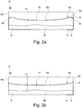
- FIG. 2a is a vertical partial cross section of the cooling element 6 of the strip casting 1 shown in a first embodiment.
- the bottom 6c is provided with a bulge 6d in the first embodiment.
- This curvature 6d is seen in the casting direction G and symmetrical with respect to a center m of the cooling element 6.
- the distance a between the bottom 6c of the cooling element 6 at the center m of the cooling element 6 and the surface of the pre-strip V and the top of the casting belt 4 is minimal and increases in each case starting from the center m to the right and the left side 6e of the cooling element. 6 according to the degree of curvature of the curvature 6d.
- the degree of curvature of the curvature 6d preferably increases.
- the curvature 6d does not terminate in the region of the sides 6e of the cooling element 6 inwardly at a distance therefrom and merges in an edge section 6f parallel to the casting belt 4, which is not curved and thus flat.
- FIG. 2b shows a vertical partial cross-section of the cooling element 6 of the strip casting 1 in a second embodiment.
- the configuration of the underside 6c of the cooling element 6 is comparable to that previously FIG. 2a described. The only difference is that the curvature 6d extends in each case to the sides 6e and thus there are no planar edge sections 6f.
- the degree of curvature of the curvature 6d preferably increases.
- FIGS. 2a and 2b described cross-sectional shapes of the cooling element 6 have in common that a reduced heat dissipation in the lateral edge regions 8 of the solidifying Vorbandes V - seen in the casting direction G - or one improved heat dissipation in the center M of the solidifying Vorbandes V - seen in the casting direction G - takes place.
- a possible bulging of the edge region 8 of the pre-strip V - so-called U-shape - counteracts.
- the thus warmer edge regions 8 of the solidifying Vorbandes V prevent or reduce a rejection of the Vorbandes V, which results from a local increase in temperature of the underside of the solidifying Vorbandes V due to a lifting of the solidifying Vorbandes V from the casting belt 4 in the middle of the solidifying M Vorvorbandes V.
- the aim is to achieve a reduction in the heat dissipation in the edge regions 8 in conjunction with an increase in the heat dissipation in the center M of the solidifying Vorbandes V.
- the minimum distance a between the cooling element 6 and solidifying pre-strip V preferably in the region of the center M of the solidifying pre-strip V, should be 10 to 35 mm.
- the maximum distance a preferably in the edge regions 8 of the solidifying Vorbandes V, should be 45 to 80 mm.
- the underside 6c of the cooling element 6 is seen in cross-section and in the casting direction G in a region around its center m - as described above - curved downwards, whereby the flow velocity of the atmosphere in the enclosure 5 in the region of the center M of solidifying Vorbandes V rises and the direction of flow of the atmosphere of the center M of the solidifying Vorbandes V is directed in the direction of the edge regions 8.
- dust deposits in the region of the center M of the underside 6c of the cooling element 6 are additionally counteracted.
- the curvature 6d leads to an increased settling of the dust in the edge regions 8 of the cooling element 6 and thus advantageously to a reduced heat dissipation in edge regions 8 of the solidifying pre-strip V.
- the cooling element 6 can be subdivided into individual segments, which have at least one cooling circuit over the width of the strip casting plant 1 and have a length of 15 to 150 cm in the casting direction G.
- the solidified top of the pre-strip V has a higher compared to the molten surface thermal emission coefficient, whereby the heat dissipation by radiation increases.
- a coating of the edge region 8 of the cooling element 6 can be made. This coating reduces the thermal conductivity or the heat transfer and / or the thermal absorption coefficient of the cooling element 6 from the surface of the coating into the cooling element 6.
- a coating with a reflective surface can be provided.
- the heat dissipation can be limited for example by applying an insulating layer.
- BN boron nitride, hexagonal
- ZrO 2 ZrO 2
- Al 2 O 3 or AlN are used as the coating for use at high temperatures.
- an insulating layer in the edge region 8 is refractory fiber material, preferably with an Al 2 O 3 content of more than 50 wt .-%, in particular with an Al 2 O 3 content of ⁇ 72 wt .-%, in question.
- the heat transfer is reduced by at least 5% compared to the uncoated areas.
- the distance a of the cooling element 6 to the top of the solidifying Vorbandes V in the region of the center M of the Vorbandes V at a reasonable distance from the melt task preferably at least 0.5 m from the point of application of the melt, to 10 to a maximum of 25 mm, whereby the gas flow velocity of the atmosphere in the housing 5 increases in the region of the lowered cooling element 6 and a deposition of oxides and dusts on the underside 6c of the cooling element 6 is additionally reduced.
- the reduction of the distance a of the cooling element 6 can also be delayed with a lowering of the cooling element 6 only after the start of casting to avoid buildup due to Ang collect bin and to ensure a constant heat removal along the Vorbandes V in the casting direction G at best.
- an additional or alternative solution provides the atmosphere in the Housing 5 in its flow direction to change insofar that the atmosphere is introduced opposite to the casting direction G (countercurrent principle) and thus flows from the end of the housing 5 in the region of the outlet 5b in the direction of the pouring nozzle 3.
- the atmosphere in the Housing 5 in its flow direction to change insofar that the atmosphere is introduced opposite to the casting direction G (countercurrent principle) and thus flows from the end of the housing 5 in the region of the outlet 5b in the direction of the pouring nozzle 3.
- Such horizontal strip casting 1 are particularly suitable for the production of close to near-demarcated Vorband with strip thicknesses in the range of 6 to 25 mm (measured in the band center) of high manganese or high aluminum or high silicon lightweight steels, electrical steel or Hadfield steel.
- a Hadfield steel is generally understood a manganese high carbon steel with carbon from 1 to 1.3 wt .-% and with manganese from 11 to 13 wt .-%.
- the cooling element 6 is formed as a single rectangular parallelepiped extending in the casting direction G. In principle, it is possible, as seen in the casting direction G, to divide the cooling element 6 into a plurality of successive segments. Also, the cooling element 6 may be formed as a ceiling element 5a of the housing 5.
- the cooling element is a circulating cold chain or circulating cooling belt.
- the circulating cold chain or the circulating cooling belt are arranged here with discrete distance to the solidifying Vorband V and develop their cooling effect on recording the radiated from the Vorband V heat.
- the width of the cold chain or the cooling belt is slightly less than the width of the cast Vorbandes V and the cold chain or the cooling belt are moved parallel to the casting belt 4 and / or in or against the casting direction G.
- On an active cooling of the cold chain or the cooling belt with coolant can with sufficient heat capacity - depending on the material and volume / mass of the cold chain or the Cooling belt - be waived.
- Cooling of the cooling element 6 takes place when the cold chain or the cooling belt is returned to the side facing away from the solidifying supernatant V.
- spray or spray water cooling can be used during the return of the cold chain or the cooling belt in order to remove the heat from the cold chain or the cooling belt.
- a cleaning of the cooling element 6 can also be done on return of the cold chain or the cooling belt on the solidifying Vorband V side facing away.
- the used cooling belt can have a thickness between 2 and 15 mm.
Landscapes
- Engineering & Computer Science (AREA)
- Mechanical Engineering (AREA)
- Continuous Casting (AREA)
Abstract
Description
- Die Erfindung betrifft eine Anlage zum horizontalen Bandgießen eines Vorbandes aus Metall.
- Aus der deutschen Patentschrift
DE 44 07 873 C2 ist eine horizontale Bandgießanlage zum Erzeugen eines Vorbandes aus Stahl bekannt. Die Bandgießanlage hat ein Schmelzgefäß, aus der Schmelze über eine Gießdüse auf ein horizontal umlaufendes Gießband aufgegeben wird. Für eine Kühlung des Gießbandes ist unter einem oberen Trum des Gießbandes eine Kühleinrichtung angeordnet. Auf dem gekühlten Gießband erstarrt die aufgegebene Schmelze zu einem Vorband. In dem Bereich zwischen der Gießdüse und dem durcherstarrten Vorband weist die Bandgießanlage eine Einhausung auf, in die ein Gasstrom eingeleitet wird, um für die aufgegebene Schmelze und das erstarrende Vorband eine reduzierende oder oxidierende Atmosphäre oder eine Inertgasatmosphäre zu bilden. Der Gasstrom wird über Düsen, die in einem Deckenelement der Einhausung angeordnet sind, eingeleitet. Um auf die Oberfläche des erstarrenden Vorbandes Einfluss nehmen zu können, wird der Gasstrom in Hinblick auf seine Temperatur und sein Geschwindigkeits- und Druckprofil variiert. - Es ist allgemein bekannt, dass es zeitweise bei der Herstellung von Vorband in einer Banddicke von 6 bis 25 mm durch eine gegenüber dem gekühlten Gießband geringere Wärmeabfuhr an der Oberseite des Vorbandes zu einer Aufwölbung des gegossenen Vorbandes in seitlichen Randbereichen oder einem stellenweisen Abheben des gegossenen Vorbandes von dem Gießband kommen kann. Die Aufwölbungen und das Abheben bedingen ein inhomogenes Profil des gegossenen Vorbandes und größere Lunker, sowie Risse und Poren, was die Weiterverarbeitung deutlich erschwert und das Ausbringen verringert. Die Risse treten in den Randbereichen des gegossenen Vorbandes vermehrt auf und sind in etwa 30 mm bis 100 mm von dem äußeren Rand entfernt. Des Weiteren findet die Aufwölbung der Randbereiche zu einem Zeitpunkt statt, an dem das gegossene Vorband noch nicht durcherstarrt ist und sich auf der Oberfläche flüssige Restschmelze befindet. Das Aufwölben führt dann dazu, dass die Schmelze sich in Richtung Bandmitte verlagert und dadurch bereits erstarrte Dendriten an die Bandoberfläche treten, an der bis zu diesem Zeitpunkt noch keine Deckelbildung stattgefunden hat. Dies führt zu einer offenen Porosität bevorzugt in den Randbereichen, welche bei der Verarbeitung des Bandes zu Oberflächen- und Gefügefehlern führt. Diese Risse mit Oberflächenkontakt führen ebenso zu Materialfehlern während der Weiterverarbeitung, weshalb das Material besäumt werden muss und die Wirtschaftlichkeit sinkt.
- Der vorliegenden Erfindung liegt die Aufgabe zu Grunde, eine Anlage zum horizontalen Bandgießen eines Vorbandes aus Metall zu schaffen, mit der eine verbesserte Qualität des Vorbandes und ein erhöhtes Ausbringen erreicht wird.
- Diese Aufgabe wird durch eine Anlage zum horizontalen Bandgießen eines Vorbandes aus Metall mit den Merkmalen des Anspruches 1 gelöst. Vorteilhafte Ausgestaltungen sind in den Ansprüchen 2 bis 10 angegeben
- Erfindungsgemäß wird bei einer Anlage zum horizontalen Bandgießen eines Vorbandes aus Metall, eine verbesserte Qualität des Vorbandes und ein erhöhtes Ausbringen dadurch erreicht, dass oberhalb des erstarrenden Vorbandes ein Kühlelement zur Kühlung des erstarrenden Vorbandes von oben angeordnet ist. Durch diese verbesserte Kühlung des Vorbandes von oben wird vorteilhafter Weise erreicht, dass das erstarrende Vorband gleichmäßiger gekühlt wird und dies zu einer Herabsetzung von lokalen Spannungen im gegossenen Vorband führt. Diese Spannungen werden sonst durch Risse im Randbereich und/oder Verwerfungen des Stranges (U-Form) abgebaut, d.h. die Bandkanten wölben sich aufgrund der schnelleren Wärmeabfuhr und der damit verbundenen Volumenkontraktion des Gefüges an der Bandunterseite und den Bandkanten auf. Insgesamt wird eine Verbesserung der Qualität, der Oberfläche und der Geometrie eines erzeugten Vorbandes erreicht. Auch wird das Ausbringen erhöht und damit verbunden die Wirtschaftlichkeit. Das Kühlelement ist hierbei mit Abstand zu dem erstarrendem Vorband angeordnet und entfaltet seine Kühlwirkung über Aufnahme der von dem Vorband abgestrahlten Wärme. Insgesamt wird eine Ausbildung einer dichten, nicht offenporigen Oberfläche des Vorbandes erreicht.
- Im Zusammenhang mit der vorliegenden Erfindung wird unter einem Kühlelement ein sich über eine große Fläche erstreckender Körper verstanden, welcher über seine Fläche die durch Wärmestrahlung vom erstarrenden Vorband abgegebene Wärme aufnimmt. Bevorzugt stimmt somit die Fläche des Kühlelements im Wesentlichen mit der Oberfläche des Gießbandes beziehungsweise der Oberfläche des erstarrenden Vorbandes überein. Es ist selbstverständlich, dass hierbei aus konstruktiven Gründen in Gießrichtung gesehen die Länge des Kühlelements am Beginn und am Ende des Gießbandes kürzer ausfallen kann beziehungsweise muss. Auch kann die Breite des Kühlelements bezogen auf das Gießband in den Randbereichen schmaler ausgebildet sein, um die Kühlwirkung in den Randbereichen zu minimieren. Die Fläche des Kühlelements nimmt somit mindestens 50% vorzugsweise 75% der Oberfläche des Gießbandes beziehungsweise der Oberfläche des erstarrenden Vorbandes ein. Das Kühlelement ist bevorzugt metallisch und quaderförmig, wobei anstatt einer flachen Unterseite auch eine gewölbte Unterseite vorgesehen sein kann. Auch ist das Kühlelement bevorzugt ein Hohlkörper. Das erfindungsgemäße Kühlelement umfasst keine Kühlung des erstarrenden Vorbandes durch Spritzwasserkühlung oder Beschickung mit Gasen. Die Kühlung des erfindungsgemäßen Kühlelementes an sich kann aktiv oder passiv - bevorzugt bei einem Hohlkörper über eine Innenkühlung mit Kühlflüssigkeit - erfolgen, um die aufgenommene Wärme aus dem vergossenen Material abzuführen. Auch eine Spritzwasserkühlung einer Oberseite des Kühlelementes, die Anordnung von Kühlrippen, eine Gaskühlung oder eine Kühlung über natürliche Konvektion sind denkbar.
- Neben dieser statischen Anordnung des Kühlelements kann das Kühlelement auch als umlaufendes Kühlband oder umlaufende Kühlkette ausgebildet sein. Die Nutzung der beweglichen Kühlkette oder des beweglichen Kühlbandes als Kühlelement bietet den Vorteil weitgehender Regelmöglichkeiten der Wärmeabfuhr aufgrund der Drehrichtung oder der Geschwindigkeit der Kühlkette oder des Kühlbandes.
- Vorzugsweise ist vorgesehen, dass das Kühlelement zumindest im Bereich einer dem erstarrenden Vorband zugewandten Unterseite aus einem Werkstoff mit einer Wärmeleitfähigkeit von größer 100 W/mK (bei 40 °C), insbesondere von größer 180 W/mK (bei 40 °C), hergestellt ist. Als Werkstoffe eignen sich besonders Aluminium, eine Aluminiumlegierung, Kupfer oder eine Kupferlegierung.
- In einer alternativen oder zusätzlichen Ausführung ist vorgesehen, dass das Kühlelement im Bereich einer dem erstarrenden Vorband zugewandten Unterseite mit einer Oberflächenstruktur versehen ist und die Oberflächenstruktur vorzugsweise ein Pyramiden-, Rauten-, Sicken- oder Punktmuster mit einer Tiefe von 0,5 bis 5 mm im Sinne von Einprägungen oder Erhebungen aufweist. Hierdurch werden Anlagerungen von Staub an das Kühlelement vermieden oder verringert. Auch die Rückreflektion der Wärmestrahlung wird verringert. Zusätzlich wird der für eine reduzierende, inerte oder auf die chemische Zusammensetzung des vergossenen Stahls angepasste Gießatmosphäre in eine Einhausung eingebrachte Gasstrom - im Gegensatz zu einer glatten Oberfläche - gelenkt.
- Eine weitere alternative oder zusätzliche Ausführung sieht vor, dass das Kühlelement im Bereich einer dem erstarrenden Vorband zugewandten Unterseite in Randbereichen mit einer Beschichtung versehen ist, die vorzugsweise BN, ZrO2, Al2O3 oder AIN enthält und besonders vorzugsweise ein feuerfestes Fasermaterial mit einem Al2O3-Gehalt von mehr als 50 Gew.-%, insbesondere mit einem Al2O3-Gehalt von größer gleich 72 Gew.-%, ist. Hierdurch wird eine Homogenisierung der Abkühlbedingungen über die Bandbreite erreicht und somit eine Verformung des abkühlenden Materials (U-Shape) verhindert.
- Noch eine weitere alternative oder zusätzliche Ausführung sieht vor, dass das Kühlelement im Bereich einer dem erstarrenden Vorband zugewandten Unterseite im Querschnitt gesehen in Richtung des erstarrenden Vorband gewölbt ist und die Wölbung in einer Gießrichtung gesehen mittig zum Kühlelement ausgerichtet ist. Die neue Querschnittsform führt auch zu einer Homogenisierung der Abkühlbedingungen über die Brandbreite. Die verringerte Wärmeabfuhr in den Kantenbereichen bewirkt eine Verminderung der Poren- und Lunkerbildung in den Randbereichen.
- In einer alternativen oder zusätzlichen Ausführung ist vorgesehen, dass das Kühlelement in Gießrichtung gesehen in einzelne Segmente unterteilt ist, die über eine Breite des Kühlelements mindestens einen Kühlkreislauf aufweisen und die in Gießrichtung gesehen vorzugsweise eine Länge von 15 bis 150 cm aufweisen. Des Weiteren wird die Messtechnik insofern modifiziert, dass in Gießrichtung gesehen der genaue Ort der Erstarrung der Oberfläche des Vorbandes bezogen auf das Gießband durch Auswertung der Kühlwassertemperaturen einzelner Kühlsegmente bestimmt werden kann.
- Ferner sieht eine weitere alternative oder zusätzliche Ausführung vor, dass das Kühlelement in einem Abstand von 10 bis maximal 25 mm zur Oberseite des erstarrenden Vorbandes im Bereich einer Mitte des erstarrenden Vorbandes und in einer Gießrichtung gesehen in einem angemessenen Abstand von der Schmelzenaufgabe, vorzugsweise mindestens 0,5 m in Gießrichtung von der Schmelzenaufgabe entfernt, angeordnet ist. Bevorzugt ist in diesem Zusammenhang vorgesehen, dass das Kühlelement zur Einstellung eines Abstandes zwischen einer Unterseite des Kühlelements und einer Oberseite des erstarrenden Vorbandes anhebbar und absenkbar ist.
- Hierdurch lässt sich tafelförmiges Vorband mit guter Geometrie und einer verbesserten Oberfläche herstellen. Insbesondere werden Kantenrisse und eine Offenporigkeit der Oberfläche des Vorbandes reduziert beziehungsweise verhindert. Dies bedeutet die Erzeugung eines Vorbandes mit geringeren Fehlern, wodurch ein Ausbringen der horizontalen Bandgießanlage erhöht und damit eine wesentliche Verbesserung von deren Wirtschaftlichkeit erreicht wird.
- Da das erzeugte Vorband beziehungsweise Warmband keine Poren im Randbereich und insgesamt wesentlich geringere Kantenfehler aufweist, wird das sonst zumindest teilweise erforderliche Besäumen des Vorbandes beziehungsweise Warmbandes deutlich reduziert und die Wirtschaftlichkeit der Herstellung erhöht.
- Insgesamt führt die verminderte Wärmeabfuhr zu einer Verminderung von Bandverwerfungen (beispielsweise die bekannte U-Form) des erzeugten Vorbandes. Diese Bandverwerfungen entstehen unter anderem durch zu hohe lokale Wärmeabfuhr im Bereich der Bandkanten.
- Insgesamt kann mit der erfindungsgemäßen horizontalen Bandgießanlage Warmband beziehungsweise Tafelmaterial in der angestrebten Dicke von 6 bis 25 mm (gemessen in der Bandmitte) mit guter Geometrie und verbesserter Oberfläche aus hochmanganhaltigen oder hochaluminiumhaltigen oder hochsiliziumhaltigen Leichtbaustählen, Elektroblechen oder Hadfield-Stahl hergestellt werden.
- Nachfolgend wird die Erfindung an Hand von in Zeichnungen dargestellten Ausführungsbeispielen näher erläutert. Es zeigen:
-
Figur 1 eine schematische Seitenansicht einer horizontalen Bandgießanlage, -
Figur 2a einen vertikalen Teil-Querschnitt eines Kühlelementes der Bandgießanlage ausFigur 1 in einer ersten Ausführungsform und -
Figur 2b einen vertikalen Teil-Querschnitt des Kühlelementes in einer zweiten Ausführungsform. - Die in
Figur 1 gezeigte schematische Seitenansicht einer horizontalen Bandgießanlage 1 besteht im Wesentlichen aus einem Schmelzgefäß 2, einer Gießdüse 3, einem Gießband 4 und einer Einhausung 5 mit einem Kühlelement 6, das auch als Topcooler bezeichnet werden kann. Über das Schmelzgefäß 2 wird flüssige Schmelze S, insbesondere Metallschmelze, über eine sich hieran anschließende Gießdüse 3 auf das Gießband 4 in Form eines Stranges beziehungsweise erstarrenden Vorbandes V aufgegeben. Hierbei läuft das endlose Gießband 4 in einer Gießrichtung G um eine vordere Umlenkrolle 4a und eine hiervon in Gießrichtung G beabstandete hintere Umlenkrolle 4b um und fördert das erstarrende Vorband V somit in Gießrichtung G. Entsprechender Weise lässt sich das Gießband 4 in ein oberes Trum 4c, auf dem das Vorband V erstarrt und das sich oben zwischen den vorderen und hinteren Umlenkrollen 4a, 4b erstreckt, und ein unteres Trum 4d aufteilen, das sich unten zwischen den vorderen und hinteren Umlenkrollen 4a, 4b erstreckt. Das Gießband 4 verläuft im Bereich des oberen Trums 4c im Wesentlichen horizontal und ist im Bereich des oberen Trums 4c mittels einer Kühlvorrichtung 7 von unten gekühlt, die nahezu das gesamte Obertrum 4c unter Ausnahme kurzer Bereiche am Übergang zu den Umlenkrollen 4a, 4b von unten mit Kühlmittel, vorzugsweise Wasser, beaufschlagt. Aus Gründen der Übersichtlichkeit sind üblicher Weise vorhandene und sich in Gießrichtung G erstreckende Seitenbegrenzungselemente für das auf dem Obertrum 4c erstarrende Vorband V nicht dargestellt. Die Einhausung 5 der horizontalen Bandgießanlage 1 umschließt das erstarrende Vorband V in einem Bereich zwischen der Gießdüse 3 und einem Austritt 5b für das durcherstarrte Vorband V aus der Einhausung 5. Die Einhausung 5 ist in üblicher Weise vorgesehen, um die Schmelze S in einer reduzierenden Atmosphäre, einer Inertgasatmosphäre oder einer auf die chemische Zusammensetzung des vergossenen Stahls angepassten Gießatmosphäre, zu vergießen und zu dem Vorband V erstarren zu lassen. Hierfür sind an die Einhausung 5 im Bereich eines oberen und im Wesentlichen sich horizontal erstreckenden Deckenelements 5a eine Gaszuleitung 5c und eine Gasableitung 5d angeschlossen. Die Gaszuleitung 5c befindet sich im Bereich des Austritts 5b und die Gasableitung 5d im Bereich der Gießdüse, so dass das Gas entgegen der Gießrichtung G im Gegenstrom zu dem erstarrenden Vorband V strömt. - Neben der Kühlung des erstarrenden Vorbandes V mit der Kühlvorrichtung 7 von unten, die mit dem erstarrenden Vorband V über das Gießband 4 direkt in Kontakt steht, ist eine zusätzliche Kühlung des erstarrenden Vorbandes V von oben mit einem Kühlelement 6 vorgesehen. Das Kühlelement 6 ist innerhalb der Einhausung 5 und oberhalb des erstarrenden Vorbandes V angeordnet. In Gießrichtung G gesehen erstreckt sich das Kühlelement 6 von einem Bereich, der sich an die Gießdüse 3 anschließt, bis zu einem Bereich in der Nähe des Austritts 5b des Vorbandes V aus der Einhausung 5 und mindestens über die gesamte Breite des erstarrenden Vorbandes V beziehungsweise des Gießbandes 4. Das Kühlelement 6 an sich ist ein flacher quaderförmiger Hohlkörper, der von einem Kühlmittel, vorzugsweise Wasser, über eine Zuleitung 6a und Ableitung 6b im Gegenstrom zur Gießrichtung G oder in Gießrichtung G durchströmt wird. Da das Kühlelement 6 in einem vorgewählten Abstand a oberhalb des erstarrenden Vorbandes V angeordnet ist, führt das Kühlelement 6 die von dem erstarrenden Vorband V abgegebene Wärmestrahlung ab und trägt somit zur Kühlung des erstarrenden Vorbandes V von oben bei. Der Abstand a erstreckt sich hierbei lotrecht zwischen der Oberseite des erstarrenden Vorband V und der Unterseite 6c des Kühlelements 6.
- Für die Herstellung des Kühlelements 6 sind Werkstoffe wie Aluminium, Aluminiumlegierungen, Kupfer oder Kupferlegierung geeignet. Diese Werkstoffe haben eine Wärmeleitfähigkeit von größer 100 W/mK (bei 40 °C), vorzugsweise von größer 180 W/mK (bei 40 °C).
- Insbesondere ist zusätzlich oder alternativ vorgesehen, das Kühlelement 6 an seiner dem erstarrenden Vorband V zugewandten Unterseite 6c mit einer Oberflächenstruktur anstatt mit einer planen Oberfläche zu versehen. Während des Gießprozesses entstehen Stäube, die im Wesentlichen aus Fe-, Mn-, Zn- und Pb-Oxiden sowie geringen Mengen an C und Cl bestehen und sich in Form einer Staubschicht an der Unterseite 6c des Kühlelements 6 absetzen. Da die Staubschicht eine geringere Wärmeleitfähigkeit als das Kühlelement 6 aufweist, wird hierdurch die Kühlleistung des Kühlelements 6 herabgesetzt. Die Oberflächenstruktur der Unterseite 6c wirkt dem Absetzen der Staubschicht entgegen, so dass die Wärmeabfuhr durch die Staubschicht nicht behindert wird. Als Oberflächenstruktur kommen beispielsweise ein Pyramiden-, Rauten-, Sicken- oder Punktmuster mit einer Tiefe von 0,5 bis 5 mm im Sinne von Einprägungen oder Erhebungen in Frage. Die Tiefe von 0,5 bis 5 mm ist hierbei lotrecht auf den nicht mit einer Oberflächenstruktur versehenen Teil der Unterseite 6c des Kühlelements 6 bezogen. Durch die Oberflächenstruktur entstehen kleine Verwirbelungen der Atmosphäre in der Einhausung 5 im Bereich der Kanten der jeweiligen Oberflächenstruktur. Hierdurch wird das gleichmäßige Absetzen der Staubschicht verhindert. Zusätzlich löst sich der Staub, welcher sich in tieferen Bereichen der Oberflächenstruktur sammelt, nach Erreichen einer kritischen Dicke selbsttätig ab und wird mit dem erstarrendem Vorband V ausgefördert beziehungsweise verbrennt. Auch vergrößert die Oberflächenstruktur die Oberfläche der Unterseite 6c insgesamt und somit die Kühlfläche. Ferner bewirkt die Oberflächenstruktur eine Veränderung der Reflektionswinkel in Bezug auf die Wärmestrahlung von dem erstarrenden Vorband. Hierdurch wird die zurückgestrahlte Wärme auf das erstarrende Vorband V um mindestens 5 % verringert, wodurch eine höhere Kühlleistung des Kühlelements 6 erzielt wird. Alternativ ist es möglich, den Gasstrom durch eine Topographie mit Sicken (Längsnuten) zu lenken.
- In der
Figur 1 ist das Kühlelement 6 als ein einzelnes sich in Gießrichtung G erstreckendes quaderförmiges Hohlelement ausgebildet. - In der
Figur 2a ist ein vertikaler Teil-Querschnitt des Kühlelementes 6 der Bandgießanlage 1 in einer ersten Ausführungsform dargestellt. Anstatt einer quaderförmigen Querschnittsform mit einer planen Unterseite 6c ist die Unterseite 6c in der ersten Ausführungsform mit einer Wölbung 6d versehen. Diese Wölbung 6d ist in Gießrichtung G gesehen und auf eine Mitte m des Kühlelementes 6 bezogen symmetrisch. Der Abstand a zwischen der Unterseite 6c des Kühlelementes 6 an der Mitte m des Kühlelementes 6 und der Oberfläche des Vorbandes V beziehungsweise der Oberseite des Gießbandes 4 ist minimal und steigt jeweils ausgehend von der Mitte m zu der rechten und der linken Seite 6e des Kühlelementes 6 entsprechend dem Krümmungsgrad der Wölbung 6d an. Ausgehend von der Mitte m zu den Seiten 6e hin nimmt der Krümmungsgrad der Wölbung 6d vorzugsweise zu. Zusätzlich endet die Wölbung 6d nicht im Bereich der Seiten 6e des Kühlelementes 6 nach innen mit Abstand hierzu und geht in einer zu dem Gießband 4 parallelen Randabschnitt 6f über, der nicht gewölbt und somit plan ist. - Die
Figur 2b zeigt einen vertikalen Teil-Querschnitt des Kühlelementes 6 der Bandgießanlage 1 in einer zweiten Ausführungsform. Die Ausgestaltung der Unterseite 6c des Kühlelementes 6 ist vergleichbar mit der zuvor zuFigur 2a beschriebenen. Der einzige Unterschied besteht darin, dass die Wölbung 6d jeweils bis an die Seiten 6e reicht und somit keine planen Randabschnitte 6f vorhanden sind. Auch hier nimmt ausgehend von der Mitte m zu den Seiten 6e hin der Krümmungsgrad der Wölbung 6d vorzugsweise zu. - Die in den
Figuren 2a und 2b beschriebenen Querschnittsformen des Kühlelementes 6 haben gemeinsam, dass eine verringerte Wärmeabfuhr in den seitlichen Randbereichen 8 des erstarrenden Vorbandes V - in Gießrichtung G gesehen - beziehungsweise eine verbesserte Wärmeabfuhr in der Mitte M des erstarrenden Vorbandes V - in Gießrichtung G gesehen - erfolgt. Hierdurch wird einem etwaigen Aufwölben des Randbereiches 8 des Vorbandes V - sogenannter U-Shape - entgegenwirkt. Die dadurch wärmeren Randbereiche 8 des erstarrenden Vorbandes V verhindern beziehungsweise verringern eine Verwerfung des Vorbandes V, welche aus einer lokalen Temperaturerhöhung der Unterseite des erstarrenden Vorbandes V aufgrund eines Abhebens des erstarrenden Vorbandes V vom Gießband 4 im Bereich der Mitte M des erstarrenden Vorbandes V resultiert. Ziel ist es, eine Verringerung der Wärmeabfuhr in den Randbereichen 8 in Verbindung mit einer Erhöhung der Wärmeabfuhr in der Mitte M des erstarrenden Vorbandes V zu erreichen. Der minimale Abstand a zwischen Kühlelement 6 und erstarrendem Vorband V, vorzugsweise im Bereich der Mitte M des erstarrenden Vorbandes V, soll 10 bis 35 mm betragen. Der maximale Abstand a, vorzugsweise in den Randbereichen 8 des erstarrenden Vorbandes V, soll 45 bis 80 mm betragen. Um dies zu erreichen, wird die Unterseite 6c des Kühlelements 6 im Querschnitt und in Gießrichtung G gesehen in einem Bereich um seine Mitte m - wie zuvor beschrieben - nach unten gewölbt, wodurch die Strömungsgeschwindigkeit der Atmosphäre in der Einhausung 5 im Bereich der Mitte M des erstarrenden Vorbandes V steigt und die Strömungsrichtung der Atmosphäre von der Mitte M des erstarrenden Vorbandes V in Richtung der Randbereiche 8 gelenkt wird. Damit wird zusätzlich auch Staubablagerungen im Bereich der Mitte M der Unterseite 6c des Kühlelements 6 entgegengewirkt. Weiterhin positiv führt die Wölbung 6d zu einem verstärkten Absetzen des Staubes in den Randbereichen 8 des Kühlelements 6 und somit vorteilhaft zu einer verringerten Wärmeabfuhr in Randbereichen 8 des erstarrenden Vorbandes V. Außerdem wird ein Risiko, dass ein sich im Randbereich 8 aufwölbendes Vorband V das Kühlelement 6 berührt, verringert. - Auch kann zusätzlich oder alternativ das Kühlelement 6 in einzelne Segmente unterteilt werden, welche über die Breite der Bandgießanlage 1 mindestens einen Kühlkreislauf aufweisen und in Gießrichtung G eine Länge von 15 bis 150 cm aufweisen. Die erstarrte Oberseite des Vorbandes V weist einen im Vergleich zur schmelzflüssigen Oberfläche höheren thermischen Emissionskoeffizienten auf, wodurch die Wärmeabfuhr durch Strahlung ansteigt. Durch die Messung der Kühlwassertemperaturen der einzelnen Segmente und die daraus berechnete aufgenommene Wärmemenge kann verlässlich festgestellt werden, in welchem Bereich beziehungsweise an welchem Ort der Bandgießanlage 1 die Erstarrung der Oberfläche des erstarrenden Vorbandes V erfolgt. Hierdurch kann die Gießgeschwindigkeit für die jeweiligen Legierungen und Gießdicken optimal angepasst werden, so auch zur exakten Positionierung der Resterstarrung.
- Des Weiteren kann zusätzlich oder alternativ eine Beschichtung des Randbereiches 8 des Kühlelements 6 vorgenommen werden. Diese Beschichtung vermindert die Wärmeleitfähigkeit beziehungsweise den Wärmeübergang und/oder den thermischen Absorptionskoeffizienten des Kühlelements 6 von der Oberfläche der Beschichtung in das Kühlelement 6. Beispielsweise kann eine Beschichtung mit spiegelnder Oberfläche vorgesehen werden. Die Wärmeabfuhr kann beispielsweise durch Aufbringen einer Isolierschicht begrenzt werden. Als Beschichtung für die Anwendung bei hohen Temperaturen kommen dabei insbesondere BN (Bornitrid, hexagonal), ZrO2, Al2O3 oder AIN zum Einsatz. Als Isolierschicht in dem Randbereich 8 kommt feuerfestes Fasermaterial, vorzugsweise mit einem Al2O3-Gehalt von mehr als 50 Gew.-%, insbesondere mit einem Al2O3-Gehalt von ≥ 72 Gew.-%, in Frage. Der Wärmeübergang wird dabei im Vergleich zu den nicht beschichteten Bereichen um mindestens 5 % gesenkt.
- Wiederum zusätzlich oder alternativ kann der Abstand a des Kühlelementes 6 zur Oberseite des erstarrenden Vorbandes V im Bereich der Mitte M des Vorbandes V in einem angemessenen Abstand von der Schmelzenaufgabe, vorzugsweise mindestens 0,5 m vom Aufgabepunkt der Schmelze entfernt, auf 10 bis maximal 25 mm verringert werden, wodurch die Gasströmungsgeschwindigkeit der Atmosphäre in der Einhausung 5 im Bereich des abgesenkten Kühlelements 6 erhöht und eine Ablagerung von Oxiden und Stäuben an der Unterseite 6c des Kühlelements 6 zusätzlich vermindert wird. Die Verringerung des Abstands a des Kühlelements 6 kann dabei auch zeitverzögert durch ein Absenken des Kühlelements 6 erst nach Gießbeginn erfolgen, um Anhaftungen infolge von Angießeffekten zu vermeiden und eine bestenfalls konstante Wärmeabfuhr entlang des Vorbandes V in Gießrichtung G zu gewährleisten.
- Auch eine zusätzliche oder alternative Lösung sieht vor, die Atmosphäre in der Einhausung 5 in ihrer Strömungsrichtung insofern zu ändern, dass die Atmosphäre entgegengesetzt zur Gießrichtung G eingebracht wird (Gegenstromprinzip) und somit vom Ende der Einhausung 5 im Bereich des Austritts 5b in Richtung der Gießdüse 3 strömt. Damit wird neben der Vermeidung von für die Wärmeabfuhr ungünstigen Strömungsgrenzschichten in Gießrichtung G parallel die Ablagerung einer die Wärmeabfuhr behindernden Staubschicht an der Unterseite 6c des Kühlelements 6, insbesondere im Bereich der Erstarrung der Oberfläche des erstarrenden Vorbandes V, vermindert.
- Derartige horizontale Bandgießanlagen 1 eignen sich besonders zur Erzeugung von endabmessungsnahem Vorband mit Banddicken im Bereich von 6 bis 25 mm (gemessen in der Bandmitte) aus hochmanganhaltigen oder hochaluminiumhaltigen oder hochsiliziumhaltigen Leichtbaustählen, Elektroblechen oder Hadfield-Stahl. Unter einem Hadfield-Stahl wird im Allgemeinen ein Mangan-Hartstahl verstanden mit Kohlenstoff von 1 bis 1,3 Gew.-% und mit Mangan von 11 bis 13 Gew.-%.
- In dem vorliegenden Ausführungsbeispiel ist das Kühlelement 6 als ein einzelnes sich in Gießrichtung G erstreckendes quaderförmiges Hohlelement ausgebildet. Grundsätzlich ist es möglich, in Gießrichtung G gesehen das Kühlelement 6 in mehrere aufeinander folgende Segmente aufzuteilen. Auch kann das Kühlelement 6 als Deckenelement 5a der Einhausung 5 ausgebildet sein.
- Des Weiteren ist es möglich, das Kühlelement als umlaufende Kühlkette oder umlaufendes Kühlband auszubilden. Genauso wie das statische Kühlelement 6 sind die umlaufende Kühlkette oder das umlaufende Kühlband hierbei mit diskretem Abstand zu dem erstarrenden Vorband V angeordnet und entfalten ihre Kühlwirkung über Aufnahme der von dem Vorband V abgestrahlten Wärme. Vorzugsweise ist die Breite der Kühlkette oder des Kühlbandes etwas geringer als die Breite des gegossenen Vorbandes V und die Kühlkette oder das Kühlband werden parallel zu dem Gießband 4 und/oder in beziehungsweise entgegen der Gießrichtung G bewegt. Auf eine aktive Kühlung der Kühlkette oder des Kühlbandes mit Kühlflüssigkeit kann bei ausreichender Wärmekapazität - abhängig vom Werkstoff sowie Volumen/Masse der Kühlkette oder des Kühlbandes - verzichtet werden. Eine Abkühlung des Kühlelements 6 erfolgt bei Rückführung der Kühlkette oder des Kühlbandes auf der dem erstarrenden Vorband V abgewandten Seite. Alternativ zur Kühlung durch Wärmestrahlung kann eine Spritz- oder Sprühwasserkühlung während der Rückführung der Kühlkette oder des Kühlbandes eingesetzt werden, um die Wärme aus der Kühlkette oder dem Kühlband abzuführen. Eine Reinigung des Kühlelements 6 kann ebenso bei Rückführung der Kühlkette oder des Kühlbandes auf der dem erstarrenden Vorband V abgewandten Seite erfolgen. Das eingesetzte Kühlband kann eine Dicke zwischen 2 und 15 mm aufweisen.
-
- 1 horizontale Bandgießanlage
- 2 Schmelzgefäß
- 3 Gießdüse
- 4 Gießband
- 4a vordere Umlenkrolle
- 4b hintere Umlenkrolle
- 4c oberes Trum
- 4d unteres Trum
- 5 Einhausung
- 5a Deckenelement
- 5b Austritt
- 5c Gaszuleitung
- 5d Gasableitung
- 6 Kühlelement
- 6a Zuleitung
- 6b Ableitung
- 6c Unterseite
- 6d Wölbung
- 6e Seite
- 6f Randabschnitt
- 7 Kühlvorrichtung
- 8 Randbereich
- a Abstand
- m Mitte
- G Gießrichtung
- M Mitte
- S Schmelze
- V Vorband
Claims (10)
- Anlage zum horizontalen Bandgießen eines Vorbandes (V) aus Metall, dadurch gekennzeichnet, dass oberhalb des erstarrenden Vorbandes (V) ein Kühlelement (6) zur Kühlung des erstarrenden Vorbandes (V) von oben angeordnet ist.
- Anlage nach Anspruch 1, dadurch gekennzeichnet, dass das Kühlelement (6) statisch angeordnet ist oder als umlaufendes Kühlband oder Kühlkette ausgeführt ist.
- Anlage nach Anspruch 1 oder 2, dadurch gekennzeichnet, dass das Kühlelement (6) zumindest im Bereich einer dem erstarrenden Vorband (V) zugewandten Unterseite (6c) aus einem Werkstoff mit einer Wärmeleitfähigkeit von größer 100 W/mK (bei 40 °C), insbesondere von größer 180 W/mK (bei 40 °C), hergestellt ist.
- Anlage nach einem oder mehreren der Ansprüche 1 bis 3, dadurch gekennzeichnet, dass der Werkstoff Aluminium, eine Aluminiumlegierung, Kupfer oder eine Kupferlegierung ist.
- Anlage nach einem oder mehreren der Ansprüche 1 bis 4, dadurch gekennzeichnet, dass das Kühlelement (6) im Bereich einer dem erstarrenden Vorband (V) zugewandten Unterseite (6c) mit einer Oberflächenstruktur versehen ist und die Oberflächenstruktur vorzugsweise ein Pyramiden-, Rauten-, Sicken- oder Punktmuster mit einer Tiefe von 0,5 bis 5 mm im Sinne von Einprägungen oder Erhebungen aufweist.
- Anlage nach einem oder mehreren der Ansprüche 1 bis 5, dadurch gekennzeichnet, dass das Kühlelement (6) im Bereich einer dem erstarrenden Vorband (V) zugewandten Unterseite (6c) im Randbereich mit einer Beschichtung versehen ist, die vorzugsweise BN, ZrO2, Al2O3 oder AIN enthält und besonders vorzugsweise ein feuerfestes Fasermaterial mit einem Al2O3-Gehalt von mehr als 50 Gew.-%, insbesondere mit einem Al2O3-Gehalt von größer gleich 72 Gew.-%, ist.
- Anlage nach einem der Ansprüche 1 bis 6, dadurch gekennzeichnet, dass das Kühlelement (6) im Bereich einer dem erstarrenden Vorband (V) zugewandten Unterseite (6c) im Querschnitt gesehen in Richtung des erstarrenden Vorband (V) gewölbt ist und die Wölbung in einer Gießrichtung (G) gesehen mittig zum Kühlelement (6) ausgerichtet ist.
- Anlage nach einem der Ansprüche 1 bis 7, dadurch gekennzeichnet, dass das Kühlelement (6) in einer Gießrichtung (G) gesehen in einzelne Segmente unterteilt ist, die über eine Breite des Kühlelements (6) mindestens einen Kühlkreislauf aufweisen und die in Gießrichtung (G) gesehen vorzugsweise eine Länge von 15 bis 150 cm aufweisen.
- Anlage nach einem der Ansprüche 1 bis 8, dadurch gekennzeichnet, dass das Kühlelement (6) in einem Abstand (a) von 10 bis maximal 25 mm zur Oberseite des erstarrenden Vorbandes (V) im Bereich einer Mitte (M) des erstarrenden Vorbandes (V) und in einer Gießrichtung (G) gesehen in einem angemessenen Abstand von der Schmelzenaufgabe, vorzugsweise mindestens 0,5 m von der Schmelzenaufgabe, angeordnet ist.
- Anlage nach einem der Ansprüche 1 bis 9, dadurch gekennzeichnet, dass das Kühlelement (6) zur Einstellung eines Abstandes (a) zwischen einer Unterseite (6c) des Kühlelements (6) und einer Oberseite des erstarrenden Vorbandes (V) anhebbar und absenkbar ist.
Applications Claiming Priority (1)
| Application Number | Priority Date | Filing Date | Title |
|---|---|---|---|
| DE102017104279.2A DE102017104279A1 (de) | 2017-03-01 | 2017-03-01 | Horizontale Bandgießanlage mit optimierter Kühlung |
Publications (2)
| Publication Number | Publication Date |
|---|---|
| EP3369496A1 true EP3369496A1 (de) | 2018-09-05 |
| EP3369496B1 EP3369496B1 (de) | 2021-05-12 |
Family
ID=61283028
Family Applications (1)
| Application Number | Title | Priority Date | Filing Date |
|---|---|---|---|
| EP18158502.7A Active EP3369496B1 (de) | 2017-03-01 | 2018-02-26 | Horizontale bandgiessanlage mit optimierter kühlung |
Country Status (2)
| Country | Link |
|---|---|
| EP (1) | EP3369496B1 (de) |
| DE (1) | DE102017104279A1 (de) |
Citations (4)
| Publication number | Priority date | Publication date | Assignee | Title |
|---|---|---|---|---|
| US5074353A (en) * | 1990-02-19 | 1991-12-24 | Kabushiki Kaisha O. C. C. | Method for horizontal continuous casting of metal strip and apparatus therefor |
| DE4407873C2 (de) * | 1994-03-04 | 1997-04-10 | Mannesmann Ag | Verfahren und Vorrichtung zum Kühlen schmelzflüssigen Stahls |
| DE19917250A1 (de) * | 1999-04-16 | 2000-10-19 | Mannesmann Ag | Verfahren und Vorrichtung zum Vergleichmäßigen einer schmelzflüssigen Metallschicht |
| DE102008031476A1 (de) * | 2007-08-16 | 2009-02-19 | Sms Demag Ag | Gießvorrichtung |
Family Cites Families (3)
| Publication number | Priority date | Publication date | Assignee | Title |
|---|---|---|---|---|
| GB1551755A (en) | 1977-06-21 | 1979-08-30 | British Steel Corp | Continuous casting of metal strip |
| US5299628A (en) | 1991-07-03 | 1994-04-05 | Olin Corporation | Method and apparatus for the casting of molten metal |
| DE102012010038B4 (de) | 2012-05-16 | 2020-11-19 | Salzgitter Flachstahl Gmbh | Verfahren zum Herstellen eines Metallbandes auf einem bewegten Transportband |
-
2017
- 2017-03-01 DE DE102017104279.2A patent/DE102017104279A1/de not_active Withdrawn
-
2018
- 2018-02-26 EP EP18158502.7A patent/EP3369496B1/de active Active
Patent Citations (4)
| Publication number | Priority date | Publication date | Assignee | Title |
|---|---|---|---|---|
| US5074353A (en) * | 1990-02-19 | 1991-12-24 | Kabushiki Kaisha O. C. C. | Method for horizontal continuous casting of metal strip and apparatus therefor |
| DE4407873C2 (de) * | 1994-03-04 | 1997-04-10 | Mannesmann Ag | Verfahren und Vorrichtung zum Kühlen schmelzflüssigen Stahls |
| DE19917250A1 (de) * | 1999-04-16 | 2000-10-19 | Mannesmann Ag | Verfahren und Vorrichtung zum Vergleichmäßigen einer schmelzflüssigen Metallschicht |
| DE102008031476A1 (de) * | 2007-08-16 | 2009-02-19 | Sms Demag Ag | Gießvorrichtung |
Non-Patent Citations (1)
| Title |
|---|
| S. GE, M. ISAC, R.I.L. GUTHRIE: "Progress in Strip Casting Technologies for Steel; Technical Developments", ISIJ INTERNATIONAL, vol. 53, no. 5, 2013, XP002780589 * |
Also Published As
| Publication number | Publication date |
|---|---|
| DE102017104279A1 (de) | 2018-09-06 |
| EP3369496B1 (de) | 2021-05-12 |
Similar Documents
| Publication | Publication Date | Title |
|---|---|---|
| DE60208274T2 (de) | Segmentierte Wärmedämmschicht und Verfahren zu ihrer Herstellung | |
| DE3855653T2 (de) | Vorrichtung und Verfahren zum direkten Giessen von Metallband | |
| DE4306943C2 (de) | Anfahrkopf für eine Vertikal-Stranggießanlage | |
| EP1937429A1 (de) | Verfahren und vorrichtung zum stranggiessen | |
| DE69518360T2 (de) | Stranggiesskokille mit verbessertem Wärmeaustausch sowie Verfahren zur Erhöhung des Wärmeaustauschs einer Stranggiesskokille | |
| AT412194B (de) | Verbesserte kokille für eine stranggiessanlage sowie verfahren | |
| EP3375544B1 (de) | Horizontale bandgiessanlage mit optimiertem giessband | |
| EP3369496B1 (de) | Horizontale bandgiessanlage mit optimierter kühlung | |
| DE69029467T2 (de) | Stranggussform und Stranggussverfahren | |
| DE60316568T3 (de) | Bandtemperaturregelvorrichtung in einer kontinuierlichen bandgiessanlage | |
| DE3029223C2 (de) | Einlauf für die Metallschmelze in Stranggießvorrichtungen | |
| DE69929382T2 (de) | Kühltrommel für eine Doppelrollen-Stranggussanlage | |
| EP1736257A2 (de) | Flüssigkeitsgekühlte Kokille zum Stranggiessen von Metallen | |
| WO2011018076A1 (de) | Giessform | |
| DE68906312T2 (de) | Begrenzungswand fuer bandstranggiessanlagen. | |
| EP1019208B1 (de) | Kokillenrohr für eine stranggiesskokille zum stranggiessen von stählen, insbesondere peritektischen stählen | |
| EP0208890B1 (de) | Verfahren zum Herstellen eines Metallstranges, insbesondere in Form eines Bandes oder Profils durch Giessen und Vorrichtung zur Durchführung dieses Verfahrens | |
| DE4344954C1 (de) | Transportband einer Bandstranggießeinrichtung zum Gießen von Bändern aus Metall | |
| DE2621588C3 (de) | Verfahren zum Erschmelzen von mehrschichtigen Metallblöcken und Elektronenstrahlanlage zur Durchführung dieses Verfahrens | |
| DE69909052T2 (de) | Vertikal-stranggiesskokille mit aufsatz | |
| DE102013114326A1 (de) | Gießkokille zum Vergießen von Stahlschmelze | |
| DE2627406B2 (de) | Metallgießform mit sich nach unten erweiterndem Querschnitt | |
| EP0869853B1 (de) | Verfahren zum stranggiessen von dünnbrammen aus metall | |
| AT402266B (de) | Stranggiessanlage | |
| DE102017103046A1 (de) | Horizontale Bandgießanlage mit optimierter Gießatmosphäre |
Legal Events
| Date | Code | Title | Description |
|---|---|---|---|
| STAA | Information on the status of an ep patent application or granted ep patent |
Free format text: STATUS: EXAMINATION IS IN PROGRESS |
|
| PUAI | Public reference made under article 153(3) epc to a published international application that has entered the european phase |
Free format text: ORIGINAL CODE: 0009012 |
|
| 17P | Request for examination filed |
Effective date: 20180226 |
|
| AK | Designated contracting states |
Kind code of ref document: A1 Designated state(s): AL AT BE BG CH CY CZ DE DK EE ES FI FR GB GR HR HU IE IS IT LI LT LU LV MC MK MT NL NO PL PT RO RS SE SI SK SM TR |
|
| AX | Request for extension of the european patent |
Extension state: BA ME |
|
| RBV | Designated contracting states (corrected) |
Designated state(s): AL AT BE BG CH CY CZ DE DK EE ES FI FR GB GR HR HU IE IS IT LI LT LU LV MC MK MT NL NO PL PT RO RS SE SI SK SM TR |
|
| GRAP | Despatch of communication of intention to grant a patent |
Free format text: ORIGINAL CODE: EPIDOSNIGR1 |
|
| STAA | Information on the status of an ep patent application or granted ep patent |
Free format text: STATUS: GRANT OF PATENT IS INTENDED |
|
| INTG | Intention to grant announced |
Effective date: 20201202 |
|
| GRAS | Grant fee paid |
Free format text: ORIGINAL CODE: EPIDOSNIGR3 |
|
| GRAA | (expected) grant |
Free format text: ORIGINAL CODE: 0009210 |
|
| STAA | Information on the status of an ep patent application or granted ep patent |
Free format text: STATUS: THE PATENT HAS BEEN GRANTED |
|
| AK | Designated contracting states |
Kind code of ref document: B1 Designated state(s): AL AT BE BG CH CY CZ DE DK EE ES FI FR GB GR HR HU IE IS IT LI LT LU LV MC MK MT NL NO PL PT RO RS SE SI SK SM TR |
|
| REG | Reference to a national code |
Ref country code: GB Ref legal event code: FG4D Free format text: NOT ENGLISH |
|
| REG | Reference to a national code |
Ref country code: CH Ref legal event code: EP |
|
| REG | Reference to a national code |
Ref country code: DE Ref legal event code: R096 Ref document number: 502018005196 Country of ref document: DE |
|
| REG | Reference to a national code |
Ref country code: IE Ref legal event code: FG4D Free format text: LANGUAGE OF EP DOCUMENT: GERMAN |
|
| REG | Reference to a national code |
Ref country code: AT Ref legal event code: REF Ref document number: 1391845 Country of ref document: AT Kind code of ref document: T Effective date: 20210615 |
|
| REG | Reference to a national code |
Ref country code: LT Ref legal event code: MG9D |
|
| REG | Reference to a national code |
Ref country code: NL Ref legal event code: MP Effective date: 20210512 |
|
| PG25 | Lapsed in a contracting state [announced via postgrant information from national office to epo] |
Ref country code: FI Free format text: LAPSE BECAUSE OF FAILURE TO SUBMIT A TRANSLATION OF THE DESCRIPTION OR TO PAY THE FEE WITHIN THE PRESCRIBED TIME-LIMIT Effective date: 20210512 Ref country code: LT Free format text: LAPSE BECAUSE OF FAILURE TO SUBMIT A TRANSLATION OF THE DESCRIPTION OR TO PAY THE FEE WITHIN THE PRESCRIBED TIME-LIMIT Effective date: 20210512 Ref country code: HR Free format text: LAPSE BECAUSE OF FAILURE TO SUBMIT A TRANSLATION OF THE DESCRIPTION OR TO PAY THE FEE WITHIN THE PRESCRIBED TIME-LIMIT Effective date: 20210512 Ref country code: BG Free format text: LAPSE BECAUSE OF FAILURE TO SUBMIT A TRANSLATION OF THE DESCRIPTION OR TO PAY THE FEE WITHIN THE PRESCRIBED TIME-LIMIT Effective date: 20210812 |
|
| PG25 | Lapsed in a contracting state [announced via postgrant information from national office to epo] |
Ref country code: GR Free format text: LAPSE BECAUSE OF FAILURE TO SUBMIT A TRANSLATION OF THE DESCRIPTION OR TO PAY THE FEE WITHIN THE PRESCRIBED TIME-LIMIT Effective date: 20210813 Ref country code: IS Free format text: LAPSE BECAUSE OF FAILURE TO SUBMIT A TRANSLATION OF THE DESCRIPTION OR TO PAY THE FEE WITHIN THE PRESCRIBED TIME-LIMIT Effective date: 20210912 Ref country code: NO Free format text: LAPSE BECAUSE OF FAILURE TO SUBMIT A TRANSLATION OF THE DESCRIPTION OR TO PAY THE FEE WITHIN THE PRESCRIBED TIME-LIMIT Effective date: 20210812 Ref country code: PL Free format text: LAPSE BECAUSE OF FAILURE TO SUBMIT A TRANSLATION OF THE DESCRIPTION OR TO PAY THE FEE WITHIN THE PRESCRIBED TIME-LIMIT Effective date: 20210512 Ref country code: LV Free format text: LAPSE BECAUSE OF FAILURE TO SUBMIT A TRANSLATION OF THE DESCRIPTION OR TO PAY THE FEE WITHIN THE PRESCRIBED TIME-LIMIT Effective date: 20210512 Ref country code: PT Free format text: LAPSE BECAUSE OF FAILURE TO SUBMIT A TRANSLATION OF THE DESCRIPTION OR TO PAY THE FEE WITHIN THE PRESCRIBED TIME-LIMIT Effective date: 20210913 Ref country code: RS Free format text: LAPSE BECAUSE OF FAILURE TO SUBMIT A TRANSLATION OF THE DESCRIPTION OR TO PAY THE FEE WITHIN THE PRESCRIBED TIME-LIMIT Effective date: 20210512 Ref country code: SE Free format text: LAPSE BECAUSE OF FAILURE TO SUBMIT A TRANSLATION OF THE DESCRIPTION OR TO PAY THE FEE WITHIN THE PRESCRIBED TIME-LIMIT Effective date: 20210512 |
|
| PG25 | Lapsed in a contracting state [announced via postgrant information from national office to epo] |
Ref country code: NL Free format text: LAPSE BECAUSE OF FAILURE TO SUBMIT A TRANSLATION OF THE DESCRIPTION OR TO PAY THE FEE WITHIN THE PRESCRIBED TIME-LIMIT Effective date: 20210512 |
|
| PG25 | Lapsed in a contracting state [announced via postgrant information from national office to epo] |
Ref country code: SM Free format text: LAPSE BECAUSE OF FAILURE TO SUBMIT A TRANSLATION OF THE DESCRIPTION OR TO PAY THE FEE WITHIN THE PRESCRIBED TIME-LIMIT Effective date: 20210512 Ref country code: SK Free format text: LAPSE BECAUSE OF FAILURE TO SUBMIT A TRANSLATION OF THE DESCRIPTION OR TO PAY THE FEE WITHIN THE PRESCRIBED TIME-LIMIT Effective date: 20210512 Ref country code: EE Free format text: LAPSE BECAUSE OF FAILURE TO SUBMIT A TRANSLATION OF THE DESCRIPTION OR TO PAY THE FEE WITHIN THE PRESCRIBED TIME-LIMIT Effective date: 20210512 Ref country code: ES Free format text: LAPSE BECAUSE OF FAILURE TO SUBMIT A TRANSLATION OF THE DESCRIPTION OR TO PAY THE FEE WITHIN THE PRESCRIBED TIME-LIMIT Effective date: 20210512 Ref country code: RO Free format text: LAPSE BECAUSE OF FAILURE TO SUBMIT A TRANSLATION OF THE DESCRIPTION OR TO PAY THE FEE WITHIN THE PRESCRIBED TIME-LIMIT Effective date: 20210512 Ref country code: CZ Free format text: LAPSE BECAUSE OF FAILURE TO SUBMIT A TRANSLATION OF THE DESCRIPTION OR TO PAY THE FEE WITHIN THE PRESCRIBED TIME-LIMIT Effective date: 20210512 Ref country code: DK Free format text: LAPSE BECAUSE OF FAILURE TO SUBMIT A TRANSLATION OF THE DESCRIPTION OR TO PAY THE FEE WITHIN THE PRESCRIBED TIME-LIMIT Effective date: 20210512 |
|
| REG | Reference to a national code |
Ref country code: DE Ref legal event code: R097 Ref document number: 502018005196 Country of ref document: DE |
|
| PLBE | No opposition filed within time limit |
Free format text: ORIGINAL CODE: 0009261 |
|
| STAA | Information on the status of an ep patent application or granted ep patent |
Free format text: STATUS: NO OPPOSITION FILED WITHIN TIME LIMIT |
|
| 26N | No opposition filed |
Effective date: 20220215 |
|
| PG25 | Lapsed in a contracting state [announced via postgrant information from national office to epo] |
Ref country code: IS Free format text: LAPSE BECAUSE OF FAILURE TO SUBMIT A TRANSLATION OF THE DESCRIPTION OR TO PAY THE FEE WITHIN THE PRESCRIBED TIME-LIMIT Effective date: 20210912 Ref country code: AL Free format text: LAPSE BECAUSE OF FAILURE TO SUBMIT A TRANSLATION OF THE DESCRIPTION OR TO PAY THE FEE WITHIN THE PRESCRIBED TIME-LIMIT Effective date: 20210512 |
|
| PG25 | Lapsed in a contracting state [announced via postgrant information from national office to epo] |
Ref country code: IT Free format text: LAPSE BECAUSE OF FAILURE TO SUBMIT A TRANSLATION OF THE DESCRIPTION OR TO PAY THE FEE WITHIN THE PRESCRIBED TIME-LIMIT Effective date: 20210512 |
|
| PG25 | Lapsed in a contracting state [announced via postgrant information from national office to epo] |
Ref country code: MC Free format text: LAPSE BECAUSE OF FAILURE TO SUBMIT A TRANSLATION OF THE DESCRIPTION OR TO PAY THE FEE WITHIN THE PRESCRIBED TIME-LIMIT Effective date: 20210512 |
|
| REG | Reference to a national code |
Ref country code: CH Ref legal event code: PL |
|
| REG | Reference to a national code |
Ref country code: BE Ref legal event code: MM Effective date: 20220228 |
|
| GBPC | Gb: european patent ceased through non-payment of renewal fee |
Effective date: 20220226 |
|
| PG25 | Lapsed in a contracting state [announced via postgrant information from national office to epo] |
Ref country code: LU Free format text: LAPSE BECAUSE OF NON-PAYMENT OF DUE FEES Effective date: 20220226 |
|
| PG25 | Lapsed in a contracting state [announced via postgrant information from national office to epo] |
Ref country code: FR Free format text: LAPSE BECAUSE OF NON-PAYMENT OF DUE FEES Effective date: 20220228 |
|
| PG25 | Lapsed in a contracting state [announced via postgrant information from national office to epo] |
Ref country code: LI Free format text: LAPSE BECAUSE OF NON-PAYMENT OF DUE FEES Effective date: 20220228 Ref country code: IE Free format text: LAPSE BECAUSE OF NON-PAYMENT OF DUE FEES Effective date: 20220226 Ref country code: GB Free format text: LAPSE BECAUSE OF NON-PAYMENT OF DUE FEES Effective date: 20220226 Ref country code: CH Free format text: LAPSE BECAUSE OF NON-PAYMENT OF DUE FEES Effective date: 20220228 |
|
| PG25 | Lapsed in a contracting state [announced via postgrant information from national office to epo] |
Ref country code: BE Free format text: LAPSE BECAUSE OF NON-PAYMENT OF DUE FEES Effective date: 20220228 |
|
| P01 | Opt-out of the competence of the unified patent court (upc) registered |
Effective date: 20230707 |
|
| PG25 | Lapsed in a contracting state [announced via postgrant information from national office to epo] |
Ref country code: HU Free format text: LAPSE BECAUSE OF FAILURE TO SUBMIT A TRANSLATION OF THE DESCRIPTION OR TO PAY THE FEE WITHIN THE PRESCRIBED TIME-LIMIT; INVALID AB INITIO Effective date: 20180226 |
|
| REG | Reference to a national code |
Ref country code: AT Ref legal event code: MM01 Ref document number: 1391845 Country of ref document: AT Kind code of ref document: T Effective date: 20230226 |
|
| PG25 | Lapsed in a contracting state [announced via postgrant information from national office to epo] |
Ref country code: AT Free format text: LAPSE BECAUSE OF NON-PAYMENT OF DUE FEES Effective date: 20230226 |
|
| PG25 | Lapsed in a contracting state [announced via postgrant information from national office to epo] |
Ref country code: MK Free format text: LAPSE BECAUSE OF FAILURE TO SUBMIT A TRANSLATION OF THE DESCRIPTION OR TO PAY THE FEE WITHIN THE PRESCRIBED TIME-LIMIT Effective date: 20210512 Ref country code: CY Free format text: LAPSE BECAUSE OF FAILURE TO SUBMIT A TRANSLATION OF THE DESCRIPTION OR TO PAY THE FEE WITHIN THE PRESCRIBED TIME-LIMIT Effective date: 20210512 Ref country code: AT Free format text: LAPSE BECAUSE OF NON-PAYMENT OF DUE FEES Effective date: 20230226 |
|
| PG25 | Lapsed in a contracting state [announced via postgrant information from national office to epo] |
Ref country code: TR Free format text: LAPSE BECAUSE OF FAILURE TO SUBMIT A TRANSLATION OF THE DESCRIPTION OR TO PAY THE FEE WITHIN THE PRESCRIBED TIME-LIMIT Effective date: 20210512 |
|
| PG25 | Lapsed in a contracting state [announced via postgrant information from national office to epo] |
Ref country code: MT Free format text: LAPSE BECAUSE OF FAILURE TO SUBMIT A TRANSLATION OF THE DESCRIPTION OR TO PAY THE FEE WITHIN THE PRESCRIBED TIME-LIMIT Effective date: 20210512 |
|
| PGFP | Annual fee paid to national office [announced via postgrant information from national office to epo] |
Ref country code: DE Payment date: 20260218 Year of fee payment: 9 |
|
| PGFP | Annual fee paid to national office [announced via postgrant information from national office to epo] |
Ref country code: AT Payment date: 20260410 Year of fee payment: 5 |