EP3369259B1 - Reduzierung der phasendifferenz zwischen audiokanälen bei mehreren raumpositionen - Google Patents
Reduzierung der phasendifferenz zwischen audiokanälen bei mehreren raumpositionen Download PDFInfo
- Publication number
- EP3369259B1 EP3369259B1 EP15907398.0A EP15907398A EP3369259B1 EP 3369259 B1 EP3369259 B1 EP 3369259B1 EP 15907398 A EP15907398 A EP 15907398A EP 3369259 B1 EP3369259 B1 EP 3369259B1
- Authority
- EP
- European Patent Office
- Prior art keywords
- idp
- audio reproduction
- reproduction channels
- phase adjustment
- filters
- Prior art date
- Legal status (The legal status is an assumption and is not a legal conclusion. Google has not performed a legal analysis and makes no representation as to the accuracy of the status listed.)
- Active
Links
Images





Classifications
-
- H—ELECTRICITY
- H04—ELECTRIC COMMUNICATION TECHNIQUE
- H04S—STEREOPHONIC SYSTEMS
- H04S7/00—Indicating arrangements; Control arrangements, e.g. balance control
- H04S7/30—Control circuits for electronic adaptation of the sound field
- H04S7/302—Electronic adaptation of stereophonic sound system to listener position or orientation
- H04S7/303—Tracking of listener position or orientation
-
- H—ELECTRICITY
- H04—ELECTRIC COMMUNICATION TECHNIQUE
- H04S—STEREOPHONIC SYSTEMS
- H04S1/00—Two-channel systems
-
- H—ELECTRICITY
- H04—ELECTRIC COMMUNICATION TECHNIQUE
- H04S—STEREOPHONIC SYSTEMS
- H04S1/00—Two-channel systems
- H04S1/002—Non-adaptive circuits, e.g. manually adjustable or static, for enhancing the sound image or the spatial distribution
-
- H—ELECTRICITY
- H04—ELECTRIC COMMUNICATION TECHNIQUE
- H04S—STEREOPHONIC SYSTEMS
- H04S7/00—Indicating arrangements; Control arrangements, e.g. balance control
- H04S7/30—Control circuits for electronic adaptation of the sound field
- H04S7/301—Automatic calibration of stereophonic sound system, e.g. with test microphone
-
- H—ELECTRICITY
- H04—ELECTRIC COMMUNICATION TECHNIQUE
- H04R—LOUDSPEAKERS, MICROPHONES, GRAMOPHONE PICK-UPS OR LIKE ACOUSTIC ELECTROMECHANICAL TRANSDUCERS; ELECTRIC HEARING AIDS; PUBLIC ADDRESS SYSTEMS
- H04R2499/00—Aspects covered by H04R or H04S not otherwise provided for in their subgroups
- H04R2499/10—General applications
- H04R2499/13—Acoustic transducers and sound field adaptation in vehicles
-
- H—ELECTRICITY
- H04—ELECTRIC COMMUNICATION TECHNIQUE
- H04S—STEREOPHONIC SYSTEMS
- H04S7/00—Indicating arrangements; Control arrangements, e.g. balance control
- H04S7/30—Control circuits for electronic adaptation of the sound field
- H04S7/302—Electronic adaptation of stereophonic sound system to listener position or orientation
Definitions
- the present invention generally concerns digital filters for audio reproduction and more particularly phase shifting filters, whose aim are to reduce a frequency-dependent phase difference between two audio channels.
- Multichannel audio recordings and in particular recordings in 2-channel stereo, rely to a great extent on the principle of summing localization [1] to be correctly perceived when played back over a pair of loudspeakers.
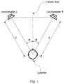
- the listener In order for the summing localization principle to work as intended, it is required that the listener is located between two identical loudspeakers, with equal distance d to both loudspeakers, as illustrated in Fig. 1 .
- Such a symmetrical arrangement of loudspeakers and listener makes it possible for the listener to experience a stereo panorama , or sound image , when a stereo recording is played back through the loudspeakers (that is, when the left and right channels of the recording are played back through the left and right loudspeakers, respectively).
- Various components of the stereo signal are then perceived as sound sources located somewhere between the loudspeakers.
- a mono signal which is equal in left and right channels, will be perceived as coming from a point in the center, straight in front of the listener. This is the so-called phantom center effect.
- the stereo panorama will be incorrectly perceived. For example, if the listener's distance d 1 to the left loudspeaker is shorter than the distance d 2 to the right loudspeaker, then the sound from the left loudspeaker arrives at the listener with a shorter time delay than the sound from the right loudspeaker. Due to the resulting time difference between the left and right loudspeakers, the perceived direction of sound will be heavily biased towards the left loudspeaker, see Fig. 2 .
- the mono component of the stereo signal will in such a scenario no longer be perceived as coming from straight ahead of the listener, but almost solely from the left speaker.
- This collapse of the stereo panorama into the loudspeaker closest to the listener is often referred to as near-side bias.
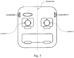
- the most common and well known example of near-side bias occurs when listening to stereo recordings in an automobile, where the listener is situated either to the left or to the right of the center axis.
- a schematic view of the automobile example is shown in Fig. 3 , where Listener 1 sits closer to the left loudspeaker, and Listener 2 sits closer to the right loudspeaker.
- a sound that is intended to be reproduced as coming from a point straight ahead of the listner will be experienced by Listener 1 as coming from the left side, and by Listener 2 as coming from the right side.
- the delay difference between two channels of an audio system, experienced at a spatial position, can be described in the frequency domain by a phase difference function, commonly referred to as inter-loudspeaker differential phase (IDP), taking values between -180 and +180 degrees [5], an example of which is shown in Fig. 5 .
- IDP inter-loudspeaker differential phase
- the IDP allows for a more general description of the time difference between channels, in the sense that it can accomodate for time delays that are frequency dependent.
- the IDP between two audio channels C 1 and C 2 can be determined either by using information from a single point in space, or by using information from a pair of points in space.
- the IDP is obtained by comparing the acoustic transfer function of channel C 1 with that of channel C 2 at the same point.
- the IDP is obtained by comparing the transfer function of channel C 1 in one point with the transfer function of channel C 2 at another point.
- a listener position for which the IDP between two channels C 1 and C 2 is defined, can thus be associated with either one single point or a pair of points in space.
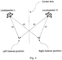
- the two loudspeakers and the listening environment are perfectly symmetrical, and that two listeners are positioned symmetrically on each side of the center axis, as illustrated in Fig. 4 , where the left listener is a distance
- the delay difference between the loudspeaker channels experienced by the two listeners can then be described in the frequency domain by two IDP functions, as illustrated in Fig. 5 .
- the loudspeaker and listener postions were such that
- 35.6 cm.
- IDP functions in this case either increase or decrease linearly with frequency, depending on which side of the center axis the listener is situated (the black line is the phase difference at the left listener position and the grey line is the IDP at the right listener position).
- IDP functions such as those in for example Fig. 5 , may be considered to be continuous even if they appear to contain discontinuous jumps of 360 degrees at some frequencies. This is because of the ambiguity in how phase angles are represented: an angle of +190 degrees is equivalent to an angle of -170 degrees, an angle of 360 degrees is equivalent to an angle of 0 degrees, and so on. It thus makes sense to describe an IDP or a phase curve as for example linearly increasing even if it decreases by a discontinuous jump of 360 degrees at some frequencies.
- the frequency axis can be divided into sequential frequency bands where both listeners experience either an IDP within the interval of ⁇ 90 degrees, or an IDP of more than ⁇ 90 degrees.
- the system At frequencies where the IDP at both listener positions is limited to between ⁇ 90 degrees, the system is said to be predominantly in-phase, and at frequencies where both IDPs are outside of the interval ⁇ 90 degrees, the system is said to be predominantly out-of-phase.
- the near-side bias problem can be corrected to a great extent if a delay is added to the signal path of the loudspeaker closest to the listener, so that the left and right signals arrive at the listener with equal delay, similarly to the situation when the listener is located on the center axis between the loudspeakers.
- phase difference functions often referred to as inter-loudspeker differential phase (IDP) functions
- IDP inter-loudspeker differential phase
- the idea is then to use phase shifting filters which add a phase difference of 180 degrees to the channels, thereby changing the IDP by 180 degrees, in one or several of those frequency bands where the system is predominantly out-of-phase [2, 3, 4, 5].
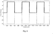
- the adding of a phase difference of 180 degrees to the channels can be accomplished in many different ways; for example by applying a filter that shifts the phase 180 degrees in the left channel and leaving the right channel unprocessed. Alternatively, one can add +90 degrees to one channel and -90 degrees to the other, as suggested in for example [2].
- Fig. 6 The phase responses of such filters are shown in Fig. 6 , where the black line is the desired phase response of the left channel filter, and the grey line is the desired phase response for the right channel filter.
- Fig. 7 the IDP functions that result from applying such filters to the system are shown in Fig. 7 , where the black line is the IDP at the left listener position and the grey line is the IDP at the right listener position. Comparing Fig. 5 and Fig. 7 , one can observe that the system has changed from alternating between predominantly in-phase and out-of-phase in sequential frequency bands, to being predominantly in-phase for all frequencies.
- Yet another object is to provide an audio filter system for performing phase adjustments to at least two audio reproduction channels.
- Yet another object is to provide a computer-program product comprising a computer-readable medium having stored thereon such a computer program.
- Still another object is to provide an apparatus for determining phase adjustment filters for an associated sound generating system.
- Yet another object is to provide an audio system comprising a sound generating system and associated phase adjustment filters.
- a method for determining phase adjustment filters for an associated sound generating system comprising at least two audio reproduction channels C 1 and C 2 , where each of said audio reproduction channels C 1 and C 2 has an input signal and at least one loudspeaker located in a listening environment, wherein said method comprises:
- a system for determining phase adjustment filters for an associated sound generating system comprising at least two audio reproduction channels C 1 and C 2 , where each of said audio reproduction channels C 1 and C 2 has an input signal and at least one loudspeaker located in a listening environment,
- a method for performing phase adjustments to at least two audio reproduction channels C 1 and C 2 where each of said audio reproduction channels C 1 and C 2 has an input signal and at least one loudspeaker located in a listening environment
- said method comprises applying digital filters F 1 ( ⁇ ) and F 2 ( ⁇ ) on the input signals of said audio reproduction channels C 1 and C 2 , respectively, to reduce the IDP between said audio reproduction channels C 1 and C 2 in p listener positions in said listening environment, said IDP being determined based on acoustic transfer functions in said M spatial positions, wherein said digital filters are performing phase adjustments to said audio reproduction channels C 1 and C 2 that counteract said IDP.
- an audio filter system for performing phase adjustments to at least two audio reproduction channels C 1 and C 2 , where each of said audio reproduction channels C 1 and C 2 has an input signal and at least one loudspeaker located in a listening environment, wherein said system is configured to apply digital filters F 1 ( ⁇ ) and F 2 ( ⁇ ) on the input signals of said audio reproduction channels C 1 and C 2 , respectively, to reduce the IDP between said audio reproduction channels C 1 and C 2 in p listener positions in said listening environment, said IDP being determined based on acoustic transfer functions in said M spatial positions, wherein said digital filters are configured to perform phase adjustments to said audio reproduction channels C 1 and C 2 that counteract said IDP.
- a computer program for determining, when executed by a computer, phase adjustment filters for an associated sound generating system comprising at least two audio reproduction channels C 1 and C 2 , where each of said audio reproduction channels C 1 and C 2 has an input signal and at least one loudspeaker located in a listening environment, wherein said computer program comprises instructions, which when executed by said computer, cause said computer to:
- a computer-program product comprising a computer-readable medium having stored thereon such a computer program as described herein.
- an apparatus for determining phase adjustment filters for an associated sound generating system comprising at least two audio reproduction channels C 1 and C 2 , where each of said audio reproduction channels C 1 and C 2 has an input signal and at least one loudspeaker located in a listening environment, wherein said apparatus comprises:
- phase adjustment filter or a pair of phase adjustment filters determined by using the method described herein.
- an audio system comprising a sound generating system and associated phase adjustment filters F 1 ( ⁇ ) and F 2 ( ⁇ ) applied, respectively, to a pair of channels C 1 and C 2 of the system, where said phase adjustment filters F 1 ( ⁇ ) and F 2 ( ⁇ ) are determined by using the method described herein.
- a digital audio signal generated by at least one phase adjustment filter determined by using the method described herein.
- Fig. 16 is a schematic flow diagram illustrating an example of a method for determining phase adjustment filters for an associated sound generating system comprising at least two audio reproduction channels C 1 and C 2 where each of said audio reproduction channels C 1 and C 2 has an input signal and at least one loudspeaker located in a listening environment.
- the method comprises:
- the step of determining phase adjustment filters comprises:
- the step of computing said phase adjustment filters F 1 ( ⁇ ) and F 2 ( ⁇ ) based on said aggregated IDP function comprises:
- the aggregated IDP function is an average IDP function.
- a method for performing phase adjustments to at least two audio reproduction channels C 1 and C 2 where each of said audio reproduction channels C 1 and C 2 has an input signal and at least one loudspeaker located in a listening environment
- said method comprises applying digital filters F 1 ( ⁇ ) and F 2 ( ⁇ ) on the input signals of said audio reproduction channels C 1 and C 2 , respectively, to reduce the IDP between said audio reproduction channels C 1 and C 2 in p listener positions in said listening environment, said IDP being determined based on acoustic transfer functions in said M spatial positions, wherein said digital filters are performing phase adjustments to said audio reproduction channels C 1 and C 2 that counteract said IDP.
- the digital filters are performing said phase adjustments even when the IDP is smaller than ⁇ 90 degrees.
- the IDP is an aggregated IDP of a number of IDPs between said audio reproduction channels, in a frequency interval ⁇ 1 ⁇ ⁇ ⁇ ⁇ 2 , each of which being determined based on information from said acoustic transfer functions at said M spatial positions.
- the aggregated IDP may be an average IDP.
- the improvement is made with respect to one or more listener positions, where the inter-loudspeaker differential phase (IDP) between the channels C 1 and C 2 is nonzero in at least one of the listener positions.
- the object is achieved by performing frequency-dependent phase adjustments to the channels C 1 and C 2 , thereby reducing the overall IDP between the channels, as evaluated using transfer function measurements at M ⁇ 1 positions.
- a listener position is associated either with one single point or with a pair of points in space, selected from a total of M ⁇ 1 measurement points.
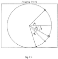
- ⁇ i ( ⁇ ) are then represented as points z i ( ⁇ ) on the unit circle in the complex plane, where the phase angle ⁇ i ( ⁇ ) corresponds to the angle of the point z i ( ⁇ ) from the real axis.
- FIG. 11 that the IDPs ⁇ 1 and ⁇ 2 , when represented as points z 1 and z 2 on the unit circle (marked with black crosses), are located symmetrically with respect to the real axis.
- an aggregated IDP function ⁇ ( ⁇ ) is obtained by using the above described unit-circle representation of the individual IDP functions ⁇ 1 ( ⁇ ), ⁇ 2 ( ⁇ ), ..., ⁇ p ( ⁇ ) to compute an average IDP.
- This averaging operation can be written for example as
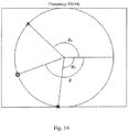
- Fig. 11-Fig. 15 the value of the aggregated IDP function ⁇ , represented with a black circle, was computed using the averaging method described above. It can be seen from Fig. 11 and Fig. 12 that the aggregated IDP function ⁇ in the idealized two-listener case, if computed as above, will take a value of 0° whenever ⁇ 1 and ⁇ 2 are within ⁇ 90° (predominantly in-phase) and a value of 180° whenever ⁇ 1 and ⁇ 2 are outside of ⁇ 90° (predominantly out-of-phase).
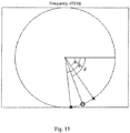
- the IDP between two channels will most likely behave as in Fig. 14 and Fig. 15 at most frequencies. That is, the IDP values ⁇ 1 and ⁇ 2 will not be symmetrical with respect to the real axis, and there is no guarantee that the system will be either predominantly in-phase or predominantly out-of-phase at all listener positions. Thus a simple rule such as adding a phase difference of either 0° or 180° to the channels would not be effective.
- the aggregated IDP function ⁇ ( ⁇ ), computed as described above, is used for defining the phase difference that should be applied to the channels by filters F 1 ( ⁇ ) and F 2 ( ⁇ ) .
- Such a filter design strategy implies that the phase shifting filters will strive to correct the IDP even when the IDP functions are within ⁇ 90° at all listener positions (predominantly in-phase but with a nonzero value of ⁇ ( ⁇ )), as is the case in Fig. 15 .
- phase responses of the filters F 1 ( ⁇ ) and F 2 ( ⁇ ) are determined by a partitioning of the aggregated IDP ⁇ ( ⁇ ) into two phase response curves ⁇ 1 ( ⁇ ) and ⁇ 2 ( ⁇ ) .
- Another option is to select a partitioning such that both ⁇ 1 ( ⁇ ) and ⁇ 2 ( ⁇ ) are monotonically decreasing functions of frequency, in which case the group delay function of both filters F 1 ( ⁇ ) and F 2 ( ⁇ ) will be strictly nonnegative.
- the filters F 1 ( ⁇ ) and F 2 ( ⁇ ) are implemented into the signal chain of a sound reproducing system.
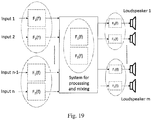
- the location of the filters within the signal chain depends on which parts of the system are considered to represent the pair of channels C 1 and C 2 .
- the channel pair C 1 and C 2 may be associated with two inputs of the system, or they may be associated with two specific loudspeakers and therefore be located at the outputs of the system.
- the channels C 1 and C 2 can be thought of as signal sub-chains inside a signal processing and mixing unit, in which case the filters F 1 ( ⁇ ) and F 2 ( ⁇ ) can be seen as processing steps integrated inside that unit.
- Fig. 19 shows a schematic view of a sound reproducing system, containing some examples of locations in the signal chain where the phase shifting filters F 1 ( ⁇ ) and F 2 ( ⁇ ) can be placed.
- embodiments may be implemented in hardware, or in software for execution by suitable processing circuitry, or a combination thereof.
- At least some of the steps, functions, procedures, modules and/or blocks described herein may be implemented in software such as a computer program for execution by suitable processing circuitry such as one or more processors or processing units.
- processing circuitry includes, but is not limited to, one or more microprocessors, one or more Digital Signal Processors (DSPs), one or more Central Processing Units (CPUs), video acceleration hardware, and/or any suitable programmable logic circuitry such as one or more Field Programmable Gate Arrays (FPGAs), or one or more Programmable Logic Controllers (PLCs).
- DSPs Digital Signal Processors
- CPUs Central Processing Units
- FPGAs Field Programmable Gate Arrays
- PLCs Programmable Logic Controllers
- a system for determining phase adjustment filters for an associated sound generating system comprising at least two audio reproduction channels C 1 and C 2 , where each of said audio reproduction channels C 1 and C 2 has an input signal and at least one loudspeaker located in a listening environment,
- the system is configured to determine p IDP functions ⁇ 1 ( ⁇ ) , ⁇ 2 ( ⁇ ), ... , ⁇ p ( ⁇ ), to determine an aggregated IDP function ⁇ ( ⁇ ), and to compute said phase adjustment filters F 1 ( ⁇ ) and F 2 ( ⁇ ) based on said aggregated IDP function.
- the system is configured to determine phase adj ustment functions ⁇ 1 ( ⁇ ) and ⁇ 2 ( ⁇ ), based on said aggregated IDP function ⁇ ( ⁇ ), and to compute said phase adjustment filters F 1 ( ⁇ ) and F 2 ( ⁇ ) based on said phase adjustment functions ⁇ 1 ( ⁇ ) and ⁇ 2 ( ⁇ ).
- system comprises a processor and a memory, the memory comprising instructions executable by the processor, whereby the processor is operative to determine the phase adjustment filters as described herein.
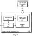
- Fig. 17 is a schematic diagram illustrating an example of a computer-implementation 100 according to an embodiment.
- a computer program 125 135, which is loaded into the memory 120 for execution by processing circuitry including one or more processors 110.
- the processor(s) 110 and memory 120 are interconnected to each other to enable normal software execution.
- An optional input/output device 140 may also be interconnected to the processor(s) 110 and/or the memory 120 to enable input and/or output of relevant data such as input parameter(s) and/or resulting output parameter(s).
- processor should be interpreted in a general sense as any system or device capable of executing program code or computer program instructions to perform a particular processing, determining or computing task.
- the processing circuitry including one or more processors 110 is thus configured to perform, when executing the computer program 125, well-defined processing tasks such as those described herein.
- the processing circuitry does not have to be dedicated to only execute the above-described steps, functions, procedure and/or blocks, but may also execute other tasks.
- a corresponding audio filter system comprising phase adjustment filters as described herein.
- an audio filter system for performing phase adjustments to at least two audio reproduction channels C 1 and C 2 , where each of said audio reproduction channels C 1 and C 2 has an input signal and at least one loudspeaker located in a listening environment, wherein said system is configured to apply digital filters F 1 ( ⁇ ) and F 2 ( ⁇ ) on the input signals of said audio reproduction channels C 1 and C 2 , respectively, to reduce the IDP between said audio reproduction channels C 1 and C 2 in p listener positions in said listening environment, said IDP being determined based on acoustic transfer functions in said M spatial positions, wherein said digital filters are configured to perform phase adjustments to said audio reproduction channels C 1 and C 2 that counteract said IDP.
- a number of computational steps are performed on a separate computer system to produce the filter parameters of the phase adjustment filter(s).
- the calculated filter parameters are then normally downloaded or implemented into a digital filter, for example, realized by a digital signal processing system or customized processing circuitry, which executes the actual filtering.
- the filter design scheme proposed by the invention is preferably implemented as software in the form of program modules, functions or equivalent.
- the relevant steps, functions and actions of the invention are mapped into a computer program, which when being executed by the computer system effectuates the calculations associated with the determination of the phase adjustment filters.
- the computer program used for the design of the audio filter(s) is normally encoded on a computer-readable medium such as a DVD, CD, USB flash drive, or similar structure for distribution to a user/operator, who then may load the program into his/her computer system for subsequent execution.
- the software may even be downloaded from a remote server via the Internet.
- a filter design program implementing a filter design algorithm according to the invention may be stored in a peripheral memory and loaded into a system memory for execution by a processor. Given the relevant input data, such as sound measurements and/or a model representation and other optional configurations, the filter design program determines or calculates the filter parameters of the phase adjustment filter(s).
- the determined filter parameters are then normally transferred from the system memory via an I/O interface to a digital filter or filter system.
- the filter parameters may be stored on a peripheral memory card or memory disk for later distribution to a filter system, which may or may not be remotely located from the filter design system.
- the calculated filter parameters may also be downloaded from a remote location, e.g. via the Internet.
- any conventional microphone unit(s) or similar audio recording equipment may be connected to the computer system. Measurements may also be used to evaluate the performance of the combined system of phase adjustment filters and audio equipment. If the operator is not satisfied with the resulting design, he may initiate a new optimization of the filters based on a modified set of design parameters.
- the filter design system typically has a user interface for allowing user-interaction with the filter designer.
- user-interaction scenarios are possible. For example, the operator may decide that he/she wants to use a specific, customized set of design parameters in the calculation of the filter parameters of the filters. The filter designer then defines the relevant design parameters via the user interface.
- the filter design is performed more or less autonomously with no or only marginal user participation.
- the determination of the filters and the actual implementation of the filters may both be performed in one and the same computer system.
- the filtering may be performed separate from the distribution of the sound signal to the actual place of reproduction.
- the processed signal generated by the phase adjustment filter(s) does not necessarily have to be distributed immediately to and in direct connection with the sound generating system, but may be recorded on a separate medium for later distribution to the sound generating system.
- the digital audio signal could then represent, for example, recorded music that has been adjusted to a particular audio equipment and listening environment. It can also be a processed audio file stored on an Internet server for allowing subsequent downloading or streaming of the file to a remote location over the Internet.
- phase adjustment filter or a pair of phase adjustment filters, determined by using the method described herein.
- an audio system comprising a sound generating system having at least two audio reproduction channels C 1 and C 2 , where each of said audio reproduction channels C 1 and C 2 has an input signal and at least one loudspeaker.
- the audio system further comprises phase adjustment filters F 1 ( ⁇ ) and F 2 ( ⁇ ) applied, respectively, to said audio reproduction channels C 1 and C 2 , wherein the phase adjustment filters are determined by using the method described herein.
- a digital audio signal generated and/or processed by a phase adjustment filter determined by using the method described herein.
- a computer program for determining, when executed by a computer, phase adjustment filters for an associated sound generating system comprising at least two audio reproduction channels C 1 and C 2 , where each of said audio reproduction channels C 1 and C 2 has an input signal and at least one loudspeaker located in a listening environment, wherein said computer program comprises instructions, which when executed by said computer, cause said computer to:
- the proposed technology also provides a carrier comprising the computer program, wherein the carrier is one of an electronic signal, an optical signal, an electromagnetic signal, a magnetic signal, an electric signal, a radio signal, a microwave signal, or a computer-readable storage medium.
- the software or computer program 125; 135 may be realized as a computer program product, which is normally carried or stored on a computer-readable medium 120; 130, in particular a non-volatile medium.
- the computer-readable medium may include one or more removable or non-removable memory devices including, but not limited to a Read-Only Memory (ROM), a Random Access Memory (RAM), a Compact Disc (CD), a Digital Versatile Disc (DVD), a Blu-ray disc, a Universal Serial Bus (USB) memory, a Hard Disk Drive (HDD) storage device, a flash memory, a magnetic tape, or any other conventional memory device.
- the computer program may thus be loaded into the operating memory of a computer or equivalent processing device for execution by the processing circuitry thereof.
- the flow diagram or diagrams presented herein may be regarded as a computer flow diagram or diagrams, when performed by one or more processors.
- a corresponding apparatus may be defined as a group of function modules, where each step performed by the processor corresponds to a function module.
- the function modules are implemented as a computer program running on the processor.
- the computer program residing in memory may thus be organized as appropriate function modules configured to perform, when executed by the processor, at least part of the steps and/or tasks described herein.
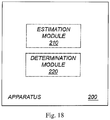
- Fig. 18 is a schematic diagram illustrating an example of an apparatus 200 for determining phase adjustment filters for an associated sound generating system comprising at least two audio reproduction channels C 1 and C 2 , where each of said audio reproduction channels C 1 and C 2 has an input signal and at least one loudspeaker located in a listening environment.
- the apparatus 200 comprises an estimation module 210 for estimating, for each of said audio reproduction channels C 1 and C 2 , an acoustic transfer function at each of M ⁇ 1 spatial positions in said listening environment, based on sound measurements at said spatial positions.
- the apparatus also comprises a determination module 220 for determining, based on said acoustic transfer functions, phase adjustment filters F 1 ( ⁇ ) and F 2 ( ⁇ ) to be applied, respectively, to said audio reproduction channels C 1 and C 2 , to reduce the IDP between said audio reproduction channels C 1 and C 2 in p listener positions.
- module(s) in Fig. 18 predominantly by hardware modules, or alternatively by hardware, with suitable interconnections between relevant modules.
- Particular examples include one or more suitably configured digital signal processors and other known electronic circuits, e.g. discrete logic gates interconnected to perform a specialized function, and/or Application Specific Integrated Circuits (ASICs) as previously mentioned.
- Other examples of usable hardware include input/output (I/O) circuitry and/or circuitry for receiving and/or sending signals.
- I/O input/output
Landscapes
- Physics & Mathematics (AREA)
- Engineering & Computer Science (AREA)
- Acoustics & Sound (AREA)
- Signal Processing (AREA)
- Stereophonic System (AREA)
- Soundproofing, Sound Blocking, And Sound Damping (AREA)
Claims (13)
- Verfahren zum Bestimmen von Phaseneinstellungsfiltern für ein zugeordnetes Klangerzeugungssystem, das mindestens zwei Audiowiedergabekanäle umfasst, wobei jeder der Audiowiedergabekanäle ein Eingangssignal und mindestens einen in einer Hörumgebung angeordneten Lautsprecher aufweist, wobei das Verfahren Folgendes umfasst:- Schätzen (S1), für jeden der Audiowiedergabekanäle, einer akustischen Übertragungsfunktion an jeder der M ≥ 1 Raumpositionen, die auch als Messpunkte bezeichnet werden, in der Hörumgebung basierend auf Schallmessungen an den Raumpositionen; und- Bestimmen (S2), basierend auf den akustischen Übertragungsfunktionen, von Phaseneinstellungsfiltern (F 1(ƒ) und F 2(ƒ)), die auf die jeweiligen Audiowiedergabekanäle angewendet werden sollen, um die Differenzphase zwischen Lautsprechern (inter-loudspeaker differential phase - IDP) zwischen den Audiowiedergabekanälen in p Hörerpositionen zu reduzieren, wobei jede Hörerposition einem einzelnen Punkt oder einem Punktepaar, ausgewählt aus der Gesamtzahl von M ≥ 1 Messpunkten, zugeordnet ist,wobei der Schritt (S2) des Bestimmens von Phaseneinstellungsfiltern (F 1(ƒ) und F 2(ƒ)) Folgendes umfasst:- Bestimmen von p IDP-Funktionen φ 1(ƒ), φ 2(ƒ), ..., φp (ƒ) zwischen den Audiowiedergabekanälen in einem Frequenzintervall ƒ 1 ≤ ƒ ≤ ƒ 2 basierend auf Informationen von den akustischen Übertragungsfunktionen an den M Raumpositionen;- Bestimmen einer aggregierten IDP-Funktion
φ (ƒ) basierend auf den p IDP-Funktionen φ 1(ƒ), φ 2(ƒ), ..., φp (ƒ); und- Berechnen der Phaseneinstellungsfilter (F 1(ƒ) und F 2(ƒ)) basierend auf der aggregierten IDP-Funktion. - Verfahren nach Anspruch 1, wobei der Schritt des Berechnens der Phaseneinstellungsfilter (F 1(ƒ) und F 2(ƒ)) basierend auf der aggregierten IDP-Funktion Folgendes umfasst:- Bestimmen der Phaseneinstellungsfunktionen ψ 1(ƒ) und ψ 2(ƒ) basierend auf der aggregierten IDP-Funktion
φ (ƒ); und- Berechnen der Phaseneinstellungsfilter (F 1(ƒ) und F 2(ƒ)) basierend auf den Phaseneinstellungsfunktionen ψ 1(ƒ) und ψ 2(ƒ). - Verfahren nach Anspruch 1 oder 2, wobei die aggregierte IDP-Funktion eine Mittelwert-IDP-Funktion ist.
- System (100; 200) zum Bestimmen von Phaseneinstellungsfiltern für ein zugeordnetes Klangerzeugungssystem, das mindestens zwei Audiowiedergabekanäle umfasst, wobei jeder der Audiowiedergabekanäle ein Eingangssignal und mindestens einen in einer Hörumgebung angeordneten Lautsprecher aufweist,
wobei das System (100; 200) konfiguriert ist, um für jeden der Audiowiedergabekanäle eine akustische Übertragungsfunktion an jeder der M ≥ 1 Raumpositionen, die auch als Messpunkte bezeichnet werden, in der Hörumgebung basierend auf Schallmessungen an den Raumpositionen zu schätzen; und
wobei das System (100; 200) konfiguriert ist, um basierend auf den akustischen Übertragungsfunktionen Phaseneinstellungsfilter (F 1(ƒ) und F 2(ƒ)) zu bestimmen, die auf die jeweiligen Audiowiedergabekanäle angewendet werden sollen, um die IDP zwischen den Audiowiedergabekanälen in p Hörerpositionen zu reduzieren, wobei jede Hörerposition einem einzelnen Punkt oder einem Punktepaar, ausgewählt aus der Gesamtzahl von M ≥ 1 Messpunkten, zugeordnet ist,
wobei das System (100; 200) konfiguriert ist, um p IDP-Funktionen φ 1(ƒ), φ 2(ƒ), ..., φp (ƒ) zwischen den Audiowiedergabekanälen in einem Frequenzintervall ƒ 1 ≤ ƒ ≤ ƒ 2 basierend auf Informationen von den akustischen Übertragungsfunktionen an den M Raumpositionen zu bestimmen,
wobei das System (100; 200) konfiguriert ist, um eine aggregierte IDP-Funktionφ (ƒ) basierend auf den p IDP-Funktionen φ 1(ƒ), φ 2(ƒ), ..., φp (ƒ) zu bestimmen und
wobei das System (100; 200) konfiguriert ist, um die Phaseneinstellungsfilter (F 1(ƒ) und F 2(ƒ)) basierend auf der aggregierten IDP-Funktion zu berechnen. - System nach Anspruch 4, wobei das System (100; 200) konfiguriert ist, um Phaseneinstellungsfunktionen ψ 1(ƒ) und ψ 2(ƒ) basierend auf der aggregierten IDP-Funktion
φ (ƒ) zu bestimmen; und
wobei das System (100; 200) konfiguriert ist, um die Phaseneinstellungsfilter (F 1(ƒ) und F 2(ƒ)) basierend auf den Phaseneinstellungsfunktionen ψ 1(ƒ) und ψ 2(ƒ) zu berechnen. - Verfahren zum Durchführen von Phaseneinstellungen an mindestens zwei Audiowiedergabekanälen, wobei jeder der Audiowiedergabekanäle ein Eingangssignal und mindestens einen in einer Hörumgebung angeordneten Lautsprecher aufweist, wobei das Verfahren das Anwenden von Digitalfiltern (F 1(ƒ) und F 2(ƒ)) an den jeweiligen Eingangssignalen der Audiowiedergabekanäle umfasst, um die IDP zwischen den Audiowiedergabekanälen in p Hörerpositionen in der Hörumgebung zu reduzieren, wobei die digitalen Filter durch das Verfahren nach einem der Ansprüche 1 bis 3 bestimmt sind.
- Verfahren nach Anspruch 6, wobei die digitalen Filter die Phaseneinstellungen selbst dann durchführen, wenn die IDP kleiner als 90 Grad ist.
- Verfahren nach Anspruch 6 oder 7, wobei die IDP eine aggregierte IDP einer Anzahl von IDP zwischen den Audiowiedergabekanälen in einem Frequenzintervall ƒ 1 ≤ ƒ ≤ ƒ 2 ist, von denen jede basierend auf Informationen von den akustischen Übertragungsfunktionen an den M Raumpositionen bestimmt ist.
- Verfahren nach Anspruch 8, wobei die aggregierte IDP eine Mittelwert-IDP ist.
- Audiofiltersystem zum Durchführen von Phaseneinstellungen an mindestens zwei Audiowiedergabekanälen, wobei jeder der Audiowiedergabekanäle ein Eingangssignal und mindestens einen in einer Hörumgebung angeordneten Lautsprecher aufweist, wobei das System konfiguriert ist, um digitale Filter (F 1(ƒ) und F 2(ƒ)) an den jeweiligen Eingangssignalen der Audiowiedergabekanäle anzuwenden, um die IDP zwischen den Audiowiedergabekanälen in p Hörerpositionen in der Hörumgebung zu reduzieren, wobei die digitalen Filter durch das Verfahren nach einem der Ansprüche 1 bis 3 bestimmt sind.
- Computerprogramm (125; 135) zum Bestimmen, wenn dieses von einem Computer (100) ausgeführt wird, von Phaseneinstellungsfiltern für ein zugeordnetes Klangerzeugungssystem, das mindestens zwei Audiowiedergabekanäle umfasst, wobei jeder der Audiowiedergabekanäle ein Eingangssignal und mindestens einen in einer Hörumgebung angeordneten Lautsprecher aufweist, wobei das Computerprogramm (125; 135) Anweisungen umfasst, die, wenn sie von dem Computer (100) ausgeführt werden, den Computer veranlassen zum:- Schätzen für jeden der Audiowiedergabekanäle einer akustischen Übertragungsfunktion an jeder der M ≥ 1 Raumpositionen, auch als Messpunkte bezeichnet, in der Hörumgebung basierend auf Schallmessungen an den Raumpositionen; und- Bestimmen von Phaseneinstellungsfiltern (F 1(ƒ) und F 2(ƒ)) basierend auf den akustischen Übertragungsfunktionen, die auf die jeweiligen Audiowiedergabekanäle angewendet werden sollen, um die IDP zwischen den Audiowiedergabekanälen in p Hörerpositionen zu reduzieren, wobei jede Hörerposition einem einzelnen Punkt oder einem Punktepaar, ausgewählt aus der Gesamtzahl von M ≥ 1 Messpunkten, zugeordnet ist, durch:- Bestimmen von p IDP-Funktionen φ 1(ƒ), φ 2(ƒ), ..., φp (ƒ) zwischen den Audiowiedergabekanälen in einem Frequenzintervall ƒ 1 ≤ ƒ ≤ ƒ 2 basierend auf Informationen von den akustischen Übertragungsfunktionen an den M Raumpositionen;- Bestimmen einer aggregierten IDP-Funktion
φ (ƒ) basierend auf den p IDP-Funktionen φ 1(ƒ), φ 2(ƒ), ..., φp (ƒ); und- Berechnen der Phaseneinstellungsfilter (F 1(ƒ) und F 2(ƒ)) basierend auf der aggregierten IDP-Funktion. - Computerprogrammprodukt, umfassend ein computerlesbares Medium (120; 130), auf dem ein Computerprogramm (125; 135) nach Anspruch 11 gespeichert ist.
- Audiosystem, umfassend ein Klangerzeugungssystem, das mindestens zwei Audiowiedergabekanälen aufweist, wobei jeder der Audiowiedergabekanäle ein Eingangssignal und mindestens einen Lautsprecher aufweist,
wobei das Audiosystem ein Audiofiltersystem nach Anspruch 10 zum Durchführen von Phaseneinstellungen an den mindestens zwei Audiowiedergabekanälen umfasst.
Applications Claiming Priority (1)
| Application Number | Priority Date | Filing Date | Title |
|---|---|---|---|
| PCT/SE2015/051146 WO2017074232A1 (en) | 2015-10-30 | 2015-10-30 | Reducing the phase difference between audio channels at multiple spatial positions |
Publications (3)
| Publication Number | Publication Date |
|---|---|
| EP3369259A1 EP3369259A1 (de) | 2018-09-05 |
| EP3369259A4 EP3369259A4 (de) | 2019-06-12 |
| EP3369259B1 true EP3369259B1 (de) | 2020-05-27 |
Family
ID=58631875
Family Applications (1)
| Application Number | Title | Priority Date | Filing Date |
|---|---|---|---|
| EP15907398.0A Active EP3369259B1 (de) | 2015-10-30 | 2015-10-30 | Reduzierung der phasendifferenz zwischen audiokanälen bei mehreren raumpositionen |
Country Status (8)
| Country | Link |
|---|---|
| US (1) | US10284995B2 (de) |
| EP (1) | EP3369259B1 (de) |
| JP (1) | JP6661777B2 (de) |
| KR (1) | KR102397627B1 (de) |
| CN (1) | CN108464018B (de) |
| BR (1) | BR112018008699B1 (de) |
| MX (1) | MX384109B (de) |
| WO (1) | WO2017074232A1 (de) |
Families Citing this family (6)
| Publication number | Priority date | Publication date | Assignee | Title |
|---|---|---|---|---|
| FR3091632B1 (fr) * | 2019-01-03 | 2022-03-11 | Parrot Faurecia Automotive Sas | Procédé de détermination d’un filtre de phase pour un système de génération de vibrations perceptibles par un utilisateur comprenant plusieurs transducteurs |
| US10645520B1 (en) * | 2019-06-24 | 2020-05-05 | Facebook Technologies, Llc | Audio system for artificial reality environment |
| CN111787478A (zh) * | 2020-06-23 | 2020-10-16 | 北京小米移动软件有限公司 | 设备控制方法及装置 |
| WO2023009377A1 (en) | 2021-07-28 | 2023-02-02 | Dolby Laboratories Licensing Corporation | A method of processing audio for playback of immersive audio |
| US12154670B2 (en) * | 2022-11-23 | 2024-11-26 | State Farm Mutual Automobile Insurance Company | Home condition alerts based on home sensor data |
| FR3158190B1 (fr) * | 2024-01-09 | 2026-01-02 | Arkamys | Dispositif de traitement de données audio multicanal pour véhicule automobile |
Family Cites Families (16)
| Publication number | Priority date | Publication date | Assignee | Title |
|---|---|---|---|---|
| US5208860A (en) * | 1988-09-02 | 1993-05-04 | Qsound Ltd. | Sound imaging method and apparatus |
| US5046097A (en) * | 1988-09-02 | 1991-09-03 | Qsound Ltd. | Sound imaging process |
| EP1994795B1 (de) * | 2006-03-15 | 2010-07-21 | Dolby Laboratories Licensing Corporation | Abbildung stereophoner klänge |
| CN101401454A (zh) * | 2006-03-15 | 2009-04-01 | 杜比实验室特许公司 | 立体声成像 |
| KR100728043B1 (ko) * | 2006-08-04 | 2007-06-14 | 삼성전자주식회사 | 청취자에게 동상의 음향을 제공하는 방법 및 장치 |
| JP5448451B2 (ja) | 2006-10-19 | 2014-03-19 | パナソニック株式会社 | 音像定位装置、音像定位システム、音像定位方法、プログラム、及び集積回路 |
| FR2918532B1 (fr) * | 2007-07-05 | 2015-04-24 | Arkamys | Procede de traitement sonore d'un signal stereophonique a l'interieur d'un vehicule automobile et vehicule automobile mettant en oeuvre ce procede |
| EP2190221B1 (de) * | 2008-11-20 | 2018-09-12 | Harman Becker Automotive Systems GmbH | Audiosystem |
| CN102197662B (zh) * | 2009-05-18 | 2014-04-23 | 哈曼国际工业有限公司 | 效率优化的音频系统 |
| EP2326108B1 (de) * | 2009-11-02 | 2015-06-03 | Harman Becker Automotive Systems GmbH | Phasenentzerrung für Audiosystem |
| EP2357846A1 (de) * | 2009-12-22 | 2011-08-17 | Harman Becker Automotive Systems GmbH | Gruppenverzögerungsbasierende Bassregelung |
| JP2012186594A (ja) * | 2011-03-04 | 2012-09-27 | Sony Corp | 音響装置、音響調整方法およびプログラム |
| WO2012140764A1 (ja) * | 2011-04-14 | 2012-10-18 | パイオニア株式会社 | 音声信号処理装置、音声信号処理方法及び音声信号処理プログラム |
| MX2014008123A (es) * | 2012-03-22 | 2014-10-17 | Dirac Res Ab | Diseño de controlador de precompensacion de audio usando un conjunto variable de bocinas de soporte. |
| JP5884013B2 (ja) * | 2012-03-26 | 2016-03-15 | パナソニックIpマネジメント株式会社 | 車載用音響再生装置 |
| US10219094B2 (en) * | 2013-07-30 | 2019-02-26 | Thomas Alan Donaldson | Acoustic detection of audio sources to facilitate reproduction of spatial audio spaces |
-
2015
- 2015-10-30 EP EP15907398.0A patent/EP3369259B1/de active Active
- 2015-10-30 MX MX2018005188A patent/MX384109B/es unknown
- 2015-10-30 CN CN201580085673.4A patent/CN108464018B/zh active Active
- 2015-10-30 WO PCT/SE2015/051146 patent/WO2017074232A1/en not_active Ceased
- 2015-10-30 JP JP2018542104A patent/JP6661777B2/ja active Active
- 2015-10-30 US US15/769,526 patent/US10284995B2/en active Active
- 2015-10-30 KR KR1020187013080A patent/KR102397627B1/ko active Active
- 2015-10-30 BR BR112018008699-1A patent/BR112018008699B1/pt not_active IP Right Cessation
Non-Patent Citations (1)
| Title |
|---|
| None * |
Also Published As
| Publication number | Publication date |
|---|---|
| KR20180097516A (ko) | 2018-08-31 |
| MX2018005188A (es) | 2018-07-06 |
| BR112018008699A2 (pt) | 2018-10-30 |
| US10284995B2 (en) | 2019-05-07 |
| MX384109B (es) | 2025-03-14 |
| US20180317037A1 (en) | 2018-11-01 |
| EP3369259A4 (de) | 2019-06-12 |
| CN108464018B (zh) | 2021-02-26 |
| WO2017074232A1 (en) | 2017-05-04 |
| EP3369259A1 (de) | 2018-09-05 |
| JP2018537054A (ja) | 2018-12-13 |
| BR112018008699B1 (pt) | 2022-03-03 |
| KR102397627B1 (ko) | 2022-05-12 |
| JP6661777B2 (ja) | 2020-03-11 |
| CN108464018A (zh) | 2018-08-28 |
Similar Documents
| Publication | Publication Date | Title |
|---|---|---|
| EP3369259B1 (de) | Reduzierung der phasendifferenz zwischen audiokanälen bei mehreren raumpositionen | |
| US10313814B2 (en) | Apparatus and method for sound stage enhancement | |
| US10257640B2 (en) | Device and method for processing a signal in the frequency domain | |
| US6937737B2 (en) | Multi-channel audio surround sound from front located loudspeakers | |
| US9749767B2 (en) | Method and apparatus for reproducing stereophonic sound | |
| RU2685041C2 (ru) | Устройство обработки аудиосигнала и способ фильтрации аудиосигнала | |
| EP2667635B1 (de) | Vorrichtung und Verfahren zur Rauschentfernung | |
| US9462405B2 (en) | Apparatus and method for generating panoramic sound | |
| JP6562572B2 (ja) | ステレオ信号のステレオイメージを修正するためのオーディオ信号処理装置及び方法 | |
| US11388539B2 (en) | Method and device for audio signal processing for binaural virtualization | |
| EP2466918B1 (de) | Audiosystem, Audiosignal-Verarbeitungsvorrichtung und Verfahren sowie Programm | |
| US10681487B2 (en) | Acoustic signal processing apparatus, acoustic signal processing method and program | |
| US9998844B2 (en) | Signal processing device and signal processing method | |
| JP6512767B2 (ja) | 音響処理装置および方法、並びにプログラム | |
| US10721577B2 (en) | Acoustic signal processing apparatus and acoustic signal processing method | |
| JP5034694B2 (ja) | 音像定位処理装置 | |
| JP2020039168A (ja) | サウンドステージ拡張のための機器及び方法 | |
| WO2019106742A1 (ja) | 信号処理装置 |
Legal Events
| Date | Code | Title | Description |
|---|---|---|---|
| STAA | Information on the status of an ep patent application or granted ep patent |
Free format text: STATUS: THE INTERNATIONAL PUBLICATION HAS BEEN MADE |
|
| PUAI | Public reference made under article 153(3) epc to a published international application that has entered the european phase |
Free format text: ORIGINAL CODE: 0009012 |
|
| STAA | Information on the status of an ep patent application or granted ep patent |
Free format text: STATUS: REQUEST FOR EXAMINATION WAS MADE |
|
| 17P | Request for examination filed |
Effective date: 20180530 |
|
| AK | Designated contracting states |
Kind code of ref document: A1 Designated state(s): AL AT BE BG CH CY CZ DE DK EE ES FI FR GB GR HR HU IE IS IT LI LT LU LV MC MK MT NL NO PL PT RO RS SE SI SK SM TR |
|
| AX | Request for extension of the european patent |
Extension state: BA ME |
|
| DAV | Request for validation of the european patent (deleted) | ||
| DAX | Request for extension of the european patent (deleted) | ||
| A4 | Supplementary search report drawn up and despatched |
Effective date: 20190509 |
|
| RIC1 | Information provided on ipc code assigned before grant |
Ipc: H04S 1/00 20060101ALI20190503BHEP Ipc: H04S 7/00 20060101AFI20190503BHEP Ipc: H04S 3/00 20060101ALI20190503BHEP |
|
| GRAP | Despatch of communication of intention to grant a patent |
Free format text: ORIGINAL CODE: EPIDOSNIGR1 |
|
| STAA | Information on the status of an ep patent application or granted ep patent |
Free format text: STATUS: GRANT OF PATENT IS INTENDED |
|
| INTG | Intention to grant announced |
Effective date: 20200318 |
|
| RIN1 | Information on inventor provided before grant (corrected) |
Inventor name: BRAENNMARK, LARS-JOHAN Inventor name: AGREN, JAKOB |
|
| GRAS | Grant fee paid |
Free format text: ORIGINAL CODE: EPIDOSNIGR3 |
|
| GRAA | (expected) grant |
Free format text: ORIGINAL CODE: 0009210 |
|
| STAA | Information on the status of an ep patent application or granted ep patent |
Free format text: STATUS: THE PATENT HAS BEEN GRANTED |
|
| AK | Designated contracting states |
Kind code of ref document: B1 Designated state(s): AL AT BE BG CH CY CZ DE DK EE ES FI FR GB GR HR HU IE IS IT LI LT LU LV MC MK MT NL NO PL PT RO RS SE SI SK SM TR |
|
| RAP1 | Party data changed (applicant data changed or rights of an application transferred) |
Owner name: DIRAC RESEARCH AB |
|
| REG | Reference to a national code |
Ref country code: GB Ref legal event code: FG4D |
|
| REG | Reference to a national code |
Ref country code: CH Ref legal event code: EP |
|
| REG | Reference to a national code |
Ref country code: AT Ref legal event code: REF Ref document number: 1275838 Country of ref document: AT Kind code of ref document: T Effective date: 20200615 |
|
| REG | Reference to a national code |
Ref country code: DE Ref legal event code: R096 Ref document number: 602015053604 Country of ref document: DE |
|
| REG | Reference to a national code |
Ref country code: LT Ref legal event code: MG4D |
|
| PG25 | Lapsed in a contracting state [announced via postgrant information from national office to epo] |
Ref country code: GR Free format text: LAPSE BECAUSE OF FAILURE TO SUBMIT A TRANSLATION OF THE DESCRIPTION OR TO PAY THE FEE WITHIN THE PRESCRIBED TIME-LIMIT Effective date: 20200828 Ref country code: FI Free format text: LAPSE BECAUSE OF FAILURE TO SUBMIT A TRANSLATION OF THE DESCRIPTION OR TO PAY THE FEE WITHIN THE PRESCRIBED TIME-LIMIT Effective date: 20200527 Ref country code: NO Free format text: LAPSE BECAUSE OF FAILURE TO SUBMIT A TRANSLATION OF THE DESCRIPTION OR TO PAY THE FEE WITHIN THE PRESCRIBED TIME-LIMIT Effective date: 20200827 Ref country code: LT Free format text: LAPSE BECAUSE OF FAILURE TO SUBMIT A TRANSLATION OF THE DESCRIPTION OR TO PAY THE FEE WITHIN THE PRESCRIBED TIME-LIMIT Effective date: 20200527 Ref country code: PT Free format text: LAPSE BECAUSE OF FAILURE TO SUBMIT A TRANSLATION OF THE DESCRIPTION OR TO PAY THE FEE WITHIN THE PRESCRIBED TIME-LIMIT Effective date: 20200928 Ref country code: IS Free format text: LAPSE BECAUSE OF FAILURE TO SUBMIT A TRANSLATION OF THE DESCRIPTION OR TO PAY THE FEE WITHIN THE PRESCRIBED TIME-LIMIT Effective date: 20200927 Ref country code: SE Free format text: LAPSE BECAUSE OF FAILURE TO SUBMIT A TRANSLATION OF THE DESCRIPTION OR TO PAY THE FEE WITHIN THE PRESCRIBED TIME-LIMIT Effective date: 20200527 |
|
| REG | Reference to a national code |
Ref country code: NL Ref legal event code: MP Effective date: 20200527 |
|
| PG25 | Lapsed in a contracting state [announced via postgrant information from national office to epo] |
Ref country code: RS Free format text: LAPSE BECAUSE OF FAILURE TO SUBMIT A TRANSLATION OF THE DESCRIPTION OR TO PAY THE FEE WITHIN THE PRESCRIBED TIME-LIMIT Effective date: 20200527 Ref country code: BG Free format text: LAPSE BECAUSE OF FAILURE TO SUBMIT A TRANSLATION OF THE DESCRIPTION OR TO PAY THE FEE WITHIN THE PRESCRIBED TIME-LIMIT Effective date: 20200827 Ref country code: LV Free format text: LAPSE BECAUSE OF FAILURE TO SUBMIT A TRANSLATION OF THE DESCRIPTION OR TO PAY THE FEE WITHIN THE PRESCRIBED TIME-LIMIT Effective date: 20200527 Ref country code: HR Free format text: LAPSE BECAUSE OF FAILURE TO SUBMIT A TRANSLATION OF THE DESCRIPTION OR TO PAY THE FEE WITHIN THE PRESCRIBED TIME-LIMIT Effective date: 20200527 |
|
| REG | Reference to a national code |
Ref country code: AT Ref legal event code: MK05 Ref document number: 1275838 Country of ref document: AT Kind code of ref document: T Effective date: 20200527 |
|
| PG25 | Lapsed in a contracting state [announced via postgrant information from national office to epo] |
Ref country code: NL Free format text: LAPSE BECAUSE OF FAILURE TO SUBMIT A TRANSLATION OF THE DESCRIPTION OR TO PAY THE FEE WITHIN THE PRESCRIBED TIME-LIMIT Effective date: 20200527 Ref country code: AL Free format text: LAPSE BECAUSE OF FAILURE TO SUBMIT A TRANSLATION OF THE DESCRIPTION OR TO PAY THE FEE WITHIN THE PRESCRIBED TIME-LIMIT Effective date: 20200527 |
|
| PG25 | Lapsed in a contracting state [announced via postgrant information from national office to epo] |
Ref country code: ES Free format text: LAPSE BECAUSE OF FAILURE TO SUBMIT A TRANSLATION OF THE DESCRIPTION OR TO PAY THE FEE WITHIN THE PRESCRIBED TIME-LIMIT Effective date: 20200527 Ref country code: DK Free format text: LAPSE BECAUSE OF FAILURE TO SUBMIT A TRANSLATION OF THE DESCRIPTION OR TO PAY THE FEE WITHIN THE PRESCRIBED TIME-LIMIT Effective date: 20200527 Ref country code: AT Free format text: LAPSE BECAUSE OF FAILURE TO SUBMIT A TRANSLATION OF THE DESCRIPTION OR TO PAY THE FEE WITHIN THE PRESCRIBED TIME-LIMIT Effective date: 20200527 Ref country code: CZ Free format text: LAPSE BECAUSE OF FAILURE TO SUBMIT A TRANSLATION OF THE DESCRIPTION OR TO PAY THE FEE WITHIN THE PRESCRIBED TIME-LIMIT Effective date: 20200527 Ref country code: RO Free format text: LAPSE BECAUSE OF FAILURE TO SUBMIT A TRANSLATION OF THE DESCRIPTION OR TO PAY THE FEE WITHIN THE PRESCRIBED TIME-LIMIT Effective date: 20200527 Ref country code: IT Free format text: LAPSE BECAUSE OF FAILURE TO SUBMIT A TRANSLATION OF THE DESCRIPTION OR TO PAY THE FEE WITHIN THE PRESCRIBED TIME-LIMIT Effective date: 20200527 Ref country code: EE Free format text: LAPSE BECAUSE OF FAILURE TO SUBMIT A TRANSLATION OF THE DESCRIPTION OR TO PAY THE FEE WITHIN THE PRESCRIBED TIME-LIMIT Effective date: 20200527 Ref country code: SM Free format text: LAPSE BECAUSE OF FAILURE TO SUBMIT A TRANSLATION OF THE DESCRIPTION OR TO PAY THE FEE WITHIN THE PRESCRIBED TIME-LIMIT Effective date: 20200527 |
|
| PG25 | Lapsed in a contracting state [announced via postgrant information from national office to epo] |
Ref country code: SK Free format text: LAPSE BECAUSE OF FAILURE TO SUBMIT A TRANSLATION OF THE DESCRIPTION OR TO PAY THE FEE WITHIN THE PRESCRIBED TIME-LIMIT Effective date: 20200527 Ref country code: PL Free format text: LAPSE BECAUSE OF FAILURE TO SUBMIT A TRANSLATION OF THE DESCRIPTION OR TO PAY THE FEE WITHIN THE PRESCRIBED TIME-LIMIT Effective date: 20200527 |
|
| REG | Reference to a national code |
Ref country code: DE Ref legal event code: R097 Ref document number: 602015053604 Country of ref document: DE |
|
| PLBE | No opposition filed within time limit |
Free format text: ORIGINAL CODE: 0009261 |
|
| STAA | Information on the status of an ep patent application or granted ep patent |
Free format text: STATUS: NO OPPOSITION FILED WITHIN TIME LIMIT |
|
| 26N | No opposition filed |
Effective date: 20210302 |
|
| PG25 | Lapsed in a contracting state [announced via postgrant information from national office to epo] |
Ref country code: SI Free format text: LAPSE BECAUSE OF FAILURE TO SUBMIT A TRANSLATION OF THE DESCRIPTION OR TO PAY THE FEE WITHIN THE PRESCRIBED TIME-LIMIT Effective date: 20200527 |
|
| REG | Reference to a national code |
Ref country code: CH Ref legal event code: PL |
|
| PG25 | Lapsed in a contracting state [announced via postgrant information from national office to epo] |
Ref country code: MC Free format text: LAPSE BECAUSE OF FAILURE TO SUBMIT A TRANSLATION OF THE DESCRIPTION OR TO PAY THE FEE WITHIN THE PRESCRIBED TIME-LIMIT Effective date: 20200527 Ref country code: LU Free format text: LAPSE BECAUSE OF NON-PAYMENT OF DUE FEES Effective date: 20201030 |
|
| REG | Reference to a national code |
Ref country code: BE Ref legal event code: MM Effective date: 20201031 |
|
| PG25 | Lapsed in a contracting state [announced via postgrant information from national office to epo] |
Ref country code: CH Free format text: LAPSE BECAUSE OF NON-PAYMENT OF DUE FEES Effective date: 20201031 Ref country code: BE Free format text: LAPSE BECAUSE OF NON-PAYMENT OF DUE FEES Effective date: 20201031 Ref country code: LI Free format text: LAPSE BECAUSE OF NON-PAYMENT OF DUE FEES Effective date: 20201031 |
|
| PG25 | Lapsed in a contracting state [announced via postgrant information from national office to epo] |
Ref country code: IE Free format text: LAPSE BECAUSE OF NON-PAYMENT OF DUE FEES Effective date: 20201030 |
|
| PG25 | Lapsed in a contracting state [announced via postgrant information from national office to epo] |
Ref country code: TR Free format text: LAPSE BECAUSE OF FAILURE TO SUBMIT A TRANSLATION OF THE DESCRIPTION OR TO PAY THE FEE WITHIN THE PRESCRIBED TIME-LIMIT Effective date: 20200527 Ref country code: MT Free format text: LAPSE BECAUSE OF FAILURE TO SUBMIT A TRANSLATION OF THE DESCRIPTION OR TO PAY THE FEE WITHIN THE PRESCRIBED TIME-LIMIT Effective date: 20200527 Ref country code: CY Free format text: LAPSE BECAUSE OF FAILURE TO SUBMIT A TRANSLATION OF THE DESCRIPTION OR TO PAY THE FEE WITHIN THE PRESCRIBED TIME-LIMIT Effective date: 20200527 |
|
| PG25 | Lapsed in a contracting state [announced via postgrant information from national office to epo] |
Ref country code: MK Free format text: LAPSE BECAUSE OF FAILURE TO SUBMIT A TRANSLATION OF THE DESCRIPTION OR TO PAY THE FEE WITHIN THE PRESCRIBED TIME-LIMIT Effective date: 20200527 |
|
| PGFP | Annual fee paid to national office [announced via postgrant information from national office to epo] |
Ref country code: GB Payment date: 20250918 Year of fee payment: 11 |
|
| PGFP | Annual fee paid to national office [announced via postgrant information from national office to epo] |
Ref country code: FR Payment date: 20250915 Year of fee payment: 11 |
|
| PGFP | Annual fee paid to national office [announced via postgrant information from national office to epo] |
Ref country code: DE Payment date: 20250917 Year of fee payment: 11 |