EP3368909B1 - Verfahren, werkzeuge und werkzeuganordnungen für biomolekulare analyse unter verwendung von mikroarrays - Google Patents
Verfahren, werkzeuge und werkzeuganordnungen für biomolekulare analyse unter verwendung von mikroarrays Download PDFInfo
- Publication number
- EP3368909B1 EP3368909B1 EP16860594.7A EP16860594A EP3368909B1 EP 3368909 B1 EP3368909 B1 EP 3368909B1 EP 16860594 A EP16860594 A EP 16860594A EP 3368909 B1 EP3368909 B1 EP 3368909B1
- Authority
- EP
- European Patent Office
- Prior art keywords
- pillar
- clamps
- plate
- pillar plate
- microarrays
- Prior art date
- Legal status (The legal status is an assumption and is not a legal conclusion. Google has not performed a legal analysis and makes no representation as to the accuracy of the status listed.)
- Active
Links
- 238000002493 microarray Methods 0.000 title claims description 187
- 238000000034 method Methods 0.000 title claims description 45
- 230000000712 assembly Effects 0.000 title description 10
- 238000000429 assembly Methods 0.000 title description 10
- 238000004458 analytical method Methods 0.000 title description 6
- 238000003556 assay Methods 0.000 claims description 40
- 239000004593 Epoxy Substances 0.000 claims description 12
- 230000007246 mechanism Effects 0.000 claims description 10
- 239000000853 adhesive Substances 0.000 claims description 8
- 230000001070 adhesive effect Effects 0.000 claims description 8
- 239000003292 glue Substances 0.000 claims description 8
- 108090000765 processed proteins & peptides Proteins 0.000 description 80
- 238000010168 coupling process Methods 0.000 description 55
- 230000008878 coupling Effects 0.000 description 54
- 238000005859 coupling reaction Methods 0.000 description 54
- 239000000243 solution Substances 0.000 description 52
- 150000001413 amino acids Chemical class 0.000 description 43
- 239000000523 sample Substances 0.000 description 38
- 239000000758 substrate Substances 0.000 description 37
- 102000004196 processed proteins & peptides Human genes 0.000 description 33
- 108090000623 proteins and genes Proteins 0.000 description 30
- 102000004169 proteins and genes Human genes 0.000 description 28
- 229920002120 photoresistant polymer Polymers 0.000 description 17
- 239000000090 biomarker Substances 0.000 description 15
- 229920001184 polypeptide Polymers 0.000 description 15
- 230000015572 biosynthetic process Effects 0.000 description 14
- 238000003786 synthesis reaction Methods 0.000 description 14
- 125000003277 amino group Chemical group 0.000 description 12
- 108091007433 antigens Proteins 0.000 description 12
- 102000036639 antigens Human genes 0.000 description 12
- 125000002843 carboxylic acid group Chemical group 0.000 description 12
- 239000000203 mixture Substances 0.000 description 12
- 239000000427 antigen Substances 0.000 description 11
- 238000009739 binding Methods 0.000 description 11
- 230000027455 binding Effects 0.000 description 10
- 238000009472 formulation Methods 0.000 description 10
- 230000008569 process Effects 0.000 description 10
- 235000012431 wafers Nutrition 0.000 description 9
- XLYOFNOQVPJJNP-UHFFFAOYSA-N water Substances O XLYOFNOQVPJJNP-UHFFFAOYSA-N 0.000 description 9
- 150000001735 carboxylic acids Chemical class 0.000 description 8
- 238000006243 chemical reaction Methods 0.000 description 8
- 108020004414 DNA Proteins 0.000 description 7
- 102000053602 DNA Human genes 0.000 description 7
- 201000010099 disease Diseases 0.000 description 7
- 208000037265 diseases, disorders, signs and symptoms Diseases 0.000 description 7
- 238000012360 testing method Methods 0.000 description 7
- 238000011282 treatment Methods 0.000 description 7
- WFDIJRYMOXRFFG-UHFFFAOYSA-N Acetic anhydride Chemical compound CC(=O)OC(C)=O WFDIJRYMOXRFFG-UHFFFAOYSA-N 0.000 description 6
- 102000004190 Enzymes Human genes 0.000 description 6
- 108090000790 Enzymes Proteins 0.000 description 6
- KFZMGEQAYNKOFK-UHFFFAOYSA-N Isopropanol Chemical compound CC(C)O KFZMGEQAYNKOFK-UHFFFAOYSA-N 0.000 description 6
- ZMXDDKWLCZADIW-UHFFFAOYSA-N N,N-Dimethylformamide Chemical compound CN(C)C=O ZMXDDKWLCZADIW-UHFFFAOYSA-N 0.000 description 6
- 150000001875 compounds Chemical class 0.000 description 6
- 238000004519 manufacturing process Methods 0.000 description 6
- 229920000642 polymer Polymers 0.000 description 6
- 125000006239 protecting group Chemical group 0.000 description 6
- 229920002477 rna polymer Polymers 0.000 description 6
- 239000000126 substance Substances 0.000 description 6
- 230000001225 therapeutic effect Effects 0.000 description 6
- 229910001868 water Inorganic materials 0.000 description 6
- XUIMIQQOPSSXEZ-UHFFFAOYSA-N Silicon Chemical compound [Si] XUIMIQQOPSSXEZ-UHFFFAOYSA-N 0.000 description 5
- 230000004913 activation Effects 0.000 description 5
- 210000004027 cell Anatomy 0.000 description 5
- 239000003446 ligand Substances 0.000 description 5
- 239000010703 silicon Substances 0.000 description 5
- 229910052710 silicon Inorganic materials 0.000 description 5
- -1 tert-Butyloxycarbonyl (boc) group Chemical group 0.000 description 5
- 238000005406 washing Methods 0.000 description 5
- LMDZBCPBFSXMTL-UHFFFAOYSA-N 1-ethyl-3-(3-dimethylaminopropyl)carbodiimide Chemical compound CCN=C=NCCCN(C)C LMDZBCPBFSXMTL-UHFFFAOYSA-N 0.000 description 4
- CSCPPACGZOOCGX-UHFFFAOYSA-N Acetone Chemical compound CC(C)=O CSCPPACGZOOCGX-UHFFFAOYSA-N 0.000 description 4
- 230000004568 DNA-binding Effects 0.000 description 4
- 108091034117 Oligonucleotide Proteins 0.000 description 4
- JLCPHMBAVCMARE-UHFFFAOYSA-N [3-[[3-[[3-[[3-[[3-[[3-[[3-[[3-[[3-[[3-[[3-[[5-(2-amino-6-oxo-1H-purin-9-yl)-3-[[3-[[3-[[3-[[3-[[3-[[5-(2-amino-6-oxo-1H-purin-9-yl)-3-[[5-(2-amino-6-oxo-1H-purin-9-yl)-3-hydroxyoxolan-2-yl]methoxy-hydroxyphosphoryl]oxyoxolan-2-yl]methoxy-hydroxyphosphoryl]oxy-5-(5-methyl-2,4-dioxopyrimidin-1-yl)oxolan-2-yl]methoxy-hydroxyphosphoryl]oxy-5-(6-aminopurin-9-yl)oxolan-2-yl]methoxy-hydroxyphosphoryl]oxy-5-(6-aminopurin-9-yl)oxolan-2-yl]methoxy-hydroxyphosphoryl]oxy-5-(6-aminopurin-9-yl)oxolan-2-yl]methoxy-hydroxyphosphoryl]oxy-5-(6-aminopurin-9-yl)oxolan-2-yl]methoxy-hydroxyphosphoryl]oxyoxolan-2-yl]methoxy-hydroxyphosphoryl]oxy-5-(5-methyl-2,4-dioxopyrimidin-1-yl)oxolan-2-yl]methoxy-hydroxyphosphoryl]oxy-5-(4-amino-2-oxopyrimidin-1-yl)oxolan-2-yl]methoxy-hydroxyphosphoryl]oxy-5-(5-methyl-2,4-dioxopyrimidin-1-yl)oxolan-2-yl]methoxy-hydroxyphosphoryl]oxy-5-(5-methyl-2,4-dioxopyrimidin-1-yl)oxolan-2-yl]methoxy-hydroxyphosphoryl]oxy-5-(6-aminopurin-9-yl)oxolan-2-yl]methoxy-hydroxyphosphoryl]oxy-5-(6-aminopurin-9-yl)oxolan-2-yl]methoxy-hydroxyphosphoryl]oxy-5-(4-amino-2-oxopyrimidin-1-yl)oxolan-2-yl]methoxy-hydroxyphosphoryl]oxy-5-(4-amino-2-oxopyrimidin-1-yl)oxolan-2-yl]methoxy-hydroxyphosphoryl]oxy-5-(4-amino-2-oxopyrimidin-1-yl)oxolan-2-yl]methoxy-hydroxyphosphoryl]oxy-5-(6-aminopurin-9-yl)oxolan-2-yl]methoxy-hydroxyphosphoryl]oxy-5-(4-amino-2-oxopyrimidin-1-yl)oxolan-2-yl]methyl [5-(6-aminopurin-9-yl)-2-(hydroxymethyl)oxolan-3-yl] hydrogen phosphate Polymers Cc1cn(C2CC(OP(O)(=O)OCC3OC(CC3OP(O)(=O)OCC3OC(CC3O)n3cnc4c3nc(N)[nH]c4=O)n3cnc4c3nc(N)[nH]c4=O)C(COP(O)(=O)OC3CC(OC3COP(O)(=O)OC3CC(OC3COP(O)(=O)OC3CC(OC3COP(O)(=O)OC3CC(OC3COP(O)(=O)OC3CC(OC3COP(O)(=O)OC3CC(OC3COP(O)(=O)OC3CC(OC3COP(O)(=O)OC3CC(OC3COP(O)(=O)OC3CC(OC3COP(O)(=O)OC3CC(OC3COP(O)(=O)OC3CC(OC3COP(O)(=O)OC3CC(OC3COP(O)(=O)OC3CC(OC3COP(O)(=O)OC3CC(OC3COP(O)(=O)OC3CC(OC3COP(O)(=O)OC3CC(OC3COP(O)(=O)OC3CC(OC3CO)n3cnc4c(N)ncnc34)n3ccc(N)nc3=O)n3cnc4c(N)ncnc34)n3ccc(N)nc3=O)n3ccc(N)nc3=O)n3ccc(N)nc3=O)n3cnc4c(N)ncnc34)n3cnc4c(N)ncnc34)n3cc(C)c(=O)[nH]c3=O)n3cc(C)c(=O)[nH]c3=O)n3ccc(N)nc3=O)n3cc(C)c(=O)[nH]c3=O)n3cnc4c3nc(N)[nH]c4=O)n3cnc4c(N)ncnc34)n3cnc4c(N)ncnc34)n3cnc4c(N)ncnc34)n3cnc4c(N)ncnc34)O2)c(=O)[nH]c1=O JLCPHMBAVCMARE-UHFFFAOYSA-N 0.000 description 4
- 230000000890 antigenic effect Effects 0.000 description 4
- 239000012867 bioactive agent Substances 0.000 description 4
- 239000000463 material Substances 0.000 description 4
- 239000002773 nucleotide Substances 0.000 description 4
- 125000003729 nucleotide group Chemical group 0.000 description 4
- 239000002904 solvent Substances 0.000 description 4
- 108060003951 Immunoglobulin Proteins 0.000 description 3
- OKKJLVBELUTLKV-UHFFFAOYSA-N Methanol Chemical compound OC OKKJLVBELUTLKV-UHFFFAOYSA-N 0.000 description 3
- JGFZNNIVVJXRND-UHFFFAOYSA-N N,N-Diisopropylethylamine (DIPEA) Chemical compound CCN(C(C)C)C(C)C JGFZNNIVVJXRND-UHFFFAOYSA-N 0.000 description 3
- 108091093037 Peptide nucleic acid Proteins 0.000 description 3
- 239000012491 analyte Substances 0.000 description 3
- 230000008901 benefit Effects 0.000 description 3
- 125000003178 carboxy group Chemical group [H]OC(*)=O 0.000 description 3
- 238000006073 displacement reaction Methods 0.000 description 3
- 239000003814 drug Substances 0.000 description 3
- 230000028993 immune response Effects 0.000 description 3
- 210000000987 immune system Anatomy 0.000 description 3
- 102000018358 immunoglobulin Human genes 0.000 description 3
- 239000007788 liquid Substances 0.000 description 3
- 102000039446 nucleic acids Human genes 0.000 description 3
- 108020004707 nucleic acids Proteins 0.000 description 3
- 150000007523 nucleic acids Chemical class 0.000 description 3
- 238000011160 research Methods 0.000 description 3
- 230000004044 response Effects 0.000 description 3
- 235000000346 sugar Nutrition 0.000 description 3
- 150000008163 sugars Chemical class 0.000 description 3
- 210000001519 tissue Anatomy 0.000 description 3
- HZAXFHJVJLSVMW-UHFFFAOYSA-N 2-Aminoethan-1-ol Chemical group NCCO HZAXFHJVJLSVMW-UHFFFAOYSA-N 0.000 description 2
- IJGRMHOSHXDMSA-UHFFFAOYSA-N Atomic nitrogen Chemical compound N#N IJGRMHOSHXDMSA-UHFFFAOYSA-N 0.000 description 2
- 241000124008 Mammalia Species 0.000 description 2
- SECXISVLQFMRJM-UHFFFAOYSA-N N-Methylpyrrolidone Chemical compound CN1CCCC1=O SECXISVLQFMRJM-UHFFFAOYSA-N 0.000 description 2
- 108091005804 Peptidases Proteins 0.000 description 2
- 108091000080 Phosphotransferase Proteins 0.000 description 2
- 239000004365 Protease Substances 0.000 description 2
- 210000004381 amniotic fluid Anatomy 0.000 description 2
- 210000003567 ascitic fluid Anatomy 0.000 description 2
- 239000012472 biological sample Substances 0.000 description 2
- 150000001732 carboxylic acid derivatives Chemical class 0.000 description 2
- 239000003153 chemical reaction reagent Substances 0.000 description 2
- 238000001212 derivatisation Methods 0.000 description 2
- 238000001514 detection method Methods 0.000 description 2
- UQLDLKMNUJERMK-UHFFFAOYSA-L di(octadecanoyloxy)lead Chemical compound [Pb+2].CCCCCCCCCCCCCCCCCC([O-])=O.CCCCCCCCCCCCCCCCCC([O-])=O UQLDLKMNUJERMK-UHFFFAOYSA-L 0.000 description 2
- 238000009792 diffusion process Methods 0.000 description 2
- 229940079593 drug Drugs 0.000 description 2
- 239000003925 fat Substances 0.000 description 2
- 239000011521 glass Substances 0.000 description 2
- 230000001900 immune effect Effects 0.000 description 2
- 238000011065 in-situ storage Methods 0.000 description 2
- 238000011534 incubation Methods 0.000 description 2
- 230000003993 interaction Effects 0.000 description 2
- 238000011835 investigation Methods 0.000 description 2
- 150000002500 ions Chemical class 0.000 description 2
- 150000002632 lipids Chemical class 0.000 description 2
- 230000035772 mutation Effects 0.000 description 2
- 239000003960 organic solvent Substances 0.000 description 2
- 102000020233 phosphotransferase Human genes 0.000 description 2
- 229920003023 plastic Polymers 0.000 description 2
- 239000004033 plastic Substances 0.000 description 2
- 210000004910 pleural fluid Anatomy 0.000 description 2
- 238000000159 protein binding assay Methods 0.000 description 2
- 230000005855 radiation Effects 0.000 description 2
- 150000003839 salts Chemical class 0.000 description 2
- 239000007787 solid Substances 0.000 description 2
- KZNICNPSHKQLFF-UHFFFAOYSA-N succinimide Chemical compound O=C1CCC(=O)N1 KZNICNPSHKQLFF-UHFFFAOYSA-N 0.000 description 2
- WGTYBPLFGIVFAS-UHFFFAOYSA-M tetramethylammonium hydroxide Chemical compound [OH-].C[N+](C)(C)C WGTYBPLFGIVFAS-UHFFFAOYSA-M 0.000 description 2
- 210000002700 urine Anatomy 0.000 description 2
- 229960005486 vaccine Drugs 0.000 description 2
- 229940125575 vaccine candidate Drugs 0.000 description 2
- 238000011179 visual inspection Methods 0.000 description 2
- 125000003088 (fluoren-9-ylmethoxy)carbonyl group Chemical group 0.000 description 1
- BDNKZNFMNDZQMI-UHFFFAOYSA-N 1,3-diisopropylcarbodiimide Chemical compound CC(C)N=C=NC(C)C BDNKZNFMNDZQMI-UHFFFAOYSA-N 0.000 description 1
- ASOKPJOREAFHNY-UHFFFAOYSA-N 1-Hydroxybenzotriazole Chemical compound C1=CC=C2N(O)N=NC2=C1 ASOKPJOREAFHNY-UHFFFAOYSA-N 0.000 description 1
- 108091023037 Aptamer Proteins 0.000 description 1
- 241000894006 Bacteria Species 0.000 description 1
- 208000035143 Bacterial infection Diseases 0.000 description 1
- 241000283690 Bos taurus Species 0.000 description 1
- 241000282472 Canis lupus familiaris Species 0.000 description 1
- 102000000844 Cell Surface Receptors Human genes 0.000 description 1
- 108010001857 Cell Surface Receptors Proteins 0.000 description 1
- 241000195493 Cryptophyta Species 0.000 description 1
- 150000008574 D-amino acids Chemical class 0.000 description 1
- 108010016626 Dipeptides Proteins 0.000 description 1
- 238000002965 ELISA Methods 0.000 description 1
- 241000282326 Felis catus Species 0.000 description 1
- 150000008575 L-amino acids Chemical class 0.000 description 1
- 102000003960 Ligases Human genes 0.000 description 1
- 108090000364 Ligases Proteins 0.000 description 1
- OFOBLEOULBTSOW-UHFFFAOYSA-N Malonic acid Chemical compound OC(=O)CC(O)=O OFOBLEOULBTSOW-UHFFFAOYSA-N 0.000 description 1
- NQTADLQHYWFPDB-UHFFFAOYSA-N N-Hydroxysuccinimide Chemical compound ON1C(=O)CCC1=O NQTADLQHYWFPDB-UHFFFAOYSA-N 0.000 description 1
- 102000015636 Oligopeptides Human genes 0.000 description 1
- 108010038807 Oligopeptides Proteins 0.000 description 1
- 102000043276 Oncogene Human genes 0.000 description 1
- 108700020796 Oncogene Proteins 0.000 description 1
- 241001494479 Pecora Species 0.000 description 1
- 102000035195 Peptidases Human genes 0.000 description 1
- 102000045595 Phosphoprotein Phosphatases Human genes 0.000 description 1
- 108700019535 Phosphoprotein Phosphatases Proteins 0.000 description 1
- 239000004372 Polyvinyl alcohol Substances 0.000 description 1
- 206010036790 Productive cough Diseases 0.000 description 1
- 102100037486 Reverse transcriptase/ribonuclease H Human genes 0.000 description 1
- 240000004808 Saccharomyces cerevisiae Species 0.000 description 1
- 241000282887 Suidae Species 0.000 description 1
- 108091008874 T cell receptors Proteins 0.000 description 1
- 102000016266 T-Cell Antigen Receptors Human genes 0.000 description 1
- 102000040945 Transcription factor Human genes 0.000 description 1
- 108091023040 Transcription factor Proteins 0.000 description 1
- 241000700605 Viruses Species 0.000 description 1
- 230000021736 acetylation Effects 0.000 description 1
- 238000006640 acetylation reaction Methods 0.000 description 1
- 210000005006 adaptive immune system Anatomy 0.000 description 1
- 150000001408 amides Chemical class 0.000 description 1
- 150000001412 amines Chemical class 0.000 description 1
- 125000000539 amino acid group Chemical group 0.000 description 1
- 230000003321 amplification Effects 0.000 description 1
- 230000000845 anti-microbial effect Effects 0.000 description 1
- 239000004599 antimicrobial Substances 0.000 description 1
- 238000003491 array Methods 0.000 description 1
- 210000003719 b-lymphocyte Anatomy 0.000 description 1
- 208000022362 bacterial infectious disease Diseases 0.000 description 1
- 210000000941 bile Anatomy 0.000 description 1
- 238000010876 biochemical test Methods 0.000 description 1
- 210000004369 blood Anatomy 0.000 description 1
- 239000008280 blood Substances 0.000 description 1
- 210000000601 blood cell Anatomy 0.000 description 1
- 210000001124 body fluid Anatomy 0.000 description 1
- 239000007853 buffer solution Substances 0.000 description 1
- 239000006227 byproduct Substances 0.000 description 1
- 150000001718 carbodiimides Chemical class 0.000 description 1
- 125000002915 carbonyl group Chemical group [*:2]C([*:1])=O 0.000 description 1
- 230000019522 cellular metabolic process Effects 0.000 description 1
- 210000001175 cerebrospinal fluid Anatomy 0.000 description 1
- 210000002939 cerumen Anatomy 0.000 description 1
- 210000003756 cervix mucus Anatomy 0.000 description 1
- 230000008859 change Effects 0.000 description 1
- 238000007385 chemical modification Methods 0.000 description 1
- 239000003795 chemical substances by application Substances 0.000 description 1
- 238000002512 chemotherapy Methods 0.000 description 1
- 210000001268 chyle Anatomy 0.000 description 1
- 239000011248 coating agent Substances 0.000 description 1
- 238000000576 coating method Methods 0.000 description 1
- 238000006482 condensation reaction Methods 0.000 description 1
- 239000013078 crystal Substances 0.000 description 1
- 210000004292 cytoskeleton Anatomy 0.000 description 1
- 230000007423 decrease Effects 0.000 description 1
- 230000003247 decreasing effect Effects 0.000 description 1
- 230000018044 dehydration Effects 0.000 description 1
- 238000006297 dehydration reaction Methods 0.000 description 1
- 239000008367 deionised water Substances 0.000 description 1
- 229910021641 deionized water Inorganic materials 0.000 description 1
- 230000001419 dependent effect Effects 0.000 description 1
- 238000010511 deprotection reaction Methods 0.000 description 1
- 238000003745 diagnosis Methods 0.000 description 1
- 150000004985 diamines Chemical class 0.000 description 1
- 238000010790 dilution Methods 0.000 description 1
- 239000012895 dilution Substances 0.000 description 1
- 229940000406 drug candidate Drugs 0.000 description 1
- 238000001035 drying Methods 0.000 description 1
- 239000012645 endogenous antigen Substances 0.000 description 1
- 210000003060 endolymph Anatomy 0.000 description 1
- 238000006911 enzymatic reaction Methods 0.000 description 1
- 150000002148 esters Chemical class 0.000 description 1
- 239000000284 extract Substances 0.000 description 1
- 210000003608 fece Anatomy 0.000 description 1
- 239000012530 fluid Substances 0.000 description 1
- 125000005519 fluorenylmethyloxycarbonyl group Chemical group 0.000 description 1
- 230000037406 food intake Effects 0.000 description 1
- 239000012634 fragment Substances 0.000 description 1
- 125000000524 functional group Chemical group 0.000 description 1
- 210000004211 gastric acid Anatomy 0.000 description 1
- 210000004051 gastric juice Anatomy 0.000 description 1
- 230000002068 genetic effect Effects 0.000 description 1
- 229910052732 germanium Inorganic materials 0.000 description 1
- GNPVGFCGXDBREM-UHFFFAOYSA-N germanium atom Chemical compound [Ge] GNPVGFCGXDBREM-UHFFFAOYSA-N 0.000 description 1
- 230000036541 health Effects 0.000 description 1
- 238000010438 heat treatment Methods 0.000 description 1
- 238000013537 high throughput screening Methods 0.000 description 1
- 238000012188 high-throughput screening assay Methods 0.000 description 1
- 210000004251 human milk Anatomy 0.000 description 1
- 235000020256 human milk Nutrition 0.000 description 1
- 238000007654 immersion Methods 0.000 description 1
- 238000000338 in vitro Methods 0.000 description 1
- 208000015181 infectious disease Diseases 0.000 description 1
- 238000002347 injection Methods 0.000 description 1
- 239000007924 injection Substances 0.000 description 1
- 150000002484 inorganic compounds Chemical class 0.000 description 1
- 229910010272 inorganic material Inorganic materials 0.000 description 1
- 230000003834 intracellular effect Effects 0.000 description 1
- 238000002372 labelling Methods 0.000 description 1
- 238000004020 luminiscence type Methods 0.000 description 1
- 210000002751 lymph Anatomy 0.000 description 1
- 238000007726 management method Methods 0.000 description 1
- 238000005259 measurement Methods 0.000 description 1
- 238000012775 microarray technology Methods 0.000 description 1
- 230000000813 microbial effect Effects 0.000 description 1
- 230000004048 modification Effects 0.000 description 1
- 238000012986 modification Methods 0.000 description 1
- 239000003607 modifier Substances 0.000 description 1
- 238000012544 monitoring process Methods 0.000 description 1
- 239000000178 monomer Substances 0.000 description 1
- 210000003097 mucus Anatomy 0.000 description 1
- 238000013188 needle biopsy Methods 0.000 description 1
- 230000007935 neutral effect Effects 0.000 description 1
- 230000003472 neutralizing effect Effects 0.000 description 1
- 229910052757 nitrogen Inorganic materials 0.000 description 1
- 230000009871 nonspecific binding Effects 0.000 description 1
- 238000003199 nucleic acid amplification method Methods 0.000 description 1
- 150000002894 organic compounds Chemical class 0.000 description 1
- 244000052769 pathogen Species 0.000 description 1
- 238000005897 peptide coupling reaction Methods 0.000 description 1
- 238000010647 peptide synthesis reaction Methods 0.000 description 1
- 210000004049 perilymph Anatomy 0.000 description 1
- 238000000206 photolithography Methods 0.000 description 1
- 229920003229 poly(methyl methacrylate) Polymers 0.000 description 1
- 239000004926 polymethyl methacrylate Substances 0.000 description 1
- 229920002451 polyvinyl alcohol Polymers 0.000 description 1
- 229920000036 polyvinylpyrrolidone Polymers 0.000 description 1
- 239000001267 polyvinylpyrrolidone Substances 0.000 description 1
- 235000013855 polyvinylpyrrolidone Nutrition 0.000 description 1
- 239000011148 porous material Substances 0.000 description 1
- 125000002924 primary amino group Chemical group [H]N([H])* 0.000 description 1
- 239000000047 product Substances 0.000 description 1
- 238000004393 prognosis Methods 0.000 description 1
- 238000002005 protein protein interaction detection Methods 0.000 description 1
- 238000002762 protein-protein interaction assay Methods 0.000 description 1
- 210000004915 pus Anatomy 0.000 description 1
- 210000003296 saliva Anatomy 0.000 description 1
- 238000007423 screening assay Methods 0.000 description 1
- 210000002374 sebum Anatomy 0.000 description 1
- 210000000582 semen Anatomy 0.000 description 1
- 239000004065 semiconductor Substances 0.000 description 1
- 210000002966 serum Anatomy 0.000 description 1
- 230000019491 signal transduction Effects 0.000 description 1
- FZHAPNGMFPVSLP-UHFFFAOYSA-N silanamine Chemical group [SiH3]N FZHAPNGMFPVSLP-UHFFFAOYSA-N 0.000 description 1
- 150000003384 small molecules Chemical class 0.000 description 1
- 238000010532 solid phase synthesis reaction Methods 0.000 description 1
- 125000006850 spacer group Chemical group 0.000 description 1
- 238000009987 spinning Methods 0.000 description 1
- 210000003802 sputum Anatomy 0.000 description 1
- 208000024794 sputum Diseases 0.000 description 1
- 229960002317 succinimide Drugs 0.000 description 1
- 210000004243 sweat Anatomy 0.000 description 1
- 210000001179 synovial fluid Anatomy 0.000 description 1
- 230000002194 synthesizing effect Effects 0.000 description 1
- 210000001138 tear Anatomy 0.000 description 1
- RQCNHUCCQJMSRG-UHFFFAOYSA-N tert-butyl piperidine-1-carboxylate Chemical group CC(C)(C)OC(=O)N1CCCCC1 RQCNHUCCQJMSRG-UHFFFAOYSA-N 0.000 description 1
- 229940124597 therapeutic agent Drugs 0.000 description 1
- 238000012546 transfer Methods 0.000 description 1
- 230000003612 virological effect Effects 0.000 description 1
- 210000004916 vomit Anatomy 0.000 description 1
- 230000008673 vomiting Effects 0.000 description 1
Images


Classifications
-
- G—PHYSICS
- G01—MEASURING; TESTING
- G01N—INVESTIGATING OR ANALYSING MATERIALS BY DETERMINING THEIR CHEMICAL OR PHYSICAL PROPERTIES
- G01N35/00—Automatic analysis not limited to methods or materials provided for in any single one of groups G01N1/00 - G01N33/00; Handling materials therefor
- G01N35/0099—Automatic analysis not limited to methods or materials provided for in any single one of groups G01N1/00 - G01N33/00; Handling materials therefor comprising robots or similar manipulators
-
- B—PERFORMING OPERATIONS; TRANSPORTING
- B01—PHYSICAL OR CHEMICAL PROCESSES OR APPARATUS IN GENERAL
- B01L—CHEMICAL OR PHYSICAL LABORATORY APPARATUS FOR GENERAL USE
- B01L3/00—Containers or dishes for laboratory use, e.g. laboratory glassware; Droppers
- B01L3/50—Containers for the purpose of retaining a material to be analysed, e.g. test tubes
- B01L3/508—Containers for the purpose of retaining a material to be analysed, e.g. test tubes rigid containers not provided for above
- B01L3/5085—Containers for the purpose of retaining a material to be analysed, e.g. test tubes rigid containers not provided for above for multiple samples, e.g. microtitration plates
- B01L3/50857—Containers for the purpose of retaining a material to be analysed, e.g. test tubes rigid containers not provided for above for multiple samples, e.g. microtitration plates using arrays or bundles of open capillaries for holding samples
-
- B—PERFORMING OPERATIONS; TRANSPORTING
- B01—PHYSICAL OR CHEMICAL PROCESSES OR APPARATUS IN GENERAL
- B01L—CHEMICAL OR PHYSICAL LABORATORY APPARATUS FOR GENERAL USE
- B01L3/00—Containers or dishes for laboratory use, e.g. laboratory glassware; Droppers
- B01L3/50—Containers for the purpose of retaining a material to be analysed, e.g. test tubes
- B01L3/508—Containers for the purpose of retaining a material to be analysed, e.g. test tubes rigid containers not provided for above
- B01L3/5085—Containers for the purpose of retaining a material to be analysed, e.g. test tubes rigid containers not provided for above for multiple samples, e.g. microtitration plates
- B01L3/50853—Containers for the purpose of retaining a material to be analysed, e.g. test tubes rigid containers not provided for above for multiple samples, e.g. microtitration plates with covers or lids
-
- C—CHEMISTRY; METALLURGY
- C12—BIOCHEMISTRY; BEER; SPIRITS; WINE; VINEGAR; MICROBIOLOGY; ENZYMOLOGY; MUTATION OR GENETIC ENGINEERING
- C12Q—MEASURING OR TESTING PROCESSES INVOLVING ENZYMES, NUCLEIC ACIDS OR MICROORGANISMS; COMPOSITIONS OR TEST PAPERS THEREFOR; PROCESSES OF PREPARING SUCH COMPOSITIONS; CONDITION-RESPONSIVE CONTROL IN MICROBIOLOGICAL OR ENZYMOLOGICAL PROCESSES
- C12Q1/00—Measuring or testing processes involving enzymes, nucleic acids or microorganisms; Compositions therefor; Processes of preparing such compositions
- C12Q1/68—Measuring or testing processes involving enzymes, nucleic acids or microorganisms; Compositions therefor; Processes of preparing such compositions involving nucleic acids
- C12Q1/6813—Hybridisation assays
- C12Q1/6834—Enzymatic or biochemical coupling of nucleic acids to a solid phase
- C12Q1/6837—Enzymatic or biochemical coupling of nucleic acids to a solid phase using probe arrays or probe chips
-
- G—PHYSICS
- G01—MEASURING; TESTING
- G01N—INVESTIGATING OR ANALYSING MATERIALS BY DETERMINING THEIR CHEMICAL OR PHYSICAL PROPERTIES
- G01N1/00—Sampling; Preparing specimens for investigation
- G01N1/28—Preparing specimens for investigation including physical details of (bio-)chemical methods covered elsewhere, e.g. G01N33/50, C12Q
-
- G—PHYSICS
- G01—MEASURING; TESTING
- G01N—INVESTIGATING OR ANALYSING MATERIALS BY DETERMINING THEIR CHEMICAL OR PHYSICAL PROPERTIES
- G01N35/00—Automatic analysis not limited to methods or materials provided for in any single one of groups G01N1/00 - G01N33/00; Handling materials therefor
- G01N35/02—Automatic analysis not limited to methods or materials provided for in any single one of groups G01N1/00 - G01N33/00; Handling materials therefor using a plurality of sample containers moved by a conveyor system past one or more treatment or analysis stations
- G01N35/028—Automatic analysis not limited to methods or materials provided for in any single one of groups G01N1/00 - G01N33/00; Handling materials therefor using a plurality of sample containers moved by a conveyor system past one or more treatment or analysis stations having reaction cells in the form of microtitration plates
-
- B—PERFORMING OPERATIONS; TRANSPORTING
- B01—PHYSICAL OR CHEMICAL PROCESSES OR APPARATUS IN GENERAL
- B01J—CHEMICAL OR PHYSICAL PROCESSES, e.g. CATALYSIS OR COLLOID CHEMISTRY; THEIR RELEVANT APPARATUS
- B01J2219/00—Chemical, physical or physico-chemical processes in general; Their relevant apparatus
- B01J2219/00274—Sequential or parallel reactions; Apparatus and devices for combinatorial chemistry or for making arrays; Chemical library technology
- B01J2219/00277—Apparatus
- B01J2219/00279—Features relating to reactor vessels
- B01J2219/00306—Reactor vessels in a multiple arrangement
- B01J2219/00313—Reactor vessels in a multiple arrangement the reactor vessels being formed by arrays of wells in blocks
- B01J2219/00315—Microtiter plates
- B01J2219/00317—Microwell devices, i.e. having large numbers of wells
-
- B—PERFORMING OPERATIONS; TRANSPORTING
- B01—PHYSICAL OR CHEMICAL PROCESSES OR APPARATUS IN GENERAL
- B01J—CHEMICAL OR PHYSICAL PROCESSES, e.g. CATALYSIS OR COLLOID CHEMISTRY; THEIR RELEVANT APPARATUS
- B01J2219/00—Chemical, physical or physico-chemical processes in general; Their relevant apparatus
- B01J2219/00274—Sequential or parallel reactions; Apparatus and devices for combinatorial chemistry or for making arrays; Chemical library technology
- B01J2219/00277—Apparatus
- B01J2219/00497—Features relating to the solid phase supports
- B01J2219/00504—Pins
- B01J2219/00509—Microcolumns
-
- B—PERFORMING OPERATIONS; TRANSPORTING
- B01—PHYSICAL OR CHEMICAL PROCESSES OR APPARATUS IN GENERAL
- B01L—CHEMICAL OR PHYSICAL LABORATORY APPARATUS FOR GENERAL USE
- B01L2200/00—Solutions for specific problems relating to chemical or physical laboratory apparatus
- B01L2200/06—Fluid handling related problems
- B01L2200/0647—Handling flowable solids, e.g. microscopic beads, cells, particles
-
- B—PERFORMING OPERATIONS; TRANSPORTING
- B01—PHYSICAL OR CHEMICAL PROCESSES OR APPARATUS IN GENERAL
- B01L—CHEMICAL OR PHYSICAL LABORATORY APPARATUS FOR GENERAL USE
- B01L2200/00—Solutions for specific problems relating to chemical or physical laboratory apparatus
- B01L2200/06—Fluid handling related problems
- B01L2200/0684—Venting, avoiding backpressure, avoid gas bubbles
-
- B—PERFORMING OPERATIONS; TRANSPORTING
- B01—PHYSICAL OR CHEMICAL PROCESSES OR APPARATUS IN GENERAL
- B01L—CHEMICAL OR PHYSICAL LABORATORY APPARATUS FOR GENERAL USE
- B01L2300/00—Additional constructional details
- B01L2300/04—Closures and closing means
- B01L2300/041—Connecting closures to device or container
- B01L2300/042—Caps; Plugs
-
- B—PERFORMING OPERATIONS; TRANSPORTING
- B01—PHYSICAL OR CHEMICAL PROCESSES OR APPARATUS IN GENERAL
- B01L—CHEMICAL OR PHYSICAL LABORATORY APPARATUS FOR GENERAL USE
- B01L2300/00—Additional constructional details
- B01L2300/04—Closures and closing means
- B01L2300/046—Function or devices integrated in the closure
-
- B—PERFORMING OPERATIONS; TRANSPORTING
- B01—PHYSICAL OR CHEMICAL PROCESSES OR APPARATUS IN GENERAL
- B01L—CHEMICAL OR PHYSICAL LABORATORY APPARATUS FOR GENERAL USE
- B01L2300/00—Additional constructional details
- B01L2300/08—Geometry, shape and general structure
- B01L2300/0809—Geometry, shape and general structure rectangular shaped
- B01L2300/0819—Microarrays; Biochips
-
- B—PERFORMING OPERATIONS; TRANSPORTING
- B01—PHYSICAL OR CHEMICAL PROCESSES OR APPARATUS IN GENERAL
- B01L—CHEMICAL OR PHYSICAL LABORATORY APPARATUS FOR GENERAL USE
- B01L2300/00—Additional constructional details
- B01L2300/08—Geometry, shape and general structure
- B01L2300/0809—Geometry, shape and general structure rectangular shaped
- B01L2300/0829—Multi-well plates; Microtitration plates
-
- G—PHYSICS
- G01—MEASURING; TESTING
- G01N—INVESTIGATING OR ANALYSING MATERIALS BY DETERMINING THEIR CHEMICAL OR PHYSICAL PROPERTIES
- G01N35/00—Automatic analysis not limited to methods or materials provided for in any single one of groups G01N1/00 - G01N33/00; Handling materials therefor
- G01N35/00029—Automatic analysis not limited to methods or materials provided for in any single one of groups G01N1/00 - G01N33/00; Handling materials therefor provided with flat sample substrates, e.g. slides
- G01N2035/00099—Characterised by type of test elements
- G01N2035/00158—Elements containing microarrays, i.e. "biochip"
Definitions
- a typical microarray system is generally comprised of biomolecular probes, such as DNA, proteins, or peptides, formatted on a solid planar surface like glass, plastic, or silicon chip, plus the instruments needed to handle samples (automated robotics), to read the reporter molecules (scanners) and analyze the data (bioinformatic tools).
- biomolecular probes such as DNA, proteins, or peptides
- microarray technology can facilitate monitoring of many probes per square centimeter. Advantages of using multiple probes include, but are not limited to, speed, adaptability, comprehensiveness and the relatively cheaper cost of high volume manufacturing.
- microarray uses include, but are not limited to, diagnostic microbiology, including the detection and identification of pathogens, investigation of anti-microbial resistance, epidemiological strain typing, investigation of oncogenes, analysis of microbial infections using host genomic expression, and polymorphism profiles.
- the microarrays are functionalized with distinct analyte-detecting regions or probes that are synthesized on a substrate of the microarrays by techniques well known to one skilled in the art, e.g., chemo selective immobilization or solid phase synthesis.
- Multiple functionalized microarrays are typically placed on plates for parallel assaying the microarrays.
- the microarrays with the biomolecular probes are affixed to inverted pillar plates for more efficient handling and assaying the probes.
- the pillar or immersion plates are referred to as "inverted,” if the surface of the pillar, on which the microarrays are affixed, faces downwards when assaying the probes on the microarrays.
- the microarrays are typically immersed in assay solution contained in wells on a well plate.
- a plate handling system vertically moves the plate with the microarrays towards a well plate having corresponding wells for each pillar. Moving the pillar plate and well plate close enough results in the flat microarrays contacting the surfaces of the assay solution. By further moving the two plates together, the microarrays immerse into the assay solution. Oftentimes, air bubbles in the solution are generated and trapped close to the microarrays when the microarrays are immersed in the solution.
- the present disclosure includes methods, tools, pillar plates, and tool assemblies for assaying microarrays that reduces the likelihood of air bubbles being trapped by the microarrays.
- the invention is defined in claims 1, 5 and 12. Further aspects and preferred embodiments are defined in the dependent claims. Any aspects, embodiments and examples of the present disclosure which do not fall under the scope of the appended claims do not form part of the invention and are merely provided for illustrative purposes.
- the tools include two clamps with each clamps including: (1) a tool mount portion that is configured to engage a lifting mechanism of a plate handling robot for moving a pillar plate comprising microarrays; (2) and a grasping portion that is configured to freely suspend a pillar plate at an inclination of a non-zero tilt angle relative to a plane normal to the tool mount portion.
- a tool mount portion that is configured to engage a lifting mechanism of a plate handling robot for moving a pillar plate comprising microarrays
- a grasping portion that is configured to freely suspend a pillar plate at an inclination of a non-zero tilt angle relative to a plane normal to the tool mount portion.
- the non-zero tilt angle is 3°, 4°, 5°, 6°, 7°, 8°, 9°, 10°, 11°, 12°, 13°, 14°, 15°, 16°, 17°, 18°, 19°, 20°, 21°, 22°, 23°, 24°, 25°, 26°, 27°, 28°, 29°, or 30°. In some embodiments, the non-zero tilt angle is within the range of 5° to 30°, less or equal to 30°, or less or equal to 45°.
- the pillar plate is freely suspended with pillars of the pillar plate facing downwards and one or more microarrays being affixed to at least one pillar.
- a pillar plate includes to an inverted pillar plate.
- the one or more microarrays are affixed directly to the plate and not to at least one pillar.
- the microarrays are functionalized with distinct analyte-detecting regions or biomolecular probes that are synthesized on a substrate of the microarrays by well-known techniques, e.g., the synthesis described in more detail below.
- the one or more microarrays are immersed in assay solution by using the tools and tool assemblies to move the pillar plate towards a well plate including wells that are configured to hold assay solution.
- each pillar is received by a corresponding well of the well plate prior to the pillar contacting an assay solution in the well.
- the grasping portion of each clamp of the tool includes two pairs of receiving bars.
- the receiving bars of the first pair are separated at a first vertical width and the receiving bars of the second pair are separated at a second vertical width.
- the first vertical width exceeds the second vertical width by a pre-defined threshold distance whereby the pillar plate assumes the non-zero tilt angle if the pillar plate is freely suspended by the two clamps.
- the advantage of having the pillar plate at a non-zero tilt angle is the reduced likelihood of generating air bubbles in the assay solution when the microarrays are immersed in the solution. Less to no air bubbles are generated, since the edge and not the flat surface of the pillars first pierces the surface of the assay solution when the pillar contacts and immerses into the solution. With a smaller total area of the pillar edge as compared planar top surface of the pillars, the energy to overcome the surface tension of the assay solution is significantly reduces, decreasing the number of bubbles generated. Furthermore, since the pillar immerses at a tilt angle, generated bubbles can percolate along the tilted pillar surface towards the surface of the solution without being trapped underneath the pillar.
- the pillar plate include a plurality of pillars that extend approximately perpendicular from the pillar plate with one or more microarrays being affixed to at least one pillar so that each microarray is prevented from being displaced from the at least one pillar when the pillar plate is turned upside down.
- the pillar plate further includes two protruding edges on opposite sides of the pillar plate, wherein the protruding edges are configured to engage with grasping portions of clamps of the tool.
- the tool assemblies include the tool and a pillar plate.
- the pillar plate includes a plurality of pillars that extend approximately perpendicular from the pillar plate.
- One or more microarrays are affixed to at least one pillar so that each microarray is prevented from being displaced from the at least one pillar when the pillar plate is turned upside down.
- the pillar plate further includes two protruding edges on opposite sides of the pillar plate, which are configured to engage with the grasping portions of the clamps to suspend the pillar plate. In some embodiments, each of two protruding edges are both separately interlocked with the two pairs of receiving bars of one of the two clamps if the pillar plate is suspended by the two clamps.
- the methods include a method of using a tool assembly for assaying microarrays that reduces the likelihood of air bubbles being trapped by the microarrays.
- the method includes providing the tool assembly and providing a well plate comprising a plurality of well. Each well in the method is capable of receiving one pillar of the pillar plate, when the pillar plate is inclined at the non-zero tilt angle relative to the plane normal to the tool mount portion of the clamps and the microarrays are contacted with an assay solution in one or more wells of the well plate.
- the method further includes freely suspending the pillar plate of the tool assembly inclined at the non-zero tilt angle relative to the plane normal to the tool mount portion of the clamps.
- the step of freely suspending includes interlocking the protruding edges of the pillar plate with the grasping portions of the clamps, while the pillar plate is turned upside down and the tool mount portion of the clamps are engaged with a lifting mechanism of a plate handling robot.
- the one or more microarrays affixed to the at least one pillar of the pillar plate are assayed by moving the freely suspended pillar plate towards the well plate and contacting the one or more microarray with an assay solution in the wells.
- the pillar plates illustrated in the figures can have microarrays affixed to the pillar plates, for example, to a top surface of the pillars of the pillar plates, although these microarrays are not explicitly shown in the figures.
- the present disclosure describes methods, tools, pillar plates, and tool assemblies for assaying microarrays that reduces the likelihood of air bubbles being trapped by the microarrays.
- the tools and tool assemblies for assaying microarrays include several novel configurations of clamps and pillar plates with microarrays affixed to the plates.
- the tools and tool assemblies allow moving pillar plates at a non-zero tilt angle relative to a mount portion of the tools.
- Some examples relate to inverted pillar plates including a plurality of pillars with one or more microarray affixed to at least one of the pillars and the pillars facing downwards.
- the microarrays are functionalized with distinct analyte-detecting regions or biomolecular probes that are synthesized on a substrate of the microarrays by well-known techniques, e.g., the synthesis described in more detail below.
- the non-zero tilt angle reduces the likelihood of generating and subsequently trapping air bubbles by the microarrays, when the microarrays are immersed in an assay solution.
- the tools and tool assemblies of the present disclosure may be used once or may be used multiple times.
- the tools and tool assemblies e.g., clamps and plates
- wafer refers to a slice of semiconductor material, such as a silicon or a germanium crystal generally used in the fabrication of integrated circuits. Wafers can be in a variety of sizes from, e.g., 25.4 mm (1 inch) to 300 mm (11.8 inches) along one dimension with thickness from, e.g., 275 ⁇ m to 775 ⁇ m.
- photoresist or “resist” or “photoactive material” refers to a light-sensitive material that changes its solubility in a solution when exposed to ultra violet or deep ultra violet radiation.
- Photoresists are organic or inorganic compounds that are typically divided into two types: positive resists and negative resists.
- a positive resist is a type of photoresist in which the portion of the photoresist that is exposed to light becomes soluble to the photoresist developer. The portion of the photoresist that is unexposed remains insoluble to the photoresist developer.
- a negative resist is a type of photoresist in which the portion of the photoresist that is exposed to light becomes insoluble to the photoresist developer. The unexposed portion of the photoresist is dissolved by the photoresist developer.
- photomask or "reticle” or “mask” refers to an opaque plate with transparent patterns or holes that allow light to pass through. In a typical exposing process, the pattern on a photomask is transferred onto a photoresist.
- coupling molecule includes in one embodiment any natural or artificially synthesized amino acid with its amino group protected with a fluorenylmethyloxycarbonyl (Fmoc) or tert-Butyloxycarbonyl (boc) group. These amino acids may optionally have their side chains protected.
- Examples of coupling molecules include, but are not limited to, boc-Gly-COOH, Fmoc-Trp-COOH.
- Other embodiments of coupling molecules include monomer molecules and combinations thereof that can form polymers upon coupling, e.g., nucleotides, sugars and the like, and are described below.
- Coupled or “coupling process” or “coupling step” refers to a process of forming a bond between two or more molecules such as a linker molecule or a coupling molecule.
- a bond can be a covalent bond such as a peptide bond.
- a peptide bond can a chemical bond formed between two molecules when the carboxyl group of one coupling molecule reacts with the amino group of the other coupling molecule, releasing a molecule of water (H 2 O). This is a dehydration synthesis reaction (also known as a condensation reaction), and usually occurs between amino acids.
- polypeptide As used herein the terms “polypeptide,” “peptide,” or “protein” are used interchangeably to describe a chain or polymer of amino acids that are linked together by bonds. Accordingly, the term “peptide” as used herein includes a dipeptide, tripeptide, oligopeptide, and polypeptide. The term “peptide” is not limited to any particular number of amino acids. In some embodiments, a peptide contains about 2 to about 50 amino acids, about 5 to about 40 amino acids, or about 5 to about 20 amino acids.
- a molecule such as a protein or polypeptide, including an enzyme, can be a "native” or “wild-type” molecule, meaning that it occurs naturally in nature; or it may be a “mutant,” “variant,” “derivative,” or “modification,” meaning that it has been made, altered, derived, or is in some way different or changed from a native molecule or from another molecule such as a mutant.
- a "point mutation” refers to the mutation of one amino acid among the amino acids in a sequence of a peptide.
- biomarkers includes, but is not limited to DNA, RNA, proteins (e.g., enzymes such as kinases), peptides, sugars, salts, fats, lipids, ions and the like.
- proteins e.g., enzymes such as kinases
- peptides e.g., sugars, salts, fats, lipids, ions and the like.
- linker molecule or "spacer molecule” includes any molecule that does not add any functionality to the resulting peptide but spaces and extends out the peptide from the substrate, thus increasing the distance between the substrate surface and the growing peptide. This generally reduces steric hindrance with the substrate for reactions involving the peptide (including uni-molecular folding reactions and multimolecular binding reactions) and so improves performance of assays measuring one or more embodiments of peptide functionality.
- developer refers to a solution that can selectively dissolve the materials that are either exposed or not exposed to light.
- developers are water-based solutions with minute quantities of a base added. Examples include tetramethyl ammonium hydroxide in water-based developers. Developers are used for the initial pattern definition where a commercial photoresist is used.
- protecting group includes a group that is introduced into a molecule by chemical modification of a functional group in order to obtain chemoselectivity in a subsequent chemical reaction.
- “Chemoselectivity” refers to directing a chemical reaction along a desired path to obtain a pre-selected product as compared to another.
- boc as a protecting group enables chemoselectivity for peptide synthesis using a light mask and a photoacid generator to selectively remove the protecting group and direct pre-determined peptide coupling reactions to occur at locations defined by the light mask.
- microarray refers to a substrate on which a plurality of probe molecules of protein or specific DNA binding sequences have been affixed at separate locations in an ordered manner thus forming a microscopic array. Protein or specific DNA binding sequences may be bound to the substrate of the chip through one or more different types of linker molecules.
- a "chip array” refers to a plate having a plurality of chips, for example, 24, 96, or 384 chips.
- probe molecules refers to, but is not limited to, proteins, DNA binding sequences, antibodies, peptides, oligonucleotides, nucleic acids, peptide nucleic acids (“PNA”), deoxyribonucleic acids (DNA), ribonucleic acids (RNA), peptide mimetics, nucleotide mimetics, chelates, biomarkers and the like.
- feature refers to a particular probe molecule that has been attached to a microarray.
- ligand refers to a molecule, agent, analyte or compound of interest that can bind to one or more features.
- microarray system or a “chip array system” refers to a system usually comprised of probe molecules formatted on a solid planar surface like glass, plastic or silicon chip plus the instruments needed to handle samples (automated robotics), to read the reporter molecules (scanners) and analyze the data (bioinformatic tools).
- patterned region or “pattern” or “location” refers to a region on the substrate on which are grown different features. These patterns can be defined using photomasks.
- derivatization refers to the process of chemically modifying a surface to make it suitable for bio molecular synthesis. Typically derivatization includes the following steps: making the substrate hydrophilic, adding an amino silane group, and attaching a linker molecule.
- capping or “capping process” or “capping step” refers to the addition of a molecule that prevents the further reaction of the molecule to which it is attached.
- the amino groups are typically capped by acetylation in the presence of an acetic anhydride molecule.
- diffusion refers to the spread of, e.g., photoacid through random motion from regions of higher concentration to regions of lower concentration.
- dye molecule refers to a dye which typically is a colored substance that can bind to a substrate.
- Dye molecules can be useful in detecting binding between a feature on an array and a ligand, e.g. a molecule of interest.
- immunoglobulin binding and “immunological binding properties” refer to the non-covalent interactions of the type which occur between an immunoglobulin molecule and an antigen for which the immunoglobulin is specific.
- biological sample refers to a sample derived from biological tissue or fluid that can be assayed for an analyte(s) of interest or any ligand.
- samples include, but are not limited to, sputum, amniotic fluid, blood, blood cells (e.g., white cells), tissue or fine needle biopsy samples, urine, peritoneal fluid, and pleural fluid, or cells therefrom.
- Biological samples may also include sections of tissues such as frozen sections taken for histological purposes.
- the assays can be used to detect analyte(s) of interest in samples from any organism (e.g., mammal, bacteria, virus, algae, or yeast) or mammal, such as dogs, cats, sheep, cattle, and pigs.
- the sample may be pretreated as necessary by dilution in an appropriate buffer solution or concentrated, if desired.
- test refers to a type of biochemical test that measures the presence or concentration of a substance of interest in solutions that can contain a complex mixture of substances.
- antigen refers to a molecule that triggers an immune response by the immune system of a subject, e.g., the production of an antibody by the immune system.
- Antigens can be exogenous, endogenous or auto antigens. Exogenous antigens are those that have entered the body from outside through inhalation, ingestion or injection. Endogenous antigens are those that have been generated within previously-normal cells as a result of normal cell metabolism, or because of viral or intracellular bacterial infection. Auto antigens are those that are normal protein or protein complex present in the host body but can stimulate an immune response.
- epitopes refers to distinct molecular surface features of an antigen capable of being bound by component of the adaptive immune system, e.g., an antibody or T cell receptor.
- Antigenic molecules can present several surface features that can act as points of interaction for specific antibodies. Any such distinct molecular feature can constitute an epitope. Therefore, antigens have the potential to be bound by several distinct antibodies, each of which is specific to a particular epitope.
- antibody or "immunoglobulin molecule” refers to a molecule naturally secreted by a particular type of cells of the immune system: B cells. There are five different, naturally occurring isotypes of antibodies, namely: IgA, IgM, IgG, IgD, and IgE.
- percent “identity,” in the context of two or more nucleic acid or polypeptide sequences, refer to two or more sequences or subsequences that have a specified percentage of nucleotides or amino acid residues that are the same, when compared and aligned for maximum correspondence, as measured using one of the sequence comparison algorithms described below (e.g., BLASTP and BLASTN or other algorithms available to persons of skill) or by visual inspection.
- sequence comparison algorithms e.g., BLASTP and BLASTN or other algorithms available to persons of skill
- the percent “identity” can exist over a region of the sequence being compared, e.g., over a functional domain, or, alternatively, exist over the full length of the two sequences to be compared.
- sequence comparison typically one sequence acts as a reference sequence to which test sequences are compared.
- test and reference sequences are input into a computer, subsequence coordinates are designated, if necessary, and sequence algorithm program parameters are designated.
- sequence comparison algorithm then calculates the percent sequence identity for the test sequence(s) relative to the reference sequence, based on the designated program parameters.
- Optimal alignment of sequences for comparison can be conducted, e.g., by the local homology algorithm of Smith & Waterman, Adv. Appl. Math. 2:482 (1981 ), by the homology alignment algorithm of Needleman & Wunsch, J. Mol. Biol. 48:443 (1970 ), by the search for similarity method of Pearson & Lipman, Proc. Nat'l. Acad. Sci. USA 85:2444 (1988 ), by computerized implementations of these algorithms (GAP, BESTFIT, FASTA, and TFASTA in the Wisconsin Genetics Software Package, Genetics Computer Group, 575 Science Dr., Madison, Wis.), or by visual inspection (see generally Ausubel et al., infra).
- BLAST algorithm One example of an algorithm that is suitable for determining percent sequence identity and sequence similarity is the BLAST algorithm, which is described in Altschul et al., J. Mol. Biol. 215:403-410 (1990 ). Software for performing BLAST analyses is publicly available through the National Center for Biotechnology Information website.
- the tools for assaying microarrays include two clamps with each clamps including: (1) a tool mount portion that is configured to engage a lifting mechanism of a plate handling robot for moving a pillar plate comprising microarrays; (2) and a grasping portion that is configured to freely suspend a pillar plate at an inclination of a non-zero tilt angle relative to a plane normal to the tool mount portion.
- the non-zero tilt angle is 3°, 4°, 5°, 6°, 7°, 8°, 9°, 10°, 11°, 12°, 13°, 14°, 15°, 16°, 17°, 18°, 19°, 20°, 21°, 22°, 23°, 24°, 25°, 26°, 27°, 28°, 29°, or 30°. In some embodiments, the non-zero tilt angle is within the range of 5° to 30°, less or equal to 30°, or less or equal to 45°.
- the microarrays are functionalized with distinct analyte-detecting regions or biomolecular probes that are synthesized on a substrate of the microarrays by well-known techniques, e.g., the synthesis described in more detail below.
- one or more microarray is affixed to at least one pillar of the pillar plate so that to prevent displacement of the microarray form the at least one pillar when the pillar plate is turned upside down during assaying biomolecular probes on the microarray.
- microarrays are affixed to a top surface of the pillars with an adhesive.
- the adhesive is an epoxy, a visible light curable epoxy, an ultraviolet light curable glue, or a heat curable glue epoxy.
- the tools may be used in a robotic plate system that handles the pillar plate and performs the steps of assaying the microarrays.
- the tools are used in combination with various assay modules (e.g., plates, dipsticks, measurement cells, cassettes, cartridges, elements or devices), plates or module components, and apparatuses for performing luminescence-based assays.
- FIG. 1 illustrates the tools and tool assembly as part of a robotic plate system, according to some embodiments.
- the robotic plate system 100 includes clamps 110, clamp arms 120 coupled to a lifting mechanism, pillar plates 130 with one or more microarrays attached to at least one pillar 140, and well plates 150 that are placed on a workbench 160 and include various assay solutions.
- the illustrated assay process of the pillar plates included the following six steps: placing and washing the pillar plate in a first well plate filled methanol, picking up the pillar plate from the first well plate and transporting it to a second well plate filled with TBS for washing. In the third step, the process places the pillar plate in third well plate for incubation with the primary antibody, followed by washing the pillar plate in a fourth well plate containing PBST.
- the next step includes placing the pillar plate in a fifth well plate for incubation with the secondary antibody, followed by washing the pillar plate in a sixth well plate with PBST and then by washing it in a seventh well plate with DI water before drying the pillar plate in nitrogen for further analysis.
- a plate handling robot of the system 100 moves the pillar plate 130 from one well plate 150 to a neighboring well plate 150 on the workbench 160.
- the grasping portion of the clamps 110 engage the pillar plates 130 at a position 170 that is off-center along the side of the plate relative to the pillar plates when moving the pillar plates along the workbench 160.
- Engaging at the off-center position 170 results in a non-zero angle inclination of the pillar plates 130 relative to the tool mount portion 180 of the clamps 110 due to the imbalance of the gravitational forces pulling on each end 190 of the pillar plates.
- the off-center position is closer to the end of the pillar plate that is facing the direction in which the pillar plate is moved by the robotic plate system. In some embodiments, the off-center position is closer to the end of the pillar plate that is opposite to the direction in which the pillar plate is moved by the robotic plate system. Based on the off-center position, the non-zero tilt angle increases or decreases as the off-center position is located farther or closer to the center of the pillar plate, respectively.
- the tools allow lifting and moving the pillar plate 130 at a non-zero tilt angle relative to the mount portion 170 of the clamps 110 between assaying the microarrays.
- the robotic plate system 100 includes a liquid handling assay station that is automated to perform liquid handling for providing assay solutions to the well plates and assaying the microarrays.
- the liquid handling assay station is any commercially available one that can use the standard or custom-made well plates.
- the one or more microarray is scanned using any commercially available confocal, CCD, sCMOS or CMOS scanner.
- the scanner scans multiple microarrays.
- the data from the scanner is analyzed on a Vibrant Bio Analyzer.
- one or several autoloader units feed the pillar plates 130 to the robotic plate system 100.
- one or several autoloader units place the well plates 150 on the workbench 160.
- the microarrays are scanned on the scanner using an autoloader.
- one or several scanners are connected to the autoloader to allow the autoloader to transfer the pillar plates 130 with the assayed microarrays to a one or a plurality of scanners.
- the tools are used for scanning the microarrays affixed to the pillar plate.
- the grasping portion of the clamps 110 engages the pillar plates 130 at a position that is at the center 195 along the side relative to the pillar plates.
- the pillar of the plates are facing upwards when moving the pillar plate underneath the scanner. Engaging the at center position results in a zero angle inclination of the pillar plates relative to the tool mount portion 180 of the clamps 110. In this case, the gravitational forces pulling on each end 190 of the pillar plates balance each other out.
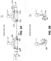
- FIGS 2A and 2B illustrates a side view and a top view of the two clamps 110, respectively, according to some embodiments.
- Each clamp 110 includes a tool mount portion 210 and a grasping portion 220.
- the tool mount portion is configured to engage a lifting mechanism of robotic plate system through clamps arm for moving the pillar plates.
- the grasping portion 220 is configured to freely suspend a pillar plate at an inclination of a non-zero tilt angle relative to a plane normal to the tool mount portion 210.
- the non-zero tilt angle is 3°, 4°, 5°, 6°, 7°, 8°, 9°, 10°, 11°, 12°, 13°, 14°, 15°, 16°, 17°, 18°, 19°, 20°, 21°, 22°, 23°, 24°, 25°, 26°, 27°, 28°, 29°, or 30°. In some embodiments, the non-zero tilt angle is within the range of 5° to 30° (as illustrated in Figure 2A ), less or equal to 30°, or less or equal to 45°.
- the grasping portion 220 includes an inner surface 230 and an outer surface 240.
- the inner surface 230 facing towards and contacting the pillar plate when the clamps of the tool engages with the pillar plate to suspend and move the pillar plate.
- the grasping portion of each clamp includes two pairs of receiving bars 245 and 250.
- the receiving bars 245 of the first pair being separated at a first vertical width 255, while the receiving bars 250 of the second pair are separated at a second vertical width 260.
- each pair of receiving bars forms a separate throat having different width for receiving a protruding edge of the pillar plate.
- the first vertical width exceeds the second vertical width by a pre-defined threshold distance whereby the pillar plate assumes the non-zero tilt angle if the pillar plate is freely suspended by the two clamps of the tool.
- the pre-defined threshold distance equals a factor times the first vertical width with the factor falls within the range of 1 to 2.
- the first vertical width is 2.75 mm.
- the first vertical width is less than 5 mm.
- the first vertical width falls within the range of 1 mm to 5 mm.
- the first vertical width is 1 mm, 1.5 mm, 2 mm, 2.5 mm, 3 mm, 3.5 mm, 4 mm, 4.5 mm, or 5 mm.
- the first vertical width is larger than 5 mm.
- the second vertical width is less than 5.5 mm. In some embodiments, the second vertical width is larger than 5.5 mm.
- the upper receiving bars 265a, 265b of the two pairs are aligned at the non-zero tilted angle and the lower receiving bars 270a, 270b are aligned parallel relative to a plane normal to the tool mount portion.
- the clamps include more than two pairs of receiving bars.
- the receiving bars of the two pairs are connected to form a single pair of receiving bars.
- the receiving bars 245, 250 extend perpendicular from the inner surface 230 of the clamps. In some embodiments, the receiving bars extend a distance that falls within the range of 0.5 mm to 5 mm from the inner surface of the grasping portion. In some embodiments, the receiving bars extend 1 mm from the inner surface. In some embodiments, the receiving bars extend less than 5 mm from the inner surface of the edges of the receiving bar. In some embodiments, the receiving bars extends more than 0.5 mm from the inner surface. In some embodiments, the edges of the receiving bars are graded or rounded to facilitate receiving the protruding edges of the pillar plates.
- the grasping portions of the two clamps are configured to allow a planar surface of the pillar plate to align parallel relative to the plane normal to the tool mount portion if the pillar plate is not freely suspended by the two clamps and is instead buoyant by an assay solution in the one or more wells of a well plate.
- the lower receiving bars 270a, 270b are arranged on the inner surface in a linear alignment perpendicular to the tool mount portion 210.
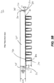
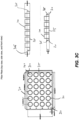
- Figures 3A-3D illustrate pillar plates for assaying microarrays, according to some embodiments.
- Figure 3A shows a top view of an embodiment of a 96-pillar plate 130, including the dimensions of the plate in mm.
- the pillar plate 130 includes two protruding edges 310 on the opposite sides 315 of the pillar plate 130. The protruding edges are configured to engage with the grasping portions of the clamps to suspend the pillar plate.
- the pillar plate 130 further includes one or more alignment marks 320, a plate support 325, and a base region 330 on mounting the pillars 335.
- the alignment marks 320 are centered on each side of the plate support 325 as shown in Figure 3A .
- the alignment marks 320 are placed at opposite corners of the plate support 325 as shown in Figures 3C and 3D .
- the pillars 140 are cylindrical shape as shown in Figures 3C and 3D .
- the pillars have a rectangular shape with the graded edges. Other embodiments include various shapes and sizes of pillars that are known to a person skilled in the art.
- the pillar plate has an area that is larger than 50 square centimeters.
- the pillar plate includes a plurality of pillars that extend approximately perpendicular from the pillar plate.
- one or more microarrays being affixed to at least one pillar so that each microarray is prevented from being displaced from the at least one pillar when the pillar plate is turned upside down.
- the microarrays are functionalized with distinct analyte-detecting regions or biomolecular probes that are synthesized on a substrate of the microarrays by well-known techniques, e.g., the synthesis described in more detail below.
- the microarrays include a wafer.
- the microarrays include a support layer.
- the support layer includes additional features, for example, micropillars.
- one or more microarray is affixed to at least one pillar of the pillar plate so that to prevent displacement of the microarray form the at least one pillar when the pillar plate is turned upside down during assaying biomolecular probes on the microarray.
- microarrays are affixed to a top surface of the pillars with an adhesive.
- the adhesive is an epoxy, a visible light curable epoxy, an ultraviolet light curable glue, or a heat curable glue epoxy.
- the microarrays disclosed herein include chip arrays.
- a chip array is a two-dimensional array of microarrays ("chips") on a plate.
- each microarray only includes a single protein or antibody.
- each microarray includes a plurality of proteins, antibodies, peptides, oligonucleotides, DNA, RNA, peptide nucleic acid (“PNA”), probe molecules and the like.
- the microarray is attached to a cap which attaches to a pillar on a pillar plate.
- microarrays are formed on a silicon wafer, the silicon wafer being the support layer, and then diced into multiple chips of varying dimensions.
- each microarray has a dimension of 1 mm by 1 mm up to 2 cm to 2 cm.
- the microarrays are formed on a wafer and diced into multiple microarrays that fit onto 24-, 96-, 192-, or 384-pillar plates, or any other custom made plates.
- the pillar plate is used for in-vitro diagnostics, such as protein-protein interaction assays or other enzymatic reactions.
- the pillar plates include a plurality of pillars. In some embodiments, number of pillars of the pillar plate is 24, 96, 384, or 1536 pillars.
- Figure 3B also illustrates the pillar plate including two protruding edges on opposite sides of the pillar plate. In some embodiments, the pillars have a top surface 340 and bottom surface 345 with the bottom surface mounted to the base region 330.
- the protruding edges 310 extend 1 mm from plate support 325. In some embodiments, the protruding edges 310 extend less than 1 mm from the plate support. In some embodiments, the protruding edges 310 extend more than 1 mm from the plate support.
- the protruding edges 310 extend a distance from the plate support that falls within a range of 0.5 mm to 5 mm. In some embodiments, the protruding edges extend from the center of the sidewalls 350 of the plate support, as illustrated in Figure 3B . In embodiments, the protruding edges extend from a region of the sidewalls 340 that is off-center, for example, the lower edges 355 or upper edges 360 of the sidewalls 350.
- the pillar plates include a periphery wall 365.
- the protruding edges 310 extending from the periphery wall 365 instead of the plate support 325, as shown in Figure 3D .
- the protruding edges, the alignment marks, the plate support, the base region, the pillars, the periphery wall are integrally molded features of plate pillar.
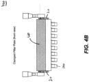
- FIGS 4A and 4B illustrate the side and front view of a tool assembly for assaying microarrays that includes the tool comprising two clamps and the pillar plate, according to some embodiments.
- each of two protruding edges are both separately interlocked with the two pairs of receiving bars of one of the two clamps as the pillar plate is suspended by the two clamps.
- each of two protruding edges are both separately interlocked with the two pairs receiving bars of one of the two clamps as the pillar plate is not freely suspended by the two clamps.
- the suspended pillar plate is shown at a non-zero tilt angle (5°-30°) in Figures 4A and 4B.
- Figure 4B illustrates the front view of the tool assembly showing the bottom surface 410 of the pillar plate (shaded area).
- Figures 4A and 4B further illustrate the off-center position 170, at which the grasping portion of the clamps interlock with the protruding edges 310 of the pillar plate.
- the upper receiving bars of the two pairs of receiving bars of each of the two clamps are configured to individually or in combination exert a downward force on the interlocked protruding edges of the pillar plate if the pillar plate is freely suspended by the two clamps.
- the lower receiving bars of the second pair of receiving bars are configured to exert an upward force on the interlocked protruding edges of the pillar plate if the pillar plate is freely suspended by the two clamps.
- the two clamps included in the tool assembly are configured to allow the pillar plate to align parallel relative to the plane normal to the tool mount portion if one or more pillars of the pillar plate are immersed beyond a threshold depth within an assay solution in one or more wells of a well plate.
- the lower receiving bars of the pairs of receiving bars of the two clamps are configured to individually or in combination exert an upward force on the interlocked protruding edges of the pillar plate if the pillar plate is not freely suspended by the two clamps.
- the upper receiving bars of the second pair of receiving bas of the two clamps are configured to exert a downward force on the interlocked protruding edges of the pillar plate if the pillar plate is not freely suspended by the two clamps
- the number of pillars of the pillar plate is selected from a group consisting of 24, 96, 384, and 1536. In some embodiments of the tool assembly, the pillar plate has an area that is larger than 50 square centimeters.
- the two clamps each include: (1) a tool mount portion that is configured to engage a lifting mechanism of a plate handling robot for moving a pillar plate comprising microarrays; (2) and a grasping portion that is configured to freely suspend a pillar plate at an inclination of a non-zero tilt angle relative to a plane normal to the tool mount portion.
- the non-zero tilt angle is 3°, 4°, 5°, 6°, 7°, 8°, 9°, 10°, 11°, 12°, 13°, 14°, 15°, 16°, 17°, 18°, 19°, 20°, 21°, 22°, 23°, 24°, 25°, 26°, 27°, 28°, 29°, or 30°. In some embodiments, the non-zero tilt angle is within the range of 5° to 30°, less or equal to 30°, or less or equal to 45°.
- the microarrays are functionalized with distinct analyte-detecting regions or biomolecular probes that are synthesized on a substrate of the microarrays by well-known techniques, e.g., the synthesis described in more detail below.
- one or more microarray is affixed to at least one pillar of the pillar plate so that to prevent displacement of the microarray form the at least one pillar when the pillar plate is turned upside down during assaying biomolecular probes on the microarray.
- microarrays are affixed to a top surface of the pillars with an adhesive.
- the adhesive is an epoxy, a visible light curable epoxy, an ultraviolet light curable glue, or a heat curable glue epoxy.
- Embodiments of a microarray comprise a substrate and features attached to the substrate surface at positionally-defined locations.
- a microarray comprises two-dimensional array, wherein the positionally-defined locations occupy a 2-dimensional plane.
- each feature can comprise: a collection of peptide chains of determinable sequence and intended length, wherein within an individual feature, the fraction of peptide chains within said collection having the intended length is characterized by an average coupling efficiency for each coupling step of about 98%.
- the average coupling efficiency for each coupling step is at least 98.5%. In some embodiments, the average coupling efficiency for each coupling step is at least 99%.
- the average coupling efficiency for each coupling step is at least 90, 91, 92, 93, 94, 95, 96, 97, 98, 98.5, 98.6,98.7, 98.8, 98.9, 99.0, 99.1, 99.2, 99.3, 99.4, 99.5, 99.6, 99.7, 99.8, 99.9, or 100%.
- the features attached to the substrate surface are selected from a group consisting of: proteins, DNA binding sequences, antibodies, peptides, oligonucleotides, nucleic acids, peptide nucleic acids, deoxyribonucleic acids, ribonucleic acids, peptide mimetics, nucleotide mimetics, chelates, biomarkers, and the like.
- the substrate surface of the microarray is functionalized with free amine or free carboxylic acids for polypeptide synthesis.
- the free carboxylic acids are activated to bind to amine groups, e.g., during polypeptide synthesis on the surface of the microarray.
- the surface density of features on the microarray is greater than 10/cm 2 , 100/cm 2 , 1,000/cm 2 , 10,000/cm 2 , 100,000/cm 2 , 1,000,000/cm 2 , 10,000,000/cm 2 or 20,000,000/cm 2 .
- the total number of features on the microarray is at least about 100,000, 200,000, 300,000, 400,000, 500,000, 600,000, 700,000, 800,000, 900,000, 1,000,000, 2,000,000, 3,000,000, 4,000,000, 5,000,000, 6,000,000, 7,000,000, 8,000,000, 10,000,000, 12,000,000, 14,000,000, 16,000,000, or 18,000,000.
- the size of the microarray is less than or equal to 0.1, 0.2, 0.3, 0.4, 0.5,0.6, 0.7, 0.8, 0.9, 1, 2, 3, 4, 5, 6, 7, 8, 9, 10, 15, 20, 25, 30, 35, 40, 45, 50, 55, 60, 65, 70, 75, 80, 85, 90, 95, 100, 110, 120, 130, 140, 150, 160, 170, 180, 190, 200, 250, 300, 400, 500, 600, 700, 800, 900, or 1,000 square millimeters.
- a microarray can be a three-dimensional array, e.g., the substrate comprising a porous layer with features attached to the surface of the porous layer.
- the surface of a porous layer includes external surfaces and surfaces defining pore volume within the porous layer.
- a three-dimensional microarray can include features attached to a surface at positionally-defined locations, said features each comprising: a collection of peptide chains of determinable sequence and intended length.
- the fraction of peptide chains within said collection having the intended length is characterized by an average coupling efficiency for each coupling step of greater than 98%.
- the average coupling efficiency for each coupling step is at least 90, 91, 92, 93, 94, 95, 96, 97, 98, 98.5, 98.6,98.7, 98.8, 98.9, 99.0, 99.1, 99.2, 99.3, 99.4, 99.5, 99.6, 99.7, 99.8, 99.9, or 100%.
- each peptide chain is from 5 to 60 amino acids in length. In some embodiments, each peptide chain is at least 5 amino acids in length. In some embodiments, each peptide chain is at least 5, 10, 15, 20, 25, 30, 35, 40, 45, 50, 55, or 60 amino acids in length. In some embodiments, each peptide chain is less than 5, at least 5, 6, 7, 8, 9, 10, 11, 12, 13, 14, 15, 16, 17, 18, 19, 20, 21, 22, 23, 24, 25, 26, 27, 28, 29, 30, 31, 32, 33, 34, 35, 36, 37, 38, 39, 40, 41, 42, 43, 44, 45, 46, 47, 48, 49, 50, 51, 52, 53, 54, 55, 56, 57, 58, 59, 60, or greater than 60 amino acids in length.
- each peptide chain comprises one or more L amino acids. In some embodiments, each peptide chain comprises one or more D amino acids. In some embodiments, each peptide chain comprises one or more naturally occurring amino acids. In some embodiments, each peptide chain comprises one or more synthetic amino acids.
- a microarray can include at least 1,000 different peptide chains attached to the surface. In some embodiments, a microarray can include at least 10,000 different peptide chains attached to the surface. In some embodiments, a microarray can include at least 100, 500, 1000, 2000, 3000, 4000, 5000, 6000, 7000, 8000, 9000, 10,000, or greater than 10,000 different peptide chains attached to the surface (or any integer in between).
- a microarray can include a single protein, peptide chain, or antibody attached to a plurality of different types of linker molecules. In some embodiments a microarray can include at least 2 different types of linker molecules. In some embodiments, a microarray can include at least 2, 3, 4, 5, 6, 7, 8, 9, 10, 15, 20, 25, 30, 40, 50, 75, or greater than 100 different types of linker molecules attached to the substrate.
- each of the positionally-defined locations is at a different, known location that is physically separated from each of the other positionally-defined locations. In some embodiments, each of the positionally-defined locations is a positionallydistinguishable location. In some embodiments, each determinable sequence is a known sequence. In some embodiments, each determinable sequence is a distinct sequence.
- the features are covalently attached to the surface.
- said peptide chains are attached to the surface through a linker molecule or a coupling molecule.
- the features comprise a plurality of distinct, nested, overlapping peptide chains comprising subsequences derived from a source protein having a known sequence.
- each peptide chain in the plurality is substantially the same length.
- each peptide chain in the plurality is the same length.
- each peptide chain in the plurality is at least 5 amino acids in length.
- each peptide chain in the plurality is at least 5, 10, 15, 20, 25, 30, 35, 40, 45, 50, 55, or 60 amino acids in length.
- each peptide chain in the plurality is less than 5, at least 5, 6, 7, 8, 9, 10, 11, 12, 13, 14, 15, 16, 17, 18, 19, 20, 21, 22, 23, 24, 25, 26, 27, 28, 29, 30, 31, 32, 33, 34, 35, 36, 37, 38, 39, 40, 41, 42, 43, 44, 45, 46, 47, 48, 49, 50, 51, 52, 53, 54, 55, 56, 57, 58, 59, 60, or greater than 60 amino acids in length.
- at least one peptide chain in the plurality is at least 5 amino acids in length.
- at least one peptide chain in the plurality is at least 5, 10, 15, 20, 25, 30, 35, 40, 45, 50, 55, or 60 amino acids in length.
- At least one peptide chain in the plurality is less than 5, at least 5, 6, 7, 8, 9, 10, 11, 12, 13, 14, 15, 16, 17, 18, 19, 20, 21, 22, 23, 24, 25, 26, 27, 28, 29, 30, 31, 32, 33, 34, 35, 36, 37, 38, 39, 40, 41, 42, 43, 44, 45, 46, 47, 48, 49, 50, 51, 52, 53, 54, 55, 56, 57, 58, 59, 60, or greater than 60 amino acids in length.
- each polypeptide in a feature is substantially the same length.
- each polypeptide in a feature is the same length.
- the features comprise a plurality of peptide chains each having a random, determinable sequence of amino acids.
- microarrays are methods of using substrates, formulations, and/or microarrays.
- Uses of the microarrays disclosed herein can include research applications, therapeutic purposes, medical diagnostics, and/or stratifying one or more patients.
- Figure 5 illustrate a tool assembly for assaying microarrays at different stages of performing steps in assaying microarrays, according to some embodiments.
- the method of using a tool assembly for assaying microarrays that reduces the likelihood of air bubbles being trapped by the microarrays includes the following steps.
- a tool assembly as described is provided first.
- a well plate that includes a plurality of wells is provided. Each well is capable of receiving one pillar of the pillar plate, when the pillar plate is inclined at the non-zero tilt angle relative to the plane normal to the tool mount portion of the clamps and the microarrays are contacted with an assay solution in one or more wells of the well plate.
- the wells are of cylindrical or rectangular shape. To allow the wells to receive the pillars, the diameter of the wells exceeds the cross-sectional diameter of the pillars as measured perpendicular relative to the tool mount portion of the clamps.
- the pillar plate of the tool assembly is freely suspended inclined at the non-zero tilt angle relative to the plane normal to the tool mount portion of the clamps.
- This step includes interlocking the protruding edges of the pillar plate with the grasping portions of the clamps while the pillar plate is turned upside down and the tool mount portion of the clamps are engaged with a lifting mechanism of a plate handling robot.
- the one or more microarrays affixed to the at least one pillar of the pillar plate are assayed by moving the freely suspended pillar plate towards the well plate and contacting the one or more microarray with an assay solution in the wells.
- the stages shown in Figure 5 include the tool assembly in a first stage of the freely suspended and inverted pillar plate.
- the second stage shows the tool assembly with the one of the pillars of the pillar plate contacting the assay solution in one of the wells.
- the pillar plate is suspended at a non-zero tilt angle.
- the third stage shows the pillars of pillar plate immersed in the assay solution. The solution buoys the pillar plate, counteracting the gravitational forces acting on the pillar plate.
- the pillar plate is aligned parallel relative to the plane normal to the tool mount portion. In this stage, the lower receiving bars of the two pairs of each clamps still provide support for the pillar plate, preventing the pillars from moving even further downwards into the wells.
- microarrays can be used as a research tool or in a research application.
- microarrays can be used for high throughput screening assays.
- enzyme substrates i.e., peptides on a peptide microarray described herein
- enzyme substrates can be tested by subjecting the microarray to an enzyme and identifying the presence or absence of enzyme substrate(s) on the microarray, e.g., by detecting at least one change among the features of the microarray.
- Microarrays can also be used in screening assays for ligand binding, to determine substrate specificity, or for the identification of peptides that inhibit or activate proteins. Labeling techniques, protease assays, as well as binding assays useful for carrying out these methodologies are generally well-known to one of skill in the art.
- a microarray can be used to represent a known protein sequence as a sequence of overlapping peptides.
- the amino acid sequence of a known protein is divided into overlapping sequence segments of any length and of any suitable overlapping frame, and peptides corresponding to the respective sequence segments are in-situ synthesized as disclosed herein.
- the individual peptide segments so synthesized can be arranged starting from the amino terminus of the known protein.
- a microarray is used in a method wherein the antigenic representation of the microarray includes at least one region where the whole antigen sequence of a known protein is spanned via epitope sliding; the immunoactive regions of the antigen are determined by contacting one or more clinical samples on the array or a plurality of different microarrays, and the set of peptide sequences required to represent the known protein antigen are reduced.
- a sample is applied to a microarray having a plurality of random peptides.
- the random peptides can be screened and BLASTed to determine homologous domains with, e.g., a 90% or more identity to a given antigenic sequence.
- the whole antigenic sequence can then be synthesized and used to identify potential markers and/or causes of a disease of interest.
- a microarray is used for high throughput screening of one or more genetic factors.
- Proteins associated with a gene can be a potential antigen and antibodies against these proteins can be used to estimate the relation between gene and a disease.
- a microarray can be used to identify one or more biomarkers.
- Biomarkers can be used for the diagnosis, prognosis, treatment, and management of diseases. Biomarkers may be expressed, or absent, or at a different level in an individual, depending on the disease condition, stage of the disease, and response to disease treatment. Biomarkers can be, e.g., DNA, RNA, proteins (e.g., enzymes such as kinases), sugars, salts, fats, lipids, or ions.
- Microarrays can also be used for therapeutic purposes, e.g., identifying one or more bioactive agents.
- a method for identifying a bioactive agent can comprise applying a plurality of test compounds to a microarray and identifying at least one test compound as a bioactive agent.
- the test compounds can be small molecules, aptamers, oligonucleotides, chemicals, natural extracts, peptides, proteins, fragment of antibodies, antibody like molecules or antibodies.
- the bioactive agent can be a therapeutic agent or modifier of therapeutic targets.
- Therapeutic targets can include phosphatases, proteases, ligases, signal transduction molecules, transcription factors, protein transporters, protein sorters, cell surface receptors, secreted factors, and cytoskeleton proteins.
- a microarray can be used to identify drug candidates for therapeutic use. For example, when one or more epitopes for specific antibodies are determined by an assay (e.g., a binding assay such as an ELISA), the epitopes can be used to develop a drug (e.g., a monoclonal neutralizing antibody) to target antibodies in disease.
- an assay e.g., a binding assay such as an ELISA
- the epitopes can be used to develop a drug (e.g., a monoclonal neutralizing antibody) to target antibodies in disease.
- microarrays for use in medical diagnostics.
- An array can be used to determine a response to administration of drugs or vaccines.
- an individual's response to a vaccine can be determined by detecting the antibody level of the individual by using a microarray with peptides representing epitopes recognized by the antibodies produced by the induced immune response.
- Another diagnostic use is to test an individual for the presence of biomarkers, wherein samples are taken from a subject and the sample is tested for the presence of one or more biomarkers.
- Microarrays can also be used to stratify patient populations based upon the presence or absence of a biomarker that indicates the likelihood a subject will respond to a therapeutic treatment.
- the microarrays can be used to identify known biomarkers to determine the appropriate treatment group. For example, a sample from a subject with a condition can be applied to a microarray. Binding to the microarray may indicate the presence of a biomarker for a condition. Previous studies may indicate that the biomarker is associated with a positive outcome following a treatment, whereas absence of the biomarker is associated with a negative or neutral outcome following a treatment. Because the patient has the biomarker, a health care professional may stratify the patient into a group that receives the treatment.
- a method of detecting the presence or absence of a molecule of interest in a sample can include obtaining a microarray disclosed herein and contacted with a sample suspected of comprising the molecule of interest; and determining whether the molecule of interest is present in the sample by detecting the presence or absence of binding to one or more features of the microarray.
- a molecule of interest e.g., a protein, an antibody, or any other ligand
- a molecule of interest can be detected within a sample that has a volume that is less than or equal to 100, 50, 10, 5, 1.5, or 1 ⁇ L. In some embodiments, the elapsed time from the sample contacting to detection of a molecule of interest is less than 40, 30, 20, 19, 18, 17, 16, 15, 14, 13, 12, 11, 10, 9, 8, 7, 6, 5, 4, 3, 2, or 1 minutes. In some embodiment, a molecule of interest can be detected at a concentration in the contacted sample that falls within the range of about 1 pg/ml to 1,000 ⁇ g/ml.
- the protein of interest may be obtained from a bodily fluid, such as amniotic fluid, aqueous humour, vitreous humour, bile, blood serum, breast milk, cerebrospinal fluid, cerumen, chyle, endolymph, perilymph, feces, female ejaculate, gastric acid, gastric juice, lymph, mucus, peritoneal fluid, pleural fluid, pus, saliva, sebum, semen, sweat, synovial fluid, tears, vaginal secretion, vomit, or urine.
- a bodily fluid such as amniotic fluid, aqueous humour, vitreous humour, bile, blood serum, breast milk, cerebrospinal fluid, cerumen, chyle, endolymph, perilymph, feces, female ejaculate, gastric acid, gastric juice, lymph, mucus, peritoneal fluid, pleural fluid, pus, saliva, sebum, semen, sweat
- a method of identifying a vaccine candidate can include obtaining a microarray disclosed herein contacted with a sample derived from a subject previously administered the vaccine candidate, wherein the sample comprises a plurality of antibodies; and determining the binding specificity of the plurality of antibodies to one or more features of the microarray.
- the features comprise a plurality of distinct, nested, overlapping peptide chains comprising subsequences derived from a source protein having a known sequence.
- the microarrays disclosed herein can be synthesized in situ on a surface, e.g., the substrate disclosed herein.
- the microarrays are made using photolithography.
- the substrate is contacted with a photoactive coupling solution.
- Masks can be used to control radiation or light exposure to specific locations on a surface provided with free linker molecules or free coupling molecules having protecting groups. In the exposed locations, the protecting groups are removed, resulting in one or more newly exposed reactive moieties on the coupling molecule or linker molecule.
- the desired linker or coupling molecule is then coupled to the unprotected attached molecules, e.g., at the carboxylic acid group.
- the process can be repeated to synthesize a large number of features in specific or positionally-defined locations on a surface (see, for example, U.S. Pat. No. 5,143,854 to Pirrung et al. , U.S. Patent Application Publication Nos. 2007/0154946 (filed on Dec. 29, 2005 ), 2007/0122841 (filed on Nov. 30, 2005), 2007/0122842 (filed on Mar. 30, 2006), 2008/0108149 (filed on Oct. 23, 2006), and 2010/0093554 (filed on June 2, 2008 ).
- a method of producing a three-dimensional microarray of features can include obtaining a porous layer attached to a surface; and attaching the features to the porous layer, said features each comprising a collection of peptide chains of determinable sequence and intended length, wherein within an individual feature, the fraction of peptide chains within said collection having the intended length is characterized by an average coupling efficiency for each coupling step of at least about 98%.
- the features are attached to the surface using a photoactive coupling formulation, comprising a photoactive compound, a coupling molecule, a coupling reagent, a polymer, and a solvent.
- the features are attached to the surface using a photoactive coupling formulation disclosed herein.
- the photoactive coupling formulation is stripped away using water.
- a surface comprising attached carboxylic acid groups is provided.
- the surface is contacted with a photoactive coupling solution comprising a photoactive compound, a coupling molecule, a coupling reagent, a polymer, and a solvent.
- the surface is exposed to ultraviolet light in a deep ultra violet scanner tool according to a pattern defined by a photomask, wherein the locations exposed to ultraviolet light undergo photo base generation due to the presence of a photobase generator in the photoactive coupling solution.
- the expose energy can be from 1mJ/cm 2 to 100mJ/cm 2 in order to produce enough photobase.
- the surface is post baked upon exposure in a post exposure bake module.
- Post exposure bake acts as a chemical amplification step.
- the baking step amplifies the initially generated photobase and also enhances the rate of diffusion to the substrate.
- the post bake temperature can vary between 75° Celsius to 115° Celsius, depending on the thickness of the porous surface, for at least 60 seconds and not usually exceeding 120 seconds.
- the free carboxylic acid group is coupled to the deprotected amine group of a free peptide or polypeptide, resulting in coupling of the free peptide or polypeptide to the carboxylic acid group attached to the surface.
- This surface may be a porous surface.
- synthesis of peptides coupled to a carboxylic acid group attached to the surface occurs in an N->C synthesis orientation, with the amine group of free peptides attaching to carboxylic acid groups bound to the surface of the substrate.
- a diamine linker may be attached to a free carboxylic acid group to orient synthesis in a C ⁇ N direction, with the carboxylic acid group of free peptides attaching to amine groups bound to the surface of the substrate.
- the photoactive coupling solution can now be stripped away.
- a method of stripping the photoresist completely with deionized (DI) water This process is accomplished in a developer module.
- the wafer is spun on a vacuum chuck for, e.g., 60 seconds to 90 seconds and deionized water is dispensed through a nozzle for about 30 seconds.
- DI deionized
- the photoactive coupling formulation may be applied to the surface in a coupling spin module.
- a coupling spin module can typically have 20 nozzles or more to feed the photoactive coupling formulation. These nozzles can be made to dispense the photoactive coupling formulation by means of pressurizing the cylinders that hold these solutions or by a pump that dispenses the required amount.
- the pump is employed to dispense 5-8 cc of the photoactive coupling formulation onto the substrate.
- the substrate is spun on a vacuum chuck for 15-30 seconds and the photoactive coupling formulation is dispensed.
- the spin speed can be set to 2000 rpm to 2500 rpm.
- a cap film solution coat is applied on the surface to prevent the nonreacted amino groups on the substrate from reacting with the next coupling molecule.
- the cap film coat solution can be prepared as follows: a solvent, a polymer, and a coupling molecule.
- the solvent that can be used can be an organic solvent like N-methyl pyrrolidone, dimethyl formamide, or combinations thereof.
- the capping molecule is typically acetic anhydride and the polymer can be polyvinyl pyrrolidone, polyvinyl alcohol, polymethyl methacrylate, poly-(methyl-isopropenyl)-ketone, or poly-(2-methyl-pentene-1-sulfone).
- the capping molecule is ethanolamine.
- a capping spin module can include one nozzle that can be made to dispense the cap film coat solution onto the substrate. This solution can be dispensed through pressurizing the cylinder that stores the cap film coat solution or through a pump that precisely dispenses the required amount. In some embodiments, a pump is used to dispense around 5-8 cc of the cap coat solution onto the substrate. The substrate is spun on a vacuum chuck for 15-30 seconds and the coupling formulation is dispensed. The spin speed can be set to 2000 to 2500 rpm.
- a capping bake module is a hot plate set up specifically to receive wafers just after the capping film coat is applied.
- a stripper module can include several nozzles, typically up to 10, set up to dispense organic solvents such as acetone, isopropyl alcohol, N-methyl pyrrolidone, dimethyl formamide, DI water, etc.
- the nozzles can be designated for acetone followed by isopropyl alcohol to be dispensed onto the spinning wafer.
- the spin speed is set to be 2000 to 2500 rpm for around 20 seconds.
- This entire cycle can be repeated as desired with different coupling molecules each time to obtain a desired sequence.
- a microarray comprising a surface of free carboxylic acids is used to synthesize polypeptides in an N ⁇ C orientation.
- the carboxylic acids on the surface of the substrate are activated (e.g., converted to a carbonyl) to allow them to bind to free amine groups on an amino acid.
- activation of carboxylic acids on the group of the surface can be done by addition of a solution comprising a carbodiimide or succinimide to the surface of the microarray.
- carboxylic acids can be activated by addition of a solution comprising 1-ethyl-3-(3-dimethylaminopropyl)-carbodiimide (EDC), N-hydroxysuccinimide (NHS), 1,3-diisopropylcarbodiimide (DIC), hydroxybenzotriazole (HOBt), O-(7-azabenzotriazol-1-yl)-N,N,N',N'-tetramethyluronium hexafluorophosphate (HATU), benzotriazol-1-yl-oxytripyrrolidinophosphonium hexafluorophosphate (PyBOP), or N,N-diisopropylethylamine (DIEA) to the surface of the microarray.
- EDC 1-ethyl-3-(3-dimethylaminopropyl)-carbodiimide
- NHS N-hydroxysuccinimide
- DIC 1,3-diisopropy
- the activation solution is washed away and the surface of the microarray is prepared for addition of an amino acid layer (i.e., one amino acid at each activated carboxylic acid group).
- Carboxylic acid groups remain activated for up to 2, 3, 4, 5, 6, 7, 8, 9, or 10 hours.
- the amino acid comprises an amino acid with protected amine groups.
- the protecting group can be removed from the amine group of selected amino acids at site-specific locations using a reticle. For example, Fmoc-protected amino acids are mixed in a solution comprising a photobase.
- the photobase Upon exposure of the solution on the microarray to a specific frequency of light at site-specific locations, the photobase will release a base which will deprotect the amino acid, resulting in coupling of the amino acid to the activated carboxylic acid group on the surface of the microarray.
- Another method of generating a base is through the use of a photoacid generator.
- the photoacid generator is N-boc-piperidine or 1-boc-4-piperazine.
- peptides synthesized in the N->C terminus direction can be capped with a diamine molecule to enhance binding properties of selected polypeptide sequences to a biological molecule, e.g., an antibody.
- peptides synthesized in the C ⁇ N direction can be capped with a dicarboxylic acid molecule to enhance binding properties of selected sequences to a biological molecule.
- the method described herein ensures complete activation of carboxylic acid on the surface of the microarray. Due to stability of the activated ester for an extended period of time, 2, 3, 4, 5, 6, 7, 8, 9, 10, 11, 12, 13, 14, 15, 16, 17, 18, 19, 20, 21, 22, 23, 24, 25 or more coupling cycles may be completed after a single activation step (e.g., to couple an entire layer of 2-25 or more different amino acids at different locations on the microarray).
- microarrays are described in International Patent Application Nos. PCT/US2013/025190 , PCT/US2013/062773 , PCT/US2013/070207 , PCT/US2014/016737 , PCT/US2015/017173 , and PCT/US2015/049528 .
Landscapes
- Chemical & Material Sciences (AREA)
- Health & Medical Sciences (AREA)
- Analytical Chemistry (AREA)
- General Health & Medical Sciences (AREA)
- Life Sciences & Earth Sciences (AREA)
- Immunology (AREA)
- Physics & Mathematics (AREA)
- Biochemistry (AREA)
- General Physics & Mathematics (AREA)
- Pathology (AREA)
- Chemical Kinetics & Catalysis (AREA)
- Engineering & Computer Science (AREA)
- Organic Chemistry (AREA)
- Clinical Laboratory Science (AREA)
- Hematology (AREA)
- Zoology (AREA)
- Proteomics, Peptides & Aminoacids (AREA)
- Wood Science & Technology (AREA)
- Robotics (AREA)
- Biotechnology (AREA)
- Bioinformatics & Cheminformatics (AREA)
- General Engineering & Computer Science (AREA)
- Genetics & Genomics (AREA)
- Molecular Biology (AREA)
- Microbiology (AREA)
- Biophysics (AREA)
- Apparatus Associated With Microorganisms And Enzymes (AREA)
- Automatic Analysis And Handling Materials Therefor (AREA)
- Sampling And Sample Adjustment (AREA)
Claims (12)
- Werkzeug (100) zum Testen von Mikroarrays, das die Wahrscheinlichkeit reduziert, dass Luftblasen von den Mikroarrays eingeschlossen werden, umfassend:
zwei Klemmen (110), wobei jede der zwei Klemmen (110) umfasst:einen Werkzeugmontageabschnitt (210), wobei der Werkzeugmontageabschnitt (210) dazu konfiguriert ist, in einen Hebemechanismus eines Plattenhandhabungsroboters zum Bewegen einer Säulenplatte (130) einzugreifen, die Mikroarrays umfasst, undeinen Greifabschnitt (220), und dadurch gekennzeichnet, dass der Greifabschnitt (220) dazu konfiguriert ist, die Säulenplatte (130) mit einer Neigung eines Kippwinkels ungleich Null relativ zu einer Ebene senkrecht zu dem Werkzeugmontageabschnitt (210) frei aufzuhängen. - Werkzeug nach Anspruch 1, wobei der Greifabschnitt (220) jeder Klemme (110) zwei Paare von Aufnahmestäben (245, 250) umfasst, wobei die Aufnahmestäbe (245) des ersten Paares in einer ersten vertikalen Breite (255) voneinander getrennt sind, die Aufnahmestäbe (250) des zweiten Paares in einer zweiten vertikalen Breite (260) voneinander getrennt sind und die erste vertikale Breite (255) die zweite vertikale Breite (260) um einen vordefinierten Schwellenabstand übersteigt, wodurch die Säulenplatte (130) den Kippwinkel ungleich Null einnimmt, wenn die Säulenplatte (130) durch die zwei Klemmen (110) frei aufgehängt ist, optional wobei die oberen Aufnahmestäbe (265a, 265b) der zwei Paare von Aufnahmestäben in dem Kippwinkel ungleich Null ausgerichtet sind und die unteren Aufnahmestäbe (270a, 270b) parallel relativ zu einer Ebene senkrecht zu dem Werkzeugmontageabschnitt (210) ausgerichtet sind.
- Werkzeug nach Anspruch 1, wobei die Greifabschnitte (220) der zwei Klemmen (110) dazu konfiguriert sind, einer ebenen Oberfläche der Säulenplatte (130) zu ermöglichen, sich parallel zu der Ebene senkrecht zu dem Werkzeugmontageabschnitt (210) auszurichten, wenn die Säulenplatte (130) nicht frei durch die zwei Klemmen (110) aufgehängt ist und stattdessen durch eine Assaylösung in dem einen oder den mehreren Wells einer Wellplatte (150) schwimmend gehalten wird.
- Werkzeug nach Anspruch 1, wobei der Kippwinkel ungleich Null ist:a) innerhalb des Bereichs von 5° bis 30°; oderb) 3°, 4°, 5°, 6°, 7°, 8°, 9°, 10°, 11°, 12°, 13°, 14°, 15°, 16°, 17°, 18°, 19°, 20°, 21°, 22°, 23°, 24°, 25°, 26°, 27°, 28°, 29° oder 30°; oderc) kleiner oder gleich 30°; oderd) kleiner oder gleich 45°.
- Werkzeugbaugruppe zum Testen von Mikroarrays, die die Wahrscheinlichkeit reduziert, dass Luftblasen von den Mikroarrays eingeschlossen werden, umfassend:ein Werkzeug (100) nach einem der Ansprüche 1 bis 3; undeine Säulenplatte (130), umfassend eine Mehrzahl von Säulen (140), die sich ungefähr senkrecht von der Säulenplatte (130) erstrecken, wobei ein oder mehrere Microarrays an wenigstens einer Säule (140) befestigt sind, sodass jedes Microarray daran gehindert wird, von der wenigstens einen Säule (140) verschoben zu werden, wenn die Säulenplatte (130) umgedreht wird, und die Säulenplatte (130) ferner zwei vorstehende Kanten (310) auf gegenüberliegenden Seiten der Säulenplatte (130) umfasst,wobei die vorstehenden Kanten (310) dazu konfiguriert sind, in die Greifabschnitte (220) der Klemmen einzugreifen, um die Säulenplatte (130) aufzuhängen.
- Werkzeugbaugruppe nach Anspruch 5, wobei jede der zwei vorstehenden Kanten (310) getrennt mit den zwei Paaren (245, 250) von Aufnahmestangen einer der zwei Klemmen (110) verriegelt ist, wenn die Säulenplatte (130) durch die zwei Klemmen (110) aufgehängt ist.
- Werkzeugbaugruppe nach Anspruch 6, wobei:a) die oberen Aufnahmestäbe (265a, 265b) der zwei Paare von Aufnahmestäben jeder der zwei Klemmen (110) dazu konfiguriert sind, einzeln oder in Kombination eine nach unten gerichtete Kraft auf die verriegelten vorstehenden Kanten (310) der Säulenplatte (130) auszuüben, wenn die Säulenplatte (130) von den zwei Klemmen (110) frei aufgehängt ist; oderb) die unteren Aufnahmestäbe (270a, 270b) des zweiten Paares von Aufnahmestäben dazu konfiguriert sind, eine nach oben gerichtete Kraft auf die verriegelten vorstehenden Kanten (310) der Säulenplatte (130) auszuüben, wenn die Säulenplatte (130) durch die zwei Klemmen (110) frei aufgehängt ist; oderc) die unteren Aufnahmestäbe (270a, 270b) der Paare von Aufnahmestäben (110) der zwei Klemmen dazu konfiguriert sind, einzeln oder in Kombination eine nach oben gerichtete Kraft auf die verriegelten vorstehenden Kanten (310) der Säulenplatte (130) auszuüben, wenn die Säulenplatte (130) nicht frei an den zwei Klemmen (110) aufgehängt ist; oderd) die oberen Aufnahmestäbe (265a, 265b) des zweiten Paares von Aufnahmestäben der zwei Klemmen (110) dazu konfiguriert sind, eine nach unten gerichtete Kraft auf die verriegelten vorstehenden Kanten (310) der Säulenplatte (130) auszuüben, wenn die Säulenplatte (130) nicht frei durch die zwei Klemmen (110) aufgehängt ist.
- Werkzeugbaugruppe nach Anspruch 5, wobei jede der zwei vorstehenden Kanten (310) jeweils separat mit den zwei Paaren von Aufnahmestangen (245, 250) einer der zwei Klemmen (110) verriegelt sind, wenn die Säulenplatte (130) nicht frei durch die zwei Klemmen (110) aufgehängt ist, oder
wobei die zwei Klemmen (110) dazu konfiguriert sind, zu ermöglichen, dass die Säulenplatte (130) parallel relativ zu der Ebene senkrecht zu dem Werkzeugmontageabschnitt ausgerichtet wird, wenn eine oder mehrere Säulen (140) der Säulenplatte (130) über eine Schwellentiefe hinaus in eine Testlösung in einem oder mehreren Wells einer Wellplatte (150) eingetaucht sind. - Werkzeugbaugruppe nach Anspruch 5, wobei die Anzahl der Säulen (140) der Säulenplatte (130) aus einer Gruppe ausgewählt ist, die aus 24, 96, 384 und 1536 besteht, oder
wobei die Säulenplatte (130) eine Fläche aufweist, die größer als 50 Quadratzentimeter ist. - Werkzeugbaugruppe nach Anspruch 5, wobei der Neigungswinkel ungleich Null ist:a) innerhalb des Bereichs von 5° bis 30°; oderb) 3°, 4°, 5°, 6°, 7°, 8°, 9°, 10°, 11°, 12°, 13°, 14°, 15°, 16°, 17°, 18°, 19°, 20°, 21°, 22°, 23°, 24°, 25°, 26°, 27°, 28°, 29° oder 30°; oderc) kleiner oder gleich 30°; oderd) kleiner oder gleich 45°.
- Werkzeugbaugruppe nach Anspruch 5, wobei die Mikroarrays an einer oberen Oberfläche der Säulen (130) mit einem Klebstoff befestigt sind, wobei der Klebstoff optional aus der Gruppe ausgewählt ist, die aus einem Epoxidharz, einem mit sichtbarem Licht härtbaren Epoxidharz, einem mit ultraviolettem Licht härtbaren Klebstoff und einem hitzehärtbaren Klebstoffepoxidharz besteht.
- Verfahren zum Verwenden einer Werkzeugbaugruppe zum Testen von Mikroarrays, das die Wahrscheinlichkeit reduziert, dass Luftblasen von den Mikroarrays eingeschlossen werden, umfassend:Bereitstellen einer Werkzeugbaugruppe nach einem der Ansprüche 5 bis 11;Bereitstellen einer Wellsplatte (150), umfassend eine Mehrzahl von Wells, wobei jedes Wells in der Lage ist, eine Säule (140) der Säulenplatte (130) aufzunehmen, wenn die Säulenplatte (130) in einem Kippwinkel ungleich Null relativ zu der Ebene senkrecht zu dem Werkzeugmontageabschnitt (210) der Klemmen (110) geneigt ist und die Microarrays mit einer Assaylösung in einem oder mehreren Wells der Wellsplatte (150) in Kontakt gebracht werden;freies Aufhängen der Säulenplatte (130) der Werkzeugbaugruppe, die mit einem Kippwinkel ungleich Null relativ zu der Ebene senkrecht zu dem Werkzeugmontageabschnitt (210) der Klemmen (110) geneigt ist, wobei das freie Aufhängen das Verriegeln der vorstehenden Kanten (310) der Säulenplatte (130) mit den Greifabschnitten (220) der Klemmen (110) umfasst, während die Säulenplatte (130) herumgedreht ist und der Werkzeugmontageabschnitt (210) der Klemmen (110) in einen Hebemechanismus eines Plattenhandhabungsroboters eingreift; undTesten des einen oder der mehreren Mikroarrays, die an der wenigstens einen Säule (140) der Säulenplatte (130) befestigt sind, durch Bewegen der frei aufgehängten Säulenplatte (120) in Richtung der Wellsplatte (150) und Inkontaktbringen des einen oder der mehreren Mikroarrays mit einer Assaylösung in den Wells.
Applications Claiming Priority (2)
| Application Number | Priority Date | Filing Date | Title |
|---|---|---|---|
| US201562248287P | 2015-10-29 | 2015-10-29 | |
| PCT/US2016/058589 WO2017074900A1 (en) | 2015-10-29 | 2016-10-25 | Methods, tools, and tool assemblies for biomolecular analysis using microarrays |
Publications (3)
| Publication Number | Publication Date |
|---|---|
| EP3368909A1 EP3368909A1 (de) | 2018-09-05 |
| EP3368909A4 EP3368909A4 (de) | 2019-07-03 |
| EP3368909B1 true EP3368909B1 (de) | 2023-08-09 |
Family
ID=58631097
Family Applications (1)
| Application Number | Title | Priority Date | Filing Date |
|---|---|---|---|
| EP16860594.7A Active EP3368909B1 (de) | 2015-10-29 | 2016-10-25 | Verfahren, werkzeuge und werkzeuganordnungen für biomolekulare analyse unter verwendung von mikroarrays |
Country Status (7)
| Country | Link |
|---|---|
| US (2) | US11033904B2 (de) |
| EP (1) | EP3368909B1 (de) |
| JP (2) | JP6849675B2 (de) |
| AU (3) | AU2016346170A1 (de) |
| CA (1) | CA3000509C (de) |
| NZ (1) | NZ742318A (de) |
| WO (1) | WO2017074900A1 (de) |
Families Citing this family (3)
| Publication number | Priority date | Publication date | Assignee | Title |
|---|---|---|---|---|
| TWI683900B (zh) * | 2017-05-31 | 2020-02-01 | 台灣生捷科技股份有限公司 | 微陣列載具總成 |
| RU2685655C1 (ru) * | 2018-03-17 | 2019-04-22 | Арсений Андреевич Рабинерсон | Заключающая среда для светового микроскопирования биологических и гистологических микропрепаратов |
| CN113763832B (zh) * | 2021-09-17 | 2024-01-30 | 利亚德光电股份有限公司 | Led显示模组的制备方法 |
Citations (3)
| Publication number | Priority date | Publication date | Assignee | Title |
|---|---|---|---|---|
| EP0154687A2 (de) * | 1982-03-03 | 1985-09-18 | Becton Dickinson and Company | Trageplatte und Anordnung für immunologische Untersuchungen |
| DE4120139C2 (de) * | 1991-06-19 | 1993-09-23 | Bundesrepublik Deutschland, Vertreten Durch Das Bundesministerium Der Verteidigung, Dieses Vertreten Durch Den Praesidenten Des Bundesamtes Fuer Wehrtechnik Und Beschaffung, 56068 Koblenz, De | |
| JP2015158380A (ja) * | 2014-02-21 | 2015-09-03 | 株式会社ニコン | 検出装置、検出方法、バイオアッセイ装置、スクリーニング装置及びスクリーニング方法 |
Family Cites Families (25)
| Publication number | Priority date | Publication date | Assignee | Title |
|---|---|---|---|---|
| US5244788A (en) | 1992-07-01 | 1993-09-14 | Hubscher Thomas T | Method and apparatus for performing determinations of immune rectants in biological fluids |
| JP3813648B2 (ja) * | 1995-09-12 | 2006-08-23 | 高電工業株式会社 | 粒子反応パターン判定装置 |
| JPH09101302A (ja) * | 1995-10-06 | 1997-04-15 | Toppan Printing Co Ltd | マイクロプレート |
| JP3584732B2 (ja) | 1998-05-08 | 2004-11-04 | 松下電器産業株式会社 | 分注装置および分注方法ならびに分注チップの装着方法 |
| US7105129B2 (en) | 2002-05-15 | 2006-09-12 | Genetix Limited | Liquid handling robot for well plates |
| US8652774B2 (en) * | 2003-04-16 | 2014-02-18 | Affymetrix, Inc. | Automated method of manufacturing polyer arrays |
| US20050158212A1 (en) * | 2004-01-15 | 2005-07-21 | Michael Yavilevich | Automated laboratory system and analytical module |
| JP2006126204A (ja) * | 2004-10-29 | 2006-05-18 | Affymetrix Inc | ポリマーアレイを製造するための自動化方法 |
| US7622079B2 (en) * | 2005-03-22 | 2009-11-24 | Applied Biosystems, Llc | Dual nest microplate spotter |
| JP4548356B2 (ja) | 2006-02-13 | 2010-09-22 | セイコーインスツル株式会社 | 自動薄切片標本作製装置及び自動薄切片標本作製方法 |
| US8445201B2 (en) * | 2009-07-31 | 2013-05-21 | Affymetrix, Inc. | Hybridization device, methods, and system using mixing beads |
| KR20120132999A (ko) * | 2011-05-30 | 2012-12-10 | 삼성전기주식회사 | 세포칩 및 그 제조방법 |
| EP2812344A4 (de) | 2012-02-07 | 2015-10-28 | Vibrant Holdings Llc | Substrate, peptidarrays und verfahren |
| US20140052989A1 (en) * | 2012-08-15 | 2014-02-20 | Ultra Electronics, ProLogic | Secure data exchange using messaging service |
| CA3088591C (en) * | 2012-09-28 | 2023-01-03 | Vibrant Holdings, Llc | Inverted pillar plates for assaying microarrays and methods of using same. |
| US10006909B2 (en) | 2012-09-28 | 2018-06-26 | Vibrant Holdings, Llc | Methods, systems, and arrays for biomolecular analysis |
| US10286376B2 (en) | 2012-11-14 | 2019-05-14 | Vibrant Holdings, Llc | Substrates, systems, and methods for array synthesis and biomolecular analysis |
| WO2014127328A2 (en) | 2013-02-15 | 2014-08-21 | Vibrant Holdings, Llc. | Methods and compositions for amplified electrochemiluminescence detection |
| EP3028764A4 (de) | 2013-08-02 | 2017-06-07 | Nikon Corporation | Platte, herstellungsverfahren für platte, biochipbeobachtungsverfahren und screening-verfahren |
| EP3040723A4 (de) * | 2013-08-30 | 2017-07-12 | Nikon Corporation | Biochipträgerelement, verfahren zur herstellung des biochipträgerelements, biochipverpackung, screening-vorrichtung und screening-verfahren |
| WO2015127409A1 (en) | 2014-02-21 | 2015-08-27 | Vibrant Holdings, Llc | Selective photo activation of amino acids for single step peptide coupling |
| WO2016040703A1 (en) | 2014-09-10 | 2016-03-17 | Vibrant Holdings, Llc | Peptide microarrays and novel biomarkers for celiac disease |
| US20180106795A1 (en) | 2015-03-12 | 2018-04-19 | Vibrant Holdings, Llc | Polypeptide arrays and methods of attaching polypeptides to an array |
| AU2016382985A1 (en) | 2015-12-28 | 2018-07-19 | Vibrant Holdings, Llc | Substrates, systems, and methods for nucleic acid array synthesis |
| EP3613736A1 (de) * | 2018-08-22 | 2020-02-26 | Basf Se | Substituierte glutarimidderivate |
-
2016
- 2016-10-25 EP EP16860594.7A patent/EP3368909B1/de active Active
- 2016-10-25 AU AU2016346170A patent/AU2016346170A1/en not_active Abandoned
- 2016-10-25 JP JP2018522145A patent/JP6849675B2/ja active Active
- 2016-10-25 WO PCT/US2016/058589 patent/WO2017074900A1/en active Application Filing
- 2016-10-25 US US15/771,381 patent/US11033904B2/en active Active
- 2016-10-25 CA CA3000509A patent/CA3000509C/en active Active
- 2016-10-25 NZ NZ74231816A patent/NZ742318A/en unknown
-
2019
- 2019-12-20 AU AU2019284016A patent/AU2019284016B2/en active Active
-
2021
- 2021-03-04 JP JP2021034014A patent/JP2021099362A/ja active Pending
- 2021-05-10 US US17/316,111 patent/US20210339247A1/en not_active Abandoned
- 2021-08-02 AU AU2021211980A patent/AU2021211980B2/en active Active
Patent Citations (3)
| Publication number | Priority date | Publication date | Assignee | Title |
|---|---|---|---|---|
| EP0154687A2 (de) * | 1982-03-03 | 1985-09-18 | Becton Dickinson and Company | Trageplatte und Anordnung für immunologische Untersuchungen |
| DE4120139C2 (de) * | 1991-06-19 | 1993-09-23 | Bundesrepublik Deutschland, Vertreten Durch Das Bundesministerium Der Verteidigung, Dieses Vertreten Durch Den Praesidenten Des Bundesamtes Fuer Wehrtechnik Und Beschaffung, 56068 Koblenz, De | |
| JP2015158380A (ja) * | 2014-02-21 | 2015-09-03 | 株式会社ニコン | 検出装置、検出方法、バイオアッセイ装置、スクリーニング装置及びスクリーニング方法 |
Also Published As
| Publication number | Publication date |
|---|---|
| CA3000509A1 (en) | 2017-05-04 |
| JP6849675B2 (ja) | 2021-03-24 |
| WO2017074900A1 (en) | 2017-05-04 |
| US20190030528A1 (en) | 2019-01-31 |
| JP2018536158A (ja) | 2018-12-06 |
| AU2019284016A1 (en) | 2020-01-23 |
| EP3368909A1 (de) | 2018-09-05 |
| AU2016346170A1 (en) | 2018-06-14 |
| AU2019284016B2 (en) | 2021-08-12 |
| EP3368909A4 (de) | 2019-07-03 |
| JP2021099362A (ja) | 2021-07-01 |
| US11033904B2 (en) | 2021-06-15 |
| NZ742318A (en) | 2019-10-25 |
| US20210339247A1 (en) | 2021-11-04 |
| AU2021211980A1 (en) | 2021-08-26 |
| AU2021211980B2 (en) | 2023-09-07 |
| CA3000509C (en) | 2021-07-27 |
Similar Documents
| Publication | Publication Date | Title |
|---|---|---|
| JP7160879B2 (ja) | 生体分子解析のための方法、システム、およびアレイ | |
| US11815512B2 (en) | Methods, systems, and arrays for biomolecular analysis | |
| US20210339247A1 (en) | Methods, tools, and tool assemblies for biomolecular analysis using microarrays | |
| US20210096134A1 (en) | Methods and Compositions for Amplified Electrochemiluminescence Detection Assays |
Legal Events
| Date | Code | Title | Description |
|---|---|---|---|
| STAA | Information on the status of an ep patent application or granted ep patent |
Free format text: STATUS: THE INTERNATIONAL PUBLICATION HAS BEEN MADE |
|
| PUAI | Public reference made under article 153(3) epc to a published international application that has entered the european phase |
Free format text: ORIGINAL CODE: 0009012 |
|
| STAA | Information on the status of an ep patent application or granted ep patent |
Free format text: STATUS: REQUEST FOR EXAMINATION WAS MADE |
|
| 17P | Request for examination filed |
Effective date: 20180327 |
|
| AK | Designated contracting states |
Kind code of ref document: A1 Designated state(s): AL AT BE BG CH CY CZ DE DK EE ES FI FR GB GR HR HU IE IS IT LI LT LU LV MC MK MT NL NO PL PT RO RS SE SI SK SM TR |
|
| AX | Request for extension of the european patent |
Extension state: BA ME |
|
| DAV | Request for validation of the european patent (deleted) | ||
| DAX | Request for extension of the european patent (deleted) | ||
| A4 | Supplementary search report drawn up and despatched |
Effective date: 20190605 |
|
| RIC1 | Information provided on ipc code assigned before grant |
Ipc: B01J 19/00 20060101ALI20190529BHEP Ipc: G01N 33/543 20060101ALN20190529BHEP Ipc: G01N 35/10 20060101ALI20190529BHEP Ipc: G01N 1/28 20060101ALI20190529BHEP Ipc: G01N 35/00 20060101ALN20190529BHEP Ipc: G01N 35/02 20060101ALI20190529BHEP Ipc: B01L 3/00 20060101ALN20190529BHEP Ipc: G01N 35/04 20060101AFI20190529BHEP |
|
| STAA | Information on the status of an ep patent application or granted ep patent |
Free format text: STATUS: EXAMINATION IS IN PROGRESS |
|
| 17Q | First examination report despatched |
Effective date: 20210709 |
|
| STAA | Information on the status of an ep patent application or granted ep patent |
Free format text: STATUS: EXAMINATION IS IN PROGRESS |
|
| GRAP | Despatch of communication of intention to grant a patent |
Free format text: ORIGINAL CODE: EPIDOSNIGR1 |
|
| STAA | Information on the status of an ep patent application or granted ep patent |
Free format text: STATUS: GRANT OF PATENT IS INTENDED |
|
| RIC1 | Information provided on ipc code assigned before grant |
Ipc: B01L 3/00 20060101ALN20230131BHEP Ipc: G01N 33/543 20060101ALN20230131BHEP Ipc: G01N 35/00 20060101ALN20230131BHEP Ipc: G01N 35/02 20060101ALI20230131BHEP Ipc: B01J 19/00 20060101ALI20230131BHEP Ipc: G01N 35/10 20060101ALI20230131BHEP Ipc: G01N 1/28 20060101ALI20230131BHEP Ipc: G01N 35/04 20060101AFI20230131BHEP |
|
| INTG | Intention to grant announced |
Effective date: 20230222 |
|
| RAP3 | Party data changed (applicant data changed or rights of an application transferred) |
Owner name: VIBRANT HOLDINGS, LLC |
|
| P01 | Opt-out of the competence of the unified patent court (upc) registered |
Effective date: 20230516 |
|
| GRAS | Grant fee paid |
Free format text: ORIGINAL CODE: EPIDOSNIGR3 |
|
| GRAA | (expected) grant |
Free format text: ORIGINAL CODE: 0009210 |
|
| STAA | Information on the status of an ep patent application or granted ep patent |
Free format text: STATUS: THE PATENT HAS BEEN GRANTED |
|
| AK | Designated contracting states |
Kind code of ref document: B1 Designated state(s): AL AT BE BG CH CY CZ DE DK EE ES FI FR GB GR HR HU IE IS IT LI LT LU LV MC MK MT NL NO PL PT RO RS SE SI SK SM TR |
|
| REG | Reference to a national code |
Ref country code: GB Ref legal event code: FG4D |
|
| REG | Reference to a national code |
Ref country code: CH Ref legal event code: EP |
|
| REG | Reference to a national code |
Ref country code: IE Ref legal event code: FG4D |
|
| REG | Reference to a national code |
Ref country code: DE Ref legal event code: R096 Ref document number: 602016081834 Country of ref document: DE |
|
| REG | Reference to a national code |
Ref country code: LT Ref legal event code: MG9D |
|
| REG | Reference to a national code |
Ref country code: NL Ref legal event code: MP Effective date: 20230809 |
|
| REG | Reference to a national code |
Ref country code: AT Ref legal event code: MK05 Ref document number: 1598122 Country of ref document: AT Kind code of ref document: T Effective date: 20230809 |
|
| PG25 | Lapsed in a contracting state [announced via postgrant information from national office to epo] |
Ref country code: GR Free format text: LAPSE BECAUSE OF FAILURE TO SUBMIT A TRANSLATION OF THE DESCRIPTION OR TO PAY THE FEE WITHIN THE PRESCRIBED TIME-LIMIT Effective date: 20231110 |
|
| PGFP | Annual fee paid to national office [announced via postgrant information from national office to epo] |
Ref country code: GB Payment date: 20231027 Year of fee payment: 8 |
|
| PG25 | Lapsed in a contracting state [announced via postgrant information from national office to epo] |
Ref country code: IS Free format text: LAPSE BECAUSE OF FAILURE TO SUBMIT A TRANSLATION OF THE DESCRIPTION OR TO PAY THE FEE WITHIN THE PRESCRIBED TIME-LIMIT Effective date: 20231209 |
|
| PG25 | Lapsed in a contracting state [announced via postgrant information from national office to epo] |
Ref country code: SE Free format text: LAPSE BECAUSE OF FAILURE TO SUBMIT A TRANSLATION OF THE DESCRIPTION OR TO PAY THE FEE WITHIN THE PRESCRIBED TIME-LIMIT Effective date: 20230809 Ref country code: RS Free format text: LAPSE BECAUSE OF FAILURE TO SUBMIT A TRANSLATION OF THE DESCRIPTION OR TO PAY THE FEE WITHIN THE PRESCRIBED TIME-LIMIT Effective date: 20230809 Ref country code: PT Free format text: LAPSE BECAUSE OF FAILURE TO SUBMIT A TRANSLATION OF THE DESCRIPTION OR TO PAY THE FEE WITHIN THE PRESCRIBED TIME-LIMIT Effective date: 20231211 Ref country code: NO Free format text: LAPSE BECAUSE OF FAILURE TO SUBMIT A TRANSLATION OF THE DESCRIPTION OR TO PAY THE FEE WITHIN THE PRESCRIBED TIME-LIMIT Effective date: 20231109 Ref country code: NL Free format text: LAPSE BECAUSE OF FAILURE TO SUBMIT A TRANSLATION OF THE DESCRIPTION OR TO PAY THE FEE WITHIN THE PRESCRIBED TIME-LIMIT Effective date: 20230809 Ref country code: LV Free format text: LAPSE BECAUSE OF FAILURE TO SUBMIT A TRANSLATION OF THE DESCRIPTION OR TO PAY THE FEE WITHIN THE PRESCRIBED TIME-LIMIT Effective date: 20230809 Ref country code: LT Free format text: LAPSE BECAUSE OF FAILURE TO SUBMIT A TRANSLATION OF THE DESCRIPTION OR TO PAY THE FEE WITHIN THE PRESCRIBED TIME-LIMIT Effective date: 20230809 Ref country code: IS Free format text: LAPSE BECAUSE OF FAILURE TO SUBMIT A TRANSLATION OF THE DESCRIPTION OR TO PAY THE FEE WITHIN THE PRESCRIBED TIME-LIMIT Effective date: 20231209 Ref country code: HR Free format text: LAPSE BECAUSE OF FAILURE TO SUBMIT A TRANSLATION OF THE DESCRIPTION OR TO PAY THE FEE WITHIN THE PRESCRIBED TIME-LIMIT Effective date: 20230809 Ref country code: GR Free format text: LAPSE BECAUSE OF FAILURE TO SUBMIT A TRANSLATION OF THE DESCRIPTION OR TO PAY THE FEE WITHIN THE PRESCRIBED TIME-LIMIT Effective date: 20231110 Ref country code: FI Free format text: LAPSE BECAUSE OF FAILURE TO SUBMIT A TRANSLATION OF THE DESCRIPTION OR TO PAY THE FEE WITHIN THE PRESCRIBED TIME-LIMIT Effective date: 20230809 Ref country code: AT Free format text: LAPSE BECAUSE OF FAILURE TO SUBMIT A TRANSLATION OF THE DESCRIPTION OR TO PAY THE FEE WITHIN THE PRESCRIBED TIME-LIMIT Effective date: 20230809 |
|
| PGFP | Annual fee paid to national office [announced via postgrant information from national office to epo] |
Ref country code: FR Payment date: 20231027 Year of fee payment: 8 Ref country code: DE Payment date: 20231027 Year of fee payment: 8 Ref country code: CH Payment date: 20231113 Year of fee payment: 8 |
|
| PG25 | Lapsed in a contracting state [announced via postgrant information from national office to epo] |
Ref country code: PL Free format text: LAPSE BECAUSE OF FAILURE TO SUBMIT A TRANSLATION OF THE DESCRIPTION OR TO PAY THE FEE WITHIN THE PRESCRIBED TIME-LIMIT Effective date: 20230809 |
|
| PG25 | Lapsed in a contracting state [announced via postgrant information from national office to epo] |
Ref country code: ES Free format text: LAPSE BECAUSE OF FAILURE TO SUBMIT A TRANSLATION OF THE DESCRIPTION OR TO PAY THE FEE WITHIN THE PRESCRIBED TIME-LIMIT Effective date: 20230809 |
|
| PG25 | Lapsed in a contracting state [announced via postgrant information from national office to epo] |
Ref country code: SM Free format text: LAPSE BECAUSE OF FAILURE TO SUBMIT A TRANSLATION OF THE DESCRIPTION OR TO PAY THE FEE WITHIN THE PRESCRIBED TIME-LIMIT Effective date: 20230809 Ref country code: RO Free format text: LAPSE BECAUSE OF FAILURE TO SUBMIT A TRANSLATION OF THE DESCRIPTION OR TO PAY THE FEE WITHIN THE PRESCRIBED TIME-LIMIT Effective date: 20230809 Ref country code: ES Free format text: LAPSE BECAUSE OF FAILURE TO SUBMIT A TRANSLATION OF THE DESCRIPTION OR TO PAY THE FEE WITHIN THE PRESCRIBED TIME-LIMIT Effective date: 20230809 Ref country code: EE Free format text: LAPSE BECAUSE OF FAILURE TO SUBMIT A TRANSLATION OF THE DESCRIPTION OR TO PAY THE FEE WITHIN THE PRESCRIBED TIME-LIMIT Effective date: 20230809 Ref country code: DK Free format text: LAPSE BECAUSE OF FAILURE TO SUBMIT A TRANSLATION OF THE DESCRIPTION OR TO PAY THE FEE WITHIN THE PRESCRIBED TIME-LIMIT Effective date: 20230809 Ref country code: CZ Free format text: LAPSE BECAUSE OF FAILURE TO SUBMIT A TRANSLATION OF THE DESCRIPTION OR TO PAY THE FEE WITHIN THE PRESCRIBED TIME-LIMIT Effective date: 20230809 Ref country code: SK Free format text: LAPSE BECAUSE OF FAILURE TO SUBMIT A TRANSLATION OF THE DESCRIPTION OR TO PAY THE FEE WITHIN THE PRESCRIBED TIME-LIMIT Effective date: 20230809 |
|
| REG | Reference to a national code |
Ref country code: DE Ref legal event code: R097 Ref document number: 602016081834 Country of ref document: DE |
|
| PG25 | Lapsed in a contracting state [announced via postgrant information from national office to epo] |
Ref country code: IT Free format text: LAPSE BECAUSE OF FAILURE TO SUBMIT A TRANSLATION OF THE DESCRIPTION OR TO PAY THE FEE WITHIN THE PRESCRIBED TIME-LIMIT Effective date: 20230809 Ref country code: MC Free format text: LAPSE BECAUSE OF FAILURE TO SUBMIT A TRANSLATION OF THE DESCRIPTION OR TO PAY THE FEE WITHIN THE PRESCRIBED TIME-LIMIT Effective date: 20230809 |
|
| PLBE | No opposition filed within time limit |
Free format text: ORIGINAL CODE: 0009261 |
|
| STAA | Information on the status of an ep patent application or granted ep patent |
Free format text: STATUS: NO OPPOSITION FILED WITHIN TIME LIMIT |
|
| REG | Reference to a national code |
Ref country code: BE Ref legal event code: MM Effective date: 20231031 |
|
| PG25 | Lapsed in a contracting state [announced via postgrant information from national office to epo] |
Ref country code: LU Free format text: LAPSE BECAUSE OF NON-PAYMENT OF DUE FEES Effective date: 20231025 |
|
| PG25 | Lapsed in a contracting state [announced via postgrant information from national office to epo] |
Ref country code: LU Free format text: LAPSE BECAUSE OF NON-PAYMENT OF DUE FEES Effective date: 20231025 |
|
| 26N | No opposition filed |
Effective date: 20240513 |
|
| PG25 | Lapsed in a contracting state [announced via postgrant information from national office to epo] |
Ref country code: SI Free format text: LAPSE BECAUSE OF FAILURE TO SUBMIT A TRANSLATION OF THE DESCRIPTION OR TO PAY THE FEE WITHIN THE PRESCRIBED TIME-LIMIT Effective date: 20230809 |
|
| PG25 | Lapsed in a contracting state [announced via postgrant information from national office to epo] |
Ref country code: BE Free format text: LAPSE BECAUSE OF NON-PAYMENT OF DUE FEES Effective date: 20231031 |