EP3368795B2 - Getriebe, aufweisend ein zumindest ein erstes und ein zweites gehäuseteil aufweisendes gehäuse - Google Patents
Getriebe, aufweisend ein zumindest ein erstes und ein zweites gehäuseteil aufweisendes gehäuse Download PDFInfo
- Publication number
- EP3368795B2 EP3368795B2 EP16784798.7A EP16784798A EP3368795B2 EP 3368795 B2 EP3368795 B2 EP 3368795B2 EP 16784798 A EP16784798 A EP 16784798A EP 3368795 B2 EP3368795 B2 EP 3368795B2
- Authority
- EP
- European Patent Office
- Prior art keywords
- housing part
- ribs
- bearing
- gear unit
- wall
- Prior art date
- Legal status (The legal status is an assumption and is not a legal conclusion. Google has not performed a legal analysis and makes no representation as to the accuracy of the status listed.)
- Active
Links
Images


Classifications
-
- F—MECHANICAL ENGINEERING; LIGHTING; HEATING; WEAPONS; BLASTING
- F16—ENGINEERING ELEMENTS AND UNITS; GENERAL MEASURES FOR PRODUCING AND MAINTAINING EFFECTIVE FUNCTIONING OF MACHINES OR INSTALLATIONS; THERMAL INSULATION IN GENERAL
- F16H—GEARING
- F16H57/00—General details of gearing
- F16H57/02—Gearboxes; Mounting gearing therein
- F16H57/03—Gearboxes; Mounting gearing therein characterised by means for reinforcing gearboxes, e.g. ribs
-
- F—MECHANICAL ENGINEERING; LIGHTING; HEATING; WEAPONS; BLASTING
- F16—ENGINEERING ELEMENTS AND UNITS; GENERAL MEASURES FOR PRODUCING AND MAINTAINING EFFECTIVE FUNCTIONING OF MACHINES OR INSTALLATIONS; THERMAL INSULATION IN GENERAL
- F16H—GEARING
- F16H57/00—General details of gearing
- F16H57/02—Gearboxes; Mounting gearing therein
- F16H57/021—Shaft support structures, e.g. partition walls, bearing eyes, casing walls or covers with bearings
-
- F—MECHANICAL ENGINEERING; LIGHTING; HEATING; WEAPONS; BLASTING
- F16—ENGINEERING ELEMENTS AND UNITS; GENERAL MEASURES FOR PRODUCING AND MAINTAINING EFFECTIVE FUNCTIONING OF MACHINES OR INSTALLATIONS; THERMAL INSULATION IN GENERAL
- F16H—GEARING
- F16H57/00—General details of gearing
- F16H57/02—Gearboxes; Mounting gearing therein
- F16H57/031—Gearboxes; Mounting gearing therein characterised by covers or lids for gearboxes
Definitions
- the invention relates to a transmission, having a housing having at least a first and a second housing part.
- a gearbox has a housing that houses bearings for a shaft of the gearbox.
- a gear housing is known in which ribs are arranged between two cylindrical bearing receptacles.
- the invention is therefore based on the object of developing a transmission in which a high level of efficiency can be achieved.
- the object is achieved in the transmission according to the features specified in claim 1.
- the advantage here is that the heat loss generated by the bearings can be easily spread out in the housing part and at the same time can be at least partially passed on to the lubricating oil, since the interior of the transmission is filled with lubricating oil and heat can therefore be passed on to this lubricating oil when the temperature of this lubricating oil is lower is than the temperature of the fins.
- the mechanical stability of the is improved because the ribs stiffen the bearing holder by extending away from the bearing holder radially, i.e. perpendicular to the circumference of the hollow cylindrical shaped bearing holder. In particular, the ribs extend to a wall or another bearing holder. This also increases stability and improves heat dissipation.
- the wall is thickened in the transition area between the wall and the respective ribs and an axial bore is arranged in this thickening.
- the advantage here is that a simple construction of the housing is possible and the ribs improve the mechanical stability as well as the heat spread and distribution in the housing part and lubricating oil.
- the wall thickness of the ribs is constant, in particular with all ribs having the same wall thickness.
- the or each bearing holder is designed as a hollow cylindrical formation protruding from the bottom side into the interior of the transmission, a bearing, in particular a ball bearing, being accommodated in the hollow cylinder, which supports a shaft with which at least one toothed part is connected in a rotationally fixed manner.
- a bearing in particular a ball bearing
- the bearing holder can be designed in a simple manner.
- the housing part can be produced as a cast part, in particular a die-cast aluminum part.
- the advantage here is that simple, cost-effective production is possible.
- two spaced-apart ribs extend from the bearing receptacle to the further bearing receptacle and thus a recess is formed in the first housing part, which is delimited by the two spaced-apart ribs, the two bearing receptacles and the bottom side of the transmission.
- one or more bearing receptacles of the first or second housing part are covered by a gear cover attached to the outside of the respective housing part.
- the first housing part 1 has bearing receptacles (3, 5, 7), in each of which a bearing for supporting a shaft of the transmission can be received.
- the shafts mounted in the bearing receptacles (3, 5, 7) by means of the bearings are all parallel to one another.
- the respective shaft is either an input shaft, an output shaft or acts as an intermediate shaft.
- at least one respective toothed part of the transmission is connected to the respective shaft in a rotationally fixed manner.
- the first housing part 1 is, roughly speaking, pot-shaped, with the first housing part 1 having a bottom side in which the bearing receptacles (3, 5, 7) act as continuous recesses, i.e. as recesses running through the bottom side, in which the bearings can be accommodated are.
- the bottom side is bordered by a raised circumferential wall, against which the wall of a second housing part rests, which is also pot-shaped, the wall of the second housing part bordering the bottom side of the second housing part 30 and also running around the edge of the bottom part of the second housing part 30.
- the first housing part 1 is connected in a sealed manner to the second housing part 30 by means of a seal arranged on the end face of the circumferential wall of the first housing part 1 facing the second housing part 30.
- the interior of the transmission is at least partially filled with lubricating oil.
- Radially extending ribs (2, 4, 6, 8) are arranged on each bearing receptacle (3, 5, 7) of the first housing part 1.
- a first type of ribs (2, 8) each run from one of the bearing receptacles (3, 5, 7) to the wall of the first housing part 1.
- the axial height of the ribs (2, 4, measured in the axial direction of the shafts). 6, 8) is the same.
- the ribs (2, 4, 6, 8) therefore all extend from the bottom of the first housing part to a common axial position.
- a second type of ribs (4, 6) only extend from a respective bearing holder to another bearing holder.
- the housing of the transmission is therefore formed from the first and second housing parts (1, 30).
- the bearing mounts (3, 5, 7) also extend from the bottom side to the same axial position as the ribs (2, 4, 6, 8).
- the two ribs 4, which extend from the bearing receptacle 3, in particular from the bearing receptacle of the driving shaft of the transmission, to the bearing receptacle 5, in particular the bearing receptacle of the intermediate shaft, are spaced apart from one another.
- a recess is thus formed in the first housing part 1, which is delimited by the bottom side of the first housing part 1 and by the two bearing receptacles 3 and 5 as well as by the two ribs 4, which extend from the bearing receptacle 3 to the bearing receptacle 5.
- the ribs (2, 4, 6, 8) have a substantially constant wall thickness.
- the circumferential wall has thickenings in several places, into which axially directed threaded holes are made, into which connecting screws can be screwed, with which the first and second housing parts (1, 30) can be connected to one another.
- the second housing part 30 is constructed accordingly and also has bearing receptacles (33, 35, 37) in which bearings for supporting the shafts can be received.
- bearing receptacles 33, 35, 37
- ribs (32, 38) of the first type extend from the bearing receptacles (33, 35, 37) to the circumferential wall of the second housing part 30
- ribs (34, 36) of the second type extend from one of the bearing receptacles (33, 35, 37). to another of the camp shots (33, 35, 37).
- the two ribs 34 which extend from the bearing receptacle 33, in particular from the bearing receptacle of the driving shaft of the transmission, to the bearing receptacle 35, in particular the bearing receptacle of the intermediate shaft, are spaced apart from one another.
- a recess is thus formed in the second housing part 30, which is delimited by the bottom side of the second housing part 30 and by the two bearing receptacles 33 and 35 and by the two ribs 34, which extend from the bearing receptacle 33 to the bearing receptacle 35.
- the ribs (32, 34, 36, 38) have a substantially constant wall thickness. This means that only a small amount of material is necessary for the housing parts (1, 30) and effective heat dissipation from the lubricating oil to the ambient air is possible.
- the ribs serve to spread the heat generated by the bearings by distributing the heat dissipated from the bearing receptacles to the ribs to the bottom side, whereby in operating states in which the lubricating oil still has a lower temperature than the respective bearing receptacle, the heat is at least partially forwarded to the lubricating oil, from where it is then distributed to all due to the fast transport speeds of the lubricating oil Floor sides and wall areas are distributed.
- the heat is spread and distributed by the fins. If the bearing receptacles have a lower temperature than the lubricating oil, it is even possible for heat to be collected by means of the ribs and at least partially fed to the respective end shield.
- the circumferential wall has thickenings in several places, into which axially directed bores are made, through which connecting screws can be passed, with which the first and second housing parts (1, 30) can be connected to one another.
- Both housing parts (1, 30) are preferably manufactured as a metal part, in particular as an injection-molded part, in particular as an aluminum injection-molded part.
Landscapes
- Engineering & Computer Science (AREA)
- General Engineering & Computer Science (AREA)
- Mechanical Engineering (AREA)
- General Details Of Gearings (AREA)
Description
- Die Erfindung betrifft ein Getriebe, aufweisend ein zumindest ein erstes und ein zweites Gehäuseteil aufweisendes Gehäuse.
- Es ist allgemein bekannt, dass ein Getriebe ein Gehäuse aufweist, das Lager für eine Welle des Getriebes aufnimmt.
- Aus der
CN 203082180 U ist ein Gehäuseteil mit Lageraufnahmen und strahlenförmig angeordneten Rippen bekannt. - Aus der
US 2011 / 224040 A1 ist als nächstliegender Stand der Technik ein Getriebe mit einem Gehäuseteil bekannt, das strahlenförmig angeordnete Rippen aufweist. - Aus der
WO 2015/076722 A1 ist ein Getriebegehäuse bekannt, bei dem Rippen zwischen zwei zylindrische Lageraufnahmen angeordnet sind. - Aus der
US 2013/090198 A1 ist ein Gurtförderer bekannt. - Aus der
DE 10 2010 053027 A1 ist eine Wellenadaptereinheit bekannt. - Aus der
EP 2 677 206 A1 ist ein Gehäuse für ein Getriebe bekannt. - Der Erfindung liegt daher die Aufgabe zugrunde, ein Getriebe weiterzubilden, wobei ein hoher Wirkungsgrad erreichbar sein soll.
- Erfindungsgemäß wird die Aufgabe bei dem Getriebe nach den in Anspruch 1 angegebenen Merkmalen gelöst.
- Von Vorteil ist dabei, dass die von den Lagern erzeugte Verlustwärme einfach aufspreizbar ist im Gehäuseteil und gleichzeitig ans Schmieröl zumindest teilweise weiterleitbar ist, da der Innenraum des Getriebes mit Schmieröl befüllt ist und somit Wärme an dieses Schmieröl weiterleitbar ist, wenn die Temperatur dieses Schmieröls niedriger ist als die Temperatur der Rippen. Außerdem ist die mechanische Stabilität des verbessert, da die Rippen die Lageraufnahme versteifen, indem sie radial, also senkrecht zum Umfang der hohlzylindrisch geformten Lageraufnahme, von der Lageraufnahme sich weg erstrecken. Insbesondere erstrecken sich die Rippen bis zu einer Wand oder einer anderen Lageraufnahme. Auch hierdurch ist die Stabilität erhöht und die Wärmeabfuhr verbessert.
- Bei einer vorteilhaften Ausgestaltung ist die Wand im Übergangsbereich zwischen Wand und jeweiligen Rippen verdickt ausgeführt und in dieser Verdickung ist jeweils eine Axialbohrung angeordnet.
- Von Vorteil ist dabei, dass ein einfacher Aufbau des Gehäuses ermöglicht ist und die Rippen die mechanische Stabilität sowie die Wärmeaufspreizung und Verteilung im Gehäuseteil und Schmieröl verbessern.
- Bei einer vorteilhaften Ausgestaltung ist die Wandstärke der Rippen konstant, insbesondere wobei alle Rippen dieselbe Wandstärke aufweisen. Von Vorteil ist dabei, dass nur wenig Material notwendig ist und der Innenraum mit möglichst viel Schmieröl befüllbar ist. Außerdem ist die Masse gering haltbar.
- Bei einer vorteilhaften Ausgestaltung ist die oder jede Lageraufnahme als hohlzylindrische aus der Bodenseite in den Innenraum des Getriebes hervorstehende Ausformung ausgebildet, wobei im Hohlzylinder ein Lager, insbesondere Kugellager, aufgenommen ist, welches eine Welle lagert, mit der zumindest ein Verzahnungsteil drehfest verbunden ist. Von Vorteil ist dabei, dass die Lageraufnahme in einfacher Weise ausbildbar ist.
- Erfindungsgemäß erstrecken sich alle Rippen des ersten Gehäuseteils nur bis zu einer ersten, insbesondere einzigen, axialen Position,
- wobei alle Rippen des zweiten Gehäuseteils sich nur bis zu einer anderen, insbesondere einzigen, axialen Position erstrecken,
- so dass die Rippen des ersten Gehäuseteils von den Rippen des zweiten Gehäuseteils beabstandet sind. Von Vorteil ist dabei, dass eine Beabstandung zwischen dem ersten und dem zweiten Gehäuseteil erreichbar ist und somit das Schmieröl ohne besonderen Widerstand zirkulieren kann.
- Bei einer vorteilhaften Ausgestaltung ist das Gehäuseteil jeweils als Gussteil, insbesondere Aluminium-Druckgussteil, herstellbar. Von Vorteil ist dabei, dass eine einfache kostengünstige Herstellung ermöglicht ist.
- Bei einer vorteilhaften Ausgestaltung erstrecken sich zwei voneinander beabstandete Rippen von der Lageraufnahme zu der weiteren Lageraufnahme und somit ist eine Vertiefung im ersten Gehäuseteil gebildet, welche von den beiden voneinander beabstandeten Rippen, den beiden Lageraufnahmen und der Bodenseite des Getriebes begrenzt ist. Von Vorteil ist dabei, dass eine hohe Stabilität für das Gehäuseteil erreichbar ist, da die Vertiefung umrandet ist von den vorgenannten als Erhebung ausgebildeten Abschnitten und somit die Bodenseite stabilisiert ist.
- Erfindungsgemäß sind eine oder mehrere Lageraufnahmen des ersten oder zweiten Gehäuseteils mittels eines auf der Außenseite des jeweiligen Gehäuseteils angebrachten Getriebedeckels abgedeckt. Von Vorteil ist dabei, dass eine Herstellung des Getriebes in einfacher Weise ausführbar ist.
- Weitere Vorteile ergeben sich aus den Unteransprüchen. Die Erfindung ist nicht auf die Merkmalskombination der Ansprüche beschränkt. Für den Fachmann ergeben sich weitere sinnvolle Kombinationsmöglichkeiten von Ansprüchen und/oder einzelnen Anspruchsmerkmalen und/oder Merkmalen der Beschreibung und/oder der Figuren, insbesondere aus der Aufgabenstellung und/oder der sich durch Vergleich mit dem Stand der Technik stellenden Aufgabe.
- Die Erfindung wird nun anhand von Abbildungen näher erläutert:
- In der
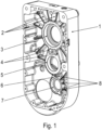
Figur 1 ist ein erstes Gehäuseteil 1 des erfindungsgemäßen Getriebes in Schrägansicht dargestellt. - In der
Figur 2 ist das erste Gehäuseteil 1 aus einer anderen Blickrichtung in Schrägansicht dargestellt. - In der
Figur 3 ist ein zweites Gehäuseteil 30 des erfindungsgemäßen Getriebes in Schrägansicht dargestellt. - In der
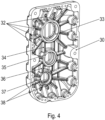
Figur 4 ist das zweite Gehäuseteil 30 aus einer anderen Blickrichtung in Schrägansicht dargestellt. - In der
Figur 5 ist das erste Gehäuseteil 1 in Draufsicht dargestellt. - In der
Figur 6 ist das zweite Gehäuseteil 30 in Draufsicht dargestellt. - Wie in den Figuren dargestellt, weist das erste Gehäuseteil 1 Lageraufnahmen (3, 5, 7) auf, in denen jeweils ein Lager zur Lagerung einer Welle des Getriebes aufnehmbar ist.
- Die mittels der Lager in den Lageraufnahmen (3, 5, 7) gelagerten Wellen sind alle zueinander parallel ausgereichtet.
- Dabei ist die jeweilige Welle entweder eintreibende Welle, abtreibende Welle oder fungiert als Zwischenwelle. In jedem Fall ist zumindest ein jeweiliges Verzahnungsteil des Getriebes drehfest mit der jeweiligen Welle verbunden.
- Das erste Gehäuseteil 1 ist dabei grob gesprochen topfförmig ausgeführt, wobei das erste Gehäuseteil 1 dabei eine Bodenseite aufweist, in welchem die Lageraufnahmen (3, 5, 7) als durchgehende Ausnehmungen, also als durch die Bodenseite, durchgehende Ausnehmungen, in welcher die Lager aufnehmbar sind.
- Berandet ist die Bodenseite durch eine erhabene umlaufende Wand, an welcher die Wand eines zweiten Gehäuseteils anliegt, das ebenfalls topfförmig ausgeführt ist, wobei die Wand des zweiten Gehäuseteils die Bodenseite des zweiten Gehäuseteils 30 berandet und ebenfalls den Rand des Bodenteils des zweiten Gehäuseteils 30 umläuft.
- Das erste Gehäuseteil 1 ist mittels einer an der dem zweiten Gehäuseteil 30 zugewandten Stirnfläche der umlaufenden Wand des ersten Gehäuseteils 1 angeordneten Dichtung abgedichtet verbunden mit dem zweiten Gehäuseteil 30.
- Der Innenraum des Getriebes ist mit Schmieröl zumindest teilweise befüllt.
- An jeder Lageraufnahme (3, 5, 7) des ersten Gehäuseteils 1 sind strahlenförmig sich erstreckende Rippen (2, 4, 6, 8) angeordnet. Dabei verläuft eine erste Sorte von Rippen (2, 8) jeweils von einer der Lageraufnahmen (3, 5, 7) bis zur Wand des ersten Gehäuseteils 1. Die axiale, also in Achsrichtung der Wellen, gemessene Höhe der Rippen (2, 4, 6, 8) ist gleich. Somit erstrecken sich also die Rippen (2, 4, 6, 8) alle vom Boden des ersten Gehäuseteils bis zu einer gemeinsamen axialen Position.
- Eine zweite Sorte von Rippen (4, 6) erstrecken sich nur von einer jeweiligen Lageraufnahme zu einer anderen Lageraufahme.
- Das Gehäuse des Getriebes ist also aus dem ersten und dem zweiten Gehäuseteil (1, 30) gebildet.
- Die Lageraufnahmen (3, 5, 7) erstrecken sich ebenfalls von der Bodenseite zur selben axialen Position wie auch die Rippen (2, 4, 6, 8).
- Die beiden Rippen 4, welche sich von der Lageraufnahme 3, insbesondere von der Lageraufnahem der abtreibenden Welle des Getriebes, zur Lageraufnahme 5, insbesondere Lageraufnahme der Zwischenwelle, erstrecken, sind voneinander beabstandet. Somit ist eine Vertiefung im ersten Gehäuseteil 1 gebildet, die von der Bodenseite des ersten Gehäuseteils 1 begrenzt wird und von den beiden Lageraufnahmen 3 und 5 sowie von den beiden Rippen 4, welche von der Lageraufnahme 3 zur Lageraufnahme 5 sich erstrecken.
- Die Rippen (2, 4, 6, 8) weisen eine im Wesentlichen konstante Wandstärke auf.
- Die umlaufende Wand weist an mehreren Stellen Verdickungen auf, in welche axial sich gerichtete Gewindebohrungen eingebracht sind, in welche Verbindungsschrauben einschraubbar sind, mit welchen das erste und das zweite Gehäuseteil (1, 30) miteinander verbindbar sind.
- Das zweite Gehäuseteil 30 ist entsprechend aufgebaut, hat also ebenfalls Lageraufnahmen (33, 35, 37), in welchen Lager zur Lagerung der Wellen aufnehmbar sind. Wiederum erstrecken sich von den Lageraufnahmen (33, 35, 37) Rippen (32, 38) erster Art zur umlaufenden Wand des zweiten Gehäuseteils 30 oder erstrecken sich Rippen (34, 36) zweiter Art von einer der Lageraufnahmen (33, 35, 37) zu einer anderen der Lageraufnahmen (33, 35, 37).
- Die beiden Rippen 34, welche sich von der Lageraufnahme 33, insbesondere von der Lageraufnahme der abtreibenden Welle des Getriebes, zur Lageraufnahme 35, insbesondere Lageraufnahme der Zwischenwelle, erstrecken, sind voneinander beabstandet. Somit ist eine Vertiefung im zweiten Gehäuseteil 30 gebildet, die von der Bodenseite des zweiten Gehäuseteils 30 begrenzt wird und von den beiden Lageraufnahmen 33 und 35 sowie von den beiden Rippen 34, welche von der Lageraufnahme 33 zur Lageraufnahme 35 sich erstrecken.
- Gleiches gilt für die von den Rippen 36 und den Lageraufnahmen 35 und 37 sowie von dem Boden des zweiten Gehäuseteils 30 begrenzten Vertiefung, der der entsprechenden Vertiefung des ersten Gehäuseteils 1 axial gegenüber angeordnet ist.
- Die Rippen (32, 34, 36, 38) weisen eine im Wesentlichen konstante Wandstärke auf. Somit ist nur wenig Material für die Gehäuseteile (1, 30) notwendig und eine effektive Wärmeabfuhr vom Schmieröl an die Umgebungsluft ermöglicht. Denn einerseits dienen die Rippen der aufspreizung der von den Lagern erzeugten Wärme, indem die von den Lageraufnahmen an die Rippen abgeführte Wärme an die Bodenseite verteilt wird, wobei in Betriebszuständen, in welchen das Schmieröl noch eine niedrigere Temperatur aufweist als die jeweilige Lageraufnahme, die Wärme zumindest teilweise ans Schmieröl weitergeleitet wird, von wo sie dann infolge der schnellen Transportgeschwindigkeiten des Schmieröls auf alle Bodenseiten und Wandbereiche verteilt wird. Andererseits wird in Betriebszuständen, in welchen die Temperatur des Schmieröls höher ist als die Temperatur der Rippen, die Wärme von den Rippen aufgespreizt und verteilt. Wenn die Lageraufnahmen eine niedrigere Temperatur aufweisen als das Schmieröl, ist sogar ein Einsammeln von Wärme mittels der Rippen und zumindest teilweises Zuleiten an das jeweilige Lagerschild ermöglicht.
- Die umlaufende Wand weist an mehreren Stellen Verdickungen auf, in welche axial sich gerichtete Bohrungen eingebracht sind, durch welche Verbindungsschrauben durchführbar sind, mit welchen das erste und das zweite Gehäuseteil (1, 30) miteinander verbindbar sind.
- Vorzugsweise sind beide Gehäuseteile (1, 30) als Metallteil gefertigt, insbesondere Spritzgussteil gefertigt, insbesondere als Aluminiumspritzgussteil.
-
- 1
- erstes Gehäuseteil
- 2
- Rippe
- 3
- Lageraufnahme
- 4
- Verbindungsrippe
- 5
- Lageraufnahme
- 6
- Rippe
- 7
- Lageraufnahme
- 8
- Rippe
- 30
- zweites Gehäuseteil
- 31
- Vertiefung
- 32
- Rippe
- 33
- Lageraufnahme
- 34
- Verbindungsrippe
- 35
- Lageraufnahme
- 36
- Rippe
- 37
- Lageraufnahme
- 38
- Rippe
Claims (6)
- Getriebe, aufweisend ein zumindest ein erstes und ein zweites Gehäuseteil (1, 30) aufweisendes Gehäuse,wobei im jeweiligen Gehäuseteil (1, 30) jeweils eine erste und zumindest eine weitere Lageraufnahme (3, 5, 7, 33, 35, 37) ausgebildet ist, wobei in der jeweiligen Lageraufnahme jeweils ein jeweiliges Lager einer jeweiligen Welle des Getriebes aufgenommen ist,wobei an zumindest der jeweiligen ersten Lageraufnahme (3, 5, 7, 33, 35, 37) an der Innenseite des jeweiligen Gehäuseteils (1, 30) Rippen (2, 4, 6, 8, 32, 34, 36,38) strahlenförmig ausgeformt sind,wobei die Rippen (2, 4, 6, 8, 32, 34, 36,38) sich strahlenförmig, also nur in radialer Richtung von der Mittelachse oder Symmetrieachse der jeweiligen ersten Lageraufnahme (3, 5, 7, 33, 35, 37) aus, erstrecken,wobei die Rippen (2, 4, 6, 8, 32, 34, 36,38) sich von der jeweiligen ersten Lageraufnahme (3, 5, 7, 33, 35, 37) bis zu einer jeweiligen Wand erstrecken,wobei die eine der beiden Wände am Rand einer Bodenseite des ersten Gehäuseteils (1) umlaufend ausgeformt ist,und/oder zumindest eine oder mehrere der Rippen (2, 4, 6, 8, 32, 34, 36,38) sich bis zu der jeweiligen weiteren Lageraufnahme (3, 5, 7, 33, 35, 37) erstrecken,wobei alle Rippen (2, 4, 6, 8, 32, 34, 36,38) des ersten Gehäuseteils (1) sich nur bis zu einer ersten, insbesondere einzigen, axialen Position erstrecken,wobei alle Rippen (2, 4, 6, 8, 32, 34, 36,38) des zweiten Gehäuseteils (30) sich nur bis zu einer anderen, insbesondere einzigen, axialen Position erstrecken,dadurch gekennzeichnet, dassdie Rippen (2, 4, 6, 8, 32, 34, 36,38) des ersten Gehäuseteils (1) von den Rippen (2, 4, 6, 8, 32, 34, 36,38) des zweiten Gehäuseteils (30) axial beabstandet sind,wobei das erste Gehäuseteil (1) topfförmig ausgeführt ist, wobei eine Bodenseite des ersten Gehäuseteils (1) berandet ist durch eine erhabene umlaufende Wand, an welcher eine Wand des zweiten Gehäuseteils (30) anliegt, das ebenfalls topfförmig ausgeführt ist, wobei die Wand des zweiten Gehäuseteils (30) die Bodenseite des zweiten Gehäuseteils (30) berandet und ebenfalls den Rand des Bodenteils des zweiten Gehäuseteils (30) umläuft,wobei das erste Gehäuseteil (1) mittels einer an der dem zweiten Gehäuseteil (30) zugewandten Stirnfläche der umlaufenden Wand des ersten Gehäuseteils (1) angeordneten Dichtung abgedichtet verbunden mit dem zweiten Gehäuseteil (30) ist,wobei in der Bodenseite des ersten Gehäuseteils (1) die Lageraufnahmen (3, 5, 7) als durchgehende Ausnehmungen, also als durch die Bodenseite des ersten Gehäuseteils (1) durchgehende Ausnehmungen, in welcher die Lager aufnehmbar sind, ausgeführt sind,wobei eine oder mehrere Lageraufnahmen (3, 5, 7, 33, 35, 37) des ersten oder zweiten Gehäuseteils (1, 30) mittels eines auf der Außenseite des jeweiligen Gehäuseteils (1, 30) angebrachten Getriebedeckels abgedeckt sind.
- Getriebe nach Anspruch 1,
dadurch gekennzeichnet, dass
die Wand im Übergangsbereich zwischen Wand und jeweiliger Rippen (2, 4, 6, 8, 32, 34, 36,38) verdickt ausgeführt ist und in dieser Verdickung jeweils eine Axialbohrung angeordnet ist. - Getriebe nach mindestens einem der vorangegangenen Ansprüche,
dadurch gekennzeichnet, dass
die Wandstärke der Rippen (2, 4, 6, 8, 32, 34, 36,38) konstant ist, insbesondere wobei alle Rippen (2, 4, 6, 8, 32, 34, 36,38) dieselbe Wandstärke aufweisen. - Getriebe nach mindestens einem der vorangegangenen Ansprüche,
dadurch gekennzeichnet, dass
jede Lageraufnahme (3, 5, 7, 33, 35, 37) als hohlzylindrische aus der Bodenseite in den Innenraum des Getriebes hervorstehende Ausformung ausgebildet ist, wobei im Hohlzylinder ein Lager, insbesondere Kugellager, aufgenommen ist, welches eine Welle lagert, mit der zumindest ein Verzahnungsteil drehfest verbunden ist. - Getriebe nach mindestens einem der vorangegangenen Ansprüche,
dadurch gekennzeichnet, dass
das Gehäuseteil (1, 30) jeweils als Gussteil, insbesondere Aluminium-Druckgussteil, herstellbar ist. - Getriebe nach mindestens einem der vorangegangenen Ansprüche,
dadurch gekennzeichnet, dass
zwei voneinander beabstandete Rippen (2, 4, 6, 8, 32, 34, 36,38) von der jeweiligen ersten Lageraufnahme (3, 5, 7, 33, 35, 37) zu der jeweiligen weiteren Lageraufnahme (3, 5, 7, 33, 35, 37) sich erstrecken und somit eine Vertiefung (31) im ersten Gehäuseteil (1) gebildet ist, welche von den beiden voneinander beabstandeten Rippen (2, 4, 6, 8, 32, 34, 36,38), den beiden Lageraufnahmen (3, 5, 7, 33, 35, 37) und der Bodenseite des Getriebes begrenzt ist.
Applications Claiming Priority (3)
| Application Number | Priority Date | Filing Date | Title |
|---|---|---|---|
| DE102015013900 | 2015-10-27 | ||
| DE102015016227.6A DE102015016227A1 (de) | 2015-10-27 | 2015-12-16 | Getriebe , aufweisend ein zumindest ein erstes und ein zweites Gehäuseteil aufweisendes Gehäuse |
| PCT/EP2016/025120 WO2017071819A1 (de) | 2015-10-27 | 2016-10-18 | Getriebe, aufweisend ein zumindest ein erstes und ein zweites gehäuseteil aufweisendes gehäuse |
Publications (3)
| Publication Number | Publication Date |
|---|---|
| EP3368795A1 EP3368795A1 (de) | 2018-09-05 |
| EP3368795B1 EP3368795B1 (de) | 2020-12-09 |
| EP3368795B2 true EP3368795B2 (de) | 2023-11-22 |
Family
ID=58490085
Family Applications (1)
| Application Number | Title | Priority Date | Filing Date |
|---|---|---|---|
| EP16784798.7A Active EP3368795B2 (de) | 2015-10-27 | 2016-10-18 | Getriebe, aufweisend ein zumindest ein erstes und ein zweites gehäuseteil aufweisendes gehäuse |
Country Status (3)
| Country | Link |
|---|---|
| EP (1) | EP3368795B2 (de) |
| DE (1) | DE102015016227A1 (de) |
| WO (1) | WO2017071819A1 (de) |
Families Citing this family (5)
| Publication number | Priority date | Publication date | Assignee | Title |
|---|---|---|---|---|
| US11280396B2 (en) * | 2019-11-13 | 2022-03-22 | Rolls-Royce Corporation | Fire resistant gearbox housing |
| CN111075910A (zh) * | 2020-01-09 | 2020-04-28 | 精进电动科技(菏泽)有限公司 | 一种减速器箱体结构 |
| EP4237704A1 (de) * | 2020-10-30 | 2023-09-06 | Sew-Eurodrive GmbH & Co. KG | Getriebe mit getriebegehäuse, aufweisend ein gehäuseteil und mit dem gehäuseteil verbundenes deckelteil |
| CN112377599A (zh) * | 2020-11-20 | 2021-02-19 | 马鞍山市龙腾机电科技有限公司 | 一种用于立体停车位变速箱的高强度壳体及其生产工艺 |
| WO2025246252A1 (zh) * | 2024-05-28 | 2025-12-04 | 烟台杰瑞石油服务集团股份有限公司 | 减速箱及减速箱箱体 |
Citations (6)
| Publication number | Priority date | Publication date | Assignee | Title |
|---|---|---|---|---|
| DE19652834B4 (de) † | 1995-12-19 | 2004-05-13 | Sumitomo Heavy Industries, Ltd. | Geschwindigkeitswechselgetriebevorrichtung |
| DE102004033574A1 (de) † | 2004-03-12 | 2005-10-06 | Röchling Getriebe OHG | Getriebe |
| US7052429B1 (en) † | 2002-01-31 | 2006-05-30 | Hydro-Gear Limited Partnership | Internal expansion tank for hydrostatic transaxle |
| CN203082180U (zh) † | 2013-01-22 | 2013-07-24 | 重庆宗申发动机制造有限公司 | 一种电动三轮车用差速电机 |
| CN104179948A (zh) † | 2014-08-15 | 2014-12-03 | 丹阳荣嘉精密机械有限公司 | 一种齿轮箱箱盖 |
| CN104196984A (zh) † | 2014-08-15 | 2014-12-10 | 丹阳荣嘉精密机械有限公司 | 一种齿轮箱壳体 |
Family Cites Families (5)
| Publication number | Priority date | Publication date | Assignee | Title |
|---|---|---|---|---|
| US8790200B2 (en) * | 2010-03-11 | 2014-07-29 | Les Distributions Masterfab Inc. | Safety guard assembly for transmission mechanisms |
| DE102010053027B4 (de) * | 2010-12-02 | 2013-03-21 | Sew-Eurodrive Gmbh & Co. Kg | Wellenadaptereinheit, Getriebe und Antriebseinheit |
| US8911312B2 (en) * | 2011-10-06 | 2014-12-16 | Kawasaki Jukogyo Kabushiki Kaisha | Belt type continuously variable transmission |
| DE102012012140A1 (de) * | 2012-06-20 | 2013-12-24 | Robert Bosch Gmbh | Gehäuse für ein Getriebe |
| SE537741C2 (sv) * | 2013-11-22 | 2015-10-06 | Scania Cv Ab | Växellåda |
-
2015
- 2015-12-16 DE DE102015016227.6A patent/DE102015016227A1/de active Pending
-
2016
- 2016-10-18 EP EP16784798.7A patent/EP3368795B2/de active Active
- 2016-10-18 WO PCT/EP2016/025120 patent/WO2017071819A1/de not_active Ceased
Patent Citations (6)
| Publication number | Priority date | Publication date | Assignee | Title |
|---|---|---|---|---|
| DE19652834B4 (de) † | 1995-12-19 | 2004-05-13 | Sumitomo Heavy Industries, Ltd. | Geschwindigkeitswechselgetriebevorrichtung |
| US7052429B1 (en) † | 2002-01-31 | 2006-05-30 | Hydro-Gear Limited Partnership | Internal expansion tank for hydrostatic transaxle |
| DE102004033574A1 (de) † | 2004-03-12 | 2005-10-06 | Röchling Getriebe OHG | Getriebe |
| CN203082180U (zh) † | 2013-01-22 | 2013-07-24 | 重庆宗申发动机制造有限公司 | 一种电动三轮车用差速电机 |
| CN104179948A (zh) † | 2014-08-15 | 2014-12-03 | 丹阳荣嘉精密机械有限公司 | 一种齿轮箱箱盖 |
| CN104196984A (zh) † | 2014-08-15 | 2014-12-10 | 丹阳荣嘉精密机械有限公司 | 一种齿轮箱壳体 |
Non-Patent Citations (6)
| Title |
|---|
| Feldhusen (Hrsg.), "Dubbel", Springer Verlag, 2011, Ed. 23.Auflage † |
| Köhler et al., "Köhler/Rögnitz Maschinenteile 2", Vieweg+TeubnerVerlag, 2008, Ed. 10. Auflage † |
| S. 468 aus „Maschinenelemente" (K.-H. Decker; Carl Hanser Verlag, 18. Auflage, 2011) † |
| S. 489 aus „Roloff/Matek Maschinenelemente" (H. Wittel, D. Muhs,D. Jannasch, J. Voßiek; 20. Auflage,Vieweg+Teubner Verlag,2011) † |
| S. 619 aus „Maschinenelemente" (G. Niemann, H. Winter, B.-R.Höhn; Springer-Verlag, 3 Auflage, 2001) † |
| Wikipedia: „Lagerungskonzepte". † |
Also Published As
| Publication number | Publication date |
|---|---|
| EP3368795A1 (de) | 2018-09-05 |
| EP3368795B1 (de) | 2020-12-09 |
| DE102015016227A1 (de) | 2017-04-27 |
| WO2017071819A1 (de) | 2017-05-04 |
Similar Documents
| Publication | Publication Date | Title |
|---|---|---|
| EP3368795B2 (de) | Getriebe, aufweisend ein zumindest ein erstes und ein zweites gehäuseteil aufweisendes gehäuse | |
| EP3022465B1 (de) | Getriebe mit einem ersten und einem zweiten gehäuseteil | |
| DE102013018710B4 (de) | Getriebe mit Gehäuse | |
| EP2636128B1 (de) | Elektromotor, bausatz und verfahren zur herstellung | |
| DE102013018713B4 (de) | Getriebe mit Gehäuse | |
| DE102013018711B4 (de) | Getriebe mit Gehäuse | |
| DE102005013841B4 (de) | Zylinderblockaufbau für einen Motor | |
| DE202007017040U1 (de) | Zahnrad und dieses verwendendes Getriebe | |
| EP3714163B1 (de) | Kompressor | |
| DE102010053027A1 (de) | Wellenadaptereinheit, Getriebe und Antriebseinheit | |
| EP4176182A1 (de) | Getriebe mit gehäuse, welches ein unterteil und ein deckelteil, aufweist | |
| DE102012005529B4 (de) | Antrieb mit einer Welle | |
| DE102020003549A1 (de) | Getriebemotor, insbesondere einer Getriebemotorbaureihe, mit Adapterteil | |
| DE102014009317B4 (de) | Antrieb | |
| DE102012008653A1 (de) | Getriebe mit Getriebegehäuseteil mit an seiner Oberfläche angeordneten Gehäusetaschen oder Vertiefungen | |
| DE19610872C1 (de) | Zylinderkurbelgehäuse für eine Brennkraftmaschine | |
| EP3548774A1 (de) | Getriebe mit einem gehäuse, welches ein unteres gehäuseteil aufweist, auf welches ein oberes gehäuseteil aufgesetzt ist | |
| DE102019004393A1 (de) | Getriebe mit Gehäuseteil und Verfahren zum Herstellen eines Getriebes | |
| EP2515002B1 (de) | Getriebegehäuse | |
| EP3502474B1 (de) | Kompressor | |
| DE102024000151A1 (de) | Getriebe mit einem Gehäuse | |
| DE102008008192A1 (de) | Lagerung | |
| DE102024000150A1 (de) | Getriebe mit einem Gehäuse | |
| EP4508347A1 (de) | Getriebe mit einem ersten gehäuseteil und einem zweiten gehäuseteil |
Legal Events
| Date | Code | Title | Description |
|---|---|---|---|
| STAA | Information on the status of an ep patent application or granted ep patent |
Free format text: STATUS: UNKNOWN |
|
| STAA | Information on the status of an ep patent application or granted ep patent |
Free format text: STATUS: THE INTERNATIONAL PUBLICATION HAS BEEN MADE |
|
| PUAI | Public reference made under article 153(3) epc to a published international application that has entered the european phase |
Free format text: ORIGINAL CODE: 0009012 |
|
| STAA | Information on the status of an ep patent application or granted ep patent |
Free format text: STATUS: REQUEST FOR EXAMINATION WAS MADE |
|
| 17P | Request for examination filed |
Effective date: 20180528 |
|
| AK | Designated contracting states |
Kind code of ref document: A1 Designated state(s): AL AT BE BG CH CY CZ DE DK EE ES FI FR GB GR HR HU IE IS IT LI LT LU LV MC MK MT NL NO PL PT RO RS SE SI SK SM TR |
|
| AX | Request for extension of the european patent |
Extension state: BA ME |
|
| DAV | Request for validation of the european patent (deleted) | ||
| DAX | Request for extension of the european patent (deleted) | ||
| STAA | Information on the status of an ep patent application or granted ep patent |
Free format text: STATUS: EXAMINATION IS IN PROGRESS |
|
| 17Q | First examination report despatched |
Effective date: 20191204 |
|
| GRAP | Despatch of communication of intention to grant a patent |
Free format text: ORIGINAL CODE: EPIDOSNIGR1 |
|
| STAA | Information on the status of an ep patent application or granted ep patent |
Free format text: STATUS: GRANT OF PATENT IS INTENDED |
|
| INTG | Intention to grant announced |
Effective date: 20200709 |
|
| RAP1 | Party data changed (applicant data changed or rights of an application transferred) |
Owner name: SEW-EURODRIVE GMBH & CO. KG |
|
| GRAS | Grant fee paid |
Free format text: ORIGINAL CODE: EPIDOSNIGR3 |
|
| GRAA | (expected) grant |
Free format text: ORIGINAL CODE: 0009210 |
|
| STAA | Information on the status of an ep patent application or granted ep patent |
Free format text: STATUS: THE PATENT HAS BEEN GRANTED |
|
| AK | Designated contracting states |
Kind code of ref document: B1 Designated state(s): AL AT BE BG CH CY CZ DE DK EE ES FI FR GB GR HR HU IE IS IT LI LT LU LV MC MK MT NL NO PL PT RO RS SE SI SK SM TR |
|
| REG | Reference to a national code |
Ref country code: GB Ref legal event code: FG4D Free format text: NOT ENGLISH |
|
| REG | Reference to a national code |
Ref country code: AT Ref legal event code: REF Ref document number: 1343782 Country of ref document: AT Kind code of ref document: T Effective date: 20201215 Ref country code: CH Ref legal event code: EP |
|
| REG | Reference to a national code |
Ref country code: DE Ref legal event code: R096 Ref document number: 502016011948 Country of ref document: DE |
|
| REG | Reference to a national code |
Ref country code: IE Ref legal event code: FG4D Free format text: LANGUAGE OF EP DOCUMENT: GERMAN |
|
| PG25 | Lapsed in a contracting state [announced via postgrant information from national office to epo] |
Ref country code: GR Free format text: LAPSE BECAUSE OF FAILURE TO SUBMIT A TRANSLATION OF THE DESCRIPTION OR TO PAY THE FEE WITHIN THE PRESCRIBED TIME-LIMIT Effective date: 20210310 Ref country code: FI Free format text: LAPSE BECAUSE OF FAILURE TO SUBMIT A TRANSLATION OF THE DESCRIPTION OR TO PAY THE FEE WITHIN THE PRESCRIBED TIME-LIMIT Effective date: 20201209 Ref country code: NO Free format text: LAPSE BECAUSE OF FAILURE TO SUBMIT A TRANSLATION OF THE DESCRIPTION OR TO PAY THE FEE WITHIN THE PRESCRIBED TIME-LIMIT Effective date: 20210309 Ref country code: RS Free format text: LAPSE BECAUSE OF FAILURE TO SUBMIT A TRANSLATION OF THE DESCRIPTION OR TO PAY THE FEE WITHIN THE PRESCRIBED TIME-LIMIT Effective date: 20201209 |
|
| PG25 | Lapsed in a contracting state [announced via postgrant information from national office to epo] |
Ref country code: SE Free format text: LAPSE BECAUSE OF FAILURE TO SUBMIT A TRANSLATION OF THE DESCRIPTION OR TO PAY THE FEE WITHIN THE PRESCRIBED TIME-LIMIT Effective date: 20201209 Ref country code: BG Free format text: LAPSE BECAUSE OF FAILURE TO SUBMIT A TRANSLATION OF THE DESCRIPTION OR TO PAY THE FEE WITHIN THE PRESCRIBED TIME-LIMIT Effective date: 20210309 Ref country code: LV Free format text: LAPSE BECAUSE OF FAILURE TO SUBMIT A TRANSLATION OF THE DESCRIPTION OR TO PAY THE FEE WITHIN THE PRESCRIBED TIME-LIMIT Effective date: 20201209 |
|
| REG | Reference to a national code |
Ref country code: NL Ref legal event code: MP Effective date: 20201209 |
|
| PG25 | Lapsed in a contracting state [announced via postgrant information from national office to epo] |
Ref country code: HR Free format text: LAPSE BECAUSE OF FAILURE TO SUBMIT A TRANSLATION OF THE DESCRIPTION OR TO PAY THE FEE WITHIN THE PRESCRIBED TIME-LIMIT Effective date: 20201209 Ref country code: NL Free format text: LAPSE BECAUSE OF FAILURE TO SUBMIT A TRANSLATION OF THE DESCRIPTION OR TO PAY THE FEE WITHIN THE PRESCRIBED TIME-LIMIT Effective date: 20201209 |
|
| REG | Reference to a national code |
Ref country code: LT Ref legal event code: MG9D |
|
| PG25 | Lapsed in a contracting state [announced via postgrant information from national office to epo] |
Ref country code: PT Free format text: LAPSE BECAUSE OF FAILURE TO SUBMIT A TRANSLATION OF THE DESCRIPTION OR TO PAY THE FEE WITHIN THE PRESCRIBED TIME-LIMIT Effective date: 20210409 Ref country code: SK Free format text: LAPSE BECAUSE OF FAILURE TO SUBMIT A TRANSLATION OF THE DESCRIPTION OR TO PAY THE FEE WITHIN THE PRESCRIBED TIME-LIMIT Effective date: 20201209 Ref country code: RO Free format text: LAPSE BECAUSE OF FAILURE TO SUBMIT A TRANSLATION OF THE DESCRIPTION OR TO PAY THE FEE WITHIN THE PRESCRIBED TIME-LIMIT Effective date: 20201209 Ref country code: CZ Free format text: LAPSE BECAUSE OF FAILURE TO SUBMIT A TRANSLATION OF THE DESCRIPTION OR TO PAY THE FEE WITHIN THE PRESCRIBED TIME-LIMIT Effective date: 20201209 Ref country code: EE Free format text: LAPSE BECAUSE OF FAILURE TO SUBMIT A TRANSLATION OF THE DESCRIPTION OR TO PAY THE FEE WITHIN THE PRESCRIBED TIME-LIMIT Effective date: 20201209 Ref country code: SM Free format text: LAPSE BECAUSE OF FAILURE TO SUBMIT A TRANSLATION OF THE DESCRIPTION OR TO PAY THE FEE WITHIN THE PRESCRIBED TIME-LIMIT Effective date: 20201209 Ref country code: LT Free format text: LAPSE BECAUSE OF FAILURE TO SUBMIT A TRANSLATION OF THE DESCRIPTION OR TO PAY THE FEE WITHIN THE PRESCRIBED TIME-LIMIT Effective date: 20201209 |
|
| PG25 | Lapsed in a contracting state [announced via postgrant information from national office to epo] |
Ref country code: PL Free format text: LAPSE BECAUSE OF FAILURE TO SUBMIT A TRANSLATION OF THE DESCRIPTION OR TO PAY THE FEE WITHIN THE PRESCRIBED TIME-LIMIT Effective date: 20201209 |
|
| REG | Reference to a national code |
Ref country code: DE Ref legal event code: R026 Ref document number: 502016011948 Country of ref document: DE |
|
| PLBI | Opposition filed |
Free format text: ORIGINAL CODE: 0009260 |
|
| PG25 | Lapsed in a contracting state [announced via postgrant information from national office to epo] |
Ref country code: IS Free format text: LAPSE BECAUSE OF FAILURE TO SUBMIT A TRANSLATION OF THE DESCRIPTION OR TO PAY THE FEE WITHIN THE PRESCRIBED TIME-LIMIT Effective date: 20210409 |
|
| 26 | Opposition filed |
Opponent name: ZF FRIEDRICHSHAFEN AG Effective date: 20210908 |
|
| PG25 | Lapsed in a contracting state [announced via postgrant information from national office to epo] |
Ref country code: AL Free format text: LAPSE BECAUSE OF FAILURE TO SUBMIT A TRANSLATION OF THE DESCRIPTION OR TO PAY THE FEE WITHIN THE PRESCRIBED TIME-LIMIT Effective date: 20201209 |
|
| PLAX | Notice of opposition and request to file observation + time limit sent |
Free format text: ORIGINAL CODE: EPIDOSNOBS2 |
|
| PG25 | Lapsed in a contracting state [announced via postgrant information from national office to epo] |
Ref country code: DK Free format text: LAPSE BECAUSE OF FAILURE TO SUBMIT A TRANSLATION OF THE DESCRIPTION OR TO PAY THE FEE WITHIN THE PRESCRIBED TIME-LIMIT Effective date: 20201209 Ref country code: SI Free format text: LAPSE BECAUSE OF FAILURE TO SUBMIT A TRANSLATION OF THE DESCRIPTION OR TO PAY THE FEE WITHIN THE PRESCRIBED TIME-LIMIT Effective date: 20201209 |
|
| PG25 | Lapsed in a contracting state [announced via postgrant information from national office to epo] |
Ref country code: ES Free format text: LAPSE BECAUSE OF FAILURE TO SUBMIT A TRANSLATION OF THE DESCRIPTION OR TO PAY THE FEE WITHIN THE PRESCRIBED TIME-LIMIT Effective date: 20201209 |
|
| PLBB | Reply of patent proprietor to notice(s) of opposition received |
Free format text: ORIGINAL CODE: EPIDOSNOBS3 |
|
| PLAB | Opposition data, opponent's data or that of the opponent's representative modified |
Free format text: ORIGINAL CODE: 0009299OPPO |
|
| REG | Reference to a national code |
Ref country code: CH Ref legal event code: PL |
|
| PG25 | Lapsed in a contracting state [announced via postgrant information from national office to epo] |
Ref country code: IS Free format text: LAPSE BECAUSE OF FAILURE TO SUBMIT A TRANSLATION OF THE DESCRIPTION OR TO PAY THE FEE WITHIN THE PRESCRIBED TIME-LIMIT Effective date: 20210409 |
|
| R26 | Opposition filed (corrected) |
Opponent name: ZF FRIEDRICHSHAFEN AG Effective date: 20210908 |
|
| REG | Reference to a national code |
Ref country code: BE Ref legal event code: MM Effective date: 20211031 |
|
| GBPC | Gb: european patent ceased through non-payment of renewal fee |
Effective date: 20211018 |
|
| PG25 | Lapsed in a contracting state [announced via postgrant information from national office to epo] |
Ref country code: MC Free format text: LAPSE BECAUSE OF FAILURE TO SUBMIT A TRANSLATION OF THE DESCRIPTION OR TO PAY THE FEE WITHIN THE PRESCRIBED TIME-LIMIT Effective date: 20201209 |
|
| PG25 | Lapsed in a contracting state [announced via postgrant information from national office to epo] |
Ref country code: LU Free format text: LAPSE BECAUSE OF NON-PAYMENT OF DUE FEES Effective date: 20211018 Ref country code: GB Free format text: LAPSE BECAUSE OF NON-PAYMENT OF DUE FEES Effective date: 20211018 Ref country code: BE Free format text: LAPSE BECAUSE OF NON-PAYMENT OF DUE FEES Effective date: 20211031 |
|
| PG25 | Lapsed in a contracting state [announced via postgrant information from national office to epo] |
Ref country code: LI Free format text: LAPSE BECAUSE OF NON-PAYMENT OF DUE FEES Effective date: 20211031 Ref country code: CH Free format text: LAPSE BECAUSE OF NON-PAYMENT OF DUE FEES Effective date: 20211031 |
|
| PG25 | Lapsed in a contracting state [announced via postgrant information from national office to epo] |
Ref country code: IE Free format text: LAPSE BECAUSE OF NON-PAYMENT OF DUE FEES Effective date: 20211018 |
|
| REG | Reference to a national code |
Ref country code: AT Ref legal event code: MM01 Ref document number: 1343782 Country of ref document: AT Kind code of ref document: T Effective date: 20211018 |
|
| PG25 | Lapsed in a contracting state [announced via postgrant information from national office to epo] |
Ref country code: AT Free format text: LAPSE BECAUSE OF NON-PAYMENT OF DUE FEES Effective date: 20211018 |
|
| PG25 | Lapsed in a contracting state [announced via postgrant information from national office to epo] |
Ref country code: HU Free format text: LAPSE BECAUSE OF FAILURE TO SUBMIT A TRANSLATION OF THE DESCRIPTION OR TO PAY THE FEE WITHIN THE PRESCRIBED TIME-LIMIT; INVALID AB INITIO Effective date: 20161018 |
|
| PG25 | Lapsed in a contracting state [announced via postgrant information from national office to epo] |
Ref country code: CY Free format text: LAPSE BECAUSE OF FAILURE TO SUBMIT A TRANSLATION OF THE DESCRIPTION OR TO PAY THE FEE WITHIN THE PRESCRIBED TIME-LIMIT Effective date: 20201209 |
|
| PUAH | Patent maintained in amended form |
Free format text: ORIGINAL CODE: 0009272 |
|
| STAA | Information on the status of an ep patent application or granted ep patent |
Free format text: STATUS: PATENT MAINTAINED AS AMENDED |
|
| 27A | Patent maintained in amended form |
Effective date: 20231122 |
|
| AK | Designated contracting states |
Kind code of ref document: B2 Designated state(s): AL AT BE BG CH CY CZ DE DK EE ES FI FR GB GR HR HU IE IS IT LI LT LU LV MC MK MT NL NO PL PT RO RS SE SI SK SM TR |
|
| REG | Reference to a national code |
Ref country code: DE Ref legal event code: R102 Ref document number: 502016011948 Country of ref document: DE |
|
| PG25 | Lapsed in a contracting state [announced via postgrant information from national office to epo] |
Ref country code: MK Free format text: LAPSE BECAUSE OF FAILURE TO SUBMIT A TRANSLATION OF THE DESCRIPTION OR TO PAY THE FEE WITHIN THE PRESCRIBED TIME-LIMIT Effective date: 20201209 |
|
| PG25 | Lapsed in a contracting state [announced via postgrant information from national office to epo] |
Ref country code: MT Free format text: LAPSE BECAUSE OF FAILURE TO SUBMIT A TRANSLATION OF THE DESCRIPTION OR TO PAY THE FEE WITHIN THE PRESCRIBED TIME-LIMIT Effective date: 20201209 |
|
| PGFP | Annual fee paid to national office [announced via postgrant information from national office to epo] |
Ref country code: IT Payment date: 20250922 Year of fee payment: 10 |
|
| PGFP | Annual fee paid to national office [announced via postgrant information from national office to epo] |
Ref country code: FR Payment date: 20250908 Year of fee payment: 10 |
|
| PG25 | Lapsed in a contracting state [announced via postgrant information from national office to epo] |
Ref country code: TR Free format text: LAPSE BECAUSE OF FAILURE TO SUBMIT A TRANSLATION OF THE DESCRIPTION OR TO PAY THE FEE WITHIN THE PRESCRIBED TIME-LIMIT Effective date: 20201209 |
|
| PGFP | Annual fee paid to national office [announced via postgrant information from national office to epo] |
Ref country code: DE Payment date: 20251031 Year of fee payment: 10 |