EP3368450B1 - Fördersystem, modulare förderkette und spritzgegossenes kunststoffkettemodul - Google Patents
Fördersystem, modulare förderkette und spritzgegossenes kunststoffkettemodul Download PDFInfo
- Publication number
- EP3368450B1 EP3368450B1 EP16801863.8A EP16801863A EP3368450B1 EP 3368450 B1 EP3368450 B1 EP 3368450B1 EP 16801863 A EP16801863 A EP 16801863A EP 3368450 B1 EP3368450 B1 EP 3368450B1
- Authority
- EP
- European Patent Office
- Prior art keywords
- portions
- wall
- hinge structure
- module
- thickness
- Prior art date
- Legal status (The legal status is an assumption and is not a legal conclusion. Google has not performed a legal analysis and makes no representation as to the accuracy of the status listed.)
- Active
Links
Images


Classifications
-
- B—PERFORMING OPERATIONS; TRANSPORTING
- B65—CONVEYING; PACKING; STORING; HANDLING THIN OR FILAMENTARY MATERIAL
- B65G—TRANSPORT OR STORAGE DEVICES, e.g. CONVEYORS FOR LOADING OR TIPPING, SHOP CONVEYOR SYSTEMS OR PNEUMATIC TUBE CONVEYORS
- B65G17/00—Conveyors having an endless traction element, e.g. a chain, transmitting movement to a continuous or substantially-continuous load-carrying surface or to a series of individual load-carriers; Endless-chain conveyors in which the chains form the load-carrying surface
- B65G17/06—Conveyors having an endless traction element, e.g. a chain, transmitting movement to a continuous or substantially-continuous load-carrying surface or to a series of individual load-carriers; Endless-chain conveyors in which the chains form the load-carrying surface having a load-carrying surface formed by a series of interconnected, e.g. longitudinal, links, plates, or platforms
- B65G17/08—Conveyors having an endless traction element, e.g. a chain, transmitting movement to a continuous or substantially-continuous load-carrying surface or to a series of individual load-carriers; Endless-chain conveyors in which the chains form the load-carrying surface having a load-carrying surface formed by a series of interconnected, e.g. longitudinal, links, plates, or platforms the surface being formed by the traction element
-
- B—PERFORMING OPERATIONS; TRANSPORTING
- B65—CONVEYING; PACKING; STORING; HANDLING THIN OR FILAMENTARY MATERIAL
- B65G—TRANSPORT OR STORAGE DEVICES, e.g. CONVEYORS FOR LOADING OR TIPPING, SHOP CONVEYOR SYSTEMS OR PNEUMATIC TUBE CONVEYORS
- B65G17/00—Conveyors having an endless traction element, e.g. a chain, transmitting movement to a continuous or substantially-continuous load-carrying surface or to a series of individual load-carriers; Endless-chain conveyors in which the chains form the load-carrying surface
- B65G17/06—Conveyors having an endless traction element, e.g. a chain, transmitting movement to a continuous or substantially-continuous load-carrying surface or to a series of individual load-carriers; Endless-chain conveyors in which the chains form the load-carrying surface having a load-carrying surface formed by a series of interconnected, e.g. longitudinal, links, plates, or platforms
- B65G17/08—Conveyors having an endless traction element, e.g. a chain, transmitting movement to a continuous or substantially-continuous load-carrying surface or to a series of individual load-carriers; Endless-chain conveyors in which the chains form the load-carrying surface having a load-carrying surface formed by a series of interconnected, e.g. longitudinal, links, plates, or platforms the surface being formed by the traction element
- B65G17/086—Conveyors having an endless traction element, e.g. a chain, transmitting movement to a continuous or substantially-continuous load-carrying surface or to a series of individual load-carriers; Endless-chain conveyors in which the chains form the load-carrying surface having a load-carrying surface formed by a series of interconnected, e.g. longitudinal, links, plates, or platforms the surface being formed by the traction element specially adapted to follow a curved path
-
- B—PERFORMING OPERATIONS; TRANSPORTING
- B65—CONVEYING; PACKING; STORING; HANDLING THIN OR FILAMENTARY MATERIAL
- B65G—TRANSPORT OR STORAGE DEVICES, e.g. CONVEYORS FOR LOADING OR TIPPING, SHOP CONVEYOR SYSTEMS OR PNEUMATIC TUBE CONVEYORS
- B65G17/00—Conveyors having an endless traction element, e.g. a chain, transmitting movement to a continuous or substantially-continuous load-carrying surface or to a series of individual load-carriers; Endless-chain conveyors in which the chains form the load-carrying surface
- B65G17/30—Details; Auxiliary devices
- B65G17/38—Chains or like traction elements; Connections between traction elements and load-carriers
- B65G17/40—Chains acting as load-carriers
Definitions
- the invention relates to a conveyor system comprising a conveyor chain having injection molded plastic chain modules.
- Such conveyor systems, such conveyor chains and such injection molded plastic chain modules are known and are utilized to form conveyor chains for conveying all sorts of products.
- the conveyor chain can comprise injection molded plastic chain modules, each of which comprise a substantially elongate conveying body defining a supporting surface for supporting products to be transported on said conveying body, and a hinge structure for hingedly connecting the plastic chain module with other modules, wherein the hinge structure is located at a lower side of the plastic chain module and comprises a first hinge structure portion defining a first hinge pin receiving space for receiving a hinge pin, wherein the hinge structure further comprises a second and a third hinge structure portion defining a second hinge pin receiving space and a third hinge pin receiving space, respectively, wherein said second and third hinge structure portions are interspaced to receive a first hinge structure portion of a consecutive chain module there between, wherein the substantially elongate conveying body comprises a central portion and two wing shaped portions substantially extending away from said central portion in respective lateral directions, bottom sides of said wing shaped portions being arranged to be supported by a guide track.
- the substantially elongate conveying body comprises a central portion and two wing shaped portions substantially extending
- the conveyor system may for instance also comprise a conveyor mat having a relatively large width with respect to the conveyor chain.
- a top run of the conveyor chain which chain can have a relatively small width with respect to a conveyor mat, can at least partly extend along a top run of a conveyor mat located at least partly substantially parallel to the top run of the chain. For instance by means of a transfer guide rail, products conveyed by the conveyor mat can be transferred to the conveyor chain or vice versa.
- the wing shaped portions of the substantially elongate conveying body of the injection molded plastic chain modules can be supported by a guide track, especially by wear strips or rails thereof.
- the top run of the conveyor mat can be supported by the same guide track or by a guide track having a top surface located substantially at the same height level as the height level of the guide track supporting the wing shaped portions of the chain modules.
- a respective part of a supporting surface of the conveyor chain formed by the supporting surfaces of interconnected chain modules of said chain can preferably be located at the same height level as a corresponding adjacent part of the supporting surface of the conveyor mat. Therefore, the height of the wing shaped portions of the conveyor chain modules is often substantially equal to the height of the conveyor mat modules and/or to the height of a substantially elongate conveying body of conveyor mat modules of said mat.
- conveyor mats usually have their hinge pins located in the substantially elongate conveying body of conveyor mat modules of said mat, said conveying bodies of said mats need a certain height, for instance a height between 4 mm and 35 mm, such as for instance about 8.7 mm or about 12.7 mm.
- the wing shaped portions of the conveyor chain modules often have corresponding heights, e.g. a height between 3 mm and 40 mm, preferably a height in a range ranging from 4 mm to 35 mm, such as for instance a height of about 4 mm, about 8.7 mm, or about 12.7 mm.
- the invention provides for an injection molded plastic chain module according to claim 1.
- the invention may aim to provide a conveyor system, which on the one hand can facilitate a relatively smooth transfer of products from a supporting surface of a conveyor mat of said system onto an adjacently located supporting surface of a conveyor chain of said system, or vice versa, whereas said conveyor system can on the other hand be produced in a relatively time and/or cost efficient manner, especially with respect to conventional conveyor systems having injection molded plastic chain modules with relatively thick plastic wing shaped portions having a thickness corresponding to the thickness of substantially elongate conveying bodies of conveyor mat modules of the conveyor mat of the conveyor system.
- the invention provides for a conveyor system comprising a modular conveyor chain having a plurality of injection molded plastic chain modules, wherein each of said injection molded plastic chain modules comprises a substantially elongate conveying body defining a supporting surface for supporting products to be transported on said conveying body, and a hinge structure for hingedly connecting the plastic chain module with other modules, wherein the hinge structure is located at a lower side of the plastic chain module, wherein the hinge structure comprises a first hinge structure portion, especially a hinge structure rear portion located at the trailing side of the module, which first hinge structure portion defines a first hinge pin receiving space for receiving a hinge pin, wherein the hinge structure further comprises a second hinge structure portion and a third hinge structure portion, especially two hinge structure front portions located at the leading side of the module, wherein said second and third hinge structure portions define a second hinge pin receiving space and a third hinge pin receiving space, respectively, wherein said second and third hinge structure portions are interspaced to receive a first hinge structure portion, especially a hinge structure rear portion, of a consecutive
- the invention can relate to an injection molded plastic chain module comprising a substantially elongate conveying body and a hinge structure located at a bottom side of the module for hingedly connecting a front and a rear side of the module with adjacent modules.
- the conveying body comprises two wing shaped portions extending laterally away from the hinge structure, and comprising a respective top plate portion that defines a part of a supporting surface for supporting products to be transported, wherein each of said top plate portions has a thickness of less than 1/3 of the total thickness of the respective wing shaped portion.
- each wing shaped portion comprises one or more downwardly extending supporting wall portions for supporting the respective top plate portion.
- Each wing shaped portion may thus comprise a multiple number of downwardly extending supporting wall portions.
- the module may merely consist of a plurality of relatively thin plate and/or wall portions, preferably all having a substantially equal thickness. It is noted that the term "relatively thin" in the context of said relatively thin plate portions and/or relatively thin wall portions, at least in embodiments, may be understood as meaning that substantially all of said plate and/or wall portions substantially have a thickness that is relatively thin with respect to the height or total thickness of the wing shaped portions of the substantially elongate conveying body of the chain module.
- substantially all of said relatively thin plate portions and/or relatively thin wall portions may substantially have a respective thickness being less than 1/3 of the thickness of the wing shaped portions, and preferably even may substantially have a respective thickness being at most 30%, at most 25%, or at most 20% of said wing shaped portion thickness.
- the term "relatively thin" in the context of said relatively thin plate portions and/or relatively thin wall portions may, at least in embodiments, be understood as meaning that substantially all of said relatively thin plate portions and/or relatively thin wall portions have a thickness that is relatively thin with respect to the width of the second hinge structure portion and/or the width of the third hinge structure portion, said respective hinge structure portion's width in particular being measured in the lateral direction of the chain module.
- substantially all of said relatively thin plate portions and/or relatively thin wall portions may substantially have a respective thickness being less than 40%, less than 35% or less than 30% of the width of the second hinge structure portion and/or of the width of the third hinge structure portion.
- the wing shaped portion of the conveying body can have a relatively large thickness, e.g. about 4, 8.7 or 12.7 mm, without the need of the top plate portion of said wing shaped portion to have such a relatively large thickness itself.
- a relatively large thickness e.g. about 4, 8.7 or 12.7 mm
- the injection molding can be relatively short, but also relatively little plastic material is needed.
- the injection molded plastic chain modules, and therefore the conveyor chain and the conveyor system as well can be produced in a relatively time efficient and cost efficient manner.
- the injection molded plastic chain module can be an integrally molded chain module.
- the chain module may thus be formed as single piece, and then thus not being assembled from multiple separately formed pieces.
- the supporting wall portions of a respective wing portion can comprise multiple, preferably substantially parallel, supporting wall portions that are interspaced with respect to each other such that an interspace between two adjacent, preferably substantially parallel, wall portions is wider than the thickness of each of said two wall portions.
- the width of the interspace can be at least 150%, preferably at least 200% or even more, of the thickness of the thickest of said two adjacent wall portions. It is noted that both of said two interspaced wall portions preferably may have the same thickness as the other one.
- the wing shaped portions can be formed as substantially hollow wing shaped portions. This is, for instance more than 50%, preferably more than 60%, such as for instance at least 70%, of the total volume of the wing shaped portion may be formed by one or more empty spaces, whereas less than 50%, preferably less than 40%, such as for instance at most 30%, of the total volume of the wing shaped portion is formed by plastic material.
- the wing shaped portion can substantially consist of a plurality of relatively thin plate and/or wall portions.
- all of said plate portions and/or wall portions can have substantially the same thickness.
- the whole injection molded plastic chain module can substantially consist of a plurality of relatively thin plate and/or wall portions, preferably all having a substantially equal thickness.
- “having substantially the same thickness” and/or “having a substantially equal thickness” may at least be considered as meaning that the thickness of the plate and/or wall portions differ from each other to such a small extent that the thickness of the thickest plate or wall portion is less than 250%, preferably less than 200% or less than 150%, more preferably less than 120%, even more preferably less than 115%, such as for instance at most 110% or 105%, of the thickness of the thinnest plate and/or wall portion.
- the cooling time can be relatively short, as a result of which the injection molded plastic chain module can be ejected from its mold relatively quickly, thereby contributing to a relatively short injection molding cycle time.
- the present invention also relates to a conveyor chain for transporting products.
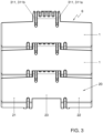
- a hinge structure 3 of the module can be located at a lower side 10 of the plastic chain module 1, e.g. a side located opposite of a top surface which may define a supporting surface 20 for supporting products to be conveyed during at least a part of a top run of the conveyor chain 6.
- the hinge structure 3, which can be extending downwardly from a substantially elongate conveying body 2, can be located at least partly between said two elongated guides 71 and can for instance be arranged to prevent lateral movement of the modules 1 and/or the chain 6.
- the conveyor system 5 can comprise a conveyor mat 8, which for instance can comprise multiple interconnected conveyor mat modules 80.
- the modules 80 of the conveyor mat 8 may have a relatively large width 81 with respect to the width 61 of the conveyor chain 6.
- a top run of the conveyor chain 6 can at least partly extend along a top run of the conveyor mat 8 located at least partly substantially parallel to the top run of the chain. This may for instance be done to allow products transported by the mat 8 to be transferred to the chain 6 or vice versa.
- the chain 6 may move at a higher speed that the mat 8.
- the conveyor chain 6, which advantageously can be a side-flexing conveyor chain designed to convey products along a track having one or more arcuate sections, may be arranged to move products in a direction away from the conveyor mat 8.
- the conveyor system 5 may comprise track means 7b or guide means 7b, e.g. comprising a table, to guide and/or support a top run of the conveyor mat 8.
- a top surface or a so-called guide surface 70b, especially a substantially horizontally oriented top surface 70b, may be formed by any suitable means, e.g. at least partly by multiple elongated guides 71b and/or top surfaces thereof. It is noted that a said track or guide means 7b for supporting and/or guiding a top run of the mat 8 may for instance at least partly be integrated with the track or guide means 7 for supporting and/or guiding the conveyor chain 6.
- the guide or top surface 70b on which the mat 8 travels and the guide or top surface 70 on which the chain 6 travels can be located at the same height level.
- a respective part of a supporting surface 620 of the conveyor chain 6 formed by the supporting surfaces 20 of interconnected chain modules 1 of said chain 6 can preferably be located at the same height level as a corresponding adjacent part of the supporting surface 820 of the conveyor mat 8.
- the height T21, T22 of the wing shaped portions 21, 22 of the conveyor chain modules 1 can be substantially equal to a height T80 of the conveyor mat modules 80 and/or to the height T82 of a substantially elongate conveying body 82 of conveyor mat modules 80 of said mat 8.
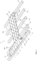
- the modular conveyor chain 6 and the modules 1 can be seen in more detail in Figs. 2 and 3 .
- the injection molded plastic chain module 1 which is for a modular conveyor chain 6, comprises a substantially elongate conveying body 2 defining a supporting surface 20 for supporting products to be transported on said conveying body 2.
- the module 1 also comprises a hinge structure 3 for hingedly connecting the plastic chain module 1 with other chain modules 1.
- Said hinge structure 3 is located at a lower side 10 of the plastic chain module 1, and may preferably extend downwardly from the conveying body 2.
- the hinge structure 3 may extend downwards beyond the bottom sides of the wing shaped portions 21, 22.
- the hinge structure 3 may extend downwards beyond the bottom side(s) of one or more supporting wall portion(s) 4 that is/are part of the respective wing shaped portion(s) 21, 22.
- the supporting wall portion(s) 4 may thus extend less far downwards from a top side of the chain module than the hinge structure 3 is extending downwards.
- Outer side surfaces 39 of a downwardly extending hinge structure may for instance form guiding surfaces 39 to be guided by, e.g. side surfaces of, track or guide means 7 for supporting and/or guiding the conveyor chain 6 during use.
- the hinge structure 3 comprises a first hinge structure portion 30, preferably a hinge structure rear portion located at the trailing side 11 of the module 1, which first hinge structure portion 30 defines a first hinge pin receiving space 31 for receiving a hinge pin.
- the hinge structure 3 further comprises a second hinge structure portion 34 and a third hinge structure portion 35.
- said second and third hinge structure portions 34, 35 are formed as hinge structure front portions located at the leading side 12 of the module 1.
- Said second and third hinge structure portions 34, 35 define a second hinge pin receiving space 32 and a third hinge pin receiving space 33, respectively.
- said second and third hinge structure portions 34, 35 are interspaced, e.g.
- first hinge structure portion 30 in the width direction of the module 1, to receive a first hinge structure portion 30, especially a hinge structure rear portion, of a consecutive chain module 1 there between. This may be done in such manner that the second hinge pin receiving space 32, the first hinge pin receiving space 31, and the third hinge pin receiving space 33 are substantially aligned to jointly receive a first hinge pin 100.
- the width of the module 1 can be relatively small, for instance said width not being more than five, more than four, more than three or more than two times larger than the length of the module measured in the conveying direction and/or than the height of the module.
- the width of the hinge structure 3 can be relatively small with respect to width of the module 1, for instance such that the total width of the module 1 is at least 50%, at least 60%, at least 80%, or even at least 100% larger than the width of the hinge structure 3.
- the hinge structure 3 of the module 1 can be arranged such that when two of such modules 1 are interconnected, only a single first hinge structure portion 30 of a first module 1 is located between two interspaced hinge structure portions 34, 35 of a successive module 1. Then no additional first hinge structure portion of the first module 1 is located at a laterally outwardly facing side of the second hinge structure portion 34 of the further module and also no additional first hinge structure portion of the first module is then located at a laterally outwardly facing side of the third hinge structure portion 35.
- the module may comprise a single first hinge structure portion 30 (and may then thus be free of any further first hinge structure portions).
- the module 1 may comprise a single second hinge structure portion 34 (and no further second hinge structure portions) and a single third hinge structure portion 35 (and no further third hinge structure portions).
- the substantially elongate conveying body 2 of the chain module 1 comprises a central portion 23, which, seen in a widthwise direction of the module 1, may substantially extend from the second hinge structure portion 34 to the third hinge structure portion 35. Further, the substantially elongate conveying body further 2 comprises two wing shaped portions 21, 22 that substantially extend away from said central portion 23 in a respective lateral direction LD21, LD22.
- Bottom sides 24, 25 of said wing shaped portions 21, 22 are arranged to be supported by a guide track 7, for instance by a top surface 70 or a so-called guide surface 70, especially a substantially horizontally oriented top surface 70, of said guide track 7 and/or of one or more respective ones of multiple elongated guides 71 of said guide track 7.
- Each of both wing shaped portions 21, 22 comprises a respective top plate portion 26, 27 defining a part of the supporting surface 20 for supporting products to be transported. It is noted that the central portion 23 may additionally also form a part of the supporting surface 20. Preferably, the supporting surface 20 and or the top plate portions 26, 27 may be substantially planar.
- each of said top plate portions 26, 27 has a thickness T26, T27, which can be measured in a direction substantially transverse to the conveying direction 65 and substantially transverse to the width direction of the chain module 1, being less than 1/3 of the total thickness T21, T22 of the respective wing shaped portion 21, 22, which also can be measured in a direction substantially transverse to the conveying direction 65 and substantially transverse to the width direction of the chain module 1.
- the thickness of the thickness T26, T27 of the top plate portion 26, 27 can be less than 25%, less than 20%, or even less than 15% or less than 10%, of the total thickness T21, T22 of the wing shaped portion 21, 22.
- the thickness or so-called height T21, T22 of the wing shaped portion can be between 3 mm and 40 mm, preferably in a range from 4 mm to 35 mm, such as for instance a height of about 4 mm, about 8.7 mm, or about 12.7 mm
- the thickness T26, T27 of the top plate portion 26, 27 can for instance be between 0.5 and 4 mm, preferably between 1.5 mm and 2.5 mm, such as for instance about 1.5, 1.8, or 2.0 mm.
- each wing shaped portion 21, 22 further comprises one or more supporting wall portions 4 for supporting the respective top plate portion 26, 27, wherein the supporting wall portions 4 extend substantially downwards D4 from the respective top plate portion 26, 27. It is noted that although the supporting wall portions 4 may extend substantially transversely to the top plate portion 26, 27, said supporting wall portions 4 may alternatively extend in another direction. For example, they can be slanted to some extent.
- top plate portion 26, 27, especially a rear end thereof, may extend beyond the supporting walls portions 4 supporting it. This can for instance be seen in Figs. 4 and 5 .
- the top plate portion may thus overhang the walls portions 4, for instance in order to provide space 21S for accommodating a front portion 21F, preferably a rounded off front portion 21F, of a wing shaped portion 21, 22 of an adjacent chain module 1 at least partly.
- the central portion 23 of the substantially elongate conveying body 2 may comprise a top plate portion 28 defining a part of the supporting surface 20 for supporting products to be transported.
- the top plate portions 26, 27, 28 can have substantially the same thickness T26, T27, T28.
- lower ends 40 of at least a part of the one or more supporting wall portions 4 of each wing shaped portion 21, 22 form bottom surfaces to be guided by a guide track 7, especially multiple, e.g. two, elongated guides 71 of the guide track 7, in particular by a top surface 70 or a so-called guide surface 70, especially a substantially horizontally oriented top surface 70, of said a respective one of said elongated guides of a guide track.
- a guide track 7 especially multiple, e.g. two, elongated guides 71 of the guide track 7, in particular by a top surface 70 or a so-called guide surface 70, especially a substantially horizontally oriented top surface 70, of said a respective one of said elongated guides of a guide track.
- bottom sides 24, 25 of the wing shaped portions 21, 22 can be formed by at least a part of the one or more supporting wall portions 4.
- Contact areas of the bottom side 24, 25 of the wing shaped portions 21, 22, for contact with a top surface 70 of a guide track 7, can for instance be formed by a line pattern, e.g. a line pattern of which the lines all substantially have the same width or thickness.
- the line pattern may comprise a comb pattern resembling a comb, may comprise multiple substantially parallel lines, may comprise lines with free outer ends, and/or may comprise maze shaped sections.
- the supporting walls may for instance be formed as ribs or walls that are branched off into multiple interconnected ribs or walls.
- bottom surfaces of the wing shaped portions 21, 22 to be guided by a guide track 7 can be formed at least partly by a bottom surface of a bottom plate (not shown), which for instance may be interspaced from the top plate 26, 27 and can preferably be substantially parallel with said top plate.
- supporting wall portions 4 can be formed between the bottom plate and the top plate 26, 27 by means of one or more slides of the mold used to injection mold the chain module 1. It is noted that, also in alternative embodiments, the top plate 26, 27 and/or the supporting surface 20 may be substantially parallel with the bottom surface of the wing shaped portions 21, 22 to be supported by the guide track 7.
- the supporting wall portions 4 can comprise front wall sections 41a, 41b extending substantially downwards from leading edges 26a, 27a of the top plate portions 26, 27. This may for instance counteract that dirt or debris can accumulate in open spaces 45a, 45b in the wing shaped portions.
- the leading edges 26a, 27a of two respective top plate portions 26, 27 may be substantially straight and may be substantially in line with each other.
- Each of two front wall sections 41a, 41b extending substantially downwards from a respective one of the two leading edges 26a, 27a may preferably be substantially straight as well, and said two front wall sections 41a, 41b may be substantially in line with each other.
- the supporting wall portions 4 may comprise side wall sections 42a, 42b extending downwards from lateral outer edges 26b, 27b of the top plate portions 26, 27. Also this may for instance counteract that dirt or debris can accumulate in open spaces 45a, 45b in the wing shaped portions 21, 22.
- the supporting wall portions 4 of a respective wing shaped portion 21, 22 can comprise wall portions 42a, 43; 41a, 44 that are interspaced with respect to each other, and which preferably may extend substantially parallel to each other.
- they are interspaced in such manner that the width W45a; W45b of an interspace 45a; 45b between two adjacent wall portions 42a, 43; 41b, 44, preferably substantially parallel wall portions 42a, 43; 41b, 44, is wider than the thickness T4: T42a, T43; T41b, T44 of each of said two wall portions 42a, 43; 41b, 44.
- the width W45a, W45b of the interspace 45a, 45b can be at least 120%, preferably at least 150%, more preferably at least 200%, of the thickness of the thickest of said two adjacent wall portions, which two wall portions preferably can have substantially equal thicknesses.
- One or more empty spaces 45a, 45b and/or interspaces 45a, 45b, and preferably all, may be substantially elongated and/or may be substantially have a corridor like shape.
- the wing shape portions 21, 22 may be formed as substantially hollow wing shaped portions. This is, for instance more than 50%, preferably more than 60%, such as for instance at least 70%, of the total volume of the wing shaped portion may be formed by one or more empty spaces, whereas less than 50%, preferably less than 40%, such as for instance at most 30%, of the total volume of the wing shaped portion is formed by plastic material.
- the second hinge pin receiving space 32 and the third hinge pin receiving space 33 can be defined by a relatively thin cylindrically shaped wall 320, 330.
- the term "relatively thin" in the context of said relatively thin cylindrically shaped wall 320, 330 may, at least in embodiments, be understood as meaning that said cylindrically shaped wall 320, 330 has a wall thickness T320, T330 that is relatively thin with respect to the outer diameter of said cylinder.
- said wall thickness T320, T330 may be at most 20% of the outer diameter of said cylinder, preferably no more than 15% of said outer diameter, or even no more than 10% of said outer diameter.
- "relatively thin” in the context of said relatively thin cylindrically shaped wall 320, 330 may, at least in embodiments, be understood as meaning that said cylindrically shaped wall 320, 330 has a wall thickness T320, T330 that is relatively thin with respect to the total height of the hinge structure 3, and/or with respect to the total height of the second hinge structure portion 34 and/or the third hinge structure portion 35, which may be measured from a top side of the module and/or the supporting surface 20 of the module to the bottom end of the hinge structure 3 and/or the bottom end of the respective hinge structure portion 34, 35.
- the outer diameter of the respective cylinder may be understood as the cross-sectional height and/or the cross-sectional width of the cylinder and/or as the largest one thereof.
- Said relatively thin cylindrically walls 320, 330 defining the second hinge pin receiving space 32 and the third hinge pin receiving space 33 can preferably have a thickness T320, T330 substantially equal to the thickness T26, T27 of the top plate portions 26, 27 and/or substantially equal to the thickness T4; T42a, T43; T41a, T44 of the supporting wall portions 4.
- said relatively thin cylindrically shaped walls 320, 330 preferably have a length, e.g. seen in their axial direction and/or in the width direction of the module 1, which length is larger than the thickness T330 of the relatively thin cylindrically shaped walls 320, 330.
- each of the two relatively thin cylindrically shaped walls 320, 330 may be provided with at least one flange 321, 322; 331, 332, preferably at least a flange 321, 331 located at an outermost end 323, 333 of the cylindrically shaped wall 320, 330.
- Said one or more flanges may preferably extend substantially transverse to the axial direction of the cylindrically shaped walls 320, 330 and/or substantially in a vertical plane extending in the conveying direction.
- the flange or flanges 321, 322; 331, 332 provided at the two relatively thin cylindrically shaped walls 320, 330 can have a thickness T332, T331 substantially equal to the thicknesses T330 of the relatively thin cylindrically shaped walls 320, 330, substantially equal to the thickness T26, T27 of the top plate portions 26, 27 and/or substantially equal to the thickness T4; T42a, T43; T41a, T44 of the supporting wall portions 4.
- Wall portions 3321 defining lateral side surfaces 39 of the hinge structure 3 can for instance be formed by wall portions at least partly formed by outer flanges 321, 331 located at outer ends of the relatively thin cylindrically shaped walls 320, 330 and/or by wall portions formed by the second and third hinge structure portions 34, 35.
- wall portions 321 defining lateral side surfaces 39 of the hinge structure 3 can extend in a substantially vertical plane, preferably substantially in the conveying direction of the module 1.
- such wall portions 3321 may then during use form guiding surfaces to be guided along a guide track, e.g. along side surfaces of elongated guides 71 of said guide track 7 and/or along side surfaces of an elongated slot in said guide track 7. This may for instance prevent undesired lateral movement of the modules 1 and/or the chain 6.
- said preferably substantially vertically extending wall portions 3321 may turn off in an inward direction and then turn off back into a direction substantially parallel with the conveyor direction such that a first section 3321c of the wall portion 3321 located near the first hinge pin receiving space 31 is substantially parallel to a second section 3321a of said wall portion 3321 located near the second or third hinge pin receiving space 32, 33.
- An intermediate section 3321b of the wall portion 3321 located between the first and second sections 3321c, 3321a may be extending substantially vertical and may be curved and/or slanted with respect to said first and second sections 3321c, 3321a.
- the first hinge pin receiving space 31 is at least partly defined by a relatively thin wall 310, said wall 310 being formed by at least part of a cylinder.
- said relatively thin wall 310 which is formed by at least part of a cylinder, has a wall thickness T310 that is relatively thin with respect to the outer diameter of said cylinder, said wall thickness T310 being 10% outer diameter of said cylinder
- relatively thin wall 310 in the context of said relatively thin wall 310 may, at least in embodiments, be understood as meaning that said wall 310 has a wall thickness T310 that is relatively thin with respect to the total height of the hinge structure 3, and/or with respect to the total height of the first hinge structure portion 31, which may be measured from a top side of the module 1 and/or the supporting surface 20 of the module 1 to the bottom end of the hinge structure 3 and/or the bottom end of said first hinge structure portion 31.
- Said cylinder is formed as a round cylinder, or as an oval cylinder (see e.g. the embodiment shown in Fig. 4 ), wherein the outer diameter of the cylinder is to be understood as the cross-sectional height or the cross-sectional width of the cylinder as the largest one thereof, in particular the cross-sectional width, which may be measured in the conveying direction 65.
- said relatively thin wall 310 at least partly defining the first hinge pin receiving space 31 can have a thickness T310 substantially equal to the thicknesses T320, T330 of the relatively thin cylindrically shaped walls 320, 330 defining the second and third hinge pin receiving spaces 32, 33, substantially equal to the thicknesses T331; T332 of the flange or flanges 321, 322; 331, 332 provided at the two relatively thin cylindrically shaped walls 320, 330, substantially equal to the thickness T26, T27 of the top plate portions 26, 27 and/or substantially equal to the thickness T4; T42a, T43; T41a, T44 of the supporting wall portions 4.
- the relatively thin wall 310 at least partly defining the first hinge pin receiving space 31 is provided with at least one or more flanges 311, 311a, and/or rib or wall portions 311, 311a, which may extend substantially transverse with respect to the longitudinal direction of the first hinge pin receiving space 31 and/or with respect to the width direction of the module 1.
- the flange or flanges 311 provided at the relatively thin wall 310 at least partly defining the first hinge pin receiving space 31 may preferably have a thickness T311a substantially equal to the thickness T310 of said relatively thin wall 310, substantially equal to the thickness T330 of the relatively thin cylindrically shaped wall 320, 330 defining the second and third hinge pin receiving spaces 32, 33, substantially equal to the thicknesses T331 of the flange or flanges 321, 322; 331, 332 provided at the two relatively thin cylindrically shaped walls 320, 330, substantially equal to the thickness T26, T27 of the top plate portions 26, 27 and/or substantially equal to the thickness T4; T42a, T43; T41a, T44 of the supporting wall portions 4.
- the first section 3321c of the wall portion 3321 located near the first hinge pin receiving space 31 can be formed by an outer flange 321 on the relatively thin wall 310 defining the first hinge pin receiving space 31.
- first wall 310 defining the first hinge pin receiving space 31 may be interconnected to the second and/or third relatively thin cylindrically shaped wall 320, 330 by more than one respective wall portion 3321.
- a second, preferably substantially vertical wall or wall portion 3322 may be provided, which can be interspaced from said first wall portion 3321, especially in a substantially parallel manner.
- An inner space 38 between said interspaced wall portions 3322, 3321 may be defined by said wall portions and by an undersurface of a top plate portion 28a and outer surfaces of the respective hinge pin defining walls 310, 320, 330.
- slots 29 can be provided in the top plate 26, 27, 28, 28a.
- the slots 29 can counteract accumulation of plastic material, e.g. when parts of the hinge structure 3 interconnecting a hinge pin receiving part at a front side of the module with a hinge pin receiving part at a rear side of the module have a width substantially larger than a wall thickness of the module.
- Said slots 29 can for instance for interspaces between ribs and/or flanges 321, 322; 311a, 311c provided on a respective relatively thin wall 310, 320, 330 defining a hinge pin receiving space.
- the wing shaped portion, or even the complete injection molded plastic chain module 1 can substantially consist of a plurality of relatively thin plate and/or wall portions 26, 27, 28, 4, 41, 42, 43, 44, 310, 311, 320, 321, 322, 330, 331, 332.
- all of said relatively thin wall or plate portions can all have a thickness T26, T27, T4, T42, T42a, T43, T331, T332 between 0.5 and 4 mm, preferably between 1.5 mm and 2.5 mm, such as for instance about 1.5, 1.8, 2.0, or 2.5 mm.
- the wing shaped portion 21, 22, or another part of the module 1 such as for instance the hinge structure 3, comprises one or more thickenings 430, such as for instance is the case in the exemplary embodiment shown in Fig. 6
- the wing shaped portion 21, 22, and preferably the whole module 1 may still be considered as substantially consisting of a plurality of relatively thin plate and/or wall portions, especially in embodiments in which the thickening 430 can be considered as an intersection of two intersecting plate and/or wall portions.
- the thickening 430 can be considered as an intersection of two intersecting plate and/or wall portions.
- the thickening 430 can be considered as an intersection at which a first plate and/or wall portion 43 intersects with a substantially transverse plate and/or wall portion, wherein said transverse plate and/or wall portion is relatively short and has rounded off distal ends, as a result of which said intersecting plate and/or wall portions can substantially resemble a thickening 430 and/or a post like structure 430.
- such the thickness or diameter of such thickening 430 and/or a post like structure 430 should not substantially exceed the thickness or diameter of other intersections 60 between intersecting plate and/or wall portions 311, 310.
- all relatively thin wall or plate portions can preferably have a substantially equal thickness.
- “having substantially the same thickness” and/or “having a substantially equal thickness” may at least be considered as meaning that the thickness of the plate and/or wall portions differ from each other to such a small extent that the thickness of the thickest plate or wall portion is at most 250%, preferably at most 200% or at most 150%, more preferably less than 120%, even more preferably less than 115%, such as for instance at most 110% or 105%, of the thickness of the thinnest plate and/or wall portion.
- one or more plate or wall portions can be rounded off and/or tapered such as for instance can be seen in Fig.
- the thickness of a plate and/or wall portion 27, 43 should not be measured at a narrowed section 27x, 43x, e.g. a tapered end section 27x, 43x of said plate and/or wall portion 27, 43.
- the tapered end section 27x of the top plate portion 27 of the wing shaped portions 21 should be disregarded when determining the thickness T27 of said top plate portion 27.
- local thickenings 60, 430 especially when they can be considered as intersections between plate and/or wall portions, should also be disregarded when determining the thickness of a respective plate and/or wall portion 40, 310, 311.
- “having substantially the same thickness” and/or “having a substantially equal thickness” may be considered as meaning that the diameter of the largest virtual sphere that can be completely enclosed within the plastic material forming the chain module 1 can be at most 300%, preferably at most 250%, more preferably at most 220%, such as for instance about 200%, of the diameter of the largest virtual sphere that can be enclosed within the plastic material at the thinnest wall portion section that is not tapered.
- the largest virtual sphere or spheres that at a certain position can be completely enclosed within the tapered end sections 27x, 43x of plate and/or wall portions 27, 43 of the module 1 should then thus be disregarded for determining the diameter of the largest virtual sphere that can be enclosed within the plastic material at the thinnest wall portion section of the chain module 1.
Landscapes
- Engineering & Computer Science (AREA)
- Mechanical Engineering (AREA)
- Chain Conveyers (AREA)
Claims (13)
- Spritzgegossenes Kunststoffkettenmodul (1) für eine modulare Förderkette (6), umfassend einen im Wesentlichen länglichen Förderkörper (2), der eine Tragfläche (20) zum Tragen von auf dem Förderkörper (2) zu transportierenden Produkten definiert, und eine Scharnierstruktur (3) zum gelenkigen Verbinden des Kunststoffkettenmoduls (1) mit anderen Modulen (1), wobei die Scharnierstruktur (3) an einer Unterseite (10) des Kunststoffkettenmoduls (1) angeordnet ist, wobei die Scharnierstruktur (3) einen ersten Scharnierstrukturabschnitt (30) umfasst, vorzugsweise einen hinteren Scharnierstrukturabschnitt (30), der an der hinteren Seite (11) des Moduls (1) angeordnet ist, wobei der erste Scharnierstrukturabschnitt (30) einen ersten Scharnierstiftaufnahmeraum (31) zum Aufnehmen eines Scharnierstifts (100) definiert, wobei die Scharnierstruktur (3) ferner einen zweiten Scharnierstrukturabschnitt (34) und einen dritten Scharnierstrukturabschnitt (35) umfasst, vorzugsweise zwei vordere Scharnierstrukturabschnitte (34, 35), die an der vorderen Seite (12) des Moduls (1) angeordnet sind, wobei der zweite und der dritte Scharnierstrukturabschnitt (34, 35) einen zweiten Scharnierstiftaufnahmeraum (32) bzw. einen dritten Scharnierstiftaufnahmeraum (33) definieren, wobei der zweite und der dritte Scharnierstrukturabschnitt (34, 35) voneinander beabstandet sind, um einen ersten Scharnierstrukturabschnitt (30), vorzugsweise einen hinteren Scharnierstrukturabschnitt (30), eines aufeinanderfolgenden Kettenmoduls (1) dazwischen aufzunehmen, wobei der im Wesentlichen längliche Förderkörper (2) einen zentralen Abschnitt (23) umfasst, wobei der im Wesentlichen längliche Förderkörper (2) ferner zwei flügelförmige Abschnitte (21, 22) umfasst, die sich im Wesentlichen von dem zentralen Abschnitt (23) in einer jeweiligen seitlichen Richtung (LD21, LD22) weg erstrecken, wobei die Unterseiten (24, 25) der flügelförmigen Abschnitte (21, 22) angeordnet sind, um von einer Führungsschiene (7) getragen zu werden, wobei jeder der beiden flügelförmigen Abschnitte (21, 22) einen jeweiligen oberen Plattenabschnitt (26, 27) umfasst, der einen Teil der Tragfläche (20) zum Tragen von zu transportierenden Produkten definiert, wobei jeder der oberen Plattenabschnitte (26, 27) eine Dicke (T26, T27) aufweist, die weniger als 1/3 der Dicke (T21, T22) des jeweiligen flügelförmigen Abschnitts (21, 22) beträgt, und wobei jeder flügelförmige Abschnitt (21, 22) ferner einen oder mehrere Stützwandabschnitte (4) zum Stützen des jeweiligen oberen Plattenabschnitts (26, 27) umfasst, wobei sich die Stützwandabschnitte (4) von dem jeweiligen oberen Plattenabschnitt (26, 27) im Wesentlichen nach unten (D4) erstrecken, dadurch gekennzeichnet,dass der erste Scharnierstiftaufnahmeraum (31) zumindest teilweise durch eine relativ dünne Wand (310) definiert ist, die durch zumindest einen Teil eines Zylinders, wie beispielsweise einen runden Zylinder oder einen ovalen Zylinder, gebildet ist, wobei die relativ dünne Wand (310) eine Wanddicke (T310) aufweist, die höchstens 10 % des Außendurchmessers des Zylinders beträgt, wobei der Außendurchmesser des Zylinders als die Querschnittshöhe oder die Querschnittsbreite des Zylinders oder als die größte davon zu verstehen ist, unddass die relativ dünne Wand (310), die durch zumindest einen Teil des Zylinders gebildet ist, mit Flanschen (311, 311a, 311b, 311, c) und/oder Rippen- oder Wandabschnitten (311, 311a, 311b, 311c) bereitgestellt ist.
- Spritzgegossenes Kunststoffkettenmodul (1) nach Anspruch 1, wobei untere Enden (40) von zumindest einem Teil des einen oder der mehreren Stützwandabschnitte (4) jedes flügelförmigen Abschnitts (21, 22) Bodenflächen bilden, die durch eine Führungsschiene (7), vorzugsweise durch entsprechende längliche Führungen (710) einer Führungsschiene (7), geführt werden.
- Spritzgegossenes Kunststoffkettenmodul (1) nach Anspruch 1 oder 2, wobei die Stützwandabschnitte (4) Vorderwandabschnitte (41a, 41b) umfassen, die sich von Vorderkanten (26a, 27a) der oberen Plattenabschnitte (26, 27) im Wesentlichen nach unten erstrecken.
- Spritzgegossenes Kunststoffkettenmodul (1) nach einem der vorstehenden Ansprüche, wobei die Stützwandabschnitte (4) Seitenwandabschnitte (42a, 42b) umfassen, die sich von seitlichen Außenkanten (26b, 27b) der oberen Plattenabschnitte (26, 27) nach unten erstrecken.
- Spritzgegossenes Kunststoffkettenmodul (1) nach einem der vorstehenden Ansprüche, wobei die Stützwandabschnitte (4) eines jeweiligen flügelförmigen Abschnitts (21, 22) mehrere Wandabschnitte (42a, 43, 41a, 44), vorzugsweise im Wesentlichen parallele Wandabschnitte (42a, 43, 41a, 44) umfassen, die in Bezug zueinander so beabstandet sind, dass ein Zwischenraum (45a, 45b) zwischen zwei benachbarten Wandabschnitten (42a, 43, 41a, 44) breiter ist als die Dicke (T4, T42a, T43, T41b, T44) jedes der beiden Wandabschnitte (42a, 43, 41a, 44).
- Spritzgegossenes Kunststoffkettenmodul (1) nach einem der vorstehenden Ansprüche, wobei die flügelförmigen Abschnitte (21, 22) als im Wesentlichen hohle flügelförmige Abschnitte (21, 22) gebildet sind.
- Spritzgegossenes Kunststoffkettenmodul (1) nach einem der vorstehenden Ansprüche, wobei der zweite Scharnierstiftaufnahmeraum (32) und der dritte Scharnierstiftaufnahmeraum (33) durch eine relativ dünne, zylindrisch geformte Wand (320, 330) definiert sind.
- Spritzgegossenes Kunststoffkettenmodul (1) nach Anspruch 7, wobei jede der beiden relativ dünnen zylindrisch geformten Wände (320, 330) mit mindestens einem Flansch (321, 322, 331, 332), vorzugsweise mit mindestens einem Flansch (321, 331) bereitgestellt ist, der an einem äußersten Ende (323, 333) der zylindrisch geformten Wand (320, 330) angeordnet ist.
- Spritzgegossenes Kunststoffkettenmodul (1) nach einem der vorstehenden Ansprüche, wobei die Flansche (311, 311a) und/oder Rippen- oder Wandabschnitte (311, 311a), die an der relativ dünnen Wand (310), die zumindest teilweise den ersten Scharnierbolzenaufnahmeraum (31) definiert, bereitgestellt sind, im Wesentlichen quer zu der Längsrichtung des ersten Scharnierbolzenaufnahmeraums (31) und/oder zu der Breitenrichtung des Moduls (1) verlaufen.
- Spritzgegossenes Kunststoffkettenmodul (1) nach einem der vorstehenden Ansprüche, wobei das Modul (1) im Wesentlichen aus einer Vielzahl von relativ dünnen Platten- und/oder Wandabschnitten (26, 27, 28, 4, 41, 42, 43, 44, 310, 311, 320, 321, 322, 330, 331, 332) besteht, die vorzugsweise alle eine im Wesentlichen gleiche Dicke aufweisen (T26, T27, T4, T42, T42a, T43, T331, T332), z. B. wobei die Dicke des dicksten Platten- oder Wandabschnitts höchstens etwa 250 %, oder höchstens etwa 200 %, vorzugsweise weniger als 150 %, oder weniger als 120 %, der Dicke des dünnsten Platten- oder Wandabschnitts beträgt.
- Modulare Förderkette (6), umfassend eine Vielzahl von spritzgegossenen Kunststoffkettenmodulen (1) nach einem der Ansprüche 1 bis 10.
- Fördersystem (5), umfassend eine modulare Förderkette (6) nach Anspruch 11.
- Fördersystem (5) nach Anspruch 12, ferner umfassend Führungsmittel (7b), z. B. eine Führungsschiene (7), die zwei längliche Führungen (71) umfasst, wobei Unterseiten der flügelförmigen Abschnitte (21, 22) von Modulen (1) einer oberen Bahn der Förderkette (6) während der Verwendung des Fördersystems (5) durch eine jeweilige der beiden länglichen Führungen (71) einer Führungsschiene (7) geführt werden.
Applications Claiming Priority (2)
| Application Number | Priority Date | Filing Date | Title |
|---|---|---|---|
| NL2015697A NL2015697B1 (en) | 2015-10-30 | 2015-10-30 | Conveyor system, modular conveyor chain and injection molded plastic chain module. |
| PCT/NL2016/050753 WO2017074192A1 (en) | 2015-10-30 | 2016-10-28 | Conveyor system, modular conveyor chain and injection molded plastic chain module |
Publications (3)
| Publication Number | Publication Date |
|---|---|
| EP3368450A1 EP3368450A1 (de) | 2018-09-05 |
| EP3368450C0 EP3368450C0 (de) | 2024-10-16 |
| EP3368450B1 true EP3368450B1 (de) | 2024-10-16 |
Family
ID=55697420
Family Applications (1)
| Application Number | Title | Priority Date | Filing Date |
|---|---|---|---|
| EP16801863.8A Active EP3368450B1 (de) | 2015-10-30 | 2016-10-28 | Fördersystem, modulare förderkette und spritzgegossenes kunststoffkettemodul |
Country Status (5)
| Country | Link |
|---|---|
| US (1) | US10384875B2 (de) |
| EP (1) | EP3368450B1 (de) |
| CN (1) | CN108473256B (de) |
| NL (1) | NL2015697B1 (de) |
| WO (1) | WO2017074192A1 (de) |
Families Citing this family (6)
| Publication number | Priority date | Publication date | Assignee | Title |
|---|---|---|---|---|
| US12595131B2 (en) * | 2020-09-18 | 2026-04-07 | Gram Equipment A/S | Chain construction |
| DE102023204178A1 (de) * | 2023-05-05 | 2024-11-07 | Robert Bosch Gesellschaft mit beschränkter Haftung | Kettenglied für eine kurvengängige Förderkette, kurvengängige Förderkette und Transfersystem mit kurvengängiger Förderkette |
| USD1104399S1 (en) * | 2023-07-21 | 2025-12-02 | Movex S.P.A. | Conveyor module |
| USD1103545S1 (en) * | 2023-07-21 | 2025-11-25 | Movex S.P.A. | Conveyor module |
| USD1103546S1 (en) * | 2023-07-21 | 2025-11-25 | Movex S.P.A. | Conveyor module |
| USD1107369S1 (en) * | 2023-07-21 | 2025-12-23 | Movex S.P.A. | Conveyor module |
Citations (2)
| Publication number | Priority date | Publication date | Assignee | Title |
|---|---|---|---|---|
| GB2231318A (en) * | 1989-04-14 | 1990-11-14 | Protech Engineering Ltd | Conveyor belting |
| WO2007073161A1 (en) * | 2005-12-19 | 2007-06-28 | Rexnord Flattop Europe B.V. | Module for a conveyor mat, modular conveyor mat and conveyor |
Family Cites Families (8)
| Publication number | Priority date | Publication date | Assignee | Title |
|---|---|---|---|---|
| US4729469A (en) * | 1985-11-15 | 1988-03-08 | Lapeyre James M | Flat top conveyor belt |
| US4880107A (en) * | 1987-07-31 | 1989-11-14 | Rexnord Corporation | Table top chain link with rib |
| NL9201999A (nl) * | 1992-11-16 | 1994-06-16 | Mcc Nederland | Uit kunststof modules opgebouwde transportmat en modules voor een dergelijke transportmat. |
| USD486289S1 (en) * | 2000-07-05 | 2004-02-03 | Flexlink Components Ab | Link for a conveyor |
| JP4010755B2 (ja) * | 2000-08-31 | 2007-11-21 | 株式会社椿本チエイン | コンベヤチェーン |
| NL1022132C2 (nl) * | 2002-12-10 | 2004-06-11 | Mcc Nederland | Kettingmodule en modulaire kettingtransporteur. |
| ITTV20050120A1 (it) * | 2005-08-12 | 2007-02-13 | Plastomeccanica Spa | Maglia di catena trasportatrice |
| US7367448B2 (en) * | 2006-07-20 | 2008-05-06 | Habasit Ag | Chain with undulated edge |
-
2015
- 2015-10-30 NL NL2015697A patent/NL2015697B1/en active
-
2016
- 2016-10-28 WO PCT/NL2016/050753 patent/WO2017074192A1/en not_active Ceased
- 2016-10-28 EP EP16801863.8A patent/EP3368450B1/de active Active
- 2016-10-28 US US15/772,209 patent/US10384875B2/en active Active
- 2016-10-28 CN CN201680077566.1A patent/CN108473256B/zh active Active
Patent Citations (2)
| Publication number | Priority date | Publication date | Assignee | Title |
|---|---|---|---|---|
| GB2231318A (en) * | 1989-04-14 | 1990-11-14 | Protech Engineering Ltd | Conveyor belting |
| WO2007073161A1 (en) * | 2005-12-19 | 2007-06-28 | Rexnord Flattop Europe B.V. | Module for a conveyor mat, modular conveyor mat and conveyor |
Also Published As
| Publication number | Publication date |
|---|---|
| EP3368450C0 (de) | 2024-10-16 |
| WO2017074192A1 (en) | 2017-05-04 |
| EP3368450A1 (de) | 2018-09-05 |
| CN108473256B (zh) | 2021-04-09 |
| US20180312339A1 (en) | 2018-11-01 |
| US10384875B2 (en) | 2019-08-20 |
| CN108473256A (zh) | 2018-08-31 |
| NL2015697B1 (en) | 2017-05-31 |
Similar Documents
| Publication | Publication Date | Title |
|---|---|---|
| EP3368450B1 (de) | Fördersystem, modulare förderkette und spritzgegossenes kunststoffkettemodul | |
| EP1687221B1 (de) | Kunststoffförderbandmodule mit seitenschutz | |
| US3939964A (en) | Apron or plate belt conveyor | |
| CN101394736B (zh) | 用于对碰撞敏感的产品的输送装置 | |
| US9751694B2 (en) | Side-flexing conveyors | |
| JP6805148B2 (ja) | 成形された底側表面を有するコンベヤベルトモジュール | |
| JPH11240619A (ja) | 無端チェーン型コンベアの運搬セクションから出る際に物品を受け入れるためのプレート用モジュラー型構造体 | |
| US5782340A (en) | Tapered side support for conveyor belts | |
| CA2544531A1 (en) | Modular plastic conveyor belt with high beam strength | |
| US20140027251A1 (en) | Module for a modular conveyor mat and modular conveyor mat | |
| US20090308716A1 (en) | Belt Conveyor | |
| EP1890950B1 (de) | Kunststoffförderbänder und module mit seitenkanälen | |
| EP3572358B1 (de) | Tragstruktur mit verbessertem boden für einen gelenkigen gliederförderer | |
| US7159709B2 (en) | Conveyor belt | |
| US20140008187A1 (en) | Modular conveyor mat and module therefor | |
| US8127957B2 (en) | Suspended receptacle for at least one piece of dough and set consisting of a plurality of suspended receptacles of this type | |
| CN102530296B (zh) | 用于形成卷烟组的装置 | |
| CN115348939B (zh) | 模块化输送机垫及其模块 | |
| WO2016095933A1 (en) | Modular belt link | |
| CN113795441A (zh) | 具有交替的驱动表面的模块化传送带 | |
| KR100975879B1 (ko) | 금속 폐기물 컨베이어용 링크판 | |
| NL9100847A (nl) | Transportinrichting. | |
| EP2240392A1 (de) | Rückführungs-biegungssegment |
Legal Events
| Date | Code | Title | Description |
|---|---|---|---|
| STAA | Information on the status of an ep patent application or granted ep patent |
Free format text: STATUS: UNKNOWN |
|
| STAA | Information on the status of an ep patent application or granted ep patent |
Free format text: STATUS: THE INTERNATIONAL PUBLICATION HAS BEEN MADE |
|
| PUAI | Public reference made under article 153(3) epc to a published international application that has entered the european phase |
Free format text: ORIGINAL CODE: 0009012 |
|
| STAA | Information on the status of an ep patent application or granted ep patent |
Free format text: STATUS: REQUEST FOR EXAMINATION WAS MADE |
|
| 17P | Request for examination filed |
Effective date: 20180524 |
|
| AK | Designated contracting states |
Kind code of ref document: A1 Designated state(s): AL AT BE BG CH CY CZ DE DK EE ES FI FR GB GR HR HU IE IS IT LI LT LU LV MC MK MT NL NO PL PT RO RS SE SI SK SM TR |
|
| AX | Request for extension of the european patent |
Extension state: BA ME |
|
| DAV | Request for validation of the european patent (deleted) | ||
| DAX | Request for extension of the european patent (deleted) | ||
| STAA | Information on the status of an ep patent application or granted ep patent |
Free format text: STATUS: EXAMINATION IS IN PROGRESS |
|
| 17Q | First examination report despatched |
Effective date: 20210618 |
|
| P01 | Opt-out of the competence of the unified patent court (upc) registered |
Effective date: 20230522 |
|
| GRAP | Despatch of communication of intention to grant a patent |
Free format text: ORIGINAL CODE: EPIDOSNIGR1 |
|
| STAA | Information on the status of an ep patent application or granted ep patent |
Free format text: STATUS: GRANT OF PATENT IS INTENDED |
|
| INTG | Intention to grant announced |
Effective date: 20240516 |
|
| GRAS | Grant fee paid |
Free format text: ORIGINAL CODE: EPIDOSNIGR3 |
|
| GRAA | (expected) grant |
Free format text: ORIGINAL CODE: 0009210 |
|
| STAA | Information on the status of an ep patent application or granted ep patent |
Free format text: STATUS: THE PATENT HAS BEEN GRANTED |
|
| AK | Designated contracting states |
Kind code of ref document: B1 Designated state(s): AL AT BE BG CH CY CZ DE DK EE ES FI FR GB GR HR HU IE IS IT LI LT LU LV MC MK MT NL NO PL PT RO RS SE SI SK SM TR |
|
| REG | Reference to a national code |
Ref country code: GB Ref legal event code: FG4D |
|
| REG | Reference to a national code |
Ref country code: CH Ref legal event code: EP Ref country code: DE Ref legal event code: R096 Ref document number: 602016089868 Country of ref document: DE |
|
| REG | Reference to a national code |
Ref country code: IE Ref legal event code: FG4D |
|
| U01 | Request for unitary effect filed |
Effective date: 20241114 |
|
| P04 | Withdrawal of opt-out of the competence of the unified patent court (upc) registered |
Free format text: CASE NUMBER: APP_61698/2024 Effective date: 20241118 |
|
| U07 | Unitary effect registered |
Designated state(s): AT BE BG DE DK EE FI FR IT LT LU LV MT NL PT RO SE SI Effective date: 20241121 |
|
| U20 | Renewal fee for the european patent with unitary effect paid |
Year of fee payment: 9 Effective date: 20241119 |
|
| PG25 | Lapsed in a contracting state [announced via postgrant information from national office to epo] |
Ref country code: HR Free format text: LAPSE BECAUSE OF FAILURE TO SUBMIT A TRANSLATION OF THE DESCRIPTION OR TO PAY THE FEE WITHIN THE PRESCRIBED TIME-LIMIT Effective date: 20241016 Ref country code: IS Free format text: LAPSE BECAUSE OF FAILURE TO SUBMIT A TRANSLATION OF THE DESCRIPTION OR TO PAY THE FEE WITHIN THE PRESCRIBED TIME-LIMIT Effective date: 20250216 |
|
| PG25 | Lapsed in a contracting state [announced via postgrant information from national office to epo] |
Ref country code: ES Free format text: LAPSE BECAUSE OF FAILURE TO SUBMIT A TRANSLATION OF THE DESCRIPTION OR TO PAY THE FEE WITHIN THE PRESCRIBED TIME-LIMIT Effective date: 20241016 |
|
| PG25 | Lapsed in a contracting state [announced via postgrant information from national office to epo] |
Ref country code: NO Free format text: LAPSE BECAUSE OF FAILURE TO SUBMIT A TRANSLATION OF THE DESCRIPTION OR TO PAY THE FEE WITHIN THE PRESCRIBED TIME-LIMIT Effective date: 20250116 |
|
| PG25 | Lapsed in a contracting state [announced via postgrant information from national office to epo] |
Ref country code: GR Free format text: LAPSE BECAUSE OF FAILURE TO SUBMIT A TRANSLATION OF THE DESCRIPTION OR TO PAY THE FEE WITHIN THE PRESCRIBED TIME-LIMIT Effective date: 20250117 |
|
| PG25 | Lapsed in a contracting state [announced via postgrant information from national office to epo] |
Ref country code: PL Free format text: LAPSE BECAUSE OF FAILURE TO SUBMIT A TRANSLATION OF THE DESCRIPTION OR TO PAY THE FEE WITHIN THE PRESCRIBED TIME-LIMIT Effective date: 20241016 |
|
| PG25 | Lapsed in a contracting state [announced via postgrant information from national office to epo] |
Ref country code: RS Free format text: LAPSE BECAUSE OF FAILURE TO SUBMIT A TRANSLATION OF THE DESCRIPTION OR TO PAY THE FEE WITHIN THE PRESCRIBED TIME-LIMIT Effective date: 20250116 |
|
| REG | Reference to a national code |
Ref country code: CH Ref legal event code: PL |
|
| PG25 | Lapsed in a contracting state [announced via postgrant information from national office to epo] |
Ref country code: SM Free format text: LAPSE BECAUSE OF FAILURE TO SUBMIT A TRANSLATION OF THE DESCRIPTION OR TO PAY THE FEE WITHIN THE PRESCRIBED TIME-LIMIT Effective date: 20241016 |
|
| PG25 | Lapsed in a contracting state [announced via postgrant information from national office to epo] |
Ref country code: MC Free format text: LAPSE BECAUSE OF FAILURE TO SUBMIT A TRANSLATION OF THE DESCRIPTION OR TO PAY THE FEE WITHIN THE PRESCRIBED TIME-LIMIT Effective date: 20241016 |
|
| PG25 | Lapsed in a contracting state [announced via postgrant information from national office to epo] |
Ref country code: CH Free format text: LAPSE BECAUSE OF NON-PAYMENT OF DUE FEES Effective date: 20241031 |
|
| PG25 | Lapsed in a contracting state [announced via postgrant information from national office to epo] |
Ref country code: SK Free format text: LAPSE BECAUSE OF FAILURE TO SUBMIT A TRANSLATION OF THE DESCRIPTION OR TO PAY THE FEE WITHIN THE PRESCRIBED TIME-LIMIT Effective date: 20241016 |
|
| PG25 | Lapsed in a contracting state [announced via postgrant information from national office to epo] |
Ref country code: CZ Free format text: LAPSE BECAUSE OF FAILURE TO SUBMIT A TRANSLATION OF THE DESCRIPTION OR TO PAY THE FEE WITHIN THE PRESCRIBED TIME-LIMIT Effective date: 20241016 |
|
| PLBE | No opposition filed within time limit |
Free format text: ORIGINAL CODE: 0009261 |
|
| STAA | Information on the status of an ep patent application or granted ep patent |
Free format text: STATUS: NO OPPOSITION FILED WITHIN TIME LIMIT |
|
| 26N | No opposition filed |
Effective date: 20250717 |
|
| GBPC | Gb: european patent ceased through non-payment of renewal fee |
Effective date: 20250116 |
|
| PG25 | Lapsed in a contracting state [announced via postgrant information from national office to epo] |
Ref country code: GB Free format text: LAPSE BECAUSE OF NON-PAYMENT OF DUE FEES Effective date: 20250116 |
|
| PG25 | Lapsed in a contracting state [announced via postgrant information from national office to epo] |
Ref country code: IE Free format text: LAPSE BECAUSE OF NON-PAYMENT OF DUE FEES Effective date: 20241028 |
|
| U20 | Renewal fee for the european patent with unitary effect paid |
Year of fee payment: 10 Effective date: 20251028 |
|
| PG25 | Lapsed in a contracting state [announced via postgrant information from national office to epo] |
Ref country code: HU Free format text: LAPSE BECAUSE OF FAILURE TO SUBMIT A TRANSLATION OF THE DESCRIPTION OR TO PAY THE FEE WITHIN THE PRESCRIBED TIME-LIMIT; INVALID AB INITIO Effective date: 20161028 |
|
| PG25 | Lapsed in a contracting state [announced via postgrant information from national office to epo] |
Ref country code: CY Free format text: LAPSE BECAUSE OF FAILURE TO SUBMIT A TRANSLATION OF THE DESCRIPTION OR TO PAY THE FEE WITHIN THE PRESCRIBED TIME-LIMIT; INVALID AB INITIO Effective date: 20161028 |