EP3366972B1 - Haltevorrichtung und ptz-mechanismus eines unbemannten luftfahrzeugs - Google Patents
Haltevorrichtung und ptz-mechanismus eines unbemannten luftfahrzeugs Download PDFInfo
- Publication number
- EP3366972B1 EP3366972B1 EP16897680.1A EP16897680A EP3366972B1 EP 3366972 B1 EP3366972 B1 EP 3366972B1 EP 16897680 A EP16897680 A EP 16897680A EP 3366972 B1 EP3366972 B1 EP 3366972B1
- Authority
- EP
- European Patent Office
- Prior art keywords
- swing rod
- carrier portion
- clamping
- stopping member
- sliding component
- Prior art date
- Legal status (The legal status is an assumption and is not a legal conclusion. Google has not performed a legal analysis and makes no representation as to the accuracy of the status listed.)
- Active
Links
Images


Classifications
-
- F—MECHANICAL ENGINEERING; LIGHTING; HEATING; WEAPONS; BLASTING
- F16—ENGINEERING ELEMENTS AND UNITS; GENERAL MEASURES FOR PRODUCING AND MAINTAINING EFFECTIVE FUNCTIONING OF MACHINES OR INSTALLATIONS; THERMAL INSULATION IN GENERAL
- F16M—FRAMES, CASINGS OR BEDS OF ENGINES, MACHINES OR APPARATUS, NOT SPECIFIC TO ENGINES, MACHINES OR APPARATUS PROVIDED FOR ELSEWHERE; STANDS; SUPPORTS
- F16M11/00—Stands or trestles as supports for apparatus or articles placed thereon ; Stands for scientific apparatus such as gravitational force meters
- F16M11/02—Heads
- F16M11/04—Means for attachment of apparatus; Means allowing adjustment of the apparatus relatively to the stand
- F16M11/041—Allowing quick release of the apparatus
-
- B—PERFORMING OPERATIONS; TRANSPORTING
- B64—AIRCRAFT; AVIATION; COSMONAUTICS
- B64U—UNMANNED AERIAL VEHICLES [UAV]; EQUIPMENT THEREFOR
- B64U20/00—Constructional aspects of UAVs
- B64U20/80—Arrangement of on-board electronics, e.g. avionics systems or wiring
- B64U20/87—Mounting of imaging devices, e.g. mounting of gimbals
-
- F—MECHANICAL ENGINEERING; LIGHTING; HEATING; WEAPONS; BLASTING
- F16—ENGINEERING ELEMENTS AND UNITS; GENERAL MEASURES FOR PRODUCING AND MAINTAINING EFFECTIVE FUNCTIONING OF MACHINES OR INSTALLATIONS; THERMAL INSULATION IN GENERAL
- F16M—FRAMES, CASINGS OR BEDS OF ENGINES, MACHINES OR APPARATUS, NOT SPECIFIC TO ENGINES, MACHINES OR APPARATUS PROVIDED FOR ELSEWHERE; STANDS; SUPPORTS
- F16M13/00—Other supports for positioning apparatus or articles; Means for steadying hand-held apparatus or articles
- F16M13/02—Other supports for positioning apparatus or articles; Means for steadying hand-held apparatus or articles for supporting on, or attaching to, an object, e.g. tree, gate, window-frame, cycle
-
- B—PERFORMING OPERATIONS; TRANSPORTING
- B64—AIRCRAFT; AVIATION; COSMONAUTICS
- B64U—UNMANNED AERIAL VEHICLES [UAV]; EQUIPMENT THEREFOR
- B64U2101/00—UAVs specially adapted for particular uses or applications
- B64U2101/30—UAVs specially adapted for particular uses or applications for imaging, photography or videography
-
- B—PERFORMING OPERATIONS; TRANSPORTING
- B64—AIRCRAFT; AVIATION; COSMONAUTICS
- B64U—UNMANNED AERIAL VEHICLES [UAV]; EQUIPMENT THEREFOR
- B64U2201/00—UAVs characterised by their flight controls
- B64U2201/20—Remote controls
-
- F—MECHANICAL ENGINEERING; LIGHTING; HEATING; WEAPONS; BLASTING
- F16—ENGINEERING ELEMENTS AND UNITS; GENERAL MEASURES FOR PRODUCING AND MAINTAINING EFFECTIVE FUNCTIONING OF MACHINES OR INSTALLATIONS; THERMAL INSULATION IN GENERAL
- F16M—FRAMES, CASINGS OR BEDS OF ENGINES, MACHINES OR APPARATUS, NOT SPECIFIC TO ENGINES, MACHINES OR APPARATUS PROVIDED FOR ELSEWHERE; STANDS; SUPPORTS
- F16M11/00—Stands or trestles as supports for apparatus or articles placed thereon ; Stands for scientific apparatus such as gravitational force meters
- F16M11/02—Heads
- F16M11/04—Means for attachment of apparatus; Means allowing adjustment of the apparatus relatively to the stand
- F16M11/06—Means for attachment of apparatus; Means allowing adjustment of the apparatus relatively to the stand allowing pivoting
-
- F—MECHANICAL ENGINEERING; LIGHTING; HEATING; WEAPONS; BLASTING
- F16—ENGINEERING ELEMENTS AND UNITS; GENERAL MEASURES FOR PRODUCING AND MAINTAINING EFFECTIVE FUNCTIONING OF MACHINES OR INSTALLATIONS; THERMAL INSULATION IN GENERAL
- F16M—FRAMES, CASINGS OR BEDS OF ENGINES, MACHINES OR APPARATUS, NOT SPECIFIC TO ENGINES, MACHINES OR APPARATUS PROVIDED FOR ELSEWHERE; STANDS; SUPPORTS
- F16M2200/00—Details of stands or supports
- F16M2200/02—Locking means
- F16M2200/025—Locking means for translational movement
Definitions
- the present application relates to a fixing apparatus, and in particular, to a clamping apparatus and an unmanned aerial vehicle gimbal.
- US2015028170A1 discloses a clamping apparatus.
- the clamping apparatus comprises a base unit, a movable unit, a carrier unit, a clamping element located on the base unit and two stop elements located on the carrier unit.
- the base unit includes a placement surface for placing an electronic device.
- the movable unit partially extends into the base unit and can move linearly.
- the carrier unit is detachably disposed at the movable unit.
- the clamping element and the two stop elements protrude from two opposite sides of the placement surface so that the electronic device can be clamped and held between the clamping element and two stop elements.
- the movable unit includes:
- clamping unit includes:
- a third stopping member and a fourth stopping member are respectively mounted at two ends of the second swing rod and the third stopping member and the fourth stopping member are arranged at opposite positions of the second swing rod, so that when an interaction force is generated between the third stopping member and the clamped object, the fourth stopping member moves with the second swing rod until the fourth stopping member comes into contact with the clamped object.
- the clamping member is dented inward to form a recess and the recess is configured in such a manner that the clamped object is allowed to partially protrude into the recess.
- a connector is disposed at an end of the clamping member and the connector is flush with the end of the clamping member.
- a first limiting member and a second limiting member are mounted on the first connecting member and the first limiting member and the second limiting member are configured to prevent the first swing rod and the second swing rod from being excessively far away from the carrier portion.
- a portion of the first swing rod close to the first limiting member is configured in such a manner that the first swing rod is not in contact with or not limited by the first limiting member when the first swing rod is away from the carrier portion by a specific range; and a portion of the second swing rod close to the second limiting member is configured in such a manner that the second swing rod is not in contact with or not limited by the second limiting member when the second swing rod is away from the carrier portion by a specific range.
- the present invention further relates to an unmanned aerial vehicle gimbal, where the clamping apparatus according to any of the foregoing descriptions is connected to the unmanned aerial vehicle gimbal.
- the clamping unit is mounted on a movable apparatus capable of extending along the length direction of the carrier portion, resolving a problem in the prior art that a size range of clamped objects applicable to the clamping apparatus is limited.
- the clamping unit is configured to prevent, in the at least four directions, the clamped object from being separated from the carrier portion, effectively preventing the clamped object from being separated from the carrier portion and allowing the clamped object to be protected even in a complex environment.
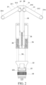
- a clamping apparatus which includes: a carrier portion 1, a movable unit 2 and a clamping unit 3.
- the carrier portion 1 is formed on a panel and a track slot is formed in a length direction in the carrier portion 1.
- the movable unit 2 is mounted at an end of the carrier portion 1 and the movable unit 2 is capable of separating from the carrier portion 1 along a length direction of the track slot.
- the clamping unit 3 is mounted on the movable unit 2 and the clamping unit 3 is configured to prevent, in at least four directions, a clamped object from being separated from the carrier portion 1.
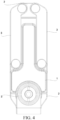
- the carrier portion 1 is specifically a cuboid that is hollow.
- Three track slots are formed through isolation in the length direction in the cuboid and each track slot is provided with an opening.
- An opening of a track slot in the middle is located on a side wall of the cuboid in the length direction and openings of track slots on two sides are located on another side wall of the cuboid in the length direction.
- a T-shaped protrusion is formed on an upper surface of the cuboid and two sides of the T-shaped protrusion are dent downward relative to the T-shaped protrusion to form accommodation slots 11.
- the specific shape of the carrier portion 1 is not limited to cuboid and specifically.
- the carrier portion 1 may be a square column or elliptical according to different application scenarios.
- the movable unit 2 includes: a first sliding component 23, a second sliding component 24, a first elastic component 25, second elastic components 26, a first connecting member 21 and a second connecting member 22.
- the first sliding component 23 is specifically a sliding bar that has a cutout in the middle.
- the sliding bar is inserted into the track slot from the opening of the track slot in the middle of the carrier portion 1.
- An end of the sliding bar located in the track slot is provided with a U-shaped notch in the middle.
- the first sliding component 23 and the first elastic component 25 are cooperatively used and the first elastic component 25 is specifically a spiral spring.
- An end of the spiral spring is connected to the U-shaped notch of the sliding bar and the other end is connected to a side wall at the other end of the track slot in the middle.
- a hook is disposed on the side wall at the other end of the track slot and is configured to connect to the spiral spring.
- the first connecting member 21 is specifically a trapezoidal panel. Two legs of the trapezoidal panel are arc-shaped. The size of a relatively longer edge of the trapezoidal panel is completely consistent with that of a side edge of the carrier portion 1 provided with a track slot. The relatively longer edge of the trapezoidal panel is connected to the end of the sliding bar extending out of the track slot.
- the trapezoidal panel is capable of preventing the sliding bar from excessively deeply extending into the track slot, so that the spiral spring keeps applying a tensile deformation force to the sliding bar.
- the first sliding component 23 is specifically a column.
- the column is inserted into the track slot from the opening of the track slot in the middle of the carrier portion 1.
- An end of the column located in the track slot protrudes to form a stopping edge.
- the sectional area of the stopping edge is greater than the sectional area of the column and is also greater than the sectional area of the opening of the track slot.
- the first sliding component 23 and the first elastic component 25 are cooperatively used.
- the first elastic component 25 is specifically a spiral spring. The spiral spring is sleeved over the column.
- the sectional area of the spiral spring is less than the sectional area of the stopping edge but is greater than the sectional area of the opening of the track slot.
- the first connecting member 21 is specifically a trapezoidal panel. Two legs of the trapezoidal panel are arc-shaped. The size of a relatively longer edge of the trapezoidal panel is completely consistent with that of a side edge of the carrier portion 1 provided with a track slot. The relatively longer edge of the trapezoidal panel is connected to the end of the column extending out of the track slot. Because the sectional area of an end of the trapezoidal panel connected to the column is greater than that of the opening of the track slot, the trapezoidal panel is capable of preventing the column from excessively deeply extending into the track slot, so that the spiral spring keeps applying an elastic deformation force to the column.
- the second sliding component 24 is specifically a first column and a second column.
- the first column is completely consistent with the second column. Take the first column as an example for description.
- the first column is inserted into a track slot from an opening of the track slot on the left of the carrier portion 1.
- An end of the first column located in the track slot also protrudes to form a stopping edge.
- the sectional area of the stopping edge is greater than the sectional area of the column and is also greater than the sectional area of the opening of the track slot.
- the second column is located in a track slot on the right.
- the second sliding component 24 and the second elastic components 26 are cooperatively used and the second elastic components are specifically two spiral springs. The two spiral springs are respectively sleeved over the first column and the second column.
- the sectional area of the spiral spring is less than the sectional area of the stopping edge but is greater than the sectional area of the opening of the track slot.
- the second connecting member 22 is specifically a trapezoid-type panel. An end of the trapezoid-type panel that is not connected to the first column and the second column is dent inward to form a clamping slot 221. Two legs of the trapezoid-type panel are arc-shaped. The size of a relatively longer edge of the trapezoid-type panel is completely consistent with the size of the side edge of the carrier portion 1.
- the relatively longer edge of the trapezoid-type panel is connected to the end of each of the first column and the second column extending out of the track slot. Because the sectional area of an end of the trapezoid-type panel connected to the first column and the second column is greater than that of the opening of the track slot, the trapezoid-type panel is capable of preventing the first column and the second column from excessively deeply extending into the track slot, so that the spiral springs each keep applying an elastic deformation force to the first column and the second column.
- the clamping unit 3 includes a swing component 31 and a clamping member 32.
- the swing component 31 is mounted on the first connecting member 21 and is configured to prevent, in at least three directions, the clamped object from being separated from the carrier portion 1.
- the clamping member 32 is mounted to the second connecting member 22 and is configured to prevent, in at least one direction, the clamped object from being separated from the carrier portion 1.
- a connector 33 is disposed at an end of the clamping member 32 and the connector 33 is flush with the end of the clamping member 32.
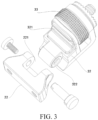
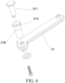
- the swing component 31 includes a first swing rod 311 and a second swing rod 312.
- An end of the first swing rod 311 is mounted on an upper surface of the first connecting member 21 and the first swing rod 311 and the first connecting member 21 are connected together by using a shaft.
- the first swing rod 311 is capable of rotating around a shaft connecting portion, so that the first swing rod 311 is capable of arcing away from the carrier portion 1.
- the second swing rod 312 and the first swing rod 311 are symmetrically connected to the upper surface of the first connecting member 21 and the second swing rod 312 is also capable of arcing away from the carrier portion 1.
- the clamping member 32 is mounted on an L-shaped panel 323.
- the clamping member 32 is mounted on an inner surface of the L-shaped panel 323 and an end of the L-shaped panel 323 is connected to a cylindrical column 322 provided with an axle hole in the middle.
- the cylindrical column 322 cooperates with the clamping slot 221 of the second connecting member 22 and the cylindrical column 322 protrudes into the clamping slot 221.
- Two side walls of the clamping slot 221 are provided with through holes cooperating with the axle hole.
- the through holes and the axle hole are located on a same straight line and implement an axle connection by using an inserted rotating shaft.
- the L-shaped panel 323 drives the clamping member 32 to be capable of rotating by 90° relative to the second connecting member 22. As shown in FIG.
- the L-shaped panel 323 is further connected to a connector 33 and the connector 33 is connected to the same end of the clamping member 32 in the L-shaped panel 323.
- the connector 33 includes a screw 331, a foam cushion 332, a nut 333, a gasket 334, a plastic gasket 335 and a flange shaft 336.
- An end of the L-shaped panel 323 parallel with the gasket 334 is provided with a through hole for insertion by the flange shaft 336.
- the screw 331, the foam cushion 332, the nut 333, the gasket 334 and the plastic gasket 335 are located in a gap between the L-shaped panel 323 and the clamping member 32.
Landscapes
- Engineering & Computer Science (AREA)
- General Engineering & Computer Science (AREA)
- Mechanical Engineering (AREA)
- Aviation & Aerospace Engineering (AREA)
- Microelectronics & Electronic Packaging (AREA)
- Remote Sensing (AREA)
- Clamps And Clips (AREA)
Claims (6)
- Klemmvorrichtung, umfassend:einen Trägerabschnitt (1), der auf einer Platte ausgebildet ist, wobei in einer Längenrichtung im Trägerabschnitt (1) ein Führungsschlitz ausgebildet ist;wobei eine vertikale Richtung bei Gebrauch die Längenrichtung des Trägerabschnitts (1) ist,wobei eine horizontale Richtung bei Gebrauch eine Breitenrichtung des Trägerabschnitts (1) senkrecht zur Längenrichtung des Trägerabschnitts (1) ist;eine bewegbare Einheit (2), die an einem Ende des Trägerabschnitts (1) montiert und in der Lage ist, entlang einer Längenrichtung des Führungsschlitzes vom Trägerabschnitt (1) gelöst zu werden, wobei die bewegbare Einheit (2) ein erstes Verbindungselement (21), ein zweites Verbindungselement (22), eine erste Gleitkomponente (23), eine zweite Gleitkomponente (24), eine erste elastische Komponente (25) und eine zweite elastische Komponente (26) umfasst; undeine Klemmeinheit (3), die an der bewegbaren Einheit (2) montiert und dazu ausgestaltet ist, in vier Richtungen zu verhindern, dass sich ein festgeklemmtes Objekt vom Trägerabschnitt (1) löst;wobei die Klemmeinheit (3) Folgendes umfasst:eine Schwenkkomponente (31), wobei die Schwenkkomponente (31) am ersten Verbindungselement (21) montiert und dazu ausgestaltet ist, in drei Richtungen zu verhindern, dass sich das festgeklemmte Objekt vom Trägerabschnitt (1) löst; undein Klemmelement (32), wobei das Klemmelement (32) am zweiten Verbindungselement (22) montiert und dazu ausgestaltet ist, in einer Richtung zu verhindern, dass sich das festgeklemmte Objekt vom Trägerabschnitt (1) löst;wobei die Schwenkkomponente (31) eine erste Schwenkstange (311) und eine zweite Schwenkstange (312) umfasst, wobei sowohl die erste Schwenkstange (311) als auch die zweite Schwenkstange (312) unter Verwendung einer sich drehenden Welle mit dem ersten Verbindungselement (21) verbunden ist;wobei ein erstes Anschlagelement (313) und ein zweites Anschlagelement (314) entsprechend an zwei Enden der ersten Schwenkstange (311) montiert sind, und ein drittes Anschlagelement (315) und ein viertes Anschlagelement (316) entsprechend an zwei Enden der zweiten Schwenkstange (312) montiert sind;wobei die erste Schwenkstange (311) und die zweite Schwenkstange (312) derart am ersten Verbindungselement (21) montiert sind, dass sich die erste Schwenkstange (311) und die zweite Schwenkstange (312) vom Trägerabschnitt (1) wegbiegen; wobei sich die erste Schwenkstange (311) und die zweite Schwenkstange (312) bei Gebrauch vom Trägerabschnitt (1) in einer Ebene wegbiegen, die von der vertikalen Richtung und der horizontalen Richtung aufgespannt wird;wobei das erste Anschlagelement (313) und das dritte Anschlagelement (315) dazu ausgestaltet sind, zu verhindern, dass sich das festgeklemmte Objekt bei Gebrauch entlang der vertikalen Richtung vom Trägerabschnitt (1) löst, und das zweite Anschlagelement (314) und das vierte Anschlagelement (316) dazu ausgestaltet sind, zu verhindern, dass sich das festgeklemmte Objekt bei Gebrauch entlang der horizontalen Richtung vom Trägerabschnitt (1) löst; wobei das erste Anschlagelement (313) und das zweite Anschlagelement (314) an gegenüberliegenden Positionen der ersten Schwenkstange (311) angeordnet sind, sodass, wenn zwischen dem ersten Anschlagelement (313) und dem festgeklemmten Objekt eine Wechselwirkungskraft erzeugt wird, sich das zweite Anschlagelement (314) mit der ersten Schwenkstange (311) bewegt, bis das zweite Anschlagelement (314) mit dem festgeklemmten Objekt in Kontakt kommt;wobei das dritte Anschlagelement (315) und das vierte Anschlagelement (316) an gegenüberliegenden Positionen der zweiten Schwenkstange (312) angeordnet sind, sodass, wenn zwischen dem dritten Anschlagelement (315) und dem festgeklemmten Objekt eine Wechselwirkungskraft erzeugt wird, sich das vierte Anschlagelement (316) mit der zweiten Schwenkstange (312) bewegt, bis das vierte Anschlagelement (316) mit dem festgeklemmten Objekt in Kontakt kommt;wobei sowohl die erste Gleitkomponente (23) als auch die zweite Gleitkomponente (24) im Trägerabschnitt (1) angeordnet sind, wobei sich die erste Gleitkomponente (23) aus einem Ende des Trägerabschnitts (1) heraus entlang der Längenrichtung des Führungsschlitzes erstreckt und sich die zweite Gleitkomponente (24) aus dem anderen Ende des Trägerabschnitts (1) heraus entlang der Längenrichtung des Führungsschlitzes erstreckt;wobei die erste elastische Komponente (25) über die erste Gleitkomponente (23) gezogen oder damit verbunden ist, die zweite elastische Komponente (26) über die zweite Gleitkomponente (24) gezogen ist, die erste elastische Komponente (25) und die zweite elastische Komponente (26) jeweils beständig eine elastische Kraft auf die erste Gleitkomponente (23) und die zweite Gleitkomponente (24) ausüben; undwobei das erste Verbindungselement (21) an einem Ende der ersten Gleitkomponente (23) angeordnet ist, das zweite Verbindungselement (22) an einem Ende der zweiten Gleitkomponente (24) angeordnet ist, das erste Verbindungselement (21) und das zweite Verbindungselement (22) entsprechend dazu ausgestaltet sind, zu verhindern, dass sich die erste Gleitkomponente (23) und die zweite Gleitkomponente (24) zu tief in den Trägerabschnitt (1) hinein erstrecken.
- Klemmvorrichtung nach Anspruch 1, wobei das Klemmelement (32) eine Einkerbung nach innen aufweist, um eine Aussparung (321) auszubilden, und die Aussparung (321) derart ausgestaltet ist, dass das festgeklemmte Objekt teilweise in die Aussparung (321) hineingelassen wird.
- Klemmvorrichtung nach einem der vorangehenden Ansprüche, wobei ein Verbinder (33) an einem Ende des Klemmelements (32) angeordnet ist und der Verbinder (33) bündig mit dem Ende des Klemmelements (32) abschließt.
- Klemmvorrichtung nach einem der vorangehenden Ansprüche, wobei ein erstes Begrenzungselement (27) und ein zweites Begrenzungselement (28) am ersten Verbindungselement (21) montiert sind, wobei das erste Begrenzungselement (27) und das zweite Begrenzungselement (28) dazu ausgestaltet sind, zu verhindern, dass sich die erste Schwenkstange (311) und die zweite Schwenkstange (312) zu weit weg vom Trägerabschnitt (1) befindet.
- Klemmvorrichtung nach Anspruch 4, wobei ein Abschnitt der ersten Schwenkstange (311) nahe dem ersten Begrenzungselement (27) derart ausgestaltet ist, dass die erste Schwenkstange (311) keinen Kontakt zum ersten Begrenzungselement (27) hat oder nicht dadurch begrenzt wird, wenn die erste Schwenkstange (311) um einen bestimmten Bereich vom Trägerabschnitt (1) entfernt ist; und
ein Abschnitt der zweiten Schwenkstange (312) nahe dem zweiten Begrenzungselement (28) derart ausgestaltet ist, dass die zweite Schwenkstange (312) keinen Kontakt zum zweiten Begrenzungselement (28) hat oder nicht dadurch begrenzt wird, wenn die zweite Schwenkstange (312) um einen bestimmten Bereich vom Trägerabschnitt (1) entfernt ist. - Gimbal eines unbemannten Luftfahrzeugs, wobei die Klemmvorrichtung nach einem der vorangehenden Ansprüche mit dem Gimbal des unbemannten Luftfahrzeugs verbunden ist.
Applications Claiming Priority (2)
| Application Number | Priority Date | Filing Date | Title |
|---|---|---|---|
| CN201620278463.9U CN205480104U (zh) | 2016-04-06 | 2016-04-06 | 一种夹持装置及无人机云台 |
| PCT/CN2016/092729 WO2017173747A1 (zh) | 2016-04-06 | 2016-08-01 | 一种夹持装置及无人机云台 |
Publications (3)
| Publication Number | Publication Date |
|---|---|
| EP3366972A1 EP3366972A1 (de) | 2018-08-29 |
| EP3366972A4 EP3366972A4 (de) | 2019-01-09 |
| EP3366972B1 true EP3366972B1 (de) | 2025-07-09 |
Family
ID=56645834
Family Applications (1)
| Application Number | Title | Priority Date | Filing Date |
|---|---|---|---|
| EP16897680.1A Active EP3366972B1 (de) | 2016-04-06 | 2016-08-01 | Haltevorrichtung und ptz-mechanismus eines unbemannten luftfahrzeugs |
Country Status (4)
| Country | Link |
|---|---|
| US (1) | US10550991B2 (de) |
| EP (1) | EP3366972B1 (de) |
| CN (1) | CN205480104U (de) |
| WO (1) | WO2017173747A1 (de) |
Families Citing this family (2)
| Publication number | Priority date | Publication date | Assignee | Title |
|---|---|---|---|---|
| CN106402615B (zh) * | 2016-11-21 | 2018-06-15 | 深圳市高巨创新科技开发有限公司 | 一种夹持装置 |
| US20250108766A1 (en) * | 2023-09-29 | 2025-04-03 | Rivian Ip Holdings, Llc | Retention apparatus for vehicles and related methods |
Family Cites Families (16)
| Publication number | Priority date | Publication date | Assignee | Title |
|---|---|---|---|---|
| US6220589B1 (en) * | 2000-01-05 | 2001-04-24 | Adjustable Clamp Company | Dual action clamp |
| US7571522B2 (en) * | 2003-08-07 | 2009-08-11 | Carnevali Jeffrey D | Quick draw cradle apparatus |
| DE102004062177B4 (de) * | 2004-12-21 | 2007-10-04 | Bury Sp.Z.O.O | Haltevorrichtung zur Aufnahme eines Mobiltelefons |
| US7380765B2 (en) * | 2005-08-16 | 2008-06-03 | Shiff Harold H | Adjustable easel for supporting a workpiece |
| US9568148B2 (en) * | 2007-02-26 | 2017-02-14 | Jeffrey D. Carnevali | Finger grip mounting apparatus |
| KR101252095B1 (ko) * | 2011-03-18 | 2013-04-12 | 여영규 | 휴대용 기기를 위한 홀더 |
| US20140183238A1 (en) * | 2012-12-30 | 2014-07-03 | Rocky Yi-Ping LIN | Portable electronic device holder for car |
| US8752802B1 (en) * | 2013-02-27 | 2014-06-17 | Eagle Fan | Clamping device adapted to electronic product of different dimensions |
| KR20140005297U (ko) * | 2013-04-02 | 2014-10-13 | 송해성 | 휴대폰 홀더 |
| CN203286232U (zh) * | 2013-05-16 | 2013-11-13 | 中山立信摄影器材有限公司 | 一种新型云台锁紧装置 |
| US9062818B2 (en) * | 2013-07-23 | 2015-06-23 | Eagle Fan | Clamping apparatus |
| CN112429255A (zh) * | 2014-04-28 | 2021-03-02 | 深圳市大疆创新科技有限公司 | 手持式平台 |
| CN103994310B (zh) * | 2014-06-06 | 2016-12-07 | 威宝摄影器材有限公司 | 一种便携式移动终端夹持装置 |
| CN104386249B (zh) * | 2014-11-17 | 2016-03-30 | 马鞍山市靓马航空科技有限公司 | 一种快速测绘多旋翼无人机的测绘方法 |
| CN204647755U (zh) * | 2015-05-13 | 2015-09-16 | 奇酷互联网络科技(深圳)有限公司 | 夹持装置及自拍杆 |
| CN204964966U (zh) * | 2015-08-10 | 2016-01-13 | 深圳市大疆创新科技有限公司 | 夹持结构及具有该夹持结构的云台 |
-
2016
- 2016-04-06 CN CN201620278463.9U patent/CN205480104U/zh not_active Expired - Lifetime
- 2016-08-01 EP EP16897680.1A patent/EP3366972B1/de active Active
- 2016-08-01 WO PCT/CN2016/092729 patent/WO2017173747A1/zh not_active Ceased
-
2018
- 2018-06-11 US US16/004,931 patent/US10550991B2/en active Active
Also Published As
| Publication number | Publication date |
|---|---|
| US20180292042A1 (en) | 2018-10-11 |
| CN205480104U (zh) | 2016-08-17 |
| US10550991B2 (en) | 2020-02-04 |
| EP3366972A1 (de) | 2018-08-29 |
| WO2017173747A1 (zh) | 2017-10-12 |
| EP3366972A4 (de) | 2019-01-09 |
Similar Documents
| Publication | Publication Date | Title |
|---|---|---|
| US11085574B2 (en) | Handheld gimbal and handheld structure | |
| KR101978586B1 (ko) | 스크린 확장 구조체, 가요성 스크린 조립체 및 단말기 | |
| JP6574855B2 (ja) | 位置規制装置、およびこの位置規制装置を有する無人航空機 | |
| US10845680B2 (en) | Gimbal photographing device | |
| US8720837B2 (en) | Support frame for electronic device | |
| US9304553B2 (en) | Convertible computing apparatus | |
| CN108980587A (zh) | 手持云台 | |
| US8633991B2 (en) | Image stabilization of compact imaging device | |
| CN205452519U (zh) | 内置天线结构及无人机 | |
| US10809542B2 (en) | Rolling magnetic driving unit and optical unit with shake correction function | |
| WO2018132990A1 (zh) | 云台组件及手持云台拍摄器 | |
| JP6394778B2 (ja) | 携帯端末および携帯端末のカメラアセンブリ | |
| US9625793B1 (en) | Mounting apparatus for position-retaining camera | |
| US20160195117A1 (en) | Alignment structure | |
| CN105096570B (zh) | 遥控装置及应用所述遥控装置的遥控系统 | |
| US10550991B2 (en) | Clamping apparatus and unmanned aerial vehicle gimbal | |
| US20120182470A1 (en) | Communication apparatus | |
| CN206409866U (zh) | 用于拍摄的手持装置 | |
| KR200479601Y1 (ko) | 다용도 휴대폰 케이스 | |
| CN204305154U (zh) | 电子设备 | |
| JP5561771B2 (ja) | 筐体を備える機器、及び、携帯機器 | |
| CN108253272A (zh) | 手持云台的配重结构 | |
| US20240264512A1 (en) | Camera assembly and electronic device | |
| CN107466490A (zh) | 转轴组件、转动连接机构、夹持装置及手持设备 | |
| US20190195418A1 (en) | Ptz assembly and a clamping mechanism thereof |
Legal Events
| Date | Code | Title | Description |
|---|---|---|---|
| STAA | Information on the status of an ep patent application or granted ep patent |
Free format text: STATUS: THE INTERNATIONAL PUBLICATION HAS BEEN MADE |
|
| PUAI | Public reference made under article 153(3) epc to a published international application that has entered the european phase |
Free format text: ORIGINAL CODE: 0009012 |
|
| STAA | Information on the status of an ep patent application or granted ep patent |
Free format text: STATUS: REQUEST FOR EXAMINATION WAS MADE |
|
| 17P | Request for examination filed |
Effective date: 20180507 |
|
| AK | Designated contracting states |
Kind code of ref document: A1 Designated state(s): AL AT BE BG CH CY CZ DE DK EE ES FI FR GB GR HR HU IE IS IT LI LT LU LV MC MK MT NL NO PL PT RO RS SE SI SK SM TR |
|
| AX | Request for extension of the european patent |
Extension state: BA ME |
|
| A4 | Supplementary search report drawn up and despatched |
Effective date: 20181210 |
|
| RIC1 | Information provided on ipc code assigned before grant |
Ipc: B64D 47/08 20060101ALI20181204BHEP Ipc: F16M 13/02 20060101ALI20181204BHEP Ipc: B64C 39/02 20060101ALI20181204BHEP Ipc: F16M 11/04 20060101AFI20181204BHEP |
|
| DAV | Request for validation of the european patent (deleted) | ||
| DAX | Request for extension of the european patent (deleted) | ||
| STAA | Information on the status of an ep patent application or granted ep patent |
Free format text: STATUS: EXAMINATION IS IN PROGRESS |
|
| 17Q | First examination report despatched |
Effective date: 20210525 |
|
| GRAP | Despatch of communication of intention to grant a patent |
Free format text: ORIGINAL CODE: EPIDOSNIGR1 |
|
| STAA | Information on the status of an ep patent application or granted ep patent |
Free format text: STATUS: GRANT OF PATENT IS INTENDED |
|
| RIC1 | Information provided on ipc code assigned before grant |
Ipc: B64U 101/30 20230101ALN20250115BHEP Ipc: B64U 20/87 20230101ALI20250115BHEP Ipc: F16M 13/02 20060101ALI20250115BHEP Ipc: F16M 11/04 20060101AFI20250115BHEP |
|
| INTG | Intention to grant announced |
Effective date: 20250213 |
|
| GRAS | Grant fee paid |
Free format text: ORIGINAL CODE: EPIDOSNIGR3 |
|
| GRAA | (expected) grant |
Free format text: ORIGINAL CODE: 0009210 |
|
| STAA | Information on the status of an ep patent application or granted ep patent |
Free format text: STATUS: THE PATENT HAS BEEN GRANTED |
|
| AK | Designated contracting states |
Kind code of ref document: B1 Designated state(s): AL AT BE BG CH CY CZ DE DK EE ES FI FR GB GR HR HU IE IS IT LI LT LU LV MC MK MT NL NO PL PT RO RS SE SI SK SM TR |
|
| REG | Reference to a national code |
Ref country code: GB Ref legal event code: FG4D |
|
| REG | Reference to a national code |
Ref country code: CH Ref legal event code: EP |
|
| REG | Reference to a national code |
Ref country code: IE Ref legal event code: FG4D |
|
| REG | Reference to a national code |
Ref country code: DE Ref legal event code: R096 Ref document number: 602016092878 Country of ref document: DE |
|
| PGFP | Annual fee paid to national office [announced via postgrant information from national office to epo] |
Ref country code: DE Payment date: 20250820 Year of fee payment: 10 |
|
| PGFP | Annual fee paid to national office [announced via postgrant information from national office to epo] |
Ref country code: FR Payment date: 20250903 Year of fee payment: 10 |
|
| REG | Reference to a national code |
Ref country code: NL Ref legal event code: MP Effective date: 20250709 |
|
| PG25 | Lapsed in a contracting state [announced via postgrant information from national office to epo] |
Ref country code: PT Free format text: LAPSE BECAUSE OF FAILURE TO SUBMIT A TRANSLATION OF THE DESCRIPTION OR TO PAY THE FEE WITHIN THE PRESCRIBED TIME-LIMIT Effective date: 20251110 |
|
| PG25 | Lapsed in a contracting state [announced via postgrant information from national office to epo] |
Ref country code: NL Free format text: LAPSE BECAUSE OF FAILURE TO SUBMIT A TRANSLATION OF THE DESCRIPTION OR TO PAY THE FEE WITHIN THE PRESCRIBED TIME-LIMIT Effective date: 20250709 |
|
| REG | Reference to a national code |
Ref country code: AT Ref legal event code: MK05 Ref document number: 1812089 Country of ref document: AT Kind code of ref document: T Effective date: 20250709 |
|
| PG25 | Lapsed in a contracting state [announced via postgrant information from national office to epo] |
Ref country code: IS Free format text: LAPSE BECAUSE OF FAILURE TO SUBMIT A TRANSLATION OF THE DESCRIPTION OR TO PAY THE FEE WITHIN THE PRESCRIBED TIME-LIMIT Effective date: 20251109 |
|
| PG25 | Lapsed in a contracting state [announced via postgrant information from national office to epo] |
Ref country code: NO Free format text: LAPSE BECAUSE OF FAILURE TO SUBMIT A TRANSLATION OF THE DESCRIPTION OR TO PAY THE FEE WITHIN THE PRESCRIBED TIME-LIMIT Effective date: 20251009 |
|
| REG | Reference to a national code |
Ref country code: LT Ref legal event code: MG9D |
|
| PG25 | Lapsed in a contracting state [announced via postgrant information from national office to epo] |
Ref country code: AT Free format text: LAPSE BECAUSE OF FAILURE TO SUBMIT A TRANSLATION OF THE DESCRIPTION OR TO PAY THE FEE WITHIN THE PRESCRIBED TIME-LIMIT Effective date: 20250709 |
|
| PG25 | Lapsed in a contracting state [announced via postgrant information from national office to epo] |
Ref country code: FI Free format text: LAPSE BECAUSE OF FAILURE TO SUBMIT A TRANSLATION OF THE DESCRIPTION OR TO PAY THE FEE WITHIN THE PRESCRIBED TIME-LIMIT Effective date: 20250709 |
|
| PG25 | Lapsed in a contracting state [announced via postgrant information from national office to epo] |
Ref country code: HR Free format text: LAPSE BECAUSE OF FAILURE TO SUBMIT A TRANSLATION OF THE DESCRIPTION OR TO PAY THE FEE WITHIN THE PRESCRIBED TIME-LIMIT Effective date: 20250709 |
|
| PG25 | Lapsed in a contracting state [announced via postgrant information from national office to epo] |
Ref country code: GR Free format text: LAPSE BECAUSE OF FAILURE TO SUBMIT A TRANSLATION OF THE DESCRIPTION OR TO PAY THE FEE WITHIN THE PRESCRIBED TIME-LIMIT Effective date: 20251010 |
|
| PG25 | Lapsed in a contracting state [announced via postgrant information from national office to epo] |
Ref country code: SE Free format text: LAPSE BECAUSE OF FAILURE TO SUBMIT A TRANSLATION OF THE DESCRIPTION OR TO PAY THE FEE WITHIN THE PRESCRIBED TIME-LIMIT Effective date: 20250709 |
|
| PG25 | Lapsed in a contracting state [announced via postgrant information from national office to epo] |
Ref country code: LV Free format text: LAPSE BECAUSE OF FAILURE TO SUBMIT A TRANSLATION OF THE DESCRIPTION OR TO PAY THE FEE WITHIN THE PRESCRIBED TIME-LIMIT Effective date: 20250709 |
|
| PG25 | Lapsed in a contracting state [announced via postgrant information from national office to epo] |
Ref country code: PL Free format text: LAPSE BECAUSE OF FAILURE TO SUBMIT A TRANSLATION OF THE DESCRIPTION OR TO PAY THE FEE WITHIN THE PRESCRIBED TIME-LIMIT Effective date: 20250709 Ref country code: BG Free format text: LAPSE BECAUSE OF FAILURE TO SUBMIT A TRANSLATION OF THE DESCRIPTION OR TO PAY THE FEE WITHIN THE PRESCRIBED TIME-LIMIT Effective date: 20250709 |
|
| PG25 | Lapsed in a contracting state [announced via postgrant information from national office to epo] |
Ref country code: RS Free format text: LAPSE BECAUSE OF FAILURE TO SUBMIT A TRANSLATION OF THE DESCRIPTION OR TO PAY THE FEE WITHIN THE PRESCRIBED TIME-LIMIT Effective date: 20251009 |
|
| PG25 | Lapsed in a contracting state [announced via postgrant information from national office to epo] |
Ref country code: ES Free format text: LAPSE BECAUSE OF FAILURE TO SUBMIT A TRANSLATION OF THE DESCRIPTION OR TO PAY THE FEE WITHIN THE PRESCRIBED TIME-LIMIT Effective date: 20250709 |
|
| PG25 | Lapsed in a contracting state [announced via postgrant information from national office to epo] |
Ref country code: RO Free format text: LAPSE BECAUSE OF FAILURE TO SUBMIT A TRANSLATION OF THE DESCRIPTION OR TO PAY THE FEE WITHIN THE PRESCRIBED TIME-LIMIT Effective date: 20250709 |
|
| REG | Reference to a national code |
Ref country code: CH Ref legal event code: H13 Free format text: ST27 STATUS EVENT CODE: U-0-0-H10-H13 (AS PROVIDED BY THE NATIONAL OFFICE) Effective date: 20260324 |
|
| PG25 | Lapsed in a contracting state [announced via postgrant information from national office to epo] |
Ref country code: SM Free format text: LAPSE BECAUSE OF FAILURE TO SUBMIT A TRANSLATION OF THE DESCRIPTION OR TO PAY THE FEE WITHIN THE PRESCRIBED TIME-LIMIT Effective date: 20250709 |
|
| PG25 | Lapsed in a contracting state [announced via postgrant information from national office to epo] |
Ref country code: DK Free format text: LAPSE BECAUSE OF FAILURE TO SUBMIT A TRANSLATION OF THE DESCRIPTION OR TO PAY THE FEE WITHIN THE PRESCRIBED TIME-LIMIT Effective date: 20250709 |
|
| PG25 | Lapsed in a contracting state [announced via postgrant information from national office to epo] |
Ref country code: LU Free format text: LAPSE BECAUSE OF NON-PAYMENT OF DUE FEES Effective date: 20250801 Ref country code: IT Free format text: LAPSE BECAUSE OF FAILURE TO SUBMIT A TRANSLATION OF THE DESCRIPTION OR TO PAY THE FEE WITHIN THE PRESCRIBED TIME-LIMIT Effective date: 20250709 |
|
| PG25 | Lapsed in a contracting state [announced via postgrant information from national office to epo] |
Ref country code: CH Free format text: LAPSE BECAUSE OF NON-PAYMENT OF DUE FEES Effective date: 20250831 Ref country code: CZ Free format text: LAPSE BECAUSE OF FAILURE TO SUBMIT A TRANSLATION OF THE DESCRIPTION OR TO PAY THE FEE WITHIN THE PRESCRIBED TIME-LIMIT Effective date: 20250709 |
|
| PG25 | Lapsed in a contracting state [announced via postgrant information from national office to epo] |
Ref country code: EE Free format text: LAPSE BECAUSE OF FAILURE TO SUBMIT A TRANSLATION OF THE DESCRIPTION OR TO PAY THE FEE WITHIN THE PRESCRIBED TIME-LIMIT Effective date: 20250709 Ref country code: SK Free format text: LAPSE BECAUSE OF FAILURE TO SUBMIT A TRANSLATION OF THE DESCRIPTION OR TO PAY THE FEE WITHIN THE PRESCRIBED TIME-LIMIT Effective date: 20250709 |
|
| PLBE | No opposition filed within time limit |
Free format text: ORIGINAL CODE: 0009261 |
|
| STAA | Information on the status of an ep patent application or granted ep patent |
Free format text: STATUS: NO OPPOSITION FILED WITHIN TIME LIMIT |