EP3366961A1 - Membranventil mit freiem durchgang - Google Patents
Membranventil mit freiem durchgang Download PDFInfo
- Publication number
- EP3366961A1 EP3366961A1 EP18150573.6A EP18150573A EP3366961A1 EP 3366961 A1 EP3366961 A1 EP 3366961A1 EP 18150573 A EP18150573 A EP 18150573A EP 3366961 A1 EP3366961 A1 EP 3366961A1
- Authority
- EP
- European Patent Office
- Prior art keywords
- membrane
- valve
- edge
- curved
- hood
- Prior art date
- Legal status (The legal status is an assumption and is not a legal conclusion. Google has not performed a legal analysis and makes no representation as to the accuracy of the status listed.)
- Granted
Links
Images



Classifications
-
- F—MECHANICAL ENGINEERING; LIGHTING; HEATING; WEAPONS; BLASTING
- F16—ENGINEERING ELEMENTS AND UNITS; GENERAL MEASURES FOR PRODUCING AND MAINTAINING EFFECTIVE FUNCTIONING OF MACHINES OR INSTALLATIONS; THERMAL INSULATION IN GENERAL
- F16K—VALVES; TAPS; COCKS; ACTUATING-FLOATS; DEVICES FOR VENTING OR AERATING
- F16K27/00—Construction of housing; Use of materials therefor
- F16K27/02—Construction of housing; Use of materials therefor of lift valves
- F16K27/0236—Diaphragm cut-off apparatus
-
- F—MECHANICAL ENGINEERING; LIGHTING; HEATING; WEAPONS; BLASTING
- F16—ENGINEERING ELEMENTS AND UNITS; GENERAL MEASURES FOR PRODUCING AND MAINTAINING EFFECTIVE FUNCTIONING OF MACHINES OR INSTALLATIONS; THERMAL INSULATION IN GENERAL
- F16K—VALVES; TAPS; COCKS; ACTUATING-FLOATS; DEVICES FOR VENTING OR AERATING
- F16K7/00—Diaphragm valves or cut-off apparatus, e.g. with a member deformed, but not moved bodily, to close the passage ; Pinch valves
- F16K7/12—Diaphragm valves or cut-off apparatus, e.g. with a member deformed, but not moved bodily, to close the passage ; Pinch valves with flat, dished, or bowl-shaped diaphragm
- F16K7/126—Diaphragm valves or cut-off apparatus, e.g. with a member deformed, but not moved bodily, to close the passage ; Pinch valves with flat, dished, or bowl-shaped diaphragm the seat being formed on a rib perpendicular to the fluid line
-
- F—MECHANICAL ENGINEERING; LIGHTING; HEATING; WEAPONS; BLASTING
- F16—ENGINEERING ELEMENTS AND UNITS; GENERAL MEASURES FOR PRODUCING AND MAINTAINING EFFECTIVE FUNCTIONING OF MACHINES OR INSTALLATIONS; THERMAL INSULATION IN GENERAL
- F16K—VALVES; TAPS; COCKS; ACTUATING-FLOATS; DEVICES FOR VENTING OR AERATING
- F16K7/00—Diaphragm valves or cut-off apparatus, e.g. with a member deformed, but not moved bodily, to close the passage ; Pinch valves
- F16K7/12—Diaphragm valves or cut-off apparatus, e.g. with a member deformed, but not moved bodily, to close the passage ; Pinch valves with flat, dished, or bowl-shaped diaphragm
- F16K7/14—Diaphragm valves or cut-off apparatus, e.g. with a member deformed, but not moved bodily, to close the passage ; Pinch valves with flat, dished, or bowl-shaped diaphragm arranged to be deformed against a flat seat
- F16K7/16—Diaphragm valves or cut-off apparatus, e.g. with a member deformed, but not moved bodily, to close the passage ; Pinch valves with flat, dished, or bowl-shaped diaphragm arranged to be deformed against a flat seat the diaphragm being mechanically actuated, e.g. by screw-spindle or cam
Definitions
- the invention relates to a valve with a membrane having an edge which is arranged in a chamber, which is formed by a housing part and a hood.
- Diaphragm valves can be used to dose different fluids, such as gases, vapors or liquids.
- diaphragm valves can be used to meter or distribute highly viscous or very strongly adhesive media. In the case of diaphragm valves, this effectively prevents deposition and thus also contamination.
- Valves based on the membrane principle are the lowest-dead-weight dosing valves. In addition to the very low dead space volume, diaphragm valves are also designed to be emptying-optimized so that residue-free removal of the medium is possible.
- Diaphragm valves have established themselves as the preferred valve in the sterile process technology due to their advantageous design features.
- the membranes used form movable, sealing walls that separate two rooms with generally different media (gases, liquids) and often also different pressure ratios.
- An important quality feature of a membrane is its mobility, that is the ability perpendicular to the clamping surface (membrane surface) to perform a stroke that may be mechanically driven conditional. Furthermore, the durability of the membrane is important, especially when aggressive media are promoted.
- the mobility and durability of a membrane depends essentially on the material of which the membrane is made.
- As base materials for membranes mainly elastomers are used, which can be reinforced for greater strength with fabric inserts.
- As elastomers membranes have proven with ethylene-propylene-diene rubber (EPDM).
- EPDM ethylene-propylene-diene rubber
- EPDM is a terpolymeric elastomer (rubber) and thus synthetic rubber. The material is characterized by a high elasticity and good chemical resistance.
- a diaphragm valve which consists of a housing having an upper housing part and a lower housing part. Between the two housing parts, a membrane is clamped, which has a bead. By means of a screw located outside of the edge bead, the membrane is clamped in a chamber which is formed by the upper housing part and the lower housing part. At the edge bead an external lobe-like extension is formed. The tab-like extension is arranged between the corresponding end faces of the upper housing part and the lower housing part.
- the clamping area of a valve diaphragm is subject to special requirements. First and foremost, it serves to hold the membrane, the edge region of which is exposed during the closing and in the closed position, a radially inwardly directed train. If no additional seal between the base and the top is provided of the housing, the clamped between the housing parts edge can also take on the task of resting seal.
- the problem is not or only to a small extent given.
- the surface pressure exerted on the edge bead need not be as high as a flat edge because the large-sized bead adapts to the chamber receiving it, thus ensuring a good seal.
- the chambering of the clamping area ensures a permanent holder.
- the edge bead entails a problem in itself, which has its cause in a non-exclude improper installation or maintenance. Namely, if the prescribed by the manufacturer of such a diaphragm valve tightening torque of the screw is exceeded by a considerable amount, there is a radially inwardly directed displacement of a portion of the membrane material of the edge bead. At the all around extending the chamber limiting bottleneck, which is formed by the two housing parts, this results in an accumulation of material, which leads to stresses in this and in the adjacent membrane area, especially during the membrane actuation. These tensions can eventually lead to a rupture of the membrane surface and, at least in membranes without fiber reinforcement, ultimately to a membrane rupture.
- the edge bead, this receiving chamber and the end faces of housing lower and upper part could be designed and dimensioned so that the maximum allowable pressure of the edge bead would be achieved if the end faces of the housing parts would come to rest against each other.
- a valve with a membrane is described. Between a housing part and a hood, the membrane is clamped. The actuation of the membrane attached to a pressure piece via a spindle by means of a handwheel.
- the membrane is equipped with a reinforcement fabric. It has at its edge a Befest Trentswulst, which is supported in a chamber formed by the housing part and the valve cover.
- Membrane valves on the market are available with diaphragm and diaphragm valves with free passage. Barrier diaphragm valves are mainly used for pumping non-solids fluids.
- the diaphragm valve has a flat membrane, which ensures a long service life even at high switching cycles. Furthermore, there is a large spectrum of usable materials for membrane valves with web. In addition, such membrane valves with web are also suitable for higher pressures due to the support of the membrane with a spiral.
- diaphragm valves with free passage can also be used for solids-containing media, since no web is present as an increase in the pipeline and thus the risk of abrasion is significantly lower.
- Such membrane valves without web, which have a free passage can also be used for highly solids-containing media, as they occur, for example, in the removal of rocks by water, for example when drilling in layers of soil.
- Disadvantages of such free passage valves are the low durability of the diaphragm, which occurs due to the great deformation during opening and closing.
- such valves with free passage so without a protruding through the pipe web less diversity in the selection of materials.
- such valves have a lower compressive strength due to the lack of support of the membrane.
- the object of the invention is to provide a diaphragm valve which has the lowest possible abrasion even when conveying solids-containing media.
- the valve should be characterized by the lowest possible load on the diaphragm valve during operation, so that the membrane is characterized by a relatively long service life. Furthermore, a reliable seal of the valve should be ensured so that no medium leaks.
- the valve should be characterized by low flow losses or pressure losses in the promotion and thus by a high performance.
- the diaphragm valve should be as inexpensive to manufacture and ensure flexible use in different applications.
- the chamber in which the membrane is arranged and / or the edge of the membrane is arched.
- the diaphragm is clamped between a housing member and a hood in a space formed in a horizontal plane.
- the chambering of the valve according to the invention is arched and is not in a horizontal plane, but is curved downwards.
- the valve according to the invention While in conventional diaphragm valves, the region in which the membrane rests, is formed flat, the valve according to the invention has a bent portion in which the membrane rests. This bend allows for a relatively free passage and at the same time a large diaphragm stroke. Furthermore, a reliable sealing of the valve is ensured by the chambering and the membrane has sufficient support.
- the hood has a peripheral elevation, which is formed curved.
- a downwardly projecting projection preferably a lateral wall forms for the chambering of the membrane.
- the edge of the membrane can be slipped over this survey.
- the circumferential elevation projects into a cavity enclosed by the membrane.
- the elevation is oval.
- the edge of the membrane is curved.
- the membrane valve according to the invention has a membrane whose edge is formed curved.
- the curvature in the region of the membrane web or the membrane weir has its lowest point and then increases to both sides, so that in the inlet region of the edge of the membrane has the highest elevation, then steadily decreases up to the valve seat or the web or the weir and then rises again to the exit and then increases again to the same height.
- the edge of the membrane preferably protrudes upward in the vertical direction and has on its upper side a circumferential end face which, in a preferred variant of the invention, is arched.
- the end face of the edge of the membrane is not in a horizontal plane but is curved in the vertical direction.
- the curvature of the front side of the edge of the membrane is parallel to the flow direction.
- the hood has a flat area, which is formed arched. This area of the hood can form an upper boundary of the chamber. The area may be formed as a laterally projecting edge of the hood, similar to the brim of a hat.
- the housing part has a lateral wall surface, the edge of which is arched and can also form part of the chambering for the membrane.
- the housing part may have a bearing surface for the membrane, which is curved.
- this support surface is formed obliquely.
- the valve has a pressure piece for deformation of the membrane.
- the valve comprises a pressure distribution element, which is preferably formed spirally or annularly.
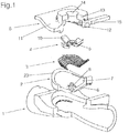
- FIG. 1 shows an exploded view of a diaphragm valve.
- the membrane valve holds a housing part 1, a membrane 2, a pressure distribution element 3, a pressure piece 4 and a hood. 5
- the membrane 2 is formed integrally from a polymeric material and has a flat region 6, to which an edge 7 connects.
- the flat area 6 is formed curved downward.
- the edge 7 extends in view of the drawing in a vertical upward direction.
- the flat area 6 is plate-shaped.
- the edge 7 is formed like a bead.
- the edge 7 of the membrane 2 protrudes upward in the vertical direction and has on its upper side a circumferential end face 23.
- the end face 23 is curved.
- the end face 23 of the edge 7 of the membrane 2 is not in a horizontal plane but is curved in the vertical direction.
- the curvature of the end face 23 has its lowest point in the area of the membrane web or of the membrane weir and then rises on both sides, so that in the entry region the end face 23 of the edge 7 of the membrane 2 has the highest elevation, then steadily decreases as far as the valve seat or the bridge or the weir and then rises again to the outlet and then increases again to the same height.
- the curvature of the end face 23 of the edge 7 of the membrane 2 thus runs parallel to the flow direction.
- the membrane 2 is designed so that it prevails in the closed position, the lowest voltage in the material of the membrane 2. When opening the valve, the membrane 2 is deformed and the tension in the membrane material increases.
- a form-fitting element is embedded, which is in communication with a drive, not shown, for the deformation of the membrane 2.
- the element 8 in the exemplary embodiment is a membrane screw.
- the element 8 is connected to a pressure piece 4 in connection.
- the pressure piece 4 can within the Hood to be moved in the vertical direction by means of a drive, not shown.
- the pressure distribution element 3 distributes the pressure exerted by the pressure piece 4 on the flat area 6 of the membrane. 2
- the pressure distribution element 3 is formed in the embodiment as a support spiral.
- the pressure piece 4 has an inner opening 9 for connection to a drive. Outwardly four arms 10 extend, so that the pressure piece 4 is formed cross-shaped in plan view.
- the hood 5 has a flat area 11, which is formed curved downward. Down a circumferential elevation 12 extends.
- the hood 5 has a hollow cylindrical neck 13, with a circular opening 14 for drive elements, not shown, such as a spindle.
- the hood 5 has a cavity 15 in which the pressure piece 4 is arranged displaceably in the vertical direction. In this case, the pressure piece 4 is guided by delimiting walls of the cavity 15 of the hood 5.
- FIG. 2 shows a side view of the hood 5. From walls of the hood 5 a chamber for the membrane 2 is limited.
- the peripheral elevation 12 and / or the area 11 of the hood are curved and arch in an arc to the axis 16 downwards.
- the elevation 12 and the area 11 have the shape of a mirror-symmetrical to the axis 16 formed bow.
- a lateral wall of the curved chambering for the membrane 2 is formed. From the area 11 of the hood, an upper wall of the chamber is formed.
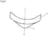
- FIG. 3 shows a side view of the membrane 2.
- the edge 7 of the membrane 2 is formed banana-shaped curved downward.
- the edge 7 of the membrane 2 forms a curved arc which is mirror-symmetrical to the axis 16.
- the plate-shaped area 6 of the membrane 2 is curved downward, mirror-symmetrical to the axis 16 formed.
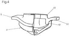
- FIG. 4 shows that the elevation 12 of the hood 5 forms a laterally delimiting wall for the membrane 2.
- the area 11 of the hood 5 forms a downwardly bounding wall of the chambering.
- FIG. 5 shows a perspective view of the housing part 1 from above, with a quarter has been omitted for partial sectional view.
- the housing part 1 is integrally formed, preferably made of a metallic material. It comprises a hollow cone-shaped inlet area 17, through which the medium flows, and a hollow cone-shaped outlet area 18, through which the medium flows.
- the input region 17 and / or the output region 18 preferably have connections for connection to other system components, for example pipelines.
- the housing part 1 has a weir or a web 19.
- the weir or the web 19 serves as a seat for a, preferably designed as a sealing lip region of the membrane. 2
- the weir or web 19 is preferably a survey formed transversely to the direction of flow.
- the lower housing part 1 of the diaphragm valve comprises a cuboid-shaped region 20, which can carry the hood 5 or not shown Fastening elements, such as screws, can be connected to the hood 5.
- the housing part 1 has a support surface 21, which is formed in an oval shape with a curvature. In the axial direction, the curvature at the height of the weir or the web 19 at its lowest point.
- the circumferential bearing surface 21 is formed obliquely.
- the support surface 21 is circumferential and mirror-symmetrical to the axis sixteenth
- FIG. 6 shows the chamber 22 formed by the housing part 1 and the hood 5 for the membrane 2.
- the membrane 2 is in FIG. 6 not shown deliberately to illustrate the cavity 22 shown as a cavity.
- the chamber 22 is formed as a cavity for receiving the edge 7 of the membrane 2. According to the invention, the chamber 22 is curved so that it does not lie in a horizontal plane, but is curved downwards.
- FIG. 7 shows a perspective view of the diaphragm valve with a quarter recess for partial sectional view.
- the membrane 2 serves as shut-off for sealing separation of rooms.
- the deformation of the membrane 2 can be enabled or disabled via a drive of a flow between the input area 17 and the output area 18 or it can be metered depending on the valve position, a medium, so that the diaphragm valve can be used either as a pure control valve with on / delivery is or as a control valve for controlling or dosing a medium.
- the membrane 2 additionally serves to seal the valve out to the atmosphere.
- the membrane 2 is clamped in the chamber 22 between the housing part 1 and the hood 5.
Landscapes
- Engineering & Computer Science (AREA)
- General Engineering & Computer Science (AREA)
- Mechanical Engineering (AREA)
- Fluid-Driven Valves (AREA)
Abstract
Description
- Die Erfindung betrifft ein Ventil mit einer Membran, die einen Rand aufweist, der in einer Kammerung angeordnet ist, die von einem Gehäuseteil und einer Haube gebildet wird.
- Membranventile können zur Dosierung von unterschiedlichen Fluiden eingesetzt werden, beispielsweise von Gasen, Dämpfen oder Flüssigkeiten. Beispielsweise können Membranventile eingesetzt werden, um hochviskose bzw. sehr stark haftfähige Medien zu dosieren bzw. zu verteilen. Bei Membranventilen wird dabei wirksam eine Ablagerung und somit auch eine Kontamination verhindert. Ventile auf Basis des Membranprinzips sind die totraumärmsten Dosierarmaturen. Neben dem sehr geringen Totraumvolumen sind Membranventile zudem entleerungsoptimiert konstruiert, sodass eine rückstandsfreie Entfernung des Mediums ermöglicht wird.
- Dies ist insbesondere bei pharmazeutischen Anlagen und Fertigungsprozessen von großer Bedeutung, da diese den hohen Ansprüchen einer strengen Validierung unterliegen, mit dem Ziel, eine gleichbleibende und reproduzierbare Qualität zu gewährleisten. Aus diesen Ansprüchen resultiert die Notwendigkeit, verschiedene Prozesse innerhalb einer Anlage fahren zu können. Neben dem eigentlichen Produktionsprozess sind dies in der Regel die Reinigung, Desinfektion und Sterilisation der Anlage. Membranventile haben sich aufgrund ihrer vorteilhaften Konstruktionsmerkmale als bevorzugte Armatur in der sterilen Prozesstechnik etabliert.
- Die eingesetzten Membranen bilden bewegliche, dichtende Wände, die zwei Räume mit in der Regel unterschiedlichen Medien (Gase, Flüssigkeiten) und häufig auch unterschiedlichen Druckverhältnissen voneinander trennen.
- Ein wichtiges Qualitätsmerkmal einer Membran ist deren Beweglichkeit, das heißt die Fähigkeit senkrecht zur Einspannfläche (Membranfläche) einen Hub auszuführen, der mechanisch angetrieben bedingt sein kann. Weiterhin ist die Beständigkeit der Membran von Bedeutung, insbesondere wenn aggressive Medien gefördert werden.
- Die Bewegungsfähigkeit und Beständigkeit einer Membran hängt im Wesentlichen vom Werkstoff ab, aus dem die Membran besteht. Als Grundwerkstoffe für Membranen werden hauptsächlich Elastomere verwendet, die zur Erzielung einer höheren Festigkeit mit Gewebeeinlagen verstärkt werden können. Als Elastomere haben sich Membranen mit Ethylen-Propylen-Dien-Kautschuk (EPDM) bewährt. Bei Ethylen-Propylen-Dien-Kautschuk (EPDM) handelt es sich um terpolymere Elastomere (Gummi) und somit um synthetische Kautschuke. Das Material zeichnet sich durch eine hohe Elastizität und gute chemische Beständigkeit aus.
- In der
DE 195 05 747 A1 wird ein Membranventil beschrieben, welches aus einem Gehäuse besteht, das ein Gehäuseoberteil und ein Gehäuseunterteil aufweist. Zwischen den beiden Gehäuseteilen ist eine Membran eingespannt, die einen Randwulst besitzt. Mithilfe einer außerhalb des Randwulstes gelegenen Verschraubung ist die Membran in einer Kammer eingespannt, die durch das Gehäuseoberteil und das Gehäuseunterteil gebildet wird. An den Randwulst ist ein außenliegender lappenartiger Fortsatz angeformt. Der lappenartige Fortsatz ist zwischen den entsprechenden Stirnflächen des Gehäuseoberteils und des Gehäuseunterteils angeordnet. - Der Einspannbereich einer Ventilmembran ist besonderen Anforderungen unterworfen. In erster Linie dient er der Halterung der Membran, deren Randbereich während des Schließens und in der Schließstellung einen radial nach innen gerichteten Zug ausgesetzt ist. Falls keine zusätzliche Abdichtung zwischen dem Unterteil und dem Oberteil des Gehäuses vorgesehen wird, kann der zwischen den Gehäuseteilen eingespannte Rand auch auf die Aufgabe der ruhenden Abdichtung übernehmen.
- Die auf den Einspannbereich der Membran ausgeübte Dauerbeanspruchung führt, vor allem bei einem flachen Membranrand, oftmals zu einer gestaltlichen Veränderung, die schließlich zu einer Undichtigkeit des Gehäuses im betroffenen Bereich führen kann. Ein rechtzeitiges Nachspannen der den Membranrand beaufschlagenden Verschraubung vermag zwar den Zeitpunkt zu verschieben, an dem eine solche Undichtigkeit auftritt, sie kann den hierfür ursächlichen Prozess aber nicht aufhalten.
- Bei Membranen, die einen zwischen den Gehäuseteilen eingespannten Randwulst besitzen, ist die geschilderte Problematik nicht oder nur im geringen Maße gegeben. Die auf den Randwulst ausgeübten Flächenpressung muss nicht so hoch sein wie bei einem flachen Rand, da der großräumige Wulst sich der ihm aufnehmenden Kammer anpasst, sodass eine gute Abdichtung sichergestellt ist. Die Kammerung des Einspannbereiches stellt eine dauerhafte Halterung sicher.
- Die an sich vorteilhafte Kammerung des Randwulstes birgt jedoch ein Problem in sich, das seine Ursache in einer nicht auszuschließenden unsachgemäßen Montage oder Wartung hat. Wird nämlich das von dem Hersteller eines solchen Membranventils vorgeschriebene Anzugsdrehmoment der Verschraubung um ein erhebliches Maß überschritten, so erfolgt eine radial nach innen gerichtete Verdrängung eines Teils des Membranmaterials des Randwulstes. An der rundum verlaufenden die Kammer begrenzenden Engstelle, die durch die beiden Gehäuseteile gebildet wird, ergibt sich so eine Materialanhäufung, die vor allem während der Membranbetätigung zu Spannungen in diesem und im benachbarten Membranbereich führt. Diese Spannungen können zu einem Einreißen der Membranoberfläche und zumindest bei Membranen ohne Faserverstärkung schließlich zu einem Membranbruch führen.
- Um ein über ein vorgeschriebenes Maß hinausgehendes Anziehen der Verschraubung zu vermeiden, könnten der Randwulst, die diesen aufnehmende Kammer und die Stirnflächen von Gehäuseunter- und -oberteil so gestaltet und bemessen werden, dass die maximal zulässige Pressung des Randwulstes erreicht wäre, wenn die Stirnflächen der Gehäuseteile zur Anlage aneinander kämen. Dies würde aber wegen der notwendigen Präzision einen hohen Aufwand bei der Fertigung der Membranen und der Gehäuseteile und möglicherweise zusätzlicher Anpassungsarbeiten notwendig machen.
In derDE 23 25 814 wird ein Ventil mit einer Membran beschrieben. Zwischen einem Gehäuseteil und einer Haube ist die Membran eingespannt. Die Betätigung der an einem Druckstück befestigten Membran erfolgt über eine Spindel mittels eines Handrades. Die Membran ist mit einem Verstärkungsgewebe ausgestattet. Sie hat an ihrem Rand einen Befestigungswulst, der in einer durch das Gehäuseteil und die Ventilhaube gebildeten Kammer gehaltert wird. - Bei den auf dem Markt befindlichen Membranventilen unterscheidet man Membranventile mit Steg und Membranventile mit freiem Durchgang. Membranventile mit Steg werden hauptsächlich zur Förderung von Fluiden eingesetzt, die nicht feststoffhaltig sind. Bei dieser Variante weist das Membranventil eine flache Membran auf, die eine lange Lebensdauer auch bei hohen Schaltzyklen gewährleistet. Weiterhin gibt es für Membranventile mit Steg ein großes Spektrum an einsetzbaren Werkstoffen. Zudem sind solche Membranventile mit Steg auch für höhere Drücke geeignet aufgrund der Abstützung der Membran mit einer Spirale.
- Dagegen sind Membranventile mit freiem Durchgang auch für feststoffhaltige Medien einsetzbar, da kein Steg als Erhöhung in der Rohrleitung vorhanden ist und somit die Abrasionsgefahr deutlich geringer ist. Solche Membranventile ohne Steg, die einen freien Durchgang aufweisen, können beispielsweise auch für stark feststoffhaltige Medien eingesetzt werden, wie sie beispielsweise beim Abtransportieren von Gestein mittels Wasser vorkommen, zum Beispiel beim Bohren in Erdschichten. Nachteile solcher Ventile mit freiem Durchgang sind die geringe Haltbarkeit der Membran, die durch die starke Verformung beim Öffnen und Schließen auftritt. Weiterhin weisen solche Ventile mit freiem Durchgang, also ohne einen durch die Rohrleitung hervorragenden Steg eine geringere Vielfalt bei der Werkstoffauswahl auf. Zudem besitzen solche Ventile eine schlechtere Druckbelastbarkeit aufgrund der mangelnden Abstützung der Membran.
- Aufgabe der Erfindung ist es, ein Membranventil anzugeben, das eine möglichst geringe Abrasion auch bei Förderung von feststoffhaltigen Medien aufweist. Gleichzeitig soll sich das Ventil durch eine möglichst geringe Belastung des Membranventils im Betrieb auszeichnen, sodass sich die Membran durch eine verhältnismäßig hohe Lebensdauer auszeichnet. Weiterhin soll eine zuverlässige Abdichtung des Ventils gewährleistet sein, sodass kein Medium austritt. Das Ventil soll sich durch geringe Strömungsverluste bzw. Druckverluste bei der Förderung und somit durch eine hohe Leistungsfähigkeit auszeichnen. Weiterhin soll das Membranventil möglichst preiswert herzustellen sein und einen flexiblen Einsatz bei unterschiedlichen Anwendungen gewährleisten.
- Diese Aufgabe wird erfindungsgemäß durch ein Ventil mit den Merkmalen des Anspruchs 1 gelöst. Bevorzugte Varianten sind den Unteransprüchen, der Beschreibung und den Zeichnungen zu entnehmen.
- Erfindungsgemäß ist die Kammerung, in der die Membran angeordnet ist, und/oder der Rand der Membran gewölbt ausgebildet. Bei herkömmlichen gekammerten Membranventilen nach dem Stand der Technik ist die Membran zwischen einem Gehäuseteil und einer Haube in einem Raum eingespannt, der in einer horizontalen Ebene ausgebildet ist. Dagegen ist die Kammerung des erfindungsgemäßen Ventils gewölbt ausgebildet und befindet sich nicht in einer horizontalen Ebene, sondern ist nach unten gekrümmt.
- Während bei herkömmlichen Membranventilen der Bereich, in dem die Membran aufliegt, flach ausgebildet ist, weist das erfindungsgemäße Ventil einen gebogenen Bereich auf, in dem die Membran aufliegt. Diese Biegung ermöglicht zum einen verhältnismäßig freien Durchgang und gleichzeitig einen großen Membranhub. Weiterhin wird eine zuverlässige Abdichtung des Ventils durch die Kammerung gewährleistet und die Membran weist eine ausreichende Abstützung auf.
- Bei einer besonders vorteilhaften Ausführung der Erfindung weist die Haube eine umlaufende Erhebung auf, die gewölbt ausgebildet ist. Bei der Erhebung handelt es sich um einen nach unten ragenden Vorsprung, der vorzugsweise eine seitliche Wandung für die Kammerung der Membran bildet. Der Rand der Membran kann über diese Erhebung gestülpt werden. Dadurch ragt die umlaufende Erhebung in einen von der Membran umschlossenen Hohlraum hinein. Bei einer Variante der Erfindung ist die Erhebung oval umlaufend.
- Weiterhin erweist es sich als günstig, wenn der Rand der Membran gewölbt ausgebildet ist. Während bei herkömmlichen gekammerten Membranen die Membranen einen Wulst bzw. Rand aufweisen, der auf einer Ebene liegt, weist das erfindungsgemäße Membranventil eine Membran auf, deren Rand gewölbt ausgebildet ist. Vorzugsweise hat die Wölbung im Bereich des Membransteges bzw. des Membranwehrs ihren tiefsten Punkt und steigt dann zu beiden Seiten hin an, sodass im Eintrittsbereich der Rand der Membran die höchste Erhebung hat, dann stetig abnimmt bis zu dem Ventilsitz bzw. dem Steg oder dem Wehr und dann wieder zum Austritt hin ansteigt und dann wieder auf die gleiche Höhe zunimmt.
- Der Rand der Membran ragt vorzugsweise in vertikaler Richtung nach oben und weist auf seiner Oberseite eine umlaufende Stirnfläche auf, die bei einer bevorzugten Variante der Erfindung gewölbt ausgebildet ist. Somit liegt die Stirnfläche des Randes der Membran nicht in einer horizontalen Ebene sondern ist in vertikaler Richtung gekrümmt. Die Wölbung der Stirnseite des Randes der Membran verläuft parallel zur Fließrichtung.
- Zudem erweist es sich als günstig, wenn die Haube einen flächigen Bereich aufweist, der gewölbt ausgebildet ist. Dieser flächige Bereich der Haube kann eine obere Begrenzung der Kammerung bilden. Der flächige Bereich kann als ein seitlich hervorstehender Rand der Haube ausgebildet sein, ähnlich wie die Krempe bei einem Hut.
- Bei einer Variante der Erfindung weist das Gehäuseteil eine seitliche Wandfläche auf, deren Rand gewölbt ausgebildet ist und auch einen Teil der Kammerung für die Membran bilden kann.
- Ergänzend oder alternativ kann das Gehäuseteil eine Auflagefläche für die Membran aufweisen, die gewölbt ausgebildet ist. Bei einer Variante der Erfindung ist diese Auflagefläche schräg ausgebildet.
- Vorzugsweise weist das Ventil ein Druckstück zur Verformung der Membran auf.
- Bei einer Variante der Erfindung umfasst das Ventil ein Druckverteilungselement, das vorzugsweise spiral- oder ringförmig ausgebildet ist.
- Weitere Merkmale und Vorteile der Erfindung ergeben sich aus der Beschreibung eines Ausführungsbeispieles anhand von Zeichnungen und aus den Zeichnungen selbst.
- Dabei zeigt:
- Figur 1
- eine perspektivische Explosionszeichnung eines Membranventils,
- Figur 2
- eine seitliche Ansicht einer Haube des Membranventils,
- Figur 3
- eine seitliche Ansicht einer Membran des Membranventils,
- Figur 4
- eine perspektivische Ansicht einer Haube des Membranventils und Membran,
- Figur 5
- eine perspektivische Ansicht eines Gehäuseteils des Membranventils,
- Figur 6
- die von einer Haube und einem Gehäuseteil gebildete Kammerung für die Membran des Membranventils,
- Figur 7
- eine perspektivische Darstellung mit geöffneten Viertel zur Teilschnittdarstellung des Membranventils.
-
Figur 1 zeigt eine Explosionszeichnung eines Membranventils. Das Membranventil fasst ein Gehäuseteil 1, eine Membran 2, ein Druckverteilungselement 3, ein Druckstück 4 und eine Haube 5. - Die Membran 2 ist einstückig aus einem polymeren Material ausgebildet und weist einen flächigen Bereich 6 auf, an den sich ein Rand 7 anschließt. Der flächige Bereich 6 ist nach unten gewölbt ausgebildet. Der Rand 7 erstreckt sich mit Blick auf die Zeichnung in vertikaler Richtung nach oben. Der flächige Bereich 6 ist tellerförmig. Der Rand 7 ist wulstartig ausgebildet.
- Der Rand 7 der Membran 2 ragt in vertikaler Richtung nach oben und weist auf seiner Oberseite eine umlaufende Stirnfläche 23 auf. Die Stirnfläche 23 ist gewölbt ausgebildet. Somit liegt die Stirnfläche 23 des Randes 7 der Membran 2 nicht in einer horizontalen Ebene sondern ist in vertikaler Richtung gekrümmt. Die Wölbung der Stirnfläche 23 weist im Bereich des Membransteges bzw. des Membranwehrs ihren tiefsten Punkt und steigt dann zu beiden Seiten hin an, sodass im Eintrittsbereich die Stirnfläche 23 des Randes 7 der Membran 2 die höchste Erhebung hat, dann stetig abnimmt bis zu dem Ventilsitz bzw. dem Steg oder dem Wehr und dann wieder zum Austritt hin ansteigt und dann wieder auf die gleiche Höhe zunimmt. Die Wölbung der Stirnfläche 23 des Randes 7 der Membran 2 verläuft somit parallel zur Strömungsrichtung.
- Im Ausführungsbeispiel ist die Membran 2 so ausgebildet, dass sie in geschlossener Stellung die geringste Spannung im Material der Membran 2 herrscht. Bei einer Öffnung des Ventils wird die Membran 2 verformt und die Spannung im Membranmaterial steigt an.
- In der Membran 2 ist formschlüssig ein Element eingebettet, das mit einem nicht dargestellten Antrieb zur Verformung der Membran 2 in Verbindung steht. Bei dem Element 8 handelt es sich im Ausführungsbeispiel um eine Membranschraube. Das Element 8 steht mit einem Druckstück 4 in Verbindung. Das Druckstück 4 kann innerhalb der Haube in vertikaler Richtung mittels eines nicht dargestellten Antriebs verschoben werden. Das Druckverteilungselement 3 verteilt den vom Druckstück 4 ausgeübten Druck auf den flächigen Bereich 6 der Membran 2.
- Das Druckverteilungselement 3 ist im Ausführungsbeispiel als Abstützspirale ausgebildet.
- Das Druckstück 4 weist eine innere Öffnung 9 zur Verbindung mit einem Antrieb auf. Nach außen erstrecken sich vier Ausleger 10, sodass das Druckstück 4 in der Draufsicht kreuzförmig ausgebildet ist.
- Die Haube 5 weist einen flächigen Bereich 11 auf, der nach unten gewölbt ausgebildet ist. Nach unten erstreckt sich eine umlaufende Erhebung 12.
- Mittig weist die Haube 5 einen hohlzylinderförmig ausgebildeten Hals 13 auf, mit einer kreisförmigen Öffnung 14 für nicht dargestellte Antriebselemente, wie beispielsweise eine Spindel.
- Die Haube 5 weist einen Hohlraum 15 auf, in dem das Druckstück 4 in vertikaler Richtung verschieblich angeordnet ist. Dabei wird das Druckstück 4 von begrenzenden Wänden des Hohlraums 15 der Haube 5 geführt.
-
Figur 2 zeigt eine seitliche Ansicht der Haube 5. Von Wandungen der Haube 5 wird eine Kammerung für die Membran 2 begrenzt. Um die erfindungsgemäß gewölbte Kammerung auszubilden, sind die umlaufende Erhebung 12 und/oder der flächige Bereich 11 der Haube gekrümmt ausgeführt und wölben sich in einem Bogen zur Achse 16 nach unten. Die Erhebung 12 und der flächige Bereich 11 weisen die Form eines spiegelsymmetrisch zur Achse 16 ausgebildeten Bogens auf. - Von der Erhebung 12 wird eine seitliche Wandung der gekrümmten Kammerung für die Membran 2 gebildet. Von dem flächigen Bereich 11 der Haube wird eine obere Wandung der Kammerung gebildet.
-
Figur 3 zeigt eine seitliche Ansicht der Membran 2. Der Rand 7 der Membran 2 ist bananenförmig nach unten gekrümmt ausgebildet. Der Rand 7 der Membran 2 bildet einen gewölbten Bogen, der spiegelsymmetrisch zur Achse 16 ausgebildet ist. Auch der tellerförmig ausgebildete flächige Bereich 6 der Membran 2 ist nach unten gewölbt, spiegelsymmetrisch zur Achse 16 ausgebildet. -
Figur 4 zeigt, dass die Erhebung 12 der Haube 5 eine seitlich begrenzende Wandung für die Membran 2 bildet. Der flächige Bereich 11 der Haube 5 bildet eine nach unten begrenzende Wandung der Kammerung. -
Figur 5 zeigt eine perspektivische Ansicht des Gehäuseteils 1 von oben, wobei ein Viertel zur Teilschnittdarstellung weggelassen wurde. - Das Gehäuseteil 1 ist einstückig, vorzugsweise aus einem metallischen Werkstoff, ausgebildet. Es umfasst einen hohlkegelförmigen ausgebildeten Eingangsbereich 17, durch den das Medium einströmt und einen hohlkegelförmig ausgebildeten Ausgangsbereich 18, durch den das Medium ausströmt. Der Eingangsbereich 17 und/oder der Ausgangsbereich 18 weisen vorzugsweise Anschlüsse zur Verbindung mit anderen Anlageteilen, beispielsweise Rohrleitungen, auf.
- Mittig im Inneren weist das Gehäuseteil 1 ein Wehr bzw. einen Steg 19 auf. Das Wehr bzw. der Steg 19 dient als Sitzfläche für einen, vorzugsweise als Dichtlippe ausgebildeten Bereich der Membran 2.
- Bei dem Wehr bzw. Steg 19 handelt es sich vorzugsweise um eine quer zur Strömungsrichtung ausgebildete Erhebung.
- Weiterhin umfasst das untere Gehäuseteil 1 des Membranventils einen quaderartig ausgebildeten Bereich 20, welcher die Haube 5 tragen kann bzw. über nicht dargestellte Befestigungselemente, wie zum Beispiel Schrauben, mit der Haube 5 verbunden werden kann. Der Bereich 20 des Gehäuseteils 1 bildet gemeinsam mit der Haube 5 eine Kammerung für die Membran 2.
- Weiterhin weist das Gehäuseteil 1 eine Auflagefläche 21 auf, die ovalförmig umlaufend mit einer Wölbung ausgebildet ist. In axialer Richtung weist die Wölbung auf der Höhe des Wehres bzw. des Steges 19 ihren tiefsten Punkt auf. Die umlaufende Auflagefläche 21 ist schräg ausgebildet. Die Auflagefläche 21 ist umlaufend und spiegelsymmetrisch zur Achse 16.
-
Figur 6 zeigt die von dem Gehäuseteil 1 und der Haube 5 gebildete Kammerung 22 für die Membran 2. Die Membran 2 ist inFigur 6 bewusst nicht dargestellt, um die als Hohlraum dargestellte Kammerung 22 zu verdeutlichen. - Die Kammerung 22 ist als Hohlraum zur Aufnahme des Randes 7 der Membran 2 ausgebildet. Erfindungsgemäß ist die Kammerung 22 gewölbt, sodass sie nicht in einer horizontalen Ebene liegt, sondern nach unten gekrümmt ausgebildet ist.
-
Figur 7 zeigt eine perspektivische Ansicht des Membranventils mit einer Viertelaussparung zur teilweisen Schnittdarstellung. Die Membran 2 dient als Absperrkörper zur dichtenden Trennung von Räumen. Im Ausführungsbeispiel kann die Verformung der Membran 2 über einen Antrieb einer Strömung zwischen dem Eingangsbereich 17 und dem Ausgangsbereich 18 freigegeben oder gesperrt werden bzw. es kann je nach Ventilstellung ein Medium dosiert werden, sodass das Membranventil entweder als reine Schaltarmatur mit Auf-/Zustellung einsetzbar ist oder als Stellarmatur zur Regelung bzw. Dosierung eines Mediums. - Die Membran 2 dient zusätzlich der Abdichtung des Ventils nach außen zur Atmosphäre hin. Dazu ist die Membran 2 in der Kammerung 22 zwischen dem Gehäuseteil 1 und der Haube 5 eingespannt.
Claims (10)
- Ventil mit einer Membran (2), die einen Rand (7) aufweist, der in einer Kammerung (22) angeordnet ist, die von einem Gehäuseteil (1) und einer Haube (5) gebildet wird, wobei das Ventil einen Steg (19) aufweist,
dadurch gekennzeichnet, dass
die Kammerung (22) gewölbt ausgebildet ist. - Ventil nach Anspruch 1, dadurch gekennzeichnet, dass die Haube (5) eine umlaufende Erhebung (12) aufweist, die gewölbt ausgebildet ist.
- Ventil nach Anspruch 1 oder 2, dadurch gekennzeichnet, dass der Rand (7) der Membran (2) gewölbt ausgebildet ist.
- Ventil nach einem der Ansprüche 1 bis 3, dadurch gekennzeichnet, dass die Haube (5) einen flächigen Bereich (11) aufweist, der gewölbt ausgebildet ist.
- Ventil nach einem der Ansprüche 1 bis 4, dadurch gekennzeichnet, dass das Gehäuseteil (1) eine seitliche Randfläche aufweist, die gewölbt ausgebildet ist.
- Ventil nach einem der Ansprüche 1 bis 5, dadurch gekennzeichnet, dass das Gehäuseteil (1) eine Auflagefläche (21) aufweist, die gewölbt ausgebildet ist.
- Ventil nach einem der Ansprüche 1 bis 6, dadurch gekennzeichnet, dass das Ventil ein Druckstück (4) aufweist.
- Ventil nach einem der Ansprüche 1 bis 7, dadurch gekennzeichnet, dass das Ventil ein Druckverteilungselement (3) aufweist, das vorzugsweise spiralförmig oder ringförmig ausgebildet ist.
- Ventil nach einem der Ansprüche 1 bis 8, dadurch gekennzeichnet, dass der Rand (7) der Membran (2) in vertikaler Richtung nach oben ragt und auf seiner Oberseite eine umlaufende Stirnfläche (23) aufweist, wobei die Stirnfläche (23) gewölbt ausgebildet ist.
- Ventil nach einem der Ansprüche 1 bis 9, dadurch gekennzeichnet, dass die Wölbung im Bereich eines Wehrs ihren tiefsten Punkt aufweist und vorzugsweise zur Strömungsrichtung hin und/oder entgegen der Strömungsrichtung ansteigt.
Applications Claiming Priority (1)
| Application Number | Priority Date | Filing Date | Title |
|---|---|---|---|
| DE102017103572 | 2017-02-22 |
Publications (2)
| Publication Number | Publication Date |
|---|---|
| EP3366961A1 true EP3366961A1 (de) | 2018-08-29 |
| EP3366961B1 EP3366961B1 (de) | 2020-11-18 |
Family
ID=60942908
Family Applications (1)
| Application Number | Title | Priority Date | Filing Date |
|---|---|---|---|
| EP18150573.6A Active EP3366961B1 (de) | 2017-02-22 | 2018-01-08 | Membranventil mit freiem durchgang |
Country Status (1)
| Country | Link |
|---|---|
| EP (1) | EP3366961B1 (de) |
Cited By (1)
| Publication number | Priority date | Publication date | Assignee | Title |
|---|---|---|---|---|
| DE102021129348A1 (de) | 2021-11-11 | 2023-05-11 | Sisto Armaturen S.A. | Flexibles Druckverteilungselement |
Families Citing this family (2)
| Publication number | Priority date | Publication date | Assignee | Title |
|---|---|---|---|---|
| DE102021129349A1 (de) | 2021-11-11 | 2023-05-11 | Sisto Armaturen S.A. | Bewegliches Druckstück |
| DE102021129940A1 (de) | 2021-11-17 | 2023-05-17 | Sisto Armaturen S.A. | Sekundärabdichtung |
Citations (11)
| Publication number | Priority date | Publication date | Assignee | Title |
|---|---|---|---|---|
| US1855991A (en) * | 1930-10-11 | 1932-04-26 | Saunders Inv S Ltd | Diaphragm valve |
| US2716017A (en) * | 1952-08-28 | 1955-08-23 | Grinnell Corp | Diaphragm valves |
| GB926129A (en) * | 1958-02-25 | 1963-05-15 | Leslie Sumner | Improvements relating to diaphragm valves |
| US3414235A (en) * | 1964-12-30 | 1968-12-03 | Henry Marie Joseph Georges Lumpp | Diaphragm carrying systems |
| DE1450575B1 (de) * | 1963-10-14 | 1969-09-04 | Grinnell Corp | Membranventil |
| FR2287633A1 (fr) * | 1974-10-08 | 1976-05-07 | Muguet Fernand | Vanne a membrane |
| US5279328A (en) * | 1993-01-19 | 1994-01-18 | Fluoroware, Inc. | Weir valve with adjustable bypass |
| DE19505747A1 (de) * | 1995-02-20 | 1996-08-22 | Sisto Armaturen Sa | Membranventil |
| US5632465A (en) * | 1990-10-29 | 1997-05-27 | Cordua; Paul M. | Valve assembly |
| US20060226392A1 (en) * | 2005-04-11 | 2006-10-12 | Gemu Gebruder Muller Apparatebau | Diaphragm valve |
| WO2015181709A1 (en) * | 2014-05-28 | 2015-12-03 | Alberto Lodolo | "hydraulic servo-actuated valve having a simplified assembly |
-
2018
- 2018-01-08 EP EP18150573.6A patent/EP3366961B1/de active Active
Patent Citations (11)
| Publication number | Priority date | Publication date | Assignee | Title |
|---|---|---|---|---|
| US1855991A (en) * | 1930-10-11 | 1932-04-26 | Saunders Inv S Ltd | Diaphragm valve |
| US2716017A (en) * | 1952-08-28 | 1955-08-23 | Grinnell Corp | Diaphragm valves |
| GB926129A (en) * | 1958-02-25 | 1963-05-15 | Leslie Sumner | Improvements relating to diaphragm valves |
| DE1450575B1 (de) * | 1963-10-14 | 1969-09-04 | Grinnell Corp | Membranventil |
| US3414235A (en) * | 1964-12-30 | 1968-12-03 | Henry Marie Joseph Georges Lumpp | Diaphragm carrying systems |
| FR2287633A1 (fr) * | 1974-10-08 | 1976-05-07 | Muguet Fernand | Vanne a membrane |
| US5632465A (en) * | 1990-10-29 | 1997-05-27 | Cordua; Paul M. | Valve assembly |
| US5279328A (en) * | 1993-01-19 | 1994-01-18 | Fluoroware, Inc. | Weir valve with adjustable bypass |
| DE19505747A1 (de) * | 1995-02-20 | 1996-08-22 | Sisto Armaturen Sa | Membranventil |
| US20060226392A1 (en) * | 2005-04-11 | 2006-10-12 | Gemu Gebruder Muller Apparatebau | Diaphragm valve |
| WO2015181709A1 (en) * | 2014-05-28 | 2015-12-03 | Alberto Lodolo | "hydraulic servo-actuated valve having a simplified assembly |
Cited By (2)
| Publication number | Priority date | Publication date | Assignee | Title |
|---|---|---|---|---|
| DE102021129348A1 (de) | 2021-11-11 | 2023-05-11 | Sisto Armaturen S.A. | Flexibles Druckverteilungselement |
| EP4180696A1 (de) * | 2021-11-11 | 2023-05-17 | SISTO Armaturen S.A. | Flexibles druckverteilungselement |
Also Published As
| Publication number | Publication date |
|---|---|
| EP3366961B1 (de) | 2020-11-18 |
Similar Documents
| Publication | Publication Date | Title |
|---|---|---|
| EP3324084B1 (de) | Membranventil | |
| WO2019034401A1 (de) | Dichtungsanordnung | |
| EP3366961B1 (de) | Membranventil mit freiem durchgang | |
| EP2527700A1 (de) | Ventil | |
| EP3029333A1 (de) | Axial geteilte pumpe | |
| DE102014004668A1 (de) | Ventil | |
| EP3029334A1 (de) | Axial geteilte pumpe | |
| EP3029332A1 (de) | Axial geteilte pumpe | |
| DE102014108379A1 (de) | Absperrvorrichtung | |
| EP1635094B1 (de) | Ventil | |
| DE102017213153A1 (de) | Doppelsitzventil für aseptische Produktleitungen | |
| DE102008031450A1 (de) | Pumpe | |
| DE102011119458B4 (de) | Zwischenflanschrückschlagklappenvorrichtung | |
| DE102016122661A1 (de) | Druckreduzierventil für flüssige und gasförmige Medien | |
| EP4184042A1 (de) | Membranventil mit einer sekundaerabdichtung | |
| WO1993022588A1 (de) | Manschettenverankerung | |
| EP1775503B1 (de) | Dichtungseinrichtung für ein Ventilgehäuse | |
| DE102013100794B3 (de) | Pumpenventil | |
| DE102012223281A1 (de) | Hochdruckdichtung für einen Kugelhahn und Kugelhahn | |
| EP2363606B1 (de) | Kompressorventil zum Steuern einer Kolbenmaschine | |
| DE2011435A1 (de) | ||
| WO2010149421A1 (de) | Ventilkörper | |
| DE19501356C2 (de) | An einem Behälter angeordnetes Ventil | |
| DE202015003689U1 (de) | Absperrventil und dessen Herstellung | |
| DE102021129349A1 (de) | Bewegliches Druckstück |
Legal Events
| Date | Code | Title | Description |
|---|---|---|---|
| PUAI | Public reference made under article 153(3) epc to a published international application that has entered the european phase |
Free format text: ORIGINAL CODE: 0009012 |
|
| STAA | Information on the status of an ep patent application or granted ep patent |
Free format text: STATUS: THE APPLICATION HAS BEEN PUBLISHED |
|
| AK | Designated contracting states |
Kind code of ref document: A1 Designated state(s): AL AT BE BG CH CY CZ DE DK EE ES FI FR GB GR HR HU IE IS IT LI LT LU LV MC MK MT NL NO PL PT RO RS SE SI SK SM TR |
|
| AX | Request for extension of the european patent |
Extension state: BA ME |
|
| STAA | Information on the status of an ep patent application or granted ep patent |
Free format text: STATUS: REQUEST FOR EXAMINATION WAS MADE |
|
| 17P | Request for examination filed |
Effective date: 20190226 |
|
| RBV | Designated contracting states (corrected) |
Designated state(s): AL AT BE BG CH CY CZ DE DK EE ES FI FR GB GR HR HU IE IS IT LI LT LU LV MC MK MT NL NO PL PT RO RS SE SI SK SM TR |
|
| STAA | Information on the status of an ep patent application or granted ep patent |
Free format text: STATUS: EXAMINATION IS IN PROGRESS |
|
| 17Q | First examination report despatched |
Effective date: 20190529 |
|
| GRAP | Despatch of communication of intention to grant a patent |
Free format text: ORIGINAL CODE: EPIDOSNIGR1 |
|
| STAA | Information on the status of an ep patent application or granted ep patent |
Free format text: STATUS: GRANT OF PATENT IS INTENDED |
|
| INTG | Intention to grant announced |
Effective date: 20200619 |
|
| GRAS | Grant fee paid |
Free format text: ORIGINAL CODE: EPIDOSNIGR3 |
|
| GRAA | (expected) grant |
Free format text: ORIGINAL CODE: 0009210 |
|
| STAA | Information on the status of an ep patent application or granted ep patent |
Free format text: STATUS: THE PATENT HAS BEEN GRANTED |
|
| AK | Designated contracting states |
Kind code of ref document: B1 Designated state(s): AL AT BE BG CH CY CZ DE DK EE ES FI FR GB GR HR HU IE IS IT LI LT LU LV MC MK MT NL NO PL PT RO RS SE SI SK SM TR |
|
| REG | Reference to a national code |
Ref country code: GB Ref legal event code: FG4D Free format text: NOT ENGLISH |
|
| REG | Reference to a national code |
Ref country code: CH Ref legal event code: EP |
|
| REG | Reference to a national code |
Ref country code: DE Ref legal event code: R096 Ref document number: 502018003005 Country of ref document: DE |
|
| REG | Reference to a national code |
Ref country code: IE Ref legal event code: FG4D Free format text: LANGUAGE OF EP DOCUMENT: GERMAN |
|
| REG | Reference to a national code |
Ref country code: AT Ref legal event code: REF Ref document number: 1336141 Country of ref document: AT Kind code of ref document: T Effective date: 20201215 |
|
| REG | Reference to a national code |
Ref country code: NL Ref legal event code: MP Effective date: 20201118 |
|
| PG25 | Lapsed in a contracting state [announced via postgrant information from national office to epo] |
Ref country code: FI Free format text: LAPSE BECAUSE OF FAILURE TO SUBMIT A TRANSLATION OF THE DESCRIPTION OR TO PAY THE FEE WITHIN THE PRESCRIBED TIME-LIMIT Effective date: 20201118 Ref country code: RS Free format text: LAPSE BECAUSE OF FAILURE TO SUBMIT A TRANSLATION OF THE DESCRIPTION OR TO PAY THE FEE WITHIN THE PRESCRIBED TIME-LIMIT Effective date: 20201118 Ref country code: PT Free format text: LAPSE BECAUSE OF FAILURE TO SUBMIT A TRANSLATION OF THE DESCRIPTION OR TO PAY THE FEE WITHIN THE PRESCRIBED TIME-LIMIT Effective date: 20210318 Ref country code: GR Free format text: LAPSE BECAUSE OF FAILURE TO SUBMIT A TRANSLATION OF THE DESCRIPTION OR TO PAY THE FEE WITHIN THE PRESCRIBED TIME-LIMIT Effective date: 20210219 Ref country code: NO Free format text: LAPSE BECAUSE OF FAILURE TO SUBMIT A TRANSLATION OF THE DESCRIPTION OR TO PAY THE FEE WITHIN THE PRESCRIBED TIME-LIMIT Effective date: 20210218 |
|
| PG25 | Lapsed in a contracting state [announced via postgrant information from national office to epo] |
Ref country code: BG Free format text: LAPSE BECAUSE OF FAILURE TO SUBMIT A TRANSLATION OF THE DESCRIPTION OR TO PAY THE FEE WITHIN THE PRESCRIBED TIME-LIMIT Effective date: 20210218 Ref country code: IS Free format text: LAPSE BECAUSE OF FAILURE TO SUBMIT A TRANSLATION OF THE DESCRIPTION OR TO PAY THE FEE WITHIN THE PRESCRIBED TIME-LIMIT Effective date: 20210318 Ref country code: LV Free format text: LAPSE BECAUSE OF FAILURE TO SUBMIT A TRANSLATION OF THE DESCRIPTION OR TO PAY THE FEE WITHIN THE PRESCRIBED TIME-LIMIT Effective date: 20201118 Ref country code: PL Free format text: LAPSE BECAUSE OF FAILURE TO SUBMIT A TRANSLATION OF THE DESCRIPTION OR TO PAY THE FEE WITHIN THE PRESCRIBED TIME-LIMIT Effective date: 20201118 Ref country code: SE Free format text: LAPSE BECAUSE OF FAILURE TO SUBMIT A TRANSLATION OF THE DESCRIPTION OR TO PAY THE FEE WITHIN THE PRESCRIBED TIME-LIMIT Effective date: 20201118 |
|
| REG | Reference to a national code |
Ref country code: LT Ref legal event code: MG9D |
|
| PG25 | Lapsed in a contracting state [announced via postgrant information from national office to epo] |
Ref country code: HR Free format text: LAPSE BECAUSE OF FAILURE TO SUBMIT A TRANSLATION OF THE DESCRIPTION OR TO PAY THE FEE WITHIN THE PRESCRIBED TIME-LIMIT Effective date: 20201118 |
|
| PG25 | Lapsed in a contracting state [announced via postgrant information from national office to epo] |
Ref country code: RO Free format text: LAPSE BECAUSE OF FAILURE TO SUBMIT A TRANSLATION OF THE DESCRIPTION OR TO PAY THE FEE WITHIN THE PRESCRIBED TIME-LIMIT Effective date: 20201118 Ref country code: SK Free format text: LAPSE BECAUSE OF FAILURE TO SUBMIT A TRANSLATION OF THE DESCRIPTION OR TO PAY THE FEE WITHIN THE PRESCRIBED TIME-LIMIT Effective date: 20201118 Ref country code: SM Free format text: LAPSE BECAUSE OF FAILURE TO SUBMIT A TRANSLATION OF THE DESCRIPTION OR TO PAY THE FEE WITHIN THE PRESCRIBED TIME-LIMIT Effective date: 20201118 Ref country code: LT Free format text: LAPSE BECAUSE OF FAILURE TO SUBMIT A TRANSLATION OF THE DESCRIPTION OR TO PAY THE FEE WITHIN THE PRESCRIBED TIME-LIMIT Effective date: 20201118 Ref country code: CZ Free format text: LAPSE BECAUSE OF FAILURE TO SUBMIT A TRANSLATION OF THE DESCRIPTION OR TO PAY THE FEE WITHIN THE PRESCRIBED TIME-LIMIT Effective date: 20201118 Ref country code: EE Free format text: LAPSE BECAUSE OF FAILURE TO SUBMIT A TRANSLATION OF THE DESCRIPTION OR TO PAY THE FEE WITHIN THE PRESCRIBED TIME-LIMIT Effective date: 20201118 |
|
| REG | Reference to a national code |
Ref country code: DE Ref legal event code: R097 Ref document number: 502018003005 Country of ref document: DE |
|
| PG25 | Lapsed in a contracting state [announced via postgrant information from national office to epo] |
Ref country code: DK Free format text: LAPSE BECAUSE OF FAILURE TO SUBMIT A TRANSLATION OF THE DESCRIPTION OR TO PAY THE FEE WITHIN THE PRESCRIBED TIME-LIMIT Effective date: 20201118 Ref country code: MC Free format text: LAPSE BECAUSE OF FAILURE TO SUBMIT A TRANSLATION OF THE DESCRIPTION OR TO PAY THE FEE WITHIN THE PRESCRIBED TIME-LIMIT Effective date: 20201118 |
|
| REG | Reference to a national code |
Ref country code: CH Ref legal event code: PL |
|
| PLBE | No opposition filed within time limit |
Free format text: ORIGINAL CODE: 0009261 |
|
| STAA | Information on the status of an ep patent application or granted ep patent |
Free format text: STATUS: NO OPPOSITION FILED WITHIN TIME LIMIT |
|
| PG25 | Lapsed in a contracting state [announced via postgrant information from national office to epo] |
Ref country code: LU Free format text: LAPSE BECAUSE OF NON-PAYMENT OF DUE FEES Effective date: 20210108 |
|
| REG | Reference to a national code |
Ref country code: BE Ref legal event code: MM Effective date: 20210131 |
|
| 26N | No opposition filed |
Effective date: 20210819 |
|
| PG25 | Lapsed in a contracting state [announced via postgrant information from national office to epo] |
Ref country code: NL Free format text: LAPSE BECAUSE OF FAILURE TO SUBMIT A TRANSLATION OF THE DESCRIPTION OR TO PAY THE FEE WITHIN THE PRESCRIBED TIME-LIMIT Effective date: 20201118 Ref country code: AL Free format text: LAPSE BECAUSE OF FAILURE TO SUBMIT A TRANSLATION OF THE DESCRIPTION OR TO PAY THE FEE WITHIN THE PRESCRIBED TIME-LIMIT Effective date: 20201118 Ref country code: IT Free format text: LAPSE BECAUSE OF FAILURE TO SUBMIT A TRANSLATION OF THE DESCRIPTION OR TO PAY THE FEE WITHIN THE PRESCRIBED TIME-LIMIT Effective date: 20201118 |
|
| PG25 | Lapsed in a contracting state [announced via postgrant information from national office to epo] |
Ref country code: CH Free format text: LAPSE BECAUSE OF NON-PAYMENT OF DUE FEES Effective date: 20210131 Ref country code: SI Free format text: LAPSE BECAUSE OF FAILURE TO SUBMIT A TRANSLATION OF THE DESCRIPTION OR TO PAY THE FEE WITHIN THE PRESCRIBED TIME-LIMIT Effective date: 20201118 Ref country code: LI Free format text: LAPSE BECAUSE OF NON-PAYMENT OF DUE FEES Effective date: 20210131 |
|
| PG25 | Lapsed in a contracting state [announced via postgrant information from national office to epo] |
Ref country code: ES Free format text: LAPSE BECAUSE OF FAILURE TO SUBMIT A TRANSLATION OF THE DESCRIPTION OR TO PAY THE FEE WITHIN THE PRESCRIBED TIME-LIMIT Effective date: 20201118 Ref country code: IE Free format text: LAPSE BECAUSE OF NON-PAYMENT OF DUE FEES Effective date: 20210108 |
|
| PG25 | Lapsed in a contracting state [announced via postgrant information from national office to epo] |
Ref country code: IS Free format text: LAPSE BECAUSE OF FAILURE TO SUBMIT A TRANSLATION OF THE DESCRIPTION OR TO PAY THE FEE WITHIN THE PRESCRIBED TIME-LIMIT Effective date: 20210318 |
|
| PG25 | Lapsed in a contracting state [announced via postgrant information from national office to epo] |
Ref country code: BE Free format text: LAPSE BECAUSE OF NON-PAYMENT OF DUE FEES Effective date: 20210131 |
|
| PG25 | Lapsed in a contracting state [announced via postgrant information from national office to epo] |
Ref country code: CY Free format text: LAPSE BECAUSE OF FAILURE TO SUBMIT A TRANSLATION OF THE DESCRIPTION OR TO PAY THE FEE WITHIN THE PRESCRIBED TIME-LIMIT Effective date: 20201118 |
|
| PG25 | Lapsed in a contracting state [announced via postgrant information from national office to epo] |
Ref country code: HU Free format text: LAPSE BECAUSE OF FAILURE TO SUBMIT A TRANSLATION OF THE DESCRIPTION OR TO PAY THE FEE WITHIN THE PRESCRIBED TIME-LIMIT; INVALID AB INITIO Effective date: 20180108 |
|
| P01 | Opt-out of the competence of the unified patent court (upc) registered |
Effective date: 20230713 |
|
| REG | Reference to a national code |
Ref country code: AT Ref legal event code: MM01 Ref document number: 1336141 Country of ref document: AT Kind code of ref document: T Effective date: 20230108 |
|
| PG25 | Lapsed in a contracting state [announced via postgrant information from national office to epo] |
Ref country code: AT Free format text: LAPSE BECAUSE OF NON-PAYMENT OF DUE FEES Effective date: 20230108 |
|
| PG25 | Lapsed in a contracting state [announced via postgrant information from national office to epo] |
Ref country code: MK Free format text: LAPSE BECAUSE OF FAILURE TO SUBMIT A TRANSLATION OF THE DESCRIPTION OR TO PAY THE FEE WITHIN THE PRESCRIBED TIME-LIMIT Effective date: 20201118 Ref country code: AT Free format text: LAPSE BECAUSE OF NON-PAYMENT OF DUE FEES Effective date: 20230108 |
|
| PG25 | Lapsed in a contracting state [announced via postgrant information from national office to epo] |
Ref country code: MT Free format text: LAPSE BECAUSE OF FAILURE TO SUBMIT A TRANSLATION OF THE DESCRIPTION OR TO PAY THE FEE WITHIN THE PRESCRIBED TIME-LIMIT Effective date: 20201118 |
|
| PG25 | Lapsed in a contracting state [announced via postgrant information from national office to epo] |
Ref country code: TR Free format text: LAPSE BECAUSE OF FAILURE TO SUBMIT A TRANSLATION OF THE DESCRIPTION OR TO PAY THE FEE WITHIN THE PRESCRIBED TIME-LIMIT Effective date: 20201118 |
|
| PGFP | Annual fee paid to national office [announced via postgrant information from national office to epo] |
Ref country code: GB Payment date: 20260121 Year of fee payment: 9 |
|
| PGFP | Annual fee paid to national office [announced via postgrant information from national office to epo] |
Ref country code: DE Payment date: 20260129 Year of fee payment: 9 |
|
| PGFP | Annual fee paid to national office [announced via postgrant information from national office to epo] |
Ref country code: AT Payment date: 20260410 Year of fee payment: 5 |
|
| PGFP | Annual fee paid to national office [announced via postgrant information from national office to epo] |
Ref country code: FR Payment date: 20260125 Year of fee payment: 9 |