EP3366869A1 - Système de commande pour parcs à voitures automatiques - Google Patents
Système de commande pour parcs à voitures automatiques Download PDFInfo
- Publication number
- EP3366869A1 EP3366869A1 EP18157874.1A EP18157874A EP3366869A1 EP 3366869 A1 EP3366869 A1 EP 3366869A1 EP 18157874 A EP18157874 A EP 18157874A EP 3366869 A1 EP3366869 A1 EP 3366869A1
- Authority
- EP
- European Patent Office
- Prior art keywords
- parking
- processing unit
- parking garage
- garage
- data processing
- Prior art date
- Legal status (The legal status is an assumption and is not a legal conclusion. Google has not performed a legal analysis and makes no representation as to the accuracy of the status listed.)
- Pending
Links
- 238000012545 processing Methods 0.000 claims abstract description 74
- 238000004891 communication Methods 0.000 claims abstract description 34
- 238000000034 method Methods 0.000 claims abstract description 20
- 238000012946 outsourcing Methods 0.000 claims abstract description 9
- 238000013459 approach Methods 0.000 claims abstract description 6
- 238000005096 rolling process Methods 0.000 description 32
- 238000012546 transfer Methods 0.000 description 26
- 238000011161 development Methods 0.000 description 9
- 238000007726 management method Methods 0.000 description 5
- 238000010586 diagram Methods 0.000 description 4
- 238000009434 installation Methods 0.000 description 4
- 238000010276 construction Methods 0.000 description 3
- 238000013461 design Methods 0.000 description 2
- 238000006073 displacement reaction Methods 0.000 description 2
- 238000005265 energy consumption Methods 0.000 description 2
- 239000003344 environmental pollutant Substances 0.000 description 2
- 238000012544 monitoring process Methods 0.000 description 2
- 231100000719 pollutant Toxicity 0.000 description 2
- 230000008878 coupling Effects 0.000 description 1
- 238000010168 coupling process Methods 0.000 description 1
- 238000005859 coupling reaction Methods 0.000 description 1
- 230000001419 dependent effect Effects 0.000 description 1
- 238000012549 training Methods 0.000 description 1
- 230000007704 transition Effects 0.000 description 1
Images


Classifications
-
- G—PHYSICS
- G08—SIGNALLING
- G08G—TRAFFIC CONTROL SYSTEMS
- G08G1/00—Traffic control systems for road vehicles
- G08G1/14—Traffic control systems for road vehicles indicating individual free spaces in parking areas
-
- E—FIXED CONSTRUCTIONS
- E04—BUILDING
- E04H—BUILDINGS OR LIKE STRUCTURES FOR PARTICULAR PURPOSES; SWIMMING OR SPLASH BATHS OR POOLS; MASTS; FENCING; TENTS OR CANOPIES, IN GENERAL
- E04H6/00—Buildings for parking cars, rolling-stock, aircraft, vessels or like vehicles, e.g. garages
- E04H6/08—Garages for many vehicles
- E04H6/12—Garages for many vehicles with mechanical means for shifting or lifting vehicles
- E04H6/18—Garages for many vehicles with mechanical means for shifting or lifting vehicles with means for transport in vertical direction only or independently in vertical and horizontal directions
- E04H6/22—Garages for many vehicles with mechanical means for shifting or lifting vehicles with means for transport in vertical direction only or independently in vertical and horizontal directions characterised by use of movable platforms for horizontal transport, i.e. cars being permanently parked on palettes
-
- E—FIXED CONSTRUCTIONS
- E04—BUILDING
- E04H—BUILDINGS OR LIKE STRUCTURES FOR PARTICULAR PURPOSES; SWIMMING OR SPLASH BATHS OR POOLS; MASTS; FENCING; TENTS OR CANOPIES, IN GENERAL
- E04H6/00—Buildings for parking cars, rolling-stock, aircraft, vessels or like vehicles, e.g. garages
- E04H6/42—Devices or arrangements peculiar to garages, not covered elsewhere, e.g. securing devices, safety devices, monitoring and operating schemes; centering devices
- E04H6/422—Automatically operated car-parks
-
- G—PHYSICS
- G07—CHECKING-DEVICES
- G07B—TICKET-ISSUING APPARATUS; FARE-REGISTERING APPARATUS; FRANKING APPARATUS
- G07B15/00—Arrangements or apparatus for collecting fares, tolls or entrance fees at one or more control points
- G07B15/02—Arrangements or apparatus for collecting fares, tolls or entrance fees at one or more control points taking into account a variable factor such as distance or time, e.g. for passenger transport, parking systems or car rental systems
- G07B15/04—Arrangements or apparatus for collecting fares, tolls or entrance fees at one or more control points taking into account a variable factor such as distance or time, e.g. for passenger transport, parking systems or car rental systems comprising devices to free a barrier, turnstile, or the like
Definitions
- the invention relates to a control system for a number of automatic parking garages.
- the invention further relates to a method for operating a number of automatic parking garages.
- Control systems for so-called automatic parking garages are generally known from the prior art, in which vehicles are parked vertically and / or horizontally in designated parking spaces by means of a semi-automatic or fully automatic conveying device.
- a pallet is provided for each parking space.
- the vehicle to be parked is parked by the driver in the area of an entrance of the parking garage on such a pallet.
- the vehicle is parked together with the pallet automatically by the conveyor in a free parking space.
- This is transported together with the pallet automatically by means of the conveyor from the parking space in an exit area.
- the multi-storey car park comprises a plurality of parking spaces arranged vertically one above the other and horizontally next to one another and a conveying device for transporting a vehicle into a free parking space and out of the parking space.
- a parking platform also referred to as a pallet, is provided on which the vehicle can be positioned and which can be transported together with the vehicle into a free parking space on the parking area and out of the parking space by means of the transport device.
- the DE 10 2014 221 754 A1 describes a method for performing an automatic parking operation of a vehicle, wherein a reservation request for a parking position of a parking space is sent to a parking management server via a communication network.
- a reservation adjustment request is transmitted to the parking management server via the communication network to adjust the reservation.
- a parking management server which comprises a communication interface, which is configured to receive a reservation request for a parking position of a parking space for a vehicle via a communication network.
- An apparatus for making a reservation of a parking position of a parking lot includes a processor configured to determine a reservation request for a parking position of a parking space for a vehicle, and a communication interface configured to transmit the reservation request to the parking management server via a communication network.
- the device is a mobile device.
- the invention is based on the object, an improved over the prior art control system for a number of automatic parking garages and to provide a method for operating a number of automatic parking garages.
- the control system for a number of automatic parking garages comprises at least one user data processing unit comprising an application program with a user interface for selecting and booking at least one parking space within an automatic parking garage and a communication interface for communicating with a central processing unit. Furthermore, the control system comprises at least one central processing unit, comprising at least one communication interface for communicating with a number of user data processing units and at least one communication interface for communicating with the number of parking garages.
- the central processing unit controls at least as a function of a time of booking and / or during an approach to the booked parking garage of at least one user data processing unit to the central processing unit time of arrival and depending on an occupancy of the booked parking garage storage times and outsourcing times to parked vehicles in the or from the respective parking garage and repositioning of vehicles within the parking garage.
- the control system allows a user to select and book a parking space within an automatic parking garage, for example, even before his departure to a desired destination.
- the user by means of the user data processing unit free parking spaces, for example, sorted by price, distance to the destination and / or their availability issued. This allows the user information about a current parking space situation at the destination with high transparency are made available.
- the central control and monitoring of the at least one parking garage enables data on the availability of free parking spaces, i. H. Data on a number of free parking spaces that users can always be made up to date.
- control system enables very fast job processing, i. H. a very fast storage and removal of the vehicles to be parked.
- a position i. H. a parking space
- for positioning the respective storage platform is chosen such that a travel and time required to transport the respective storage platform are minimized.
- waiting times for users of the at least one parking garage can be minimized.
- control system allows for maximizing utilization of automatic parking garages.
- the user data processing unit is a mobile terminal, for example a so-called smartphone, a tablet PC or a mobile navigation device.
- the user data processing unit is a terminal mounted inside a vehicle, for example, a navigation device of the vehicle.
- a navigation device of the vehicle for example, a navigation device of the vehicle.
- each multi-storey car park comprises at least one parking level with a plurality of parking spaces, at least for a number of parking spaces a respective parking platform being provided, on which at least one vehicle to be parked can be positioned.
- each parking garage respectively comprises at least one conveying device for transporting the parking platforms into a free parking space and from a parking space, each parking space and the conveying device each comprising a transport device for transporting the respective parking platform into an adjacent parking space and from an adjacent parking space.
- a parking garage allows very fast storage and retrieval of the vehicles to be parked, whereby waiting times for users of the parking garage can be minimized. In particular, this can also be a traffic volume in the vicinity of the parking garage can be reduced.
- each multi-storey car park comprises at least one control device for controlling the conveying device, wherein the central processing unit transmits control commands for setting the storage times and / or swapping times to the number of control devices of the number of multi-storey car parks.
- At least one local computing device for determining a positioning of a parking platform within the at least one parking level as a function of a storage time of a futureruclagernden vehicle and / or depending on a Auslagerungszeithuis an embedded vehicle is provided.
- a position, ie a parking space, for positioning the respective storage platform is selected such that a travel and time expenditure for transporting the respective storage platform are minimized.
- waiting times for users of the parking garage can be further minimized.
- each transport device comprises at least one motor-driven, endless and revolving conveyor belt, wherein a conveying surface of the at least one conveyor belt runs substantially parallel to undersides of the parking platforms. Due to the fact that conveyors are used to transport the Abstelldeen, they can be transported reliably and quickly with little effort.
- a number of Abstellten at least by the value 1 smaller than a number of parking spaces to allow easy displacement of the Abstellten within the parking garage.
- the number of parking platforms corresponds to the number of parking spaces, wherein at least one other parking platform can be temporarily stored for the displacement of a parking platform.
- the conveyor belt is formed as a chain of interconnected band members.
- the respective conveyor belt is characterized by high mechanical flexibility, robustness and reliability.
- At least one of the transport devices comprises a plurality of conveyor belts, wherein a transport direction of at least one conveyor belt in the direction of the row-shaped one behind the other arranged parking spaces and a transport direction of at least one further conveyor belt perpendicular to the direction of the rows of successively arranged parking spaces runs.
- the storage platforms are transportable both within a series of parking spaces and between the rows.
- At least one transport device is designed as a transport frame and comprises four conveyor belts, two conveyor belts each being arranged on opposite edge sides of the transport frame.
- a transport direction of a pair of opposing conveyor belts in the direction of row-shaped successively arranged parking spaces and a transport direction of another pair of opposing conveyor belts is perpendicular to the direction of the row-shaped successively arranged parking spaces.
- the transport frame is in particular designed such that the respective Abstellduct with its bottom edge peripherally on the transport frame, d. H. the four conveyor belts, rests. It is also possible that the storage platform rests with its bottom edge on two opposite conveyor belts.
- a conveyor belt for a transport direction is variable in height such that there is no contact between the underside of the parking platform and the at least one conveyor belt for the respective other transport direction when the storage platform is transported in a transport direction.
- a development provides that between a bearing surface of the at least one conveyor belt and a substantially parallel to this bearing surface extending annular inner rail a plurality of circular cylindrical rolling elements is arranged.
- the bearing surface of the conveyor belt is located on one of the conveyor surface opposite side of the conveyor belt.
- the rolling elements enable on the one hand a support of the conveyor belt on the inner rail and on the other hand a wear and quiet operation of the transport device.
- the rolling elements are arranged in a rolling element cage, wherein the rolling element cage is strip-shaped and flat sides of the strip run substantially parallel to the bearing surface of the conveyor belt.
- vertical axes of the rolling elements are perpendicular to a longitudinal axis of the band-shaped rolling body cage.
- This Wälz stresseshanfig ensures permanent positioning of the rolling elements.
- the rolling elements are designed as hollow cylinders or at least on their end faces with a recess.
- the band-shaped rolling element cage has recesses which comprise attachment structures on two opposite edge regions, which engage in the cavity of the rolling body or in the recesses.
- the vertical axes of the rolling elements in a plane with the band.
- a further development provides that, starting from the conveying surface below the at least one conveyor belt facing the bearing surface, a plurality of circular cylindrical rolling elements is arranged.
- the rolling elements are arranged in a plane and mounted on a support frame axially and radially. Also in this development, the rolling elements allow on the one hand a support of the conveyor belt on the support frame and on the other hand a wear and quiet operation of the transport device.
- this comprises a plurality of parking levels arranged vertically one above the other, wherein the conveying device comprises an elevator installation for the substantially vertical transport of the parking platforms.
- the conveying device comprises an elevator installation for the substantially vertical transport of the parking platforms.
- At least one transfer station is provided for transferring the respective storage platform into the conveying device and from the conveying device, wherein the transfer station comprises at least one transport device with at least one motor-driven, endless and circulating conveyor belt.
- the at least one transfer station is arranged inside or outside a unit formed by the parking spaces. The transfer station allows a simple parking or positioning of the parked vehicle on the respective Abstello and safe transport of the vehicle with the Abstello in the proposed parking space within the parking garage.
- the transfer station comprises a rotating device for rotating the transport device and the respective storage platform about a vertical axis.
- At least one parking space in an automatic parking garage is selected and booked by means of at least one user data processing unit and based on an application program running thereon, and the selection and booking are made by means of a communication interface to at least one central Data processing unit is transmitted, wherein the at least one central processing unit receives by means of a communication interface selections and bookings of parking spaces of the number of user data processing units and transmitted via a communication interface to the number of parking garages.
- the central processing unit at least as a function of a time of booking and / or during an approach to the booked parking garage of at least one user data processing unit to the central processing unit time of arrival and depending on an occupancy of the booked parking garage storage and outsourcing points to parked vehicles in the or controlled from the respective parking garage and repositioning of vehicles within the parking garage.
- the method allows a user to select and book a parking space within an automatic parking garage, for example, even before his departure to a desired destination.
- the user by means of the user data processing unit free parking spaces, for example, sorted by price, distance to the destination and / or their availability issued.
- the user can be provided with information about a current parking space situation at the destination with high transparency.
- the central control and monitoring of the at least one parking garage enables data on the availability of free parking spaces, i. H. Data on a number of free parking spaces that users can always be made up to date.
- the method enables very fast job processing, i. H. a very fast storage and removal of the vehicles to be parked.
- a position i. H. a parking space
- for positioning the respective storage platform is chosen such that a travel and time required to transport the respective storage platform are minimized.
- waiting times for users of the at least one parking garage can be minimized.
- control system allows an increase in utilization of automatic parking garages.
- the arrival time in the selected parking garage is predetermined during the booking by means of the user data processing unit.
- an exact occupancy planning of the parking garage can be realized and the utilization of automatic parking garages can be further improved.
- the time of arrival in the selected car park during a journey of a vehicle depending on a residual travel distance and / or depending on traffic data is continuously determined and transmitted to the central processing unit.
- the accuracy of occupancy planning can be further increased.
- the determination of the arrival time is carried out by means of the user data processing unit or a unit connected to it.
- the positioning of the Abstelldeen is such that in a choice of a parking space, a distance of the same is taken to the conveyor, with a high time to the occurrence of storage or Auslagerungszeitniess a parking space is selected at a high distance to the conveyor and for a time less than the long time until the occurrence of the storage time or the time of storage, a parking space having a shorter distance than the high distance to the conveyor is selected.
- the Abstelldeen can be positioned at different distances to the conveyor device depending on known storage and / or Auslagerungszeitif, so that a fast order processing depending on order order is possible.
- the positioning of a storage platform is carried out at a storage of a vehicle on this storage platform.
- at least one pre-positioning is made possible, whereby an effort is reduced in an optionally performed repositioning.
- the positioning of a parking platform is carried out based on at least one repositioning between a storage and a removal of a vehicle on this parking platform and / or between a removal of a vehicle and a storage of another vehicle on the same storage platform. That is, the storage platforms, for example, in periods where an order density is low, depending on the respective storage and / or Auslagerungszeithuis positioned so that they are readily available at the time of storage or outsourcing.
- FIG. 1 is a section of a possible embodiment of an automatic parking garage 1.1 is shown in a perspective view.
- the parking garage 1.1 comprises a plurality of parking levels E1 to E4 arranged vertically one above the other, each parking level E1 to E4 comprising a plurality of rows R1 to R3 of parking spaces P1 to Pn arranged horizontally next to each other.
- the parking garage 1.1 in the illustrated embodiment comprises several Abstelloen 2.1 to 2.m, on which at least one object to be parked, such as a vehicle 3, is positionable and their number is smaller by a value of 1 than a number of parking spaces P1 to Pn.
- the number of Abstelloen 2.1 to 2.m corresponds to the number of parking spaces P1 to Pn.
- the car park 1.1 has a modular construction, wherein a number of rows R1 to R3, a number of the parking spaces P1 to Pn arranged in a row R1 to R3 and a number of the parking levels E1 to E4 are arbitrarily large.
- the parking garage 1.1 is extensible in a simple manner. That is, the number of rows R1 to R3, the number of parking spaces P1 to Pn arranged in a row R1 to R3, and the number of parking levels E1 to E4 are easily changeable, in particular, expandable.
- the conveyor device 4 comprises an elevator system 4.1 for vertical transport of Abstellten 2.1 to 2.m.
- a transfer station 5 is provided, which is arranged in the illustrated embodiment outside of a unit formed by the parking spaces P1 to Pn and the conveyor 4. In an embodiment not shown, the transfer station 5 is arranged within this unit.
- a number of conveyors 4 and transfer stations 5 is variable.
- the Transport device 4 and the parking spaces P1 to Pn each have a transport device 6.1 to 6.x.
- Each of the transport devices 6.1 to 6.x comprises at least one transport unit 7, which in turn has a transport unit FIG. 2 includes motor-driven, endless and revolving conveyor belt 8 shown in more detail.
- a user drives this to the parking platform 2.1 located in the transfer station 5.
- a parking platform occupied by a vehicle 3 or an unoccupied parking platform 2.2 to 2.m by the conveyor 4 to a free position in the lowest level E1 or depending on the presence in a the other levels E2, E3 transported.
- at least one storage platform 2.2 to 2.m transported in a storage area A which is provided for receiving a plurality Abstellticen 2.1 to 2.m and the parking garage 1.1 connects with a further parking garage, not shown.
- the storage platform 2.1 is transported with the vehicle parked thereon 3 by means of the transport device 6.x in the conveying device 4.
- the storage platform 2.1 is transported from the parking level E1 to the parking level E4.
- the elevator installation 4.1 transport device 6.1 and arranged in a immediately adjacent to the conveying device 4 free parking space P1 to Pn arranged transport device 6.2 to 6.x-1
- the storage platform 2.1 is transported in this free parking space P1 to Pn the parking level E4.
- the vehicle 3 is transported together with the storage platform 2.1 in a predetermined parking space P1 to Pn.
- the transfer station 5 comprises in a manner not shown a rotating device for rotating the transport device 6.x and the parking platform 2.1 about a vertical axis.
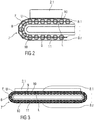
- FIGS. 2 and 3 show a side view of a section of a possible embodiment of a transport unit 7 a transport device 6.1 to 6.x and in a side view of the complete transport unit 7 and arranged on the transport unit 7 storage platform 2.1.
- the transport unit 7 comprises a conveyor belt 8, which is formed from a plurality of band members 8.1 to 8.z connected to one another as a chain.
- a conveying surface F of the conveyor belt 8 runs parallel to an underside U of the storage platform 2.1.
- the rolling elements 10 are formed as a hollow cylinder and disposed in a WälzMechkafig 11, wherein the WälzMechkafig 11 is formed band-shaped and flat sides of the belt parallel to the bearing surface L of the conveyor belt 8.
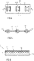
- FIGS. 4 and 5 is shown in various sectional views formed from the rolling elements 10 and the WälzMechharifig 11 rolling bearing.
- the band-shaped rolling body cage 11 has recesses 11.1, which on two opposite edge regions fastening structures 11.2, 11.3, which engage in the cavity of the rolling element 10. In this case, vertical axes of the rolling bodies 10 extend in a plane with the band-shaped rolling element cage 11.
- FIG. 6 shows a side view of a section of another embodiment of the transport unit 7 of the transport device 6.1 to 6.x.
- the bearing surface L facing a plurality of circular cylindrical rolling elements 10 is arranged.
- the rolling elements 10 are arranged in a plane and mounted on a support frame 14 axially and radially.
- the rolling elements 10 include in a manner not shown on their end faces in particular pins, which are arranged and stored in corresponding recesses within the support frame 14.
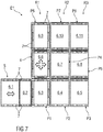
- FIG. 7 shows a plan view of a section of a first embodiment of a parking level E1 of a parking garage 1.1, wherein the Abstellten 2.1 to 2.m are not shown.
- the transfer station 5 comprises two transport devices 6.1, 6.2, each with two transport units 7, by means of which a respective parking platform 2.1 to 2.m transverse to the rows R1 to R3 of Parking spaces P1 to P8 is transportable.
- Each transport unit 7 corresponds in its construction to the FIGS. 2 to 5 ,
- the transport devices 6.3, 6.9, 6.6 of the parking spaces P1, P6 and the conveyor device 4 each comprise four transport units 7, the structure of the representations of FIGS. 2 to 5 equivalent.
- transport devices 6.3, 6.9 is a transport of Abstelldeen 2.1 to 2.m within the row R1 and between the rows R1 and R2 possible.
- Abstelldeen 2.1 to 2.m within the row R1 and between the rows R1 and R2 possible.
- not all transport units 7 are provided with a reference numeral.
- transport devices 6.3, 6.9, 6.6 are designed as a transport frame, wherein in each case two transport units 7 and the associated conveyor belts 8 are arranged on opposite edge sides of the transport frame.
- a transport direction of a pair of opposing conveyor belts 8 runs in the direction of the row-shaped consecutively arranged parking spaces P1 to Pn and a transport direction of the other pair of opposed conveyor belts 8 perpendicular to the direction of the rows of successively arranged parking spaces P1 to Pn.
- a transport device 6.1 to 6.x comprises a plurality of conveyor belts 8 with different transport directions, such as the transport frame described, the conveyor belts 8 of a pair are so variable in their height for a transport direction, i. H. can be raised or lowered, that when transporting a storage platform 2.1 to 2.m in one of the transport directions no contact between the bottom U of the respective storage platform 2.1 to 2.m and the pair of conveyor belts 8 for the other direction of transport consists.
- This raising or lowering takes place in a possible embodiment not shown in detail by means of a motor-driven eccentric and / or pneumatic and / or hydraulic.
- the conveyor belts 8 of a pair which are provided for movement with a transporting direction along a row R1 to R3 are fixed in height, and the conveyor belts 8 of a pair are provided for movement with a transporting direction transverse to a row R1 to R3 are variable in height.
- the conveyor belts 8 of a pair which are provided for movement with the transporting direction along a row R1 to R3 are variable in height and the conveyor belts 8 of a pair which are movable for movement with the transporting direction transverse to a row R1 to R3 are provided, fixed in height.
- the maximum utilization of the illustrated parking level E1 is a provision of at least two free parking spaces P1 to Pn or the possibility of temporary storage of at least two Abstellten 2.1 to 2.m required so that at any time a transport of a parked vehicle 3 from any parking space P1 to Pn to the transfer station 5 or in another parking space P1 to Pn is possible.
- FIG. 8 is a plan view of a section of a second embodiment of a parking level E1 of a parking garage 1.1 shown, with the Abstellten 2.1 to 2.m are not shown.
- the illustrated parking level E1 For maximum utilization of the illustrated parking level E1 is only a provision of at least one free parking space P1 to Pn or the possibility of temporary storage of at least one storage platform 2.1 to 2.m required so that at any time a transport of a parked vehicle 3 from any parking space P1 until Pn to the transfer station 5 or in another parking space P1 to Pn is possible.
- FIG. 9 shows a plan view of a third embodiment of a parking level E1 of the parking garage 1.1, wherein the parking platforms 2.1 to 2.m are not shown.
- All transport devices 6.10 to 6.x of the parking spaces P1 to Pn and the conveyor device 4 each comprise four transport units 7, so that the parking platforms 2.1 to 2.m are transported in an arbitrary manner both within all rows R1 to R6 and between all rows R1 to R6 can be.
- the transport devices 6.1 to 6.9 of the transfer stations 5 each comprise two transport units 7, which in each case have the same transport direction for feeding a parking platform 2.1 to 2.m into the parking garage 1.1. Furthermore, all transfer stations 5 include a rotating device for rotating the respective transport device 6.1 to 6.9 and the respective storage platform 2.1 to 2.m about the vertical axis.
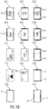
- FIG. 10 are plan views of various embodiments of transport devices 6.1 to 6.9 of the parking garage 1.1 shown. Furthermore, various embodiments of Abstellten 2.1 to 2.5 are shown.
- the transport devices 6.1 to 6.3 are provided for use for the elevator installation 4.1 of the conveyor device 4, wherein the possible transport directions along a row R1 to R6 (transport device 6.1), transverse to a row R1 to R6 (transport device 6.2) or along and across a row R1 to R6 (transport device 6.3) run.
- the transport devices 6.4 to 6.6 are provided for use for a transfer station 5, with their possible transport directions along a row R1 to R6 (transport device 6.4), transverse to a row R1 to R6 (transport device 6.5) or along and across to a row R1 to R6 (Transport device 6.6) run. Furthermore, the transport devices 6.4 to 6.6 are each coupled to a rotating device for rotating the respective transport device 6.4 to 6.6 about the vertical axis or include these.
- the transport devices 6.7 to 6.9 are provided for use in a parking space P1, with their possible transport directions along a row R1 to R6 (transport device 6.7), transverse to a row R1 to R6 (transport device 6.8) or along and across a row R1 to R6 (Transport device 6.9) run.
- the illustrated Abstelloen 2.1 to 2.4 are each designed to accommodate at least one vehicle 3, wherein the Abstello 2.1 is formed such that at least one bike is safely off on this.
- fastening devices for securing the bicycle are provided.
- the parking platform 2.2 is designed to park a vehicle 3, in particular a passenger car, and in one possible embodiment comprises structures which prevent or at least inhibit the vehicle 3 from rolling away.
- the Abstello 2.3 is designed such that at least one motorcycle is safely off on this.
- fastening devices for securing the motorcycle are provided.
- the storage platform 2.4 is designed to park a completely electrically operated vehicle 3 or a hybrid vehicle, and in one possible embodiment comprises structures which prevent or at least inhibit the vehicle 3 from rolling away. Furthermore, the storage platform 2.4 comprises a charging device 12 for charging an electrical storage of the vehicle 3. For coupling this charging device 12, the parking platform comprises, in a manner not shown, an electrical contact device by means of which it can be coupled to an electrical network in the corresponding parking space P1 to Pn. Such an electrical contact device can all Abstellovaen 2.1 to 2.m, regardless of their other training include.
- the storage platform 2.5 is provided and designed to receive a vehicle designed as a storage container 3, so that a use of the automatic parking garage 1.1 as a multifunctional storage building is possible and thus an increase in utilization can be achieved if necessary.
- all storage platforms 2.1 to 2.m are subsequently expandable and / or convertible in such a way that they can be easily adapted for use with other functions.
- all parking platforms 2.1 to 2.m can be adapted or designed in such a way that a vehicle 3 configured as a storage container can be arranged thereon.
- FIG. 11 shows a block diagram of a device 13 for controlling an operation of the parking garage 1.1.
- the device 13 comprises an input and output unit 13.1, by means of which a user receives, for example, a parking ticket, specifies his desired parking duration and can make a payment.
- the input and output unit 13.1 is arranged, for example, stationary on the parking garage 1.1.
- user data processing unit 15 shown in detail provided with a corresponding data processing and / or application program.
- the input and output unit 13.1 is wireless or wired coupled to a computing device 13.2.
- the computing device 13.2 comprises at least one data processing program by means of which at least one order management and positioning of the parked vehicles 3 in the parking garage 1.1 are carried out and optimized.
- a sequence of orders in particular a sequence of inclusions and outsourcing, determined and stored.
- the computing device 13.2 is embodied such that a positioning of a storage platform 2.1 to 2.m within the parking garage 1.1 is performed as a function of a storage time of a vehicle 3 to be stored in the future and / or as a function of a storage time of a stored vehicle 3.
- a position i. H. a parking space P1 to Pn, for positioning the respective storage platform 2.1 to 2.m selected such that a path and time required for transporting the respective storage platform 2.1 to 2.m to the transfer station 5 are minimized.
- the positioning of the Abstelldeen 2.1 to 2.m such that when a choice of parking space P1 to Pn is the same distance is considered for the conveying device 4, wherein a parking space P1 to Pn is selected at a high distance to the conveyor device 4 at a high time to the occurrence of storage or Auslagerungszeitifiess and at a shorter time than the high time to the occurrence of storage or Auslagerungszeitifiess a parking space P1 to Pn at a distance less than the high distance to the conveyor 4 is selected.
- an empty parking platform 2.1 to 2.m will be located near the conveyor device 4, in particular in a parking space P1 to Pn arranged immediately adjacent to the conveyor device 4 arranged.
- the parking platform 2.1 to 2.m occupied by the vehicle 3 is arranged in the vicinity of the conveying device 4, in particular in a directly adjacent to the conveying device 4 Parking space P1 to Pn, arranged.
- the computing device 13.2 is designed in a possible embodiment such that the positioning of a parking platform 2.1 to 2.m occupied by a vehicle 3 is already carried out during its storage. This is done in particular if the time of removal is already known during storage. If, for example, it is already known during storage that a user would like to pick up his vehicle 3 from the parking garage 1.1 at a certain time, the parking platform 2.1 to 2.m occupied by the vehicle 3 will already be in storage near the conveyor device 4, in particular in a parking space P1 to Pn arranged immediately adjacent to the conveying device 4, if it is foreseeable that in the meantime no further storage or paging operation impairing the planned paging takes place.
- the computing device 13.2 is designed such that the positioning of a storage platform 2.1 to 2.m based on at least one repositioning between a storage and a removal of a vehicle 3 on this storage platform 2.1 to 2.m and / or between a removal of a Vehicle 3 and a storage of another vehicle 3 on the same Abstellure 2.1 to 2.m is performed.
- the storage platforms 2.1 to 2.m are positioned at time intervals in which an order density is low, as a function of the respective storage time and / or removal time so that they are quickly available at the time of storage or retrieval.
- the corresponding storage platforms 2.1 to 2.m are positioned in the order of their outsourcing times in the vicinity of the conveyor device 4 such that they successively this can be transported to the transfer station 5.
- the computing device 13.2 is coupled to a control device 13.3, which comprises, for example, a programmable logic controller.
- the control device 13.3 controls the transport devices 6.1 to 6.x and thus the transport of the Abstelldeen 2.1 to 2.m. For detecting a position of a storage platform 2.1 to 2.m sensors are provided in a manner not shown.
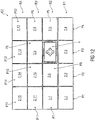
- FIG. 12 is a plan view of a section of a fourth embodiment of a parking level E1 of a parking garage 1.1 shown.
- the Abstellten 2.3, 2.5 are each occupied by vehicles 3, which are to be outsourced next and were therefore positioned immediately adjacent to the conveyor device 4.
- the parking platforms 2.6, 2.9 are each not occupied and next Storage or redistribution of vehicles 3 provided. These storage platforms 2.6, 2.9 were also positioned immediately adjacent to the conveyor 4 for this reason.
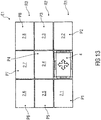
- FIG. 13 shows a plan view of a section of a fifth embodiment of a parking level E1 of a parking garage 1.1.
- all the parking spaces P1 to P8 are occupied by a parking platform 2.1 to 2.8 and each parking platform 2.1 to 2.8 is occupied by a vehicle 3.
- All parking platforms 2.1 to 2.8 are movable both within a row R1 to R3 of parking spaces P1 to P8 and between these rows R1 to R3.
- a vehicle 3 located on the parking platform 2.8 is to be relocated, first the parking platform 2.2 is transported into the transport device 4. Subsequently, a transport of Abstellt 2.3 in the free parking space P2 and a transport of Abstellt 2.8 in the free parking space P3. Subsequently, the storage platform 2.7 is transported into the free parking space P8 and the storage platform 2.4 in the free parking space P7. A transport of the storage platform 2.8 from the parking space P3 now takes place into the free parking space P4 arranged immediately adjacent to the transport device 4, a transport of the storage platform 2.3 from the parking space P2 into the parking space P3 and a transport of the storage platform 2.2 from the transport device 4 into the parking space P2 ,
- deviating repositioning of the parking platforms 2.1 to 2.8 within the parking level E1 is possible in order to position the storage platform 2.8 in a parking space P1, P2, P4 arranged immediately adjacent to the transport device 4.
- a number of the parking platforms 2.1 to 2.m are smaller by at least the value 1 than a number of the parking spaces P1 to Pn.
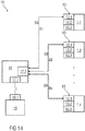
- FIG. 14 1 is a block diagram of one possible embodiment of a control system 16 for a number of automatic parking garages 1.1 to 1.y and the number of automatic parking garages 1.1 to 1.y itself.
- the parking garages 1.1 to 1.y are in particular like a in the FIGS. 1 to 13 described parking garage 1.1 formed.
- the control system 16 comprises at least one user data processing unit 15 which is a mobile terminal, for example a so-called smartphone, a so-called tablet computer or a mobile navigation device, a terminal mounted inside a vehicle 3, for example a navigation device of the vehicle 3.
- a mobile terminal for example a so-called smartphone, a so-called tablet computer or a mobile navigation device, a terminal mounted inside a vehicle 3, for example a navigation device of the vehicle 3.
- the user data processing unit 15 comprises an application program with a user interface for selecting and booking at least one parking space P1 to Pn within an automatic parking garage 1.1 to 1.y.
- the user interface is displayed, for example, on a touch-sensitive screen, which simultaneously forms an input unit of the user data processing unit 15.
- the user data processing unit 15 includes a communication interface 15.1 for communication with a communication interface 17.1 of a central processing unit 17, which is also part of the control system 16.
- the central processing unit 17, which is for example a so-called backend server, comprises, in addition to the communication interface 17.1 for communication with a number of user data processing units 15, at least one further communication interface 17.2 for communication with the number of parking garages 1.1 to 1.y.
- the central arithmetic unit 17 is designed such that it, at least as a function of an arrival time t transmitted from the user data processing unit 15 to the central arithmetic unit 17 during the booking and / or during an approach to the booked parking garage 1.1 and depending on the Occupancy B1 to By of the booked parking garage 1.1 to 1.y storage times and / or removal times of the vehicles to be parked 3 in or out of the respective parking garage 1.1 to 1.y controls.
- the central processing unit 17 sends control commands SB for setting the storage times and / or removal times to the control devices 13.3 of the car parks 1.1 to 1.y.
- the corresponding positioning of the Abstelldeen 2.1 to 2.m takes place according to the description of the FIGS. 11 to 13 by means of the locally provided at the car parks 1.1 to 1.y computing devices 13.2.
- the control system 16 enables a user to search for parking spaces 1.1 to 1.y with free capacities by means of the user data processing unit 15 before a departure to a desired destination and also during a journey there.
- the user specifies, in particular, his estimated time of arrival t and his desired parking duration, so that the central processing unit 17 can determine the occupancy B1 to By of the parking garages 1.1 to 1.y in question.
- the user can select a parking garage 1.1 to 1.y and book a parking space P1 to Pn in it for a specific or indefinite period of time after his arrival time t.
- the time of arrival t in the selected parking garage 1.1 to 1.y while driving a vehicle 3 in response to a residual travel distance and / or depending on traffic data is continuously determined or updated and transmitted to the central processing unit 17.
- this can increase an accuracy of occupancy planning and utilization of the corresponding parking garage 1.1 to 1.y on. Also waiting times for users for storage and retrieval of their vehicles 3 can be minimized.
- the determination and updating of the arrival time t during the journey of the vehicle 3 takes place, for example, by means of the user data processing unit 15.
Applications Claiming Priority (1)
| Application Number | Priority Date | Filing Date | Title |
|---|---|---|---|
| DE102017202880.7A DE102017202880A1 (de) | 2017-02-22 | 2017-02-22 | Steuerungssystem für automatische Parkhäuser |
Publications (1)
| Publication Number | Publication Date |
|---|---|
| EP3366869A1 true EP3366869A1 (fr) | 2018-08-29 |
Family
ID=61256689
Family Applications (1)
| Application Number | Title | Priority Date | Filing Date |
|---|---|---|---|
| EP18157874.1A Pending EP3366869A1 (fr) | 2017-02-22 | 2018-02-21 | Système de commande pour parcs à voitures automatiques |
Country Status (2)
| Country | Link |
|---|---|
| EP (1) | EP3366869A1 (fr) |
| DE (1) | DE102017202880A1 (fr) |
Cited By (2)
| Publication number | Priority date | Publication date | Assignee | Title |
|---|---|---|---|---|
| CN113882290A (zh) * | 2021-08-19 | 2022-01-04 | 宁波工程学院 | 一种新型坡面安全减速带 |
| CN114120697A (zh) * | 2021-10-20 | 2022-03-01 | 深圳市捷顺科技实业股份有限公司 | 一种应用于停车场的三方通话方法以及装置 |
Families Citing this family (3)
| Publication number | Priority date | Publication date | Assignee | Title |
|---|---|---|---|---|
| CN113119923B (zh) * | 2019-12-31 | 2023-03-28 | 国创移动能源创新中心(江苏)有限公司 | 定位泊车系统和方法 |
| DE102020118417A1 (de) | 2020-07-13 | 2022-01-13 | Wöhr Autoparksysteme GmbH | Parkanlage für Kraftfahrzeuge |
| DE102022113339A1 (de) | 2022-05-25 | 2023-11-30 | Klaus Multiparking Gmbh | Parkanlage und Verfahren zu deren Betrieb |
Citations (6)
| Publication number | Priority date | Publication date | Assignee | Title |
|---|---|---|---|---|
| US4312623A (en) * | 1979-03-15 | 1982-01-26 | Eaton-Kenway, Inc. | High through-put materials handling system and method |
| DE9315932U1 (de) * | 1993-02-04 | 1994-02-03 | Geilersdorfer Josef | Tiefgarage |
| DE10255945A1 (de) * | 2002-11-14 | 2004-06-09 | Shb Saalfelder Hebezeugbau Gmbh | Verfahren und Vorrichtung zum Ein- und Auslagern von Fahrzeugen in automatischen Parkhäusern |
| US20130085596A1 (en) * | 2011-10-03 | 2013-04-04 | Unitronics Parking Solutions Ltd. | Automated parking system |
| WO2015114592A1 (fr) * | 2014-01-30 | 2015-08-06 | Universidade Do Porto | Dispositif et procédé pour parc de stationnement automatisé pour véhicules autonomes reposant sur un réseau véhiculaire |
| DE102014221754A1 (de) * | 2014-10-27 | 2016-04-28 | Robert Bosch Gmbh | Verfahren zum Durchführen eines automatischen Parkvorgangs eines Fahrzeugs |
-
2017
- 2017-02-22 DE DE102017202880.7A patent/DE102017202880A1/de active Pending
-
2018
- 2018-02-21 EP EP18157874.1A patent/EP3366869A1/fr active Pending
Patent Citations (6)
| Publication number | Priority date | Publication date | Assignee | Title |
|---|---|---|---|---|
| US4312623A (en) * | 1979-03-15 | 1982-01-26 | Eaton-Kenway, Inc. | High through-put materials handling system and method |
| DE9315932U1 (de) * | 1993-02-04 | 1994-02-03 | Geilersdorfer Josef | Tiefgarage |
| DE10255945A1 (de) * | 2002-11-14 | 2004-06-09 | Shb Saalfelder Hebezeugbau Gmbh | Verfahren und Vorrichtung zum Ein- und Auslagern von Fahrzeugen in automatischen Parkhäusern |
| US20130085596A1 (en) * | 2011-10-03 | 2013-04-04 | Unitronics Parking Solutions Ltd. | Automated parking system |
| WO2015114592A1 (fr) * | 2014-01-30 | 2015-08-06 | Universidade Do Porto | Dispositif et procédé pour parc de stationnement automatisé pour véhicules autonomes reposant sur un réseau véhiculaire |
| DE102014221754A1 (de) * | 2014-10-27 | 2016-04-28 | Robert Bosch Gmbh | Verfahren zum Durchführen eines automatischen Parkvorgangs eines Fahrzeugs |
Cited By (2)
| Publication number | Priority date | Publication date | Assignee | Title |
|---|---|---|---|---|
| CN113882290A (zh) * | 2021-08-19 | 2022-01-04 | 宁波工程学院 | 一种新型坡面安全减速带 |
| CN114120697A (zh) * | 2021-10-20 | 2022-03-01 | 深圳市捷顺科技实业股份有限公司 | 一种应用于停车场的三方通话方法以及装置 |
Also Published As
| Publication number | Publication date |
|---|---|
| DE102017202880A1 (de) | 2018-08-23 |
Similar Documents
| Publication | Publication Date | Title |
|---|---|---|
| EP3366869A1 (fr) | Système de commande pour parcs à voitures automatiques | |
| EP3703902B1 (fr) | Système de transport et procédé de transport simultané de pièces et de monteurs | |
| DE3930425C2 (de) | Verfahren zum Steuern der Bewegung von Transportfahrzeugen | |
| EP3350389B1 (fr) | Parking automatique ä plusieurs étages | |
| EP2607292B1 (fr) | Système de transport des marchandises disposées sur les aides auxiliaires | |
| WO2016030034A1 (fr) | Système automatique de stationnement pour véhicules | |
| DE102015203506A1 (de) | Automobile Transporteinheit zum Positionieren von Fahrzeugen, Verfahren dafür sowie Parksystem | |
| CH714742A1 (de) | Fördermodul zum waagrechten Fördern von Gütereinheiten in zwei zueinander senkrecht stehenden Richtungen, sowie Anlage. | |
| WO2011128384A1 (fr) | Système de stockage et de transport pour récipients de transport | |
| DE102016108992A1 (de) | Verfahren und Vorrichtung zum Lagern von Stückgut mit überbrückbaren Regalreihen | |
| EP3154877B1 (fr) | Système de stockage | |
| EP3782939B1 (fr) | Système de transport autonome | |
| EP2766284A1 (fr) | Dispositif de déplacement d'unités de transport | |
| DE102016217632A1 (de) | Automatisches Parkhaus | |
| DE4243377A1 (de) | Automatisches Parkiersystem | |
| EP2041005B1 (fr) | Dispositif et procédé d'entreposage d'unités de stockage | |
| EP0505808A2 (fr) | Garage pour véhicules automobiles | |
| EP3704002B1 (fr) | Dispositif de stockage plan ainsi que procédé de transport de carrosseries de véhicule ou de logements de carrosserie de véhicule | |
| DE102015217960A1 (de) | Automatisches Parkhaus | |
| DE102015217959B4 (de) | Verfahren und Vorrichtung zur Steuerung eines automatischen Parkhauses | |
| EP4085807B1 (fr) | Procédé de chargement et de déchargement de robots de nettoyage dans un chariot et système de nettoyage | |
| DE102015217965B4 (de) | Sensorsystem und automatisches Parkhaus | |
| EP4269321A2 (fr) | Dispositif de transport pour porteurs de charge | |
| DE102021122379B3 (de) | Transportsystem für ein modulares Montagesystem und Verfahren zum Betreiben des Transportsystems | |
| DE102017004878A1 (de) | Ein Verfahren zur Ablaufsteuerung von Umschlagterminals nach vorrangig auszuführenden Schleifenprozesse der eingesetzten Anlagen zur Erzielung kürzest möglicher Verfahrwege und durch Zuordnung von weiteren Aufträgen in unmittelbarer Nähe zum zuletzt abgeschlossenen Auftrag. Daran angepasst sind technische Fahrzeuge, Anlagen, Steuerungen, Programme und Vorrichtungen, sowie bauliche Optimierungen in Umschlagterminals. |
Legal Events
| Date | Code | Title | Description |
|---|---|---|---|
| PUAI | Public reference made under article 153(3) epc to a published international application that has entered the european phase |
Free format text: ORIGINAL CODE: 0009012 |
|
| STAA | Information on the status of an ep patent application or granted ep patent |
Free format text: STATUS: THE APPLICATION HAS BEEN PUBLISHED |
|
| AK | Designated contracting states |
Kind code of ref document: A1 Designated state(s): AL AT BE BG CH CY CZ DE DK EE ES FI FR GB GR HR HU IE IS IT LI LT LU LV MC MK MT NL NO PL PT RO RS SE SI SK SM TR |
|
| AX | Request for extension of the european patent |
Extension state: BA ME |
|
| STAA | Information on the status of an ep patent application or granted ep patent |
Free format text: STATUS: REQUEST FOR EXAMINATION WAS MADE |
|
| 17P | Request for examination filed |
Effective date: 20190227 |
|
| RBV | Designated contracting states (corrected) |
Designated state(s): AL AT BE BG CH CY CZ DE DK EE ES FI FR GB GR HR HU IE IS IT LI LT LU LV MC MK MT NL NO PL PT RO RS SE SI SK SM TR |
|
| STAA | Information on the status of an ep patent application or granted ep patent |
Free format text: STATUS: REQUEST FOR EXAMINATION WAS MADE |
|
| RAP1 | Party data changed (applicant data changed or rights of an application transferred) |
Owner name: FIRST MOVE! AG |
|
| STAA | Information on the status of an ep patent application or granted ep patent |
Free format text: STATUS: EXAMINATION IS IN PROGRESS |
|
| 17Q | First examination report despatched |
Effective date: 20221021 |