EP3366626B1 - Elevator safety system and method of monitoring an elevator system - Google Patents
Elevator safety system and method of monitoring an elevator system Download PDFInfo
- Publication number
- EP3366626B1 EP3366626B1 EP17157411.4A EP17157411A EP3366626B1 EP 3366626 B1 EP3366626 B1 EP 3366626B1 EP 17157411 A EP17157411 A EP 17157411A EP 3366626 B1 EP3366626 B1 EP 3366626B1
- Authority
- EP
- European Patent Office
- Prior art keywords
- elevator
- elevator car
- limit
- landing
- determining
- Prior art date
- Legal status (The legal status is an assumption and is not a legal conclusion. Google has not performed a legal analysis and makes no representation as to the accuracy of the status listed.)
- Revoked
Links
Images
Classifications
-
- B—PERFORMING OPERATIONS; TRANSPORTING
- B66—HOISTING; LIFTING; HAULING
- B66B—ELEVATORS; ESCALATORS OR MOVING WALKWAYS
- B66B5/00—Applications of checking, fault-correcting, or safety devices in elevators
- B66B5/0006—Monitoring devices or performance analysers
- B66B5/0018—Devices monitoring the operating condition of the elevator system
- B66B5/0031—Devices monitoring the operating condition of the elevator system for safety reasons
-
- B—PERFORMING OPERATIONS; TRANSPORTING
- B66—HOISTING; LIFTING; HAULING
- B66B—ELEVATORS; ESCALATORS OR MOVING WALKWAYS
- B66B5/00—Applications of checking, fault-correcting, or safety devices in elevators
- B66B5/02—Applications of checking, fault-correcting, or safety devices in elevators responsive to abnormal operating conditions
- B66B5/021—Applications of checking, fault-correcting, or safety devices in elevators responsive to abnormal operating conditions the abnormal operating conditions being independent of the system
-
- B—PERFORMING OPERATIONS; TRANSPORTING
- B66—HOISTING; LIFTING; HAULING
- B66B—ELEVATORS; ESCALATORS OR MOVING WALKWAYS
- B66B1/00—Control systems of elevators in general
- B66B1/24—Control systems with regulation, i.e. with retroactive action, for influencing travelling speed, acceleration, or deceleration
- B66B1/28—Control systems with regulation, i.e. with retroactive action, for influencing travelling speed, acceleration, or deceleration electrical
-
- B—PERFORMING OPERATIONS; TRANSPORTING
- B66—HOISTING; LIFTING; HAULING
- B66B—ELEVATORS; ESCALATORS OR MOVING WALKWAYS
- B66B1/00—Control systems of elevators in general
- B66B1/34—Details, e.g. call counting devices, data transmission from car to control system, devices giving information to the control system
- B66B1/3407—Setting or modification of parameters of the control system
-
- B—PERFORMING OPERATIONS; TRANSPORTING
- B66—HOISTING; LIFTING; HAULING
- B66B—ELEVATORS; ESCALATORS OR MOVING WALKWAYS
- B66B1/00—Control systems of elevators in general
- B66B1/34—Details, e.g. call counting devices, data transmission from car to control system, devices giving information to the control system
- B66B1/3492—Position or motion detectors or driving means for the detector
-
- B—PERFORMING OPERATIONS; TRANSPORTING
- B66—HOISTING; LIFTING; HAULING
- B66B—ELEVATORS; ESCALATORS OR MOVING WALKWAYS
- B66B1/00—Control systems of elevators in general
- B66B1/34—Details, e.g. call counting devices, data transmission from car to control system, devices giving information to the control system
- B66B1/36—Means for stopping the cars, cages, or skips at predetermined levels
- B66B1/40—Means for stopping the cars, cages, or skips at predetermined levels and for correct levelling at landings
-
- B—PERFORMING OPERATIONS; TRANSPORTING
- B66—HOISTING; LIFTING; HAULING
- B66B—ELEVATORS; ESCALATORS OR MOVING WALKWAYS
- B66B13/00—Doors, gates, or other apparatus controlling access to, or exit from, cages or lift well landings
- B66B13/24—Safety devices in passenger lifts, not otherwise provided for, for preventing trapping of passengers
-
- B—PERFORMING OPERATIONS; TRANSPORTING
- B66—HOISTING; LIFTING; HAULING
- B66B—ELEVATORS; ESCALATORS OR MOVING WALKWAYS
- B66B3/00—Applications of devices for indicating or signalling operating conditions of elevators
- B66B3/002—Indicators
-
- B—PERFORMING OPERATIONS; TRANSPORTING
- B66—HOISTING; LIFTING; HAULING
- B66B—ELEVATORS; ESCALATORS OR MOVING WALKWAYS
- B66B5/00—Applications of checking, fault-correcting, or safety devices in elevators
- B66B5/02—Applications of checking, fault-correcting, or safety devices in elevators responsive to abnormal operating conditions
- B66B5/027—Applications of checking, fault-correcting, or safety devices in elevators responsive to abnormal operating conditions to permit passengers to leave an elevator car in case of failure, e.g. moving the car to a reference floor or unlocking the door
-
- B—PERFORMING OPERATIONS; TRANSPORTING
- B66—HOISTING; LIFTING; HAULING
- B66B—ELEVATORS; ESCALATORS OR MOVING WALKWAYS
- B66B5/00—Applications of checking, fault-correcting, or safety devices in elevators
- B66B5/02—Applications of checking, fault-correcting, or safety devices in elevators responsive to abnormal operating conditions
- B66B5/04—Applications of checking, fault-correcting, or safety devices in elevators responsive to abnormal operating conditions for detecting excessive speed
-
- B—PERFORMING OPERATIONS; TRANSPORTING
- B66—HOISTING; LIFTING; HAULING
- B66B—ELEVATORS; ESCALATORS OR MOVING WALKWAYS
- B66B9/00—Kinds or types of lifts in, or associated with, buildings or other structures
-
- B—PERFORMING OPERATIONS; TRANSPORTING
- B66—HOISTING; LIFTING; HAULING
- B66B—ELEVATORS; ESCALATORS OR MOVING WALKWAYS
- B66B1/00—Control systems of elevators in general
- B66B1/24—Control systems with regulation, i.e. with retroactive action, for influencing travelling speed, acceleration, or deceleration
- B66B1/28—Control systems with regulation, i.e. with retroactive action, for influencing travelling speed, acceleration, or deceleration electrical
- B66B1/285—Control systems with regulation, i.e. with retroactive action, for influencing travelling speed, acceleration, or deceleration electrical with the use of a speed pattern generator
Definitions
- the present invention relates to an elevator safety system and to a method of monitoring an elevator system.
- Elevator systems usually comprise an elevator safety system which is configured for monitoring and checking the operation of the elevator system in order to stop any further operation of the elevator system, in particular any movement of the elevator car, in case an unsafe condition of the elevator system occurs.
- an elevator safety system which is configured for monitoring and checking the operation of the elevator system in order to stop any further operation of the elevator system, in particular any movement of the elevator car, in case an unsafe condition of the elevator system occurs.
- Elevator safety systems in particular are configured to ensure that all doors, in particular landing doors and door(s) of the elevator car, are closed unless the elevator car is stopped at a landing.
- US 2009/277724 A1 discloses an elevator system having an elevator shaft and at least one elevator cabin movable inside the elevator shaft.
- the elevator system further comprises a decentralized control system having a first analysis unit associated with one of the at least one elevator cabin, a second analysis unit associated with the elevator shaft, and a number of third analysis units.
- the first, second, and third analysis units are connected to one another via a bus connection, wherein signal transmission occurs via the bus connection using a safety protocol such that the transmission of safety-relevant data is allowed between the analysis units.
- the safety protocol is structured such that transmission errors are detected and data corruption is indicated.
- the first analysis unit associated with the elevator cabin is connected to sensors for securely detecting the position of the elevator cabin, allowing control of safety devices of the elevator system.
- the second analysis unit is connected to a drive of the elevator system.
- US 2004/173413 A1 relates to a method for preventing an inadmissibly high speed of an elevator car of an elevator by continuously monitoring the actual speed of the elevator car by means of a speed monitoring device. If an excess speed is detected, the speed monitoring device, depending on the excess speed situation, is adapted to activate at least three different breaking measures successively.
- EP 2 583 928 A1 proposes an elevator system equipped with an unintended car movement protection, which assesses open-door movement and stops the car if the car moves up or down relative to the landing floor with the car doors and/or landing doors being opened, and is further provided with: a car door switch that detects when car doors are opened and a landing door switch that detects when landing doors are opened, a detection device that detects the velocity and movement distance of the car, a position sensor that detects the reference floor position at each storey, and a safety controller that determines an open-door movement abnormality on the basis of the results detected by the detection device and the position sensor, using a car-speed abnormality determination threshold value that is defined to the car position.
- an elevator safety system for an elevator system with at least one door and with an elevator car, which is movable along a hoistway between a plurality of landings, comprises: at least one position sensor, which is configured for determining a position value representing the position of the elevator car within the hoistway; at least one door sensor, which is configured for detecting whether the at least one door is closed; a limit setting unit, which is configured for determining an operation status from a plurality of operation statuses of the elevator car and for setting an upper position limit and a lower position limit according to the determined operation status; and a comparison unit, which is configured for comparing the determined position value with the set position limit and for determining an error condition, if the position value is not in compliance with the at least one position limit and the at least one door sensor indicates that at least one door is not closed.
- the operation statuses of the elevator car comprise a first operation status corresponding to a destination landing approaching operation in which the elevator car approaches a destination landing and selected doors of the elevator system are allowed to start opening before the elevator car as reached its final position at the destination landing, and a second operation status corresponding to re-leveling operation in which the elevator car has reached the destination landing and is stopping at the destination landing.
- the difference between the upper and lower position limits is bigger than the difference between the upper and lower position limits in the re-leveling operation.
- a method of monitoring an elevator system with at least one door and with an elevator car, which is movable along a hoistway between a plurality of landings comprises: determining the operation status of the elevator car and setting at least one position limit according to the operation status of the elevator car; determining whether all doors are closed; determining a position value representing the position of the elevator car within the hoistway; and comparing the determined position value with the position limit and determining an error condition of the elevator system if it is determined that the position value is not in compliance with the at least one position limit and that at least one door is not closed.
- the operation statuses of the elevator car comprise a first operation status corresponding to a destination landing approaching operation in which the elevator car approaches a destination landing and selected doors of the elevator system are allowed to start opening before the elevator car as reached its final position at the destination landing, and a second operation status corresponding to re-leveling operation in which the elevator car has reached the destination landing and is stopping at the destination landing.
- the difference between the upper and lower position limits is bigger than the difference between the upper and lower position limits in the re-leveling operation.
- Exemplary embodiments of the invention further include an elevator system comprising at least one door, an elevator car, which is movable along a hoistway, and an elevator safety system according to an exemplary embodiment of the invention.
- Exemplary embodiments of the invention allow to adjust the setting of the at least one position limit according to the current operation status of the elevator car. They in particular allow to optimize the regions (door zones) in which the doors of the elevator system may be opened for each operation status of the elevator system. As a result, the elevator system may be operated more efficiently without deteriorating the operational safety of the elevator system.
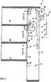
- the elevator system 2 comprises a hoistway 4 vertically extending between a plurality of floors/landings 6, 8, 9.
- a landing door 61, 81, 91 providing access to the hoistway 4 and a control panel 62, 82, 92 are arranged at each of the landings 6, 8, 9, respectively.
- An elevator car 12 and a corresponding counterweight 14 are movably suspended within the hoistway 4 by means of a tension member 16 allowing the elevator car 12 and the counterweight 14 to move vertically along the hoistway 4 in opposite directions.
- the elevator car 12 is provided with at least one elevator car door 20 and an elevator car control panel 22.
- the tension member 16 may be a rope, a belt or a combination of ropes/belts.
- the tension member 16 extends over a drive sheave 18, which is provided in an upper area of the hoistway 4.
- Figure 1 depicts a simple 1:1 suspension of the elevator car 12.
- suspensions such as 2:1, 4:1, 8:1 etc. and similar suspensions, which may include, or may not include, a counterweight 14, may be used in elevator systems 2 according to exemplary embodiments of the invention, as well.
- the drive sheave 18 is driven by a drive machine (not shown) comprising a motor, thus forming a traction drive.
- the motor driving the drive sheave 18 is controlled by an elevator control 28 based on input provided via the control panels 62, 82, 92, 22 according to the passengers' requests.
- Other drive machines than a traction drive are conceivable as well, e.g. linear drives or hydraulic drives.
- the elevator car 12 is provided with a position sensor 25, which is configured for providing a position value indicating the current position of the elevator car 12 while moving along the hoistway 4.
- the position sensor 25 may include a speed sensor 27 and/or an acceleration sensor (not shown) in order to determine the current position of the elevator car 12 within the hoistway 4 by measuring the current speed and/or acceleration of the elevator car 12 and integrating the measured speed and/or acceleration over time.
- the position sensor 25 may interact with a wall 5 of the hoistway 4 and/or markers 24, 26, 64, 84, 94, which are provided at the wall 5 of the hoistway 4, in order to determine the current position of the elevator car 12 within the hoistway 4.
- the position sensor 25 in particular may (re-)calibrate the position value, which has been determined by integrating the speed and/or the acceleration of the elevator car 12 over time, every time the position sensor 25 passes one of the markers 24, 26, 64, 84, 94.
- a marker 64, 84, 94 is positioned at each landing 6, 8, 9, in particular at the top of the respective landing door 61, 81, 91, respectively.
- Additional markers 24, 26 are arranged at the top of the hoistway 4 and within a pit 10, which is formed at the bottom of the hoistway 4, respectively.
- FIG. 1 The configuration illustrated in Figure 1 , however, is only exemplary. It in particular is not necessary to provide a marker 64, 84, 94 at every landing 6, 8, 9. Further, the markers 64, 84, 94 assigned to the landings 6, 8, 9 may be provided at a different position than the top of the respective landing door 61, 81, 91. In principle, it might be sufficient to provide a single marker 24, 26, 64, 84, 94 at a predefined position within the hoistway 4 in order to (re)calibrate the position information whenever the elevator car 12 passes said marker 24, 26, 64, 84, 94.
- the position information provided by the position sensor 25 may be transmitted to the elevator control 28 by means of a cable (not shown) extending along the hoistway 4, or by means of wireless data transmission.
- the elevator control 28 is configured for controlling the movement of the elevator car 12 along the hoistway 4 by driving the drive sheave 18 based on the position information provided by the position sensor 25.
- the at least one elevator car door 20 and the landing doors 61, 81, 91 are respectively provided with a door sensor 23, 63, 83, 93, which is configured to detect whether the respective door 20, 61, 81, 91 is open or (properly) closed.
- the position sensor 25 and the door sensors 23, 63, 83, 93 are components of an elevator safety system.
- the elevator safety system includes a safety chain 40 comprising a plurality of contactors 42, which are configured for monitoring safety relevant functions of the elevator system 2.
- the elevator safety system in particular is configured to stop any movement of the elevator car 16 if at least one of the contactors 42 of the safety chain 40 is opened.
- the elevator safety system further includes a limit setting unit 32 and a comparison unit 34.
- the limit setting unit 32 and the comparison unit 34 may be integrated with the elevator control 28, as shown in Figure 1 .
- the limit setting unit 32 and the comparison unit 34 may be provided separately from the elevator control 28.
- the limit setting unit 32 is configured for determining a current operation status of the elevator car 12 and for setting at least one position limit according to the determined operation status.
- the limit setting unit 32 may be further configured for setting a speed limit according to the determined operation status.
- the comparison unit 34 is configured for comparing the position value, which has been determined by the position sensor 25, with the position limit set by the limit setting unit 32.
- the comparison unit 34 is configured for determining an error condition, if the determined position value is not in compliance with the at least one position limit and at least one of the door sensors 23, 63, 83, 93 indicates that at least one of the doors 20, 61, 81, 91 is not closed.
- the comparison unit 34 may be further configured for comparing the speed value, which has been determined by the position sensor 25, with the speed limit set by the limit setting unit 32.
- the comparison unit 34 is configured for determining an error condition, if the determined speed value is not in compliance with the speed limit and at least one of the door sensors 23, 63, 83, 93 indicates that at least one of the doors 20, 61, 81, 91 is not closed.
- the elevator safety system may further include a counter 36, which is configured to be incremented every time the comparison unit 34 determines an error condition.
- the counter 36 is configured for counting the events in which an error condition has been determined.
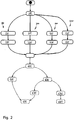
- Figure 2 is a flow chart illustrating the operation of an elevator safety system 2 according to an exemplary embodiment of the invention.
- a first step 100 the current operation status of the elevator car 16 is determined.
- limits for the position and the speed of the elevator car 16 are set according to said determined operation status.
- the operation status of the elevator car 16 in particular may be a destination landing approaching operation 200, in which the elevator car 16 is approaching a destination landing 6, 8, 9 at which it is supposed to be stopped.
- steps 210 and 220 a position limit and a speed limit corresponding to the destination landing approaching operation 200 are set, respectively.
- the operation status of the elevator car 16 may also be a re-leveling operation 300.
- the re-leveling operation 300 is activated after the elevator car 16 has reached its destination landing 6, 8, and has been stopped at said destination landing 6, 8, 9.
- the re-leveling operation is configured to maintain the elevator car 16 at a constant height in level with the floor of the destination landing 6, 8, 9 even if the weight of the elevator car 16 changes due to a changing load, in particular passengers leaving from or entering into the elevator car 16.
- steps 310 and 320 a position limit and a speed limit corresponding to the re-leveling operation 300 are set, respectively.
- the operation status of the elevator car 16 further may be a landing departing operation 400.
- the elevator car 16 is prepared for leaving the current landing 6, 8, 9 in order to allow for a quick start of the elevator 16.
- steps 410 and 420 a position limit and a speed limit corresponding to the landing departing operation 400 are set, respectively.
- the operation status of the elevator car 16 may be an inspection/maintenance operation 500 which is activated during inspection/maintenance of the elevator system 2 in order to allow for a more flexible operation of the elevator system 2.
- steps 510 and 520 a position limit and a speed limit corresponding to the inspection/maintenance operation 500 are set, respectively.
- step 600 the current position and the current speed of the elevator car 16 are checked based on the position and speed values provided by the position sensor 25.
- the comparison unit 34 in particular compares the current position and speed values provided by the position sensor 25 with the respective limits which have been set before in steps 210, 220, 310, 320, 410, 420, or 510, 520 according to the actual status of the elevator car 16.
- step 610 In case the current position and the current speed of the elevator car 16 are in compliance with the respective limits, i.e., in case the current position of the elevator car 16 is within a predetermined range and the current speed of the elevator car 16 is below a predetermined threshold, it is determined that the elevator system 2 is in a safe condition (step 610), the contactors 42 of the safety chain 40 are kept closed and normal operation of the elevator system 2 is continued (step 650).
- step 620 it is checked in step 620 whether the elevator car door 20 and all landing doors 61, 81, 91 are closed.
- At least one contactor 42 of the safety chain 40 is opened (step 660). Interrupting the safety chain 40 stops any further movement of the elevator car 16. Additionally, an alarm message may be sent to a service center requesting a mechanic to visit the elevator system 2 in order to solve the problem and to resume a safe operation of the elevator system 2.
- the counter 36 is incremented.
- the safety chain 40 is interrupted only when the counter 36 exceeds a predetermined threshold.
- a message is sent to the service center requesting a mechanic to visit the elevator system 2 for solving the detected problem if the counter 36 exceeds a first threshold.
- the safety chain 40 is interrupted only when the counter 36 exceeds a second threshold, which is bigger than the first threshold.
- step 650 the elevator safety system starts all over again with step 100 determining the current operation status of the elevator car 16.
- the elevator safety system in particular the comparison unit, may be configured for issuing an alarm signal if an error condition is detected.
- the alarm signal may be transmitted to a service center requesting a mechanic to visit the site in order to check the elevator system and to resume safe operation conditions. Additionally or alternatively, the alarm signal may cause to stop any further movement of the elevator car, e.g. by interrupting the safety chain of the elevator system, in order to prevent an unsafe operation of the elevator system.
- the counter may be incremented every time it is determined that the elevator system is not in a safe condition but in an error condition.
- the safety chain is interrupted only when the counter exceeds a predetermined threshold. In consequence, operation of the elevator system is not unnecessarily stopped if the position and/or time limits are exceeded accidentally only once.
- a message may be sent to the service center in order to request a mechanic to visit the elevator system for solving the detected problem if the counter exceeds a first threshold, but the safety chain is interrupted only when the counter exceeds a second threshold, which is bigger than the first threshold. This allows the operation of the elevator system to be continued if the limits are exceeded only occasionally.
- the elevator safety system causes a mechanic to visit the elevator system in order to check the elevator system and resume a safe operation of the elevator system.
- the elevator safety system may further comprise at least one speed sensor, which is configured for determining a speed value representing the speed of the elevator car when moving within the hoistway.
- at least one speed sensor configured for determining a speed value representing the speed of the elevator car when moving within the hoistway. This allows the elevator system to monitor the operation of the elevator system not only based on the current position of the elevator car, but also based on the current speed of the elevator car. As a result, the safety of the elevator system is further enhanced, since the doors are not allowed to open if the elevator car moves at a speed, which is larger than a predetermined speed limit, even if the elevator car is located within a door zone.
- the limit setting unit in particular may be configured for setting at least one speed limit for the speed of the elevator car within the hoistway according to the determined operation status of the elevator car, and the comparison unit may be configured for determining an error condition if the determined speed value exceeds the at least one set speed limit.
- the limit setting unit is configured for setting an upper position limit and a lower position limit in order to define a door zone or range in which the door(s) are allowed to open if the elevator car is arranged in said door zone or range.
- the door zones or ranges in particular may be centered around the landings and/or around the landing doors in order to allow the door(s) to open as soon as the elevator car enters the respective door zone or range.
- the operation status of the elevator car in particular may be a destination landing approaching operation, in which the elevator car is approaching a destination landing at which it is supposed to be stopped.
- a position limit and a speed limit corresponding to the destination landing approaching operation may be set, respectively.
- the position limit and a speed limit set in the destination landing approaching operation in particular may allow to start opening selected doors of the elevator system, in particular the door(s) of the elevator car and/or the door(s) of the destination landing before the elevator car has reached its final position at the destination landing. This allows passengers to leave from and enter into the elevator car immediately as soon as the elevator car has reached its final position at the destination landing.
- the operation status of the elevator car may be a re-leveling operation, which is activated after the elevator car has reached and has been stopped at a destination landing.
- the re-leveling operation may be configured to maintain the elevator car at a constant height next to the destination landing even if its weight changes due to passengers leaving from or entering into the elevator car.
- the range of allowable positions, the difference between an upper and a lower position limit, and the speed limit corresponding to the re-leveling operation may be smaller than the range of allowable positions and the speed limit corresponding to the destination landing approaching operation, as the elevator car is not supposed to move at all during the re-leveling operation.
- the range of allowable positions and the speed limit corresponding to the re-leveling operation may be smaller than in the destination landing approaching operation without deteriorating the efficiency of the elevator system.
- the operation status of the elevator car may be a landing departing operation in which the elevator car is prepared for leaving the current landing in order to allow for a quick start of the elevator.
- the range of allowable positions and the speed limit corresponding to the re-leveling operation may be larger than the range of allowable positions and the speed limit corresponding to the re-leveling operation.
- the at least one position sensor may be configured for continuously determining the position value and/or the at least one speed sensor may be configured for continuously determining the speed value. Continuously monitoring the position value and/or the speed value of the elevator car enhances the safety of the elevator system even further.
- the elevator safety system is configured to allow operating the elevator system in a rescue mode if an error condition is determined and/or after the safety chain has been interrupted.
- the rescue mode in particular may include moving the elevator car to the next or to a predetermined floor and to allow passengers to leave the elevator car. This prevents passengers from being trapped within the elevator car after an error condition has been detected and/or after the safety chain has been interrupted.
Landscapes
- Engineering & Computer Science (AREA)
- Automation & Control Theory (AREA)
- Computer Networks & Wireless Communication (AREA)
- Structural Engineering (AREA)
- Maintenance And Inspection Apparatuses For Elevators (AREA)
- Elevator Control (AREA)
Description
- The present invention relates to an elevator safety system and to a method of monitoring an elevator system.
- Elevator systems usually comprise an elevator safety system which is configured for monitoring and checking the operation of the elevator system in order to stop any further operation of the elevator system, in particular any movement of the elevator car, in case an unsafe condition of the elevator system occurs.
- Elevator safety systems in particular are configured to ensure that all doors, in particular landing doors and door(s) of the elevator car, are closed unless the elevator car is stopped at a landing.
- Such strict safety requirements, however, restrict the options of operation of the elevator system. This might result in a less efficient operation of the elevator system.
- It therefore would be beneficial to provide an improved elevator safety system, in particular an elevator safety system which allows for a more flexible operation of the elevator system.
-
US 2009/277724 A1 discloses an elevator system having an elevator shaft and at least one elevator cabin movable inside the elevator shaft. The elevator system further comprises a decentralized control system having a first analysis unit associated with one of the at least one elevator cabin, a second analysis unit associated with the elevator shaft, and a number of third analysis units. The first, second, and third analysis units are connected to one another via a bus connection, wherein signal transmission occurs via the bus connection using a safety protocol such that the transmission of safety-relevant data is allowed between the analysis units. The safety protocol is structured such that transmission errors are detected and data corruption is indicated. The first analysis unit associated with the elevator cabin is connected to sensors for securely detecting the position of the elevator cabin, allowing control of safety devices of the elevator system. The second analysis unit is connected to a drive of the elevator system. -
US 2004/173413 A1 relates to a method for preventing an inadmissibly high speed of an elevator car of an elevator by continuously monitoring the actual speed of the elevator car by means of a speed monitoring device. If an excess speed is detected, the speed monitoring device, depending on the excess speed situation, is adapted to activate at least three different breaking measures successively. - In order to reliably detect open-door movement at a shorter movement distance and/or at an earlier point in time, thereby enhancing safety, and maintaining operational efficiency,
EP 2 583 928 A1 proposes an elevator system equipped with an unintended car movement protection, which assesses open-door movement and stops the car if the car moves up or down relative to the landing floor with the car doors and/or landing doors being opened, and is further provided with: a car door switch that detects when car doors are opened and a landing door switch that detects when landing doors are opened, a detection device that detects the velocity and movement distance of the car, a position sensor that detects the reference floor position at each storey, and a safety controller that determines an open-door movement abnormality on the basis of the results detected by the detection device and the position sensor, using a car-speed abnormality determination threshold value that is defined to the car position. - According to an embodiment of the invention an elevator safety system for an elevator system with at least one door and with an elevator car, which is movable along a hoistway between a plurality of landings, comprises: at least one position sensor, which is configured for determining a position value representing the position of the elevator car within the hoistway; at least one door sensor, which is configured for detecting whether the at least one door is closed; a limit setting unit, which is configured for determining an operation status from a plurality of operation statuses of the elevator car and for setting an upper position limit and a lower position limit according to the determined operation status; and a comparison unit, which is configured for comparing the determined position value with the set position limit and for determining an error condition, if the position value is not in compliance with the at least one position limit and the at least one door sensor indicates that at least one door is not closed.
- The operation statuses of the elevator car comprise a first operation status corresponding to a destination landing approaching operation in which the elevator car approaches a destination landing and selected doors of the elevator system are allowed to start opening before the elevator car as reached its final position at the destination landing, and a second operation status corresponding to re-leveling operation in which the elevator car has reached the destination landing and is stopping at the destination landing.
- In the destination landing approaching operation, the difference between the upper and lower position limits is bigger than the difference between the upper and lower position limits in the re-leveling operation.
- According to an embodiment of the invention, a method of monitoring an elevator system with at least one door and with an elevator car, which is movable along a hoistway between a plurality of landings, comprises: determining the operation status of the elevator car and setting at least one position limit according to the operation status of the elevator car; determining whether all doors are closed; determining a position value representing the position of the elevator car within the hoistway; and comparing the determined position value with the position limit and determining an error condition of the elevator system if it is determined that the position value is not in compliance with the at least one position limit and that at least one door is not closed.
- The operation statuses of the elevator car comprise a first operation status corresponding to a destination landing approaching operation in which the elevator car approaches a destination landing and selected doors of the elevator system are allowed to start opening before the elevator car as reached its final position at the destination landing, and a second operation status corresponding to re-leveling operation in which the elevator car has reached the destination landing and is stopping at the destination landing.
- In the destination landing approaching operation, the difference between the upper and lower position limits is bigger than the difference between the upper and lower position limits in the re-leveling operation.
- Exemplary embodiments of the invention further include an elevator system comprising at least one door, an elevator car, which is movable along a hoistway, and an elevator safety system according to an exemplary embodiment of the invention.
- Exemplary embodiments of the invention allow to adjust the setting of the at least one position limit according to the current operation status of the elevator car. They in particular allow to optimize the regions (door zones) in which the doors of the elevator system may be opened for each operation status of the elevator system. As a result, the elevator system may be operated more efficiently without deteriorating the operational safety of the elevator system.
- Exemplary embodiments of the invention will be described in the following with respect to the enclosed figures.
-
Figure 1 shows a schematic view of an elevator system according to an exemplary embodiment of the invention. -
Figure 2 is a flow chart illustrating the operation of an elevator safety system according to an exemplary embodiment of the invention. -
Figure 1 illustrates a schematic view of an elevator system 2 with an elevator safety system according to an exemplary embodiment of the invention. - The elevator system 2 comprises a hoistway 4 vertically extending between a plurality of floors/
landings - A
landing door control panel landings - An
elevator car 12 and acorresponding counterweight 14 are movably suspended within the hoistway 4 by means of atension member 16 allowing theelevator car 12 and thecounterweight 14 to move vertically along the hoistway 4 in opposite directions. - The
elevator car 12 is provided with at least one elevator car door 20 and an elevatorcar control panel 22. - The
tension member 16 may be a rope, a belt or a combination of ropes/belts. Thetension member 16 extends over adrive sheave 18, which is provided in an upper area of the hoistway 4. -
Figure 1 depicts a simple 1:1 suspension of theelevator car 12. The skilled person, however, will easily understand that different suspensions, such as 2:1, 4:1, 8:1 etc. and similar suspensions, which may include, or may not include, acounterweight 14, may be used in elevator systems 2 according to exemplary embodiments of the invention, as well. - The
drive sheave 18 is driven by a drive machine (not shown) comprising a motor, thus forming a traction drive. The motor driving thedrive sheave 18 is controlled by an elevator control 28 based on input provided via thecontrol panels - The
elevator car 12 is provided with aposition sensor 25, which is configured for providing a position value indicating the current position of theelevator car 12 while moving along the hoistway 4. Theposition sensor 25 may include aspeed sensor 27 and/or an acceleration sensor (not shown) in order to determine the current position of theelevator car 12 within the hoistway 4 by measuring the current speed and/or acceleration of theelevator car 12 and integrating the measured speed and/or acceleration over time. Alternatively or additionally, theposition sensor 25 may interact with a wall 5 of the hoistway 4 and/ormarkers elevator car 12 within the hoistway 4. Theposition sensor 25 in particular may (re-)calibrate the position value, which has been determined by integrating the speed and/or the acceleration of theelevator car 12 over time, every time theposition sensor 25 passes one of themarkers - In the embodiment shown in
Figure 1 , amarker landing respective landing door pit 10, which is formed at the bottom of the hoistway 4, respectively. - The configuration illustrated in
Figure 1 , however, is only exemplary. It in particular is not necessary to provide amarker landing markers landings respective landing door single marker elevator car 12 passes saidmarker - The position information provided by the
position sensor 25 may be transmitted to the elevator control 28 by means of a cable (not shown) extending along the hoistway 4, or by means of wireless data transmission. - The elevator control 28 is configured for controlling the movement of the
elevator car 12 along the hoistway 4 by driving thedrive sheave 18 based on the position information provided by theposition sensor 25. - The at least one elevator car door 20 and the
landing doors door sensor respective door - The
position sensor 25 and thedoor sensors safety chain 40 comprising a plurality ofcontactors 42, which are configured for monitoring safety relevant functions of the elevator system 2. The elevator safety system in particular is configured to stop any movement of theelevator car 16 if at least one of thecontactors 42 of thesafety chain 40 is opened. - The elevator safety system further includes a
limit setting unit 32 and acomparison unit 34. Thelimit setting unit 32 and thecomparison unit 34 may be integrated with the elevator control 28, as shown inFigure 1 . In an alternative embodiment, which is not shown in the figures, thelimit setting unit 32 and thecomparison unit 34 may be provided separately from the elevator control 28. - The
limit setting unit 32 is configured for determining a current operation status of theelevator car 12 and for setting at least one position limit according to the determined operation status. Thelimit setting unit 32 may be further configured for setting a speed limit according to the determined operation status. - The
comparison unit 34 is configured for comparing the position value, which has been determined by theposition sensor 25, with the position limit set by thelimit setting unit 32. Thecomparison unit 34 is configured for determining an error condition, if the determined position value is not in compliance with the at least one position limit and at least one of thedoor sensors doors - The
comparison unit 34 may be further configured for comparing the speed value, which has been determined by theposition sensor 25, with the speed limit set by thelimit setting unit 32. Thecomparison unit 34 is configured for determining an error condition, if the determined speed value is not in compliance with the speed limit and at least one of thedoor sensors doors - The elevator safety system may further include a
counter 36, which is configured to be incremented every time thecomparison unit 34 determines an error condition. In other words, thecounter 36 is configured for counting the events in which an error condition has been determined. -
Figure 2 is a flow chart illustrating the operation of an elevator safety system 2 according to an exemplary embodiment of the invention. - In a
first step 100, the current operation status of theelevator car 16 is determined. In the following steps limits for the position and the speed of theelevator car 16 are set according to said determined operation status. - The operation status of the
elevator car 16 in particular may be a destinationlanding approaching operation 200, in which theelevator car 16 is approaching adestination landing steps 210 and 220 a position limit and a speed limit corresponding to the destinationlanding approaching operation 200 are set, respectively. - The operation status of the
elevator car 16 may also be are-leveling operation 300. There-leveling operation 300 is activated after theelevator car 16 has reached itsdestination landing elevator car 16 at a constant height in level with the floor of the destination landing 6, 8, 9 even if the weight of theelevator car 16 changes due to a changing load, in particular passengers leaving from or entering into theelevator car 16. Insteps 310 and 320 a position limit and a speed limit corresponding to there-leveling operation 300 are set, respectively. - The operation status of the
elevator car 16 further may be alanding departing operation 400. In thelanding departing operation 400 theelevator car 16 is prepared for leaving thecurrent landing elevator 16. Insteps 410 and 420 a position limit and a speed limit corresponding to thelanding departing operation 400 are set, respectively. - The operation status of the
elevator car 16 may be an inspection/maintenance operation 500 which is activated during inspection/maintenance of the elevator system 2 in order to allow for a more flexible operation of the elevator system 2. Insteps 510 and 520 a position limit and a speed limit corresponding to the inspection/maintenance operation 500 are set, respectively. - In
step 600 the current position and the current speed of theelevator car 16 are checked based on the position and speed values provided by theposition sensor 25. Thecomparison unit 34 in particular compares the current position and speed values provided by theposition sensor 25 with the respective limits which have been set before insteps elevator car 16. - In case the current position and the current speed of the
elevator car 16 are in compliance with the respective limits, i.e., in case the current position of theelevator car 16 is within a predetermined range and the current speed of theelevator car 16 is below a predetermined threshold, it is determined that the elevator system 2 is in a safe condition (step 610), thecontactors 42 of thesafety chain 40 are kept closed and normal operation of the elevator system 2 is continued (step 650). - In case, however, it is determined that at least one of the current position and the current speed of the
elevator car 16 is not in compliance with the respective limits, i.e., the current position of theelevator car 16 is not within a predetermined range and/or the current speed of theelevator car 16 is above the predetermined threshold, it is checked instep 620 whether the elevator car door 20 and all landingdoors - In case all
doors contactors 42 of thesafety chain 40 are kept closed and normal operation of the elevator system 2 is continued (step 650). - However, if it is detected that at least one of the
doors elevator car 16 are not in compliance with the respective limits, it is determined that the elevators system 2 is not in a safe condition but in an error condition (step 640). - In consequence, at least one
contactor 42 of thesafety chain 40 is opened (step 660). Interrupting thesafety chain 40 stops any further movement of theelevator car 16. Additionally, an alarm message may be sent to a service center requesting a mechanic to visit the elevator system 2 in order to solve the problem and to resume a safe operation of the elevator system 2. - In an alternative embodiment, every time when it is determined that the elevator system 2 is not in a safe condition but in an error condition, the
counter 36 is incremented. In such an embodiment, thesafety chain 40 is interrupted only when thecounter 36 exceeds a predetermined threshold. As a result, the operation of the elevator system 2 is not unnecessarily stopped if the position and/or time limits are exceeded accidentally only once. - In yet another embodiment, a message is sent to the service center requesting a mechanic to visit the elevator system 2 for solving the detected problem if the
counter 36 exceeds a first threshold. However, thesafety chain 40 is interrupted only when thecounter 36 exceeds a second threshold, which is bigger than the first threshold. - During normal operation of the elevator system, the steps indicated in
Figure 2 are continuously repeated; i.e. after reachingstep 650 the elevator safety system starts all over again withstep 100 determining the current operation status of theelevator car 16. - A number of optional features are set out in the following. These features may be realized in particular embodiments, alone or in combination with any of the other features.
- According to one embodiment, the elevator safety system, in particular the comparison unit, may be configured for issuing an alarm signal if an error condition is detected.
- The alarm signal may be transmitted to a service center requesting a mechanic to visit the site in order to check the elevator system and to resume safe operation conditions. Additionally or alternatively, the alarm signal may cause to stop any further movement of the elevator car, e.g. by interrupting the safety chain of the elevator system, in order to prevent an unsafe operation of the elevator system.
- According to one embodiment, the counter may be incremented every time it is determined that the elevator system is not in a safe condition but in an error condition. In such an embodiment, the safety chain is interrupted only when the counter exceeds a predetermined threshold. In consequence, operation of the elevator system is not unnecessarily stopped if the position and/or time limits are exceeded accidentally only once.
- According to one embodiment, a message may be sent to the service center in order to request a mechanic to visit the elevator system for solving the detected problem if the counter exceeds a first threshold, but the safety chain is interrupted only when the counter exceeds a second threshold, which is bigger than the first threshold. This allows the operation of the elevator system to be continued if the limits are exceeded only occasionally. However, the elevator safety system causes a mechanic to visit the elevator system in order to check the elevator system and resume a safe operation of the elevator system.
- According to one embodiment, the elevator safety system may further comprise at least one speed sensor, which is configured for determining a speed value representing the speed of the elevator car when moving within the hoistway. This allows the elevator system to monitor the operation of the elevator system not only based on the current position of the elevator car, but also based on the current speed of the elevator car. As a result, the safety of the elevator system is further enhanced, since the doors are not allowed to open if the elevator car moves at a speed, which is larger than a predetermined speed limit, even if the elevator car is located within a door zone.
- The limit setting unit in particular may be configured for setting at least one speed limit for the speed of the elevator car within the hoistway according to the determined operation status of the elevator car, and the comparison unit may be configured for determining an error condition if the determined speed value exceeds the at least one set speed limit. As a result, the efficiency of the elevator system is further enhanced.
- According to one embodiment, the limit setting unit is configured for setting an upper position limit and a lower position limit in order to define a door zone or range in which the door(s) are allowed to open if the elevator car is arranged in said door zone or range. The door zones or ranges in particular may be centered around the landings and/or around the landing doors in order to allow the door(s) to open as soon as the elevator car enters the respective door zone or range.
- According to one embodiment, the operation status of the elevator car in particular may be a destination landing approaching operation, in which the elevator car is approaching a destination landing at which it is supposed to be stopped. A position limit and a speed limit corresponding to the destination landing approaching operation may be set, respectively.
- The position limit and a speed limit set in the destination landing approaching operation in particular may allow to start opening selected doors of the elevator system, in particular the door(s) of the elevator car and/or the door(s) of the destination landing before the elevator car has reached its final position at the destination landing. This allows passengers to leave from and enter into the elevator car immediately as soon as the elevator car has reached its final position at the destination landing.
- According to one embodiment, the operation status of the elevator car may be a re-leveling operation, which is activated after the elevator car has reached and has been stopped at a destination landing. The re-leveling operation may be configured to maintain the elevator car at a constant height next to the destination landing even if its weight changes due to passengers leaving from or entering into the elevator car.
- The range of allowable positions, the difference between an upper and a lower position limit, and the speed limit corresponding to the re-leveling operation may be smaller than the range of allowable positions and the speed limit corresponding to the destination landing approaching operation, as the elevator car is not supposed to move at all during the re-leveling operation. Thus, the range of allowable positions and the speed limit corresponding to the re-leveling operation may be smaller than in the destination landing approaching operation without deteriorating the efficiency of the elevator system.
- According to one embodiment, the operation status of the elevator car may be a landing departing operation in which the elevator car is prepared for leaving the current landing in order to allow for a quick start of the elevator. In order to enhance the efficiency of the elevator system, the range of allowable positions and the speed limit corresponding to the re-leveling operation may be larger than the range of allowable positions and the speed limit corresponding to the re-leveling operation.
- According to one embodiment, the at least one position sensor may be configured for continuously determining the position value and/or the at least one speed sensor may be configured for continuously determining the speed value. Continuously monitoring the position value and/or the speed value of the elevator car enhances the safety of the elevator system even further.
- According to one embodiment, the elevator safety system is configured to allow operating the elevator system in a rescue mode if an error condition is determined and/or after the safety chain has been interrupted. The rescue mode in particular may include moving the elevator car to the next or to a predetermined floor and to allow passengers to leave the elevator car. This prevents passengers from being trapped within the elevator car after an error condition has been detected and/or after the safety chain has been interrupted.
- While the invention has been described with reference to exemplary embodiments, it will be understood by those skilled in the art that various changes may be made and equivalents may be substituted for elements thereof without departing from the scope of the invention. In addition many modifications may be made to adopt a particular situation or material to the teachings of the invention without departing from the essential scope thereof. Therefore, it is intended that the invention not be limited to the particular embodiment disclosed, but that the invention includes all embodiments falling within the scope of the claims.
-
- 2
- elevator system
- 4
- hoistway
- 5
- wall of the hoistway
- 6, 8, 9
- floors/landings
- 10
- pit
- 12
- elevator car
- 14
- counterweight
- 16
- tension member
- 18
- drive sheave
- 20
- elevator car door
- 22
- elevator car control panel
- 23
- door sensor
- 24
- marker
- 25
- speed sensor
- 26
- marker
- 27
- speed sensor
- 28
- elevator control
- 30
- flow chart of a method of controlling the elevator safety system
- 32
- limit setting unit
- 34
- comparison unit
- 36
- counter
- 61, 81, 91
- landing door
- 63, 83, 93
- door sensor
- 64, 84, 94
- marker
- 100
- determining the current operation status of the elevator car
- 200
- landing approaching operation
- 210
- setting a position limit for the landing approaching operation
- 220
- setting a speed limit for the landing approaching operation
- 300
- re-leveling operation
- 310
- setting a position limit for the re-leveling operation
- 320
- setting a speed limit for the re-leveling operation
- 400
- landing departing operation
- 410
- setting a position limit for the landing departing operation
- 420
- setting a speed limit for the landing departing operation
- 500
- inspection/maintenance operation
- 510
- setting a position limit for the inspection/maintenance operation
- 520
- setting a speed limit for the inspection/maintenance operation
- 610
- determining that the elevator system is in a safe condition
- 620
- checking whether all doors are closed
- 630
- determining that the elevator system is in a safe condition
- 640
- determining that the elevator system is in an error condition
- 650
- continuing normal operation of the elevator system
- 660
- opening the safety chain
Claims (12)
- An elevator safety system for an elevator system (2) with at least one door (20, 61, 81, 91) and with an elevator car (12), which is movable along a hoistway (4) between a plurality of landings (6, 8, 9), wherein the elevator safety system comprises:at least one position sensor (25), which is configured for determining a position value representing the position of the elevator car (12) within the hoistway (4);at least one door sensor (23, 63, 83, 93), which is configured for detecting whether the at least one door (20, 61, 81, 91) is closed;a limit setting unit (32), which is configured for determining an operation status from a plurality of operation statuses of the elevator car (12) and for setting an upper position limit and a lower position limit according to the determined operation status; anda comparison unit (34), which is configured for comparing the determined position value with the set position limit and for determining an error condition if the position value is not in compliance with the at least one position limit and the at least one door sensor (23, 63, 83, 93) indicates that at least one door (20, 61, 81, 91) is not closed;wherein the operation statuses of the elevator car (12) comprise:a first operation status corresponding to a destination landing approaching operation in which the elevator car (12) approaches a destination landing (6, 8, 9) and selected doors (20, 61, 81, 91) of the elevator system (2) are allowed to start opening before the elevator car (12) as reached its final position at the destination landing (6, 8, 9);a second operation status corresponding to a re-leveling operation in which the elevator car (12) has reached the destination landing (6, 8, 9) and is stopping at the destination landing (6, 8, 9); andcharacterized in that the difference between the upper and lower position limits in the destination landing approaching operation is bigger than the difference between the upper and lower position limits in the re-leveling operation.
- The elevator safety system according to claim 1, wherein the comparison unit (34) is configured for issuing an alarm signal if an error condition is detected.
- The elevator safety system according to claim 1 or 2, wherein the operation statuses of the elevator car (12) further comprise a landing departing operation in which the elevator car (12) is prepared for leaving one of the landings (6, 8, 9).
- The elevator safety system according to any of the previous claims, further comprising at least one speed sensor (27), which is configured for determining a speed value representing the speed of the elevator car (12) when moving within the hoistway (4).
- The elevator safety system according to claim 4, wherein the limit setting unit (32) is further configured for setting at least one speed limit for the speed of the elevator car (12) within the hoistway (4) according to the determined operation status of the elevator car (12), and wherein the comparison unit (34) is further configured for determining an error condition if the determined speed value exceeds the at least one set speed limit.
- The elevator safety system according to any of the preceding claims, which is configured for interrupting a safety chain (40) of the elevator system (2) if an error condition is determined.
- The elevator safety system according to any of the preceding claims, which is configured for incrementing a counter (36) every time an error condition is determined, and for interrupting the safety chain (40) of the elevator system (2) when the counter (36) exceeds a predetermined threshold.
- The elevator safety system according to any of the preceding claims, wherein the at least one position sensor (25) is configured for continuously determining the position value and/or the at least one speed sensor (27) is configured for continuously determining the speed value.
- The elevator safety system according to any of the preceding claims, which is configured for allowing to operate the elevator system (2) in a rescue mode if an error condition is determined and/or after the safety chain (40) has been interrupted.
- An elevator system (2) comprising an elevator car (12), which is movable along a hoistway (4), and an elevator safety system according to any of the preceding claims.
- A method of monitoring an elevator system (2) with at least one door (20, 61, 81, 91) and with an elevator car (12), which is movable along a hoistway (4) between a plurality of landings (6, 8, 9), wherein the method comprises:determining the operation status from a plurality of operation statuses of the elevator car (12) and setting an upper position limit and a lower position limit according to the determined operation status of the elevator car (12);determining whether all doors (20, 61, 81, 91) are closed;determining a position value representing the position of the elevator car (12) within the hoistway (4); andcomparing the determined position value with the position limit and determining an error condition of the elevator system (2) if it is determined that the position value is not in compliance with the at least one position limit and that at least one door (20, 61, 81, 91) is not closed;
wherein the operation status of the elevator car (12) comprisesa first operation status corresponding to a destination landing approaching operation in which the elevator car (12) approaches a destination landing (6, 8, 9) and selected doors (20, 61, 81, 91) of the elevator system (2) are allowed to start opening before the elevator car (12) as reached its final position at the destination landing (6, 8, 9) anda second operation status corresponding to a re-leveling operation in which the elevator car (12) has reached the destination landing (6, 8, 9) and is stopping at the destination landing (6, 8, 9);characterized in that the difference between the upper and lower position limits in the destination landing approaching operation is bigger than the difference between the upper and lower position limits in the re-leveling operation. - The method according to claim 11, wherein the operation statuses of the elevator car (12) further comprise a landing departing operation in which the elevator car (12) is prepared for leaving one of the landings (6, 8, 9).
Priority Applications (4)
| Application Number | Priority Date | Filing Date | Title |
|---|---|---|---|
| EP17157411.4A EP3366626B1 (en) | 2017-02-22 | 2017-02-22 | Elevator safety system and method of monitoring an elevator system |
| US15/901,028 US11014781B2 (en) | 2017-02-22 | 2018-02-21 | Elevator safety system and method of monitoring an elevator system |
| KR1020180020523A KR102361312B1 (en) | 2017-02-22 | 2018-02-21 | Elevator safety system and method of monitoring an elevator system |
| CN201810153472.9A CN108455396B (en) | 2017-02-22 | 2018-02-22 | Elevator safety system and method for monitoring an elevator system |
Applications Claiming Priority (1)
| Application Number | Priority Date | Filing Date | Title |
|---|---|---|---|
| EP17157411.4A EP3366626B1 (en) | 2017-02-22 | 2017-02-22 | Elevator safety system and method of monitoring an elevator system |
Publications (2)
| Publication Number | Publication Date |
|---|---|
| EP3366626A1 EP3366626A1 (en) | 2018-08-29 |
| EP3366626B1 true EP3366626B1 (en) | 2021-01-06 |
Family
ID=58108532
Family Applications (1)
| Application Number | Title | Priority Date | Filing Date |
|---|---|---|---|
| EP17157411.4A Revoked EP3366626B1 (en) | 2017-02-22 | 2017-02-22 | Elevator safety system and method of monitoring an elevator system |
Country Status (4)
| Country | Link |
|---|---|
| US (1) | US11014781B2 (en) |
| EP (1) | EP3366626B1 (en) |
| KR (1) | KR102361312B1 (en) |
| CN (1) | CN108455396B (en) |
Families Citing this family (13)
| Publication number | Priority date | Publication date | Assignee | Title |
|---|---|---|---|---|
| DE102015202700A1 (en) * | 2015-02-13 | 2016-08-18 | Thyssenkrupp Ag | Method for operating an elevator system |
| EP3279124B1 (en) * | 2016-08-02 | 2019-10-02 | Kone Corporation | Method, elevator control unit, and elevator system for dynamically adjusting a levelling speed limit of an elevator car |
| ES2882042T3 (en) * | 2018-03-16 | 2021-12-01 | Otis Elevator Co | Automatic rescue operation in an elevator system |
| WO2020027201A1 (en) * | 2018-07-31 | 2020-02-06 | ナブテスコ株式会社 | Inquiry processing device and inquiry processing method |
| EP3608274A1 (en) * | 2018-08-10 | 2020-02-12 | Otis Elevator Company | Enhancing the transport capacity of an elevator system |
| US12060247B2 (en) | 2018-10-18 | 2024-08-13 | Otis Elevator Company | Elevator car leveling sensor |
| CN111071883A (en) * | 2018-10-22 | 2020-04-28 | 千寻位置网络有限公司 | Automatic monitoring method and device for elevator safety and monitoring system for elevator safety |
| EP3656718B1 (en) * | 2018-11-23 | 2025-02-26 | Otis Elevator Company | Elevator safety system with self-diagnostic functionality |
| EP3663248B1 (en) * | 2018-12-03 | 2022-05-11 | Otis Elevator Company | Device and method for monitoring an elevator system |
| EP3686146B1 (en) * | 2019-01-25 | 2022-05-11 | Otis Elevator Company | Controlling movement of an elevator car |
| US11993488B2 (en) * | 2019-09-27 | 2024-05-28 | Otis Elevator Company | Processing service requests in a conveyance system |
| JP2021088437A (en) * | 2019-12-03 | 2021-06-10 | 東芝エレベータ株式会社 | Elevator step notification device |
| EP3878788A1 (en) * | 2020-03-09 | 2021-09-15 | Otis Elevator Company | Elevator safety systems |
Citations (10)
| Publication number | Priority date | Publication date | Assignee | Title |
|---|---|---|---|---|
| US4674604A (en) | 1985-10-21 | 1987-06-23 | Otis Elevator Company | Elevator inner and outer door zone sensor arrangement |
| DE4227113A1 (en) | 1992-08-17 | 1994-02-24 | Bosch Gmbh Robert | Method for error detection when evaluating the output signals of a speed sensor |
| US20040173413A1 (en) | 2001-07-04 | 2004-09-09 | Philipp Angst | Method for preventing an inadmissibly high speed of the load receiving means of an elevator |
| EP1479984A1 (en) | 2003-01-30 | 2004-11-24 | Vaillant GmbH | Method and apparatus for preventive failure detection by electronic controlled device |
| WO2005040027A1 (en) | 2003-10-07 | 2005-05-06 | Otis Elevator Company | Electrical elevator rescue system |
| US20090277724A1 (en) | 2007-08-07 | 2009-11-12 | Gerhard Thumm | Elevator system |
| WO2009156512A1 (en) | 2008-06-27 | 2009-12-30 | Airbus Operations Gmbh | Method for detecting a faulty node |
| EP2402498A1 (en) | 2010-07-02 | 2012-01-04 | Miele & Cie. KG | Method for operating a laundry handling machine with steam creation device and laundry handling machine |
| EP2457860A2 (en) | 2010-11-29 | 2012-05-30 | ThyssenKrupp Aufzugswerke GmbH | Safety device for a lift |
| EP2583928A1 (en) | 2010-06-18 | 2013-04-24 | Hitachi, Ltd. | Elevator system |
Family Cites Families (34)
| Publication number | Priority date | Publication date | Assignee | Title |
|---|---|---|---|---|
| SU1240715A1 (en) * | 1984-02-20 | 1986-06-30 | Всесоюзный Научно-Исследовательский Институт Горной Механики Им.М.М.Федорова | Device for shaping protective tachogram of mine hoist speed limiter |
| US4658935A (en) | 1985-08-05 | 1987-04-21 | Dover Corporation | Digital selector system for elevators |
| JPS62244806A (en) * | 1986-04-17 | 1987-10-26 | Daifuku Co Ltd | Stop and control method for introduction and delivery travel crane |
| US4750591A (en) * | 1987-07-10 | 1988-06-14 | Otis Elevator Company | Elevator car door and motion sequence monitoring apparatus and method |
| CA2161291C (en) | 1994-11-18 | 2006-01-10 | Christian Arpagaus | Excess speed detector with multiple light barrier |
| KR0186122B1 (en) | 1995-12-01 | 1999-04-15 | 이종수 | Position control method of an elevator |
| US5955708A (en) | 1996-10-29 | 1999-09-21 | Mitsubishi Denki Kabushiki Kaisha | Control device for elevators |
| US5889239A (en) | 1996-11-04 | 1999-03-30 | Otis Elevator Company | Method for monitoring elevator leveling performance with improved accuracy |
| KR100202719B1 (en) | 1996-12-30 | 1999-06-15 | 이종수 | Apparatus and its method of meeting floor for elevator |
| US6526368B1 (en) | 2000-03-16 | 2003-02-25 | Otis Elevator Company | Elevator car position sensing system |
| WO2001074700A1 (en) | 2000-03-27 | 2001-10-11 | Mitsubishi Denki Kabushiki Kaisha | Speed varying device |
| US6435315B1 (en) | 2000-12-11 | 2002-08-20 | Otis Elevator Company | Absolute position reference system for an elevator |
| EP1342690A1 (en) * | 2002-03-04 | 2003-09-10 | Inventio Ag | System for positioning at least one deck of a multiple deck elevator cabin of an elevator |
| US7353914B2 (en) | 2003-10-20 | 2008-04-08 | Inventio Ag | Safety system for an elevator |
| CN1997580B (en) | 2004-08-10 | 2010-04-28 | 奥蒂斯电梯公司 | Elevator car position determining system |
| SG120250A1 (en) | 2004-08-12 | 2006-03-28 | Inventio Ag | Elevator installation with a car and a device for determining a car position and method for operating such an elevator installation |
| SG120230A1 (en) | 2004-08-12 | 2006-03-28 | Inventio Ag | Lift installation with a cage and equipment for detecting a cage position as well as a method of operating such a lift installation |
| JP2006256795A (en) | 2005-03-17 | 2006-09-28 | Yaskawa Electric Corp | Elevator operation control method |
| FI125141B (en) * | 2007-01-03 | 2015-06-15 | Kone Corp | Elevator safety device |
| FI20070486L (en) * | 2007-01-03 | 2008-07-04 | Kone Corp | Elevator security system |
| WO2009081476A1 (en) | 2007-12-21 | 2009-07-02 | Mitsubishi Electric Corporation | Elevator position detector |
| FI120449B (en) | 2008-08-12 | 2009-10-30 | Kone Corp | Arrangement and method for determining the position of the elevator car |
| FI120730B (en) * | 2008-09-01 | 2010-02-15 | Kone Corp | Elevator system and method in connection with the elevator system |
| EP2196425A1 (en) * | 2008-12-11 | 2010-06-16 | Inventio Ag | Method for discriminatory use of a lift facility |
| BRPI0923698B1 (en) * | 2008-12-26 | 2020-01-14 | Inventio Ag | elevator installation with at least two elevator cabins, method of monitoring an elevator installation and safety device |
| US20120073909A1 (en) * | 2009-06-22 | 2012-03-29 | Mitsubishi Electric Corporation | Elevator device |
| CN102471022B (en) * | 2009-07-02 | 2015-07-15 | 奥的斯电梯公司 | Elevator rescue system |
| CN101597001B (en) * | 2009-07-03 | 2011-01-05 | 江门市蒙德电气有限公司 | Detection device for detecting level position of elevator |
| FI121663B (en) | 2009-10-09 | 2011-02-28 | Kone Corp | Measuring arrangement, monitoring arrangement and elevator system |
| US9296591B2 (en) | 2010-06-16 | 2016-03-29 | Otis Elevator Company | Determining elevator car position using bi-stable sensors |
| US8863908B2 (en) | 2010-09-09 | 2014-10-21 | Inventio Ag | Controlling a drive motor of an elevator installation |
| KR101781279B1 (en) * | 2013-01-23 | 2017-09-22 | 미쓰비시덴키 가부시키가이샤 | Elevator device |
| US9469501B2 (en) | 2013-10-05 | 2016-10-18 | Thyssenkrupp Elevator Corporation | Elevator positioning clip system and method |
| US9567188B2 (en) | 2014-02-06 | 2017-02-14 | Thyssenkrupp Elevator Corporation | Absolute position door zone device |
-
2017
- 2017-02-22 EP EP17157411.4A patent/EP3366626B1/en not_active Revoked
-
2018
- 2018-02-21 KR KR1020180020523A patent/KR102361312B1/en active Active
- 2018-02-21 US US15/901,028 patent/US11014781B2/en active Active
- 2018-02-22 CN CN201810153472.9A patent/CN108455396B/en active Active
Patent Citations (10)
| Publication number | Priority date | Publication date | Assignee | Title |
|---|---|---|---|---|
| US4674604A (en) | 1985-10-21 | 1987-06-23 | Otis Elevator Company | Elevator inner and outer door zone sensor arrangement |
| DE4227113A1 (en) | 1992-08-17 | 1994-02-24 | Bosch Gmbh Robert | Method for error detection when evaluating the output signals of a speed sensor |
| US20040173413A1 (en) | 2001-07-04 | 2004-09-09 | Philipp Angst | Method for preventing an inadmissibly high speed of the load receiving means of an elevator |
| EP1479984A1 (en) | 2003-01-30 | 2004-11-24 | Vaillant GmbH | Method and apparatus for preventive failure detection by electronic controlled device |
| WO2005040027A1 (en) | 2003-10-07 | 2005-05-06 | Otis Elevator Company | Electrical elevator rescue system |
| US20090277724A1 (en) | 2007-08-07 | 2009-11-12 | Gerhard Thumm | Elevator system |
| WO2009156512A1 (en) | 2008-06-27 | 2009-12-30 | Airbus Operations Gmbh | Method for detecting a faulty node |
| EP2583928A1 (en) | 2010-06-18 | 2013-04-24 | Hitachi, Ltd. | Elevator system |
| EP2402498A1 (en) | 2010-07-02 | 2012-01-04 | Miele & Cie. KG | Method for operating a laundry handling machine with steam creation device and laundry handling machine |
| EP2457860A2 (en) | 2010-11-29 | 2012-05-30 | ThyssenKrupp Aufzugswerke GmbH | Safety device for a lift |
Non-Patent Citations (2)
| Title |
|---|
| ASME: "Safety Code for Elevators and Escalators", ASME A 17.1-2007 /CSA B44-07, 4 June 2007 (2007-06-04), pages 11, XP055850185 |
| LENZER VOLKER, WERNER BOHM: "Aufzugstechnik - Grundlagen und Entwicklung Komponenten und Systeme Richlinien und Normen Planung und Betrieb", 1 January 2011, VOGEL BUCHVERLAG, pages: 103 - 109, 155 - 173, XP055890718 |
Also Published As
| Publication number | Publication date |
|---|---|
| US20180237261A1 (en) | 2018-08-23 |
| EP3366626A1 (en) | 2018-08-29 |
| CN108455396B (en) | 2021-11-09 |
| CN108455396A (en) | 2018-08-28 |
| KR20180097152A (en) | 2018-08-30 |
| US11014781B2 (en) | 2021-05-25 |
| KR102361312B1 (en) | 2022-02-10 |
Similar Documents
| Publication | Publication Date | Title |
|---|---|---|
| EP3366626B1 (en) | Elevator safety system and method of monitoring an elevator system | |
| US8177035B2 (en) | Elevator system which controls a value of overspeed | |
| US9708158B2 (en) | Multi-car elevator using an exclusion zone and preventing inter-car collision | |
| EP3333110B1 (en) | Elevator safety system, elevator system and method of operating an elevator system | |
| US10947087B2 (en) | Elevator safety system and method of operating an elevator system | |
| US20190389694A1 (en) | Elevator system | |
| CN101687606A (en) | Elevator system | |
| US10569992B2 (en) | Elevator apparatus | |
| KR20130135909A (en) | Multi-car elevator and method for controlling same | |
| US20180237260A1 (en) | Elevator safety system and method of monitoring an elevator system | |
| EP3309104B1 (en) | Method for avoiding unwanted safety gear tripping in an elevator system, controller adapted to perform such a method, governor brake and elevator system each having such a controller | |
| HK1246756A1 (en) | Elevator apparatus | |
| US9580273B2 (en) | Testing apparatus and safety arrangement | |
| EP3960673B1 (en) | Elevator systems | |
| CN110817614A (en) | Improving the transport capacity of an elevator system | |
| US20190389695A1 (en) | Elevator system | |
| CN113371569A (en) | Elevator safety system | |
| JP2013001474A (en) | Safety operation system and safety operation method of elevator | |
| JP2004175560A (en) | Operation control device for elevator | |
| JP7289360B2 (en) | elevator system |
Legal Events
| Date | Code | Title | Description |
|---|---|---|---|
| PUAI | Public reference made under article 153(3) epc to a published international application that has entered the european phase |
Free format text: ORIGINAL CODE: 0009012 |
|
| STAA | Information on the status of an ep patent application or granted ep patent |
Free format text: STATUS: THE APPLICATION HAS BEEN PUBLISHED |
|
| AK | Designated contracting states |
Kind code of ref document: A1 Designated state(s): AL AT BE BG CH CY CZ DE DK EE ES FI FR GB GR HR HU IE IS IT LI LT LU LV MC MK MT NL NO PL PT RO RS SE SI SK SM TR |
|
| AX | Request for extension of the european patent |
Extension state: BA ME |
|
| STAA | Information on the status of an ep patent application or granted ep patent |
Free format text: STATUS: REQUEST FOR EXAMINATION WAS MADE |
|
| 17P | Request for examination filed |
Effective date: 20190221 |
|
| RBV | Designated contracting states (corrected) |
Designated state(s): AL AT BE BG CH CY CZ DE DK EE ES FI FR GB GR HR HU IE IS IT LI LT LU LV MC MK MT NL NO PL PT RO RS SE SI SK SM TR |
|
| STAA | Information on the status of an ep patent application or granted ep patent |
Free format text: STATUS: EXAMINATION IS IN PROGRESS |
|
| 17Q | First examination report despatched |
Effective date: 20200218 |
|
| GRAP | Despatch of communication of intention to grant a patent |
Free format text: ORIGINAL CODE: EPIDOSNIGR1 |
|
| STAA | Information on the status of an ep patent application or granted ep patent |
Free format text: STATUS: GRANT OF PATENT IS INTENDED |
|
| INTG | Intention to grant announced |
Effective date: 20200731 |
|
| GRAS | Grant fee paid |
Free format text: ORIGINAL CODE: EPIDOSNIGR3 |
|
| GRAA | (expected) grant |
Free format text: ORIGINAL CODE: 0009210 |
|
| STAA | Information on the status of an ep patent application or granted ep patent |
Free format text: STATUS: THE PATENT HAS BEEN GRANTED |
|
| AK | Designated contracting states |
Kind code of ref document: B1 Designated state(s): AL AT BE BG CH CY CZ DE DK EE ES FI FR GB GR HR HU IE IS IT LI LT LU LV MC MK MT NL NO PL PT RO RS SE SI SK SM TR |
|
| REG | Reference to a national code |
Ref country code: GB Ref legal event code: FG4D |
|
| REG | Reference to a national code |
Ref country code: AT Ref legal event code: REF Ref document number: 1352136 Country of ref document: AT Kind code of ref document: T Effective date: 20210115 Ref country code: CH Ref legal event code: EP |
|
| REG | Reference to a national code |
Ref country code: DE Ref legal event code: R096 Ref document number: 602017030759 Country of ref document: DE |
|
| REG | Reference to a national code |
Ref country code: IE Ref legal event code: FG4D |
|
| REG | Reference to a national code |
Ref country code: NL Ref legal event code: MP Effective date: 20210106 |
|
| REG | Reference to a national code |
Ref country code: AT Ref legal event code: MK05 Ref document number: 1352136 Country of ref document: AT Kind code of ref document: T Effective date: 20210106 |
|
| REG | Reference to a national code |
Ref country code: LT Ref legal event code: MG9D |
|
| PG25 | Lapsed in a contracting state [announced via postgrant information from national office to epo] |
Ref country code: GR Free format text: LAPSE BECAUSE OF FAILURE TO SUBMIT A TRANSLATION OF THE DESCRIPTION OR TO PAY THE FEE WITHIN THE PRESCRIBED TIME-LIMIT Effective date: 20210407 Ref country code: HR Free format text: LAPSE BECAUSE OF FAILURE TO SUBMIT A TRANSLATION OF THE DESCRIPTION OR TO PAY THE FEE WITHIN THE PRESCRIBED TIME-LIMIT Effective date: 20210106 Ref country code: FI Free format text: LAPSE BECAUSE OF FAILURE TO SUBMIT A TRANSLATION OF THE DESCRIPTION OR TO PAY THE FEE WITHIN THE PRESCRIBED TIME-LIMIT Effective date: 20210106 Ref country code: NO Free format text: LAPSE BECAUSE OF FAILURE TO SUBMIT A TRANSLATION OF THE DESCRIPTION OR TO PAY THE FEE WITHIN THE PRESCRIBED TIME-LIMIT Effective date: 20210406 Ref country code: PT Free format text: LAPSE BECAUSE OF FAILURE TO SUBMIT A TRANSLATION OF THE DESCRIPTION OR TO PAY THE FEE WITHIN THE PRESCRIBED TIME-LIMIT Effective date: 20210506 Ref country code: BG Free format text: LAPSE BECAUSE OF FAILURE TO SUBMIT A TRANSLATION OF THE DESCRIPTION OR TO PAY THE FEE WITHIN THE PRESCRIBED TIME-LIMIT Effective date: 20210406 Ref country code: LT Free format text: LAPSE BECAUSE OF FAILURE TO SUBMIT A TRANSLATION OF THE DESCRIPTION OR TO PAY THE FEE WITHIN THE PRESCRIBED TIME-LIMIT Effective date: 20210106 |
|
| PG25 | Lapsed in a contracting state [announced via postgrant information from national office to epo] |
Ref country code: SE Free format text: LAPSE BECAUSE OF FAILURE TO SUBMIT A TRANSLATION OF THE DESCRIPTION OR TO PAY THE FEE WITHIN THE PRESCRIBED TIME-LIMIT Effective date: 20210106 Ref country code: LV Free format text: LAPSE BECAUSE OF FAILURE TO SUBMIT A TRANSLATION OF THE DESCRIPTION OR TO PAY THE FEE WITHIN THE PRESCRIBED TIME-LIMIT Effective date: 20210106 Ref country code: PL Free format text: LAPSE BECAUSE OF FAILURE TO SUBMIT A TRANSLATION OF THE DESCRIPTION OR TO PAY THE FEE WITHIN THE PRESCRIBED TIME-LIMIT Effective date: 20210106 Ref country code: RS Free format text: LAPSE BECAUSE OF FAILURE TO SUBMIT A TRANSLATION OF THE DESCRIPTION OR TO PAY THE FEE WITHIN THE PRESCRIBED TIME-LIMIT Effective date: 20210106 Ref country code: AT Free format text: LAPSE BECAUSE OF FAILURE TO SUBMIT A TRANSLATION OF THE DESCRIPTION OR TO PAY THE FEE WITHIN THE PRESCRIBED TIME-LIMIT Effective date: 20210106 |
|
| PG25 | Lapsed in a contracting state [announced via postgrant information from national office to epo] |
Ref country code: IS Free format text: LAPSE BECAUSE OF FAILURE TO SUBMIT A TRANSLATION OF THE DESCRIPTION OR TO PAY THE FEE WITHIN THE PRESCRIBED TIME-LIMIT Effective date: 20210506 |
|
| REG | Reference to a national code |
Ref country code: DE Ref legal event code: R026 Ref document number: 602017030759 Country of ref document: DE |
|
| PLBI | Opposition filed |
Free format text: ORIGINAL CODE: 0009260 |
|
| PLAX | Notice of opposition and request to file observation + time limit sent |
Free format text: ORIGINAL CODE: EPIDOSNOBS2 |
|
| REG | Reference to a national code |
Ref country code: BE Ref legal event code: MM Effective date: 20210228 |
|
| PG25 | Lapsed in a contracting state [announced via postgrant information from national office to epo] |
Ref country code: EE Free format text: LAPSE BECAUSE OF FAILURE TO SUBMIT A TRANSLATION OF THE DESCRIPTION OR TO PAY THE FEE WITHIN THE PRESCRIBED TIME-LIMIT Effective date: 20210106 Ref country code: CZ Free format text: LAPSE BECAUSE OF FAILURE TO SUBMIT A TRANSLATION OF THE DESCRIPTION OR TO PAY THE FEE WITHIN THE PRESCRIBED TIME-LIMIT Effective date: 20210106 Ref country code: MC Free format text: LAPSE BECAUSE OF FAILURE TO SUBMIT A TRANSLATION OF THE DESCRIPTION OR TO PAY THE FEE WITHIN THE PRESCRIBED TIME-LIMIT Effective date: 20210106 Ref country code: LU Free format text: LAPSE BECAUSE OF NON-PAYMENT OF DUE FEES Effective date: 20210222 Ref country code: LI Free format text: LAPSE BECAUSE OF NON-PAYMENT OF DUE FEES Effective date: 20210228 Ref country code: CH Free format text: LAPSE BECAUSE OF NON-PAYMENT OF DUE FEES Effective date: 20210228 Ref country code: SM Free format text: LAPSE BECAUSE OF FAILURE TO SUBMIT A TRANSLATION OF THE DESCRIPTION OR TO PAY THE FEE WITHIN THE PRESCRIBED TIME-LIMIT Effective date: 20210106 |
|
| 26 | Opposition filed |
Opponent name: KONE CORPORATION Effective date: 20210930 Opponent name: INVENTIO AG Effective date: 20211006 |
|
| PG25 | Lapsed in a contracting state [announced via postgrant information from national office to epo] |
Ref country code: DK Free format text: LAPSE BECAUSE OF FAILURE TO SUBMIT A TRANSLATION OF THE DESCRIPTION OR TO PAY THE FEE WITHIN THE PRESCRIBED TIME-LIMIT Effective date: 20210106 Ref country code: RO Free format text: LAPSE BECAUSE OF FAILURE TO SUBMIT A TRANSLATION OF THE DESCRIPTION OR TO PAY THE FEE WITHIN THE PRESCRIBED TIME-LIMIT Effective date: 20210106 Ref country code: SK Free format text: LAPSE BECAUSE OF FAILURE TO SUBMIT A TRANSLATION OF THE DESCRIPTION OR TO PAY THE FEE WITHIN THE PRESCRIBED TIME-LIMIT Effective date: 20210106 |
|
| PG25 | Lapsed in a contracting state [announced via postgrant information from national office to epo] |
Ref country code: IE Free format text: LAPSE BECAUSE OF NON-PAYMENT OF DUE FEES Effective date: 20210222 Ref country code: ES Free format text: LAPSE BECAUSE OF FAILURE TO SUBMIT A TRANSLATION OF THE DESCRIPTION OR TO PAY THE FEE WITHIN THE PRESCRIBED TIME-LIMIT Effective date: 20210106 Ref country code: AL Free format text: LAPSE BECAUSE OF FAILURE TO SUBMIT A TRANSLATION OF THE DESCRIPTION OR TO PAY THE FEE WITHIN THE PRESCRIBED TIME-LIMIT Effective date: 20210106 |
|
| PG25 | Lapsed in a contracting state [announced via postgrant information from national office to epo] |
Ref country code: SI Free format text: LAPSE BECAUSE OF FAILURE TO SUBMIT A TRANSLATION OF THE DESCRIPTION OR TO PAY THE FEE WITHIN THE PRESCRIBED TIME-LIMIT Effective date: 20210106 |
|
| PLAB | Opposition data, opponent's data or that of the opponent's representative modified |
Free format text: ORIGINAL CODE: 0009299OPPO |
|
| PG25 | Lapsed in a contracting state [announced via postgrant information from national office to epo] |
Ref country code: IT Free format text: LAPSE BECAUSE OF FAILURE TO SUBMIT A TRANSLATION OF THE DESCRIPTION OR TO PAY THE FEE WITHIN THE PRESCRIBED TIME-LIMIT Effective date: 20210106 |
|
| PGFP | Annual fee paid to national office [announced via postgrant information from national office to epo] |
Ref country code: GB Payment date: 20220119 Year of fee payment: 6 Ref country code: DE Payment date: 20220119 Year of fee payment: 6 |
|
| R26 | Opposition filed (corrected) |
Opponent name: INVENTIO AG Effective date: 20211006 |
|
| PG25 | Lapsed in a contracting state [announced via postgrant information from national office to epo] |
Ref country code: IS Free format text: LAPSE BECAUSE OF FAILURE TO SUBMIT A TRANSLATION OF THE DESCRIPTION OR TO PAY THE FEE WITHIN THE PRESCRIBED TIME-LIMIT Effective date: 20210506 |
|
| PGFP | Annual fee paid to national office [announced via postgrant information from national office to epo] |
Ref country code: FR Payment date: 20220120 Year of fee payment: 6 |
|
| PG25 | Lapsed in a contracting state [announced via postgrant information from national office to epo] |
Ref country code: BE Free format text: LAPSE BECAUSE OF NON-PAYMENT OF DUE FEES Effective date: 20210228 |
|
| RDAF | Communication despatched that patent is revoked |
Free format text: ORIGINAL CODE: EPIDOSNREV1 |
|
| PLAB | Opposition data, opponent's data or that of the opponent's representative modified |
Free format text: ORIGINAL CODE: 0009299OPPO |
|
| REG | Reference to a national code |
Ref country code: DE Ref legal event code: R103 Ref document number: 602017030759 Country of ref document: DE Ref country code: DE Ref legal event code: R064 Ref document number: 602017030759 Country of ref document: DE |
|
| R26 | Opposition filed (corrected) |
Opponent name: INVENTIO AG Effective date: 20211006 |
|
| RDAG | Patent revoked |
Free format text: ORIGINAL CODE: 0009271 |
|
| STAA | Information on the status of an ep patent application or granted ep patent |
Free format text: STATUS: PATENT REVOKED |
|
| REG | Reference to a national code |
Ref country code: CH Ref legal event code: PL |
|
| 27W | Patent revoked |
Effective date: 20220821 |
|
| GBPR | Gb: patent revoked under art. 102 of the ep convention designating the uk as contracting state |
Effective date: 20220821 |
|
| PG25 | Lapsed in a contracting state [announced via postgrant information from national office to epo] |
Ref country code: HU Free format text: LAPSE BECAUSE OF FAILURE TO SUBMIT A TRANSLATION OF THE DESCRIPTION OR TO PAY THE FEE WITHIN THE PRESCRIBED TIME-LIMIT; INVALID AB INITIO Effective date: 20170222 |
|
| PG25 | Lapsed in a contracting state [announced via postgrant information from national office to epo] |
Ref country code: CY Free format text: LAPSE BECAUSE OF FAILURE TO SUBMIT A TRANSLATION OF THE DESCRIPTION OR TO PAY THE FEE WITHIN THE PRESCRIBED TIME-LIMIT Effective date: 20210106 |
|
| PG25 | Lapsed in a contracting state [announced via postgrant information from national office to epo] |
Ref country code: MK Free format text: LAPSE BECAUSE OF FAILURE TO SUBMIT A TRANSLATION OF THE DESCRIPTION OR TO PAY THE FEE WITHIN THE PRESCRIBED TIME-LIMIT Effective date: 20210106 |
|
| PG25 | Lapsed in a contracting state [announced via postgrant information from national office to epo] |
Ref country code: MT Free format text: LAPSE BECAUSE OF FAILURE TO SUBMIT A TRANSLATION OF THE DESCRIPTION OR TO PAY THE FEE WITHIN THE PRESCRIBED TIME-LIMIT Effective date: 20210106 |
|
| PG25 | Lapsed in a contracting state [announced via postgrant information from national office to epo] |
Ref country code: NL Free format text: LAPSE BECAUSE OF FAILURE TO SUBMIT A TRANSLATION OF THE DESCRIPTION OR TO PAY THE FEE WITHIN THE PRESCRIBED TIME-LIMIT Effective date: 20210106 |
|
| PG25 | Lapsed in a contracting state [announced via postgrant information from national office to epo] |
Ref country code: TR Free format text: LAPSE BECAUSE OF FAILURE TO SUBMIT A TRANSLATION OF THE DESCRIPTION OR TO PAY THE FEE WITHIN THE PRESCRIBED TIME-LIMIT Effective date: 20210106 |