EP3365481B1 - Vorschubelement für fasermaterial und karbonisierungsofen zur herstellung von kohlenstofffasern - Google Patents
Vorschubelement für fasermaterial und karbonisierungsofen zur herstellung von kohlenstofffasern Download PDFInfo
- Publication number
- EP3365481B1 EP3365481B1 EP16801567.5A EP16801567A EP3365481B1 EP 3365481 B1 EP3365481 B1 EP 3365481B1 EP 16801567 A EP16801567 A EP 16801567A EP 3365481 B1 EP3365481 B1 EP 3365481B1
- Authority
- EP
- European Patent Office
- Prior art keywords
- rollers
- advancement member
- roller
- inlet
- array
- Prior art date
- Legal status (The legal status is an assumption and is not a legal conclusion. Google has not performed a legal analysis and makes no representation as to the accuracy of the status listed.)
- Active
Links
Images


Classifications
-
- D—TEXTILES; PAPER
- D01—NATURAL OR MAN-MADE THREADS OR FIBRES; SPINNING
- D01F—CHEMICAL FEATURES IN THE MANUFACTURE OF ARTIFICIAL FILAMENTS, THREADS, FIBRES, BRISTLES OR RIBBONS; APPARATUS SPECIALLY ADAPTED FOR THE MANUFACTURE OF CARBON FILAMENTS
- D01F9/00—Artificial filaments or the like of other substances; Manufacture thereof; Apparatus specially adapted for the manufacture of carbon filaments
- D01F9/08—Artificial filaments or the like of other substances; Manufacture thereof; Apparatus specially adapted for the manufacture of carbon filaments of inorganic material
- D01F9/12—Carbon filaments; Apparatus specially adapted for the manufacture thereof
- D01F9/14—Carbon filaments; Apparatus specially adapted for the manufacture thereof by decomposition of organic filaments
- D01F9/32—Apparatus therefor
-
- B—PERFORMING OPERATIONS; TRANSPORTING
- B65—CONVEYING; PACKING; STORING; HANDLING THIN OR FILAMENTARY MATERIAL
- B65H—HANDLING THIN OR FILAMENTARY MATERIAL, e.g. SHEETS, WEBS, CABLES
- B65H51/00—Forwarding filamentary material
- B65H51/32—Supporting or driving arrangements for forwarding devices
-
- D—TEXTILES; PAPER
- D01—NATURAL OR MAN-MADE THREADS OR FIBRES; SPINNING
- D01D—MECHANICAL METHODS OR APPARATUS IN THE MANUFACTURE OF ARTIFICIAL FILAMENTS, THREADS, FIBRES, BRISTLES OR RIBBONS
- D01D10/00—Physical treatment of artificial filaments or the like during manufacture, i.e. during a continuous production process before the filaments have been collected
- D01D10/04—Supporting filaments or the like during their treatment
- D01D10/0436—Supporting filaments or the like during their treatment while in continuous movement
-
- D—TEXTILES; PAPER
- D01—NATURAL OR MAN-MADE THREADS OR FIBRES; SPINNING
- D01D—MECHANICAL METHODS OR APPARATUS IN THE MANUFACTURE OF ARTIFICIAL FILAMENTS, THREADS, FIBRES, BRISTLES OR RIBBONS
- D01D13/00—Complete machines for producing artificial threads
- D01D13/02—Elements of machines in combination
-
- F—MECHANICAL ENGINEERING; LIGHTING; HEATING; WEAPONS; BLASTING
- F16—ENGINEERING ELEMENTS AND UNITS; GENERAL MEASURES FOR PRODUCING AND MAINTAINING EFFECTIVE FUNCTIONING OF MACHINES OR INSTALLATIONS; THERMAL INSULATION IN GENERAL
- F16C—SHAFTS; FLEXIBLE SHAFTS; ELEMENTS OR CRANKSHAFT MECHANISMS; ROTARY BODIES OTHER THAN GEARING ELEMENTS; BEARINGS
- F16C35/00—Rigid support of bearing units; Housings, e.g. caps, covers
-
- F—MECHANICAL ENGINEERING; LIGHTING; HEATING; WEAPONS; BLASTING
- F16—ENGINEERING ELEMENTS AND UNITS; GENERAL MEASURES FOR PRODUCING AND MAINTAINING EFFECTIVE FUNCTIONING OF MACHINES OR INSTALLATIONS; THERMAL INSULATION IN GENERAL
- F16H—GEARING
- F16H1/00—Toothed gearings for conveying rotary motion
-
- F—MECHANICAL ENGINEERING; LIGHTING; HEATING; WEAPONS; BLASTING
- F16—ENGINEERING ELEMENTS AND UNITS; GENERAL MEASURES FOR PRODUCING AND MAINTAINING EFFECTIVE FUNCTIONING OF MACHINES OR INSTALLATIONS; THERMAL INSULATION IN GENERAL
- F16H—GEARING
- F16H1/00—Toothed gearings for conveying rotary motion
- F16H1/02—Toothed gearings for conveying rotary motion without gears having orbital motion
- F16H1/20—Toothed gearings for conveying rotary motion without gears having orbital motion involving more than two intermeshing members
- F16H1/22—Toothed gearings for conveying rotary motion without gears having orbital motion involving more than two intermeshing members with a plurality of driving or driven shafts; with arrangements for dividing torque between two or more intermediate shafts
-
- D—TEXTILES; PAPER
- D10—INDEXING SCHEME ASSOCIATED WITH SUBLASSES OF SECTION D, RELATING TO TEXTILES
- D10B—INDEXING SCHEME ASSOCIATED WITH SUBLASSES OF SECTION D, RELATING TO TEXTILES
- D10B2101/00—Inorganic fibres
- D10B2101/10—Inorganic fibres based on non-oxides other than metals
- D10B2101/12—Carbon; Pitch
Definitions
- the present invention relates to an advancement member for fibre material and a carbonization furnace for the production of carbon fibres.
- the present invention thus finds particular application in the treatment of bundled fibres or fabrics, and preferably in the carbon fibre production from a precursor fibre.
- carbon fibres are produced by modification of artificial fibres (industrially rayon, experimentally lignin), synthetic fibres (polyacrylonitrile, but also PBO and, experimentally, other thermoplastic fibres), or residues of distillation of oil or tar (pitch).
- artificial fibres industrially rayon, experimentally lignin
- synthetic fibres polyacrylonitrile, but also PBO and, experimentally, other thermoplastic fibres
- residues of distillation of oil or tar residues of distillation of oil or tar
- the latter type of fibres is improperly referred to as "graphite fibres", although obviously these fibres are not obtained from graphite, to emphasize the fact that when said fibres are subjected to a thermal treatment above 2000°C, they finally have an arrangement of the carbon atoms very similar to the typical arrangement of the graphite and a substantial absence of other elements in the lattice.
- the carbon fibre production begins with the thermal treatment of a “precursor” or "proto-filament”, which is previously oxidized (in special oxidation ovens) and subsequently treated in a carbonization oven; possibly, as a result of carbonization, the fibre can further be finished and treated in baths or surface treatment stations.
- the carbonization process generally conducted in an inert atmosphere, allows the removal of the atoms not belonging to the carbon structure with the development of the final graphitic structure.
- the carbonization process generally takes place in two stages: a first stage at a low temperature (350-950°C, 400-900°C in current practice) and a second high temperature stage (1000-1800°C, 1000-1450°C in current practice).
- the carbonization oven has an ultra high temperature stage able to bring the graphitization of the material at about 2000°C.
- the fibre undergoes a transverse shrinkage, which results in a reduction of the diameter due to the loss of about 50% of its initial weight in the case of carbon fibre from PAN and higher for other types of precursor; instead, the corresponding longitudinal shrinkage is almost completely mechanically counteracted, resulting in the development of a greater molecular orientation that contributes to the increase in the final mechanical properties of the carbon fibre.
- the temperature of subsequent stations is sequential, typically only applied to a portion of precursor fibre "stretched" between an inlet roller and an output roller.
- Each roller is typically part of an advancement member which is more complex than in the prior art and is constituted by a plurality of rollers arranged so as to define a rick-rack fibre feed path, so as to keep it stretched and avoid slipping.
- JP2001020140 and DE19927897 Some prior art devices are disclosed in JP2001020140 and DE19927897 .
- the object of the present invention is therefore to overcome the drawbacks of the above-mentioned prior art.
- an object of the present invention is to provide a highly versatile, easy to set advancement member for fibre material for a carbonization line for the production of carbon fibres.
- an object of the present invention is to provide an advancement member for fibre material for a carbonization line for the production of carbon fibres which ensures the highest ease of advancement of the fibre, limiting slipping and friction.
- Said aims are achieved by an advancement member for fibre material for a carbonization line for the production of carbon fibres having the features of one or more of claims 1 to 10, as well as by a carbonization oven according to claim 11.
- such an advancement member comprises a support structure extending between two end sections along a direction of advance of the fibre material, a plurality of feed rollers for the fibre material, each rotatably associated to the support structure by a pair of support elements, and arranged parallel to each other in cascade.
- the plurality of rollers comprises a first and a second array of rollers defining a serpentine feed path for the fibre material and comprising an inlet roller and an outlet roller (4b);
- the support elements of the inlet and/or the outlet roller comprise a base integral with said support structure, a support ring coupled with said base and having at least a through opening for receiving one end of said feed roller, and adjusting means operatively interposed between said base and said ring, configured to move the position of the ring relative to the base along a preferably substantially vertical adjustment direction.
- the inlet roller and the outlet roller are motorized in order to ensure maximum “traction” on the fibre, reducing friction and slipping.
- At least one motor there are at least one motor, at least a transmission assembly, operatively interposed between said motor, and at least said inlet and outlet rollers.
- the transmission unit comprises at least one adjustable portion coupled to said inlet roller and/or said outlet roller, configured to track the position of the roller along said adjustment direction, keeping it coupled with said motor.
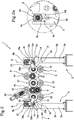
- number 1 indicates an advancement member for fibre material for a carbonization line 100 for the production of carbon fibres.
- the carbonization line is part of a plant for the production of carbon fibre, i.e. A plant typically comprising a first line, or oxidation line, and a second line, subsequent to the first, i.e. the carbonization line 100.
- the carbonization line 100 comprises one or more carbonization ovens 101.
- the carbonization ovens are two arranged in series; more precisely, the carbonization line 100 comprises at least a low-temperature oven 102' and a high-temperature oven 102".
- Each carbonization oven 101 comprises at least one furnace 102 which operates at least at a predetermined temperature and extending along a direction of advance "A" of the fibre material.
- the furnace 102 develops like a substantially box-shaped (or closed) body between an inlet 102a of the fibre material and an outlet 102b of the fibre material.
- inlet and outlet 102a, 102b preferably have an oblong shape (rectangular, substantially horizontal) with vertical extension limited as much as possible without coming into contact with the fibre in order to reduce the dispersion of toxic fumes in the environment.
- the inlet and the outlet are adjustable and/or movable in position by means of sliding bulkheads (not shown) in order to allow an optimization of the positioning of the inlet and outlet 102a, 102b as a function of the height and "attachment" angle of the fibre material.
- a first advancement member 1 is facing the inlet 102a for feeding the fibre material to the furnace 102, while a second advancement member 1 faces the outlet 102b, operationally downstream of the same, to withdraw the fibre material and send it to a furnace or to a subsequent station.
- Each advancement member 1 comprises a support structure 2 extending between two end sections 2a along a direction of advance "A" of the fibre material.
- the support structure 2 has a base 3, preferably equipped with a plurality of ground support portions 3a, or feet.
- the support portions 3a are four, coupled two by two by cross members to stiffen the structure 2.
- the advancement member 1 also comprises a plurality of feed rollers 4, 5 for the fibre material.
- rollers 4, 5 are rotatably associated to the support structure 2.
- the rollers 4, 5 are associated to a portion 3b of the base 3 distal from the support portions 3a.
- rollers 4, 5 are pivoted to an upper portion 3b (or back) of the base 3.
- rollers 4, 5 are arranged parallel to each other in cascade, or in a sequence that defines a preferably rick-rack or serpentine feed path of the fibre material partially wound around them.
- rollers 4, 5 are arranged on a first array 6 and a second array 7.
- Such arrays 6, 7 define a serpentine feed path for the fibre material and comprise an inlet roller 4a and an outlet roller 4b.
- rollers of the first array 6 are defined as first rollers 4 and the rollers of the second array 7 are defined as second rollers 5.
- the arrays can assume a distinct conformation, extending both horizontally and vertically, both with an even or odd number of rollers.
- the arrays 6, 7 extend along said direction of advance "A" with the rollers 4, 5 arranged in succession.
- the first array 6 of rollers has a plurality of rollers arranged in a row at a first height and comprises said inlet roller 4a and said outlet roller 4b.
- the second array 7 of rollers has a plurality of rollers arranged in a row to a second height, higher or lower than said first height, and having a number of rollers 5 which is less than the number of rollers 4 of the first array 6, interposed, with reference to said direction of advance "A", between said inlet rollers 4a and said outlet rollers 4b.
- the first array 6 is a first row and the second array 7 is a second row.
- the first array 6 is located at a height which is higher than the second array 7.
- the number of rollers 6 of the first array (or row) is equal to the number of rollers of the second array 7 (or row) plus one unit.
- the second array 7 of rollers comprises three rollers 5 pivoted to the support structure 2 (preferably with fixed position), while the first array 6 comprises two median rollers 4c, pivoted to the support structure 2 (also preferably with position fixed), and two end rollers movable with respect to the support structure 2 and defining the inlet roller 4a and the outlet roller 4b.
- each roller 4 is rotatably coupled to the structure 2 (in particular to the upper portion 3b) by means of a pair of support elements 8.
- the support elements 8 of the inlet roller 4a and/or of the outlet roller 4b comprise a base 8a integral with the support structure 2 and a ring 8b coupled with the base 8a and having at least one through opening for receiving one end of the respective feed roller 4a, 4b.
- These support elements 8 also comprise adjusting means 8c operatively interposed between the base 8a and the ring 8b, and configured to move the position of the ring 8b relative to the base 8a along a preferably substantially vertical adjustment direction "B".
- the adjusting means 8c are accessible mechanically and/or electronically from the outside of the support element 8 in order to allow an in line adjustment of the position of the ring 8b.
- the adjusting means 8c are of the screw type.
- the adjusting means 8c comprise at least one screw 8d extending along the respective adjustment direction "B" and rotatably coupled (by means of a threaded coupling), respectively to the ring 8b for moving it relative to the base 8a.
- the adjusting means 8c can be operated manually; preferably, each screw is engaged with an actuation nut, selectively usable by the operator for rotating the screw integral with the ring (therefore moving the ring).
- the adjustment means are automated and/or of other nature (e.g., electric motors, linear actuators, spiral pairs, rack and pinion, or other types of known or unknown connections) are also comprised in the spirit of the present invention.
- the adjusting means 8c are provided with at least one locking member 8e configured to constrain the position of the ring 8b with respect to the base 8a, once identified, by the operator, as the optimal one.
- the inlet roller 4a and the outlet roller 4b of the advancement member 1 are motorized.
- the advancement member 1 comprises at least one motor 9 and a transmission assembly 10 operatively interposed between said motor 9, and at least said inlet roller 4a and said outlet roller 4b.
- the transmission assembly 10 comprises a plurality of toothed wheels 12, 13, 15, 18 rotatably coupled to each other to confer to said plurality of rollers 4, 5 a same rotation speed.
- each roller is constrained to a toothed wheel 12, 13, 15, 18; at least one transfer gear 19 is placed between each of these toothed wheels 12, 13, 15, 18.
- the motion transfer gears 19 are interposed between each toothed wheel and the next wheel are at least two.
- the whole transmission assembly 10 extends substantially in a same vertical plane and is secured to a side of the support structure 2.
- the transmission assembly 10 comprises at least one adjustable portion 11 and a fixed portion 17 connected to the support structure 2.
- the adjustable portion 11 is coupled to the inlet roller 4a and/or 4b to the outlet roller configured to track the position of the roller 4a, 4b (or ring 8b of the adjusting means 8) along said adjustment direction "B" by keeping it coupled with the motor 9.
- the fixed portion 17 is coupled to the adjustable portion 11 itself and to the rollers 4, 5, having a fixed position on the support structure 2.
- the transmission assembly 10 is operatively interposed between the motor 9 and each of the rollers of the first array 6 and of the second array 7.
- the adjustable portion 11 coupled to the inlet roller 4a and/or 4b to the outlet roller is configured to track the position of the roller 4a, 4b (i.e. the ring 8b of the adjusting means 8) along said adjustment direction "B" by keeping it coupled with the other rollers 4, 5 of the first array 6 and of the second array 7.
- the transmission assembly 10 comprises two adjustable portions 11, one associated to the inlet roller 4a and one associated to the outlet roller 4b.
- This adjustable portion 11 comprises at least a first toothed wheel 12 coupled with said motor 9, a second toothed wheel 13 rotating integrally with the respective adjustable roller (inlet roller 4a or outlet roller 4b) and at least one connecting arm 14 between said first toothed wheel 12 and said second toothed wheel 13.
- the adjustable portion 11 also comprises a transfer element 15 interposed between the first wheel 12 and the second wheel 13, and configured so as to remain coupled thereto at any position of the inlet roller 4a or outlet roller 4b along the adjustment direction "B".
- the transfer element 15 comprises a third toothed wheel 15a coupled with the first toothed wheel 12 and with the second toothed wheel 13, and having a center of rotation defining an articulation pin 14a of said arm 14.
- Said arm 14 is thus an articulated arm pivoted in said first toothed wheel 12 and said second toothed wheel 13 and has an articulation pin 14a pivoted in said third toothed wheel 15.
- the arm 14 has a first lever 16a extending between the centers of rotation of the first toothed wheel 12 and the third toothed wheel 15 and pivoted thereto and a second lever 16b extending between the centers of rotation of the second toothed wheel 13 and the third toothed wheel 15 and pivoted to them.
- the adjustable portion 11 of the transmission assembly 10 defines a "horse-head" structure.
- the respective inlet roller 4a or outlet roller 4b remains coupled to the transmission assembly 10 and thus motorized.
- the transmission assembly is absent and each roller is associated to a respective motor or gear motor.
- a further alternative involves the use of a single fixed transmission assembly associated to the rollers with given position and a pair of gear motors, each associated directly to the inlet roller or to the outlet roller.
- the invention achieves the intended objects and achieves important advantages.
- support elements adjustable in height for the inlet and outlet rollers of the advancement member allows maximum flexibility in setting and adapting the organ to the specific working conditions of the moment.
Landscapes
- Engineering & Computer Science (AREA)
- General Engineering & Computer Science (AREA)
- Mechanical Engineering (AREA)
- Textile Engineering (AREA)
- Manufacturing & Machinery (AREA)
- Chemical & Material Sciences (AREA)
- Chemical Kinetics & Catalysis (AREA)
- General Chemical & Material Sciences (AREA)
- Inorganic Fibers (AREA)
- Treatment Of Fiber Materials (AREA)
Claims (12)
- Vorschubelement für ein Fasermaterial für eine Karbonisierungsanlage zur Herstellung von Kohlenstofffasern, umfassend:- eine Tragstruktur (2), die sich zwischen zwei Endabschnitten (2a) entlang einer Vorschubrichtung (A) des Fasermaterials erstreckt;- eine Vielzahl an Zuführrollen (4, 5) für das Fasermaterial, die jeweils drehbar mit der Tragstruktur (2) durch ein Paar Tragelemente (8) assoziiert und in Kaskade parallel zueinander angeordnet sind, wobei die Vielzahl an Rollen (4, 5) eine erste (6) und eine zweite Anordnung (7) von Rollen umfasst, die einen Serpentinen-Zuführweg für das Fasermaterial definieren, und eine Einlaufrolle (4a) und eine Auslaufrolle (4b) umfasst; dadurch gekennzeichnet, dass die Tragelemente (8) der Einlassrolle (4a) und/oder der Auslassrolle (4b) umfassen:eine Basis (8a), die fest mit der Tragstruktur (2) verbunden ist,einen Tragring (8b), der mit der Basis (8a) gekoppelt ist und aufweisend mindestens eine Durchgangsöffnung zum Aufnehmen eines Endes der Zuführrolle (4a, 4b) und Einstellmittel (8c), die betriebswirksam zwischen der Basis (8a) und dem Ring (8b) angeordnet sind und so konfiguriert sind, dass sie die Position des Rings (8b) relativ zu der Basis (8a) entlang einer vorzugsweise im Wesentlichen vertikalen Einstellrichtung (B) bewegen.
- Vorschubelement nach Anspruch 1, dadurch gekennzeichnet, dass die Einlassrolle (4a) und die Auslassrolle (4b) motorisiert sind.
- Vorschubelement nach Anspruch 1 oder 2, dadurch gekennzeichnet, dass es mindestens einen Motor (9) und eine Getriebebaugruppe (10) umfasst, die zwischen dem Motor (9) und mindestens der Einlassrolle (4a) und der Auslassrolle (4b) betriebswirksam angeordnet ist.
- Vorschubelement nach Anspruch 3, dadurch gekennzeichnet, dass die Getriebebaugruppe (10) zwischen dem Motor (9) und jeder der Rollen der ersten (6) und der zweiten Anordnung (7) betriebswirksam angeordnet ist.
- Vorschubelement nach Anspruch 3 oder 4, dadurch gekennzeichnet, dass die Getriebebaugruppe (10) mindestens einen einstellbaren Abschnitt (11) umfasst, der mit der Einlassrolle (4a) und/oder der Auslassrolle (4b) gekoppelt ist, wobei der einstellbare Abschnitt (11) konfiguriert ist, um die Position der jeweiligen Einlass- (4a) oder der Auslassrolle (4b) entlang der Einstellrichtung (B) zu verfolgen, während er mit dem Motor (9) und/oder mit den anderen Rollen (4, 5) der ersten (6) und der zweiten Anordnung (7) gekoppelt bleibt.
- Vorschubelement nach Anspruch 5, dadurch gekennzeichnet, dass der einstellbare Abschnitt (11) der Getriebebaugruppe (10) mindestens ein erstes mit dem Motor (9) gekoppeltes Zahnrad (12) und ein zweites mit der Einlassrolle (4a) oder Auslassrolle (4b) gekoppeltes Zahnrad (13) und mindestens einen Verbindungsarm (14) zwischen dem ersten (12) und dem zweiten Zahnrad (13) umfasst.
- Vorschubelement nach Anspruch 6, dadurch gekennzeichnet, dass der einstellbare Abschnitt (11) ein Übertragungselement (15) umfasst, das zwischen dem ersten (12) und dem zweiten Rad (13) angeordnet ist und so konfiguriert ist, dass er an einer beliebigen Position der jeweilige Einlass- (4a) oder Auslassrolle (4b) entlang der Einstellrichtung (B) mit dieser gekoppelt bleibt.
- Vorschubelement nach Anspruch 7, dadurch gekennzeichnet, dass das Übertragungselement (15) ein drittes Zahnrad (15a) umfasst, das mit dem ersten (12) und dem zweiten Zahnrad (13) gekoppelt ist und aufweisend einen Drehpunkt, definierend einen Gelenkstift (14a) des Verbindungsarms (14).
- Vorschubelement nach einem der Ansprüche 5 bis 8, dadurch gekennzeichnet, dass die Getriebebaugruppe (10) einen feststehenden Abschnitt (17) umfasst, der mit der Tragstruktur (2) verbunden ist, die mit dem einstellbaren Abschnitt (11) gekoppelt ist.
- Vorschubelement nach einem der vorhergehenden Ansprüche, dadurch gekennzeichnet, dass die erste Anordnung (6) von Rollen eine Vielzahl an Rollen aufweist, die in einer Reihe in einer ersten Höhe angeordnet sind, und die Einlassrolle (4a) und die Auslassrolle (4b) umfasst; wobei die zweite Anordnung (7) von Rollen eine Vielzahl an Rollen aufweist, die in einer Reihe in einer zweiten Höhe angeordnet sind, die höher oder niedriger als die erste Höhe ist, und aufweisend eine Anzahl von Rollen (5), die geringer als die Anzahl von Rollen (4) der ersten Anordnung (6) ist, die in Bezug auf die Vorschubrichtung (A) zwischen den Einlass- (4a) und den Auslassrollen (4b) angeordnet ist.
- Vorschubelement nach einem der vorhergehenden Ansprüche, dadurch gekennzeichnet, dass:- die zweite Anordnung (7) von Rollen drei Rollen (5) aufweist, die an der Tragstruktur (2) angelenkt sind, und;- die erste Anordnung (6) zwei Mittelrollen (4c), die an der Tragstruktur (2) angelenkt sind, und zwei Endrollen umfasst, die relativ zu der Tragstruktur (2) bewegbar sind und definierend die Einlassrolle (4a) und die Auslassrolle (4b).
- Karbonisierungsofen zur Herstellung von Kohlenstofffasern, umfassend:- ein erstes Vorschubelement (1) nach einem der vorhergehenden Ansprüche;- ein zweites Vorschubelement (1) nach einem der vorhergehenden Ansprüche, das stromabwärts des ersten Vorschubelements (1) betriebswirksam angeordnet und von diesem entlang der Vorschubrichtung (A) beabstandet ist;- einen Ofen (102), der zwischen dem ersten (1) und dem zweiten Vorschubelement (1) angeordnet ist und versehen mit:einem Einlass (102a), der der Auslassrolle (4b) des ersten Vorschubelements (1) zugewandt ist, undeinem Auslass (102b), der der Einlassrolle (4a) des zweiten Vorschubelements (1) zugewandt ist.
Applications Claiming Priority (2)
| Application Number | Priority Date | Filing Date | Title |
|---|---|---|---|
| ITUB2015A005285A ITUB20155285A1 (it) | 2015-10-20 | 2015-10-20 | Organo di avanzamento per materiale in fibra e forno di carbonizzazione per la produzione di fibre di carbonio |
| PCT/IB2016/056152 WO2017068470A1 (en) | 2015-10-20 | 2016-10-14 | Advancement member for fibre material and carbonization furnace for the production of carbon fibre |
Publications (2)
| Publication Number | Publication Date |
|---|---|
| EP3365481A1 EP3365481A1 (de) | 2018-08-29 |
| EP3365481B1 true EP3365481B1 (de) | 2019-06-26 |
Family
ID=55273418
Family Applications (1)
| Application Number | Title | Priority Date | Filing Date |
|---|---|---|---|
| EP16801567.5A Active EP3365481B1 (de) | 2015-10-20 | 2016-10-14 | Vorschubelement für fasermaterial und karbonisierungsofen zur herstellung von kohlenstofffasern |
Country Status (6)
| Country | Link |
|---|---|
| US (1) | US10724155B2 (de) |
| EP (1) | EP3365481B1 (de) |
| KR (1) | KR102606206B1 (de) |
| CN (1) | CN108138382B (de) |
| IT (1) | ITUB20155285A1 (de) |
| WO (1) | WO2017068470A1 (de) |
Family Cites Families (16)
| Publication number | Priority date | Publication date | Assignee | Title |
|---|---|---|---|---|
| US1923183A (en) * | 1932-01-26 | 1933-08-22 | Hans J Blum | Filament spinning apparatus |
| US2035312A (en) * | 1933-07-27 | 1936-03-24 | Herbert C Greer | Continuous strip annealing furnace |
| GB1168619A (en) * | 1966-06-28 | 1969-10-29 | Nat Res Dev | The Production of Carbon Fibres. |
| US3504954A (en) * | 1968-02-29 | 1970-04-07 | Ferro Corp | Bearing support plate |
| JPS516245B2 (de) * | 1972-08-07 | 1976-02-26 | ||
| GB2168966B (en) * | 1984-11-14 | 1988-09-01 | Toho Beslon Co | High-strength carbonaceous fiber |
| JPH082820A (ja) * | 1994-06-20 | 1996-01-09 | Nippon Steel Corp | 糸条ガイド方法およびその装置 |
| DE19927897A1 (de) * | 1999-06-18 | 2000-12-21 | Kampf Gmbh & Co Maschf | Kontakt- oder Transportwalze mit einstellbarer Biegung |
| JP2001020140A (ja) * | 1999-07-06 | 2001-01-23 | Mitsubishi Rayon Co Ltd | 炭素繊維前駆体の駆動装置 |
| CN1918330B (zh) * | 2004-02-13 | 2010-11-10 | 三菱丽阳株式会社 | 碳纤维前驱体纤维束、其制造方法及制造装置以及碳纤维及其制造方法 |
| CN201034148Y (zh) * | 2006-12-29 | 2008-03-12 | 张兵 | 湿巾机传动装置 |
| US8007276B2 (en) * | 2008-04-07 | 2011-08-30 | Despatch Industries Limited | Fiber treatment oven with adjustable gates |
| TWI432621B (zh) * | 2008-04-18 | 2014-04-01 | Mitsubishi Rayon Co | 碳纖維織條的製造裝置以及製造方法 |
| CN102505190A (zh) * | 2011-10-27 | 2012-06-20 | 北京化工大学 | 一种通过控制张力制备高性能碳纤维的方法 |
| CN104214277A (zh) * | 2013-05-31 | 2014-12-17 | 青岛华世洁环保科技有限公司 | 用于萃取槽传动装置的齿轮结构 |
| CN204281923U (zh) * | 2014-12-03 | 2015-04-22 | 荣成复合材料有限公司 | 一种碳纤维定位装置 |
-
2015
- 2015-10-20 IT ITUB2015A005285A patent/ITUB20155285A1/it unknown
-
2016
- 2016-10-14 KR KR1020187008258A patent/KR102606206B1/ko active Active
- 2016-10-14 WO PCT/IB2016/056152 patent/WO2017068470A1/en not_active Ceased
- 2016-10-14 EP EP16801567.5A patent/EP3365481B1/de active Active
- 2016-10-14 CN CN201680060864.XA patent/CN108138382B/zh active Active
- 2016-10-14 US US15/761,948 patent/US10724155B2/en active Active
Also Published As
| Publication number | Publication date |
|---|---|
| WO2017068470A1 (en) | 2017-04-27 |
| EP3365481A1 (de) | 2018-08-29 |
| ITUB20155285A1 (it) | 2017-04-20 |
| US10724155B2 (en) | 2020-07-28 |
| CN108138382B (zh) | 2021-08-06 |
| KR20180071252A (ko) | 2018-06-27 |
| KR102606206B1 (ko) | 2023-11-24 |
| CN108138382A (zh) | 2018-06-08 |
| US20180266019A1 (en) | 2018-09-20 |
Similar Documents
| Publication | Publication Date | Title |
|---|---|---|
| EP3159562B1 (de) | Karbonisierungslinie zur kohlenfaserherstellung mit stützelement für eine vorschubwalze und vorschubwalze für einen faserstoff, und verfahren zur neigungseinstellung der vorschubwalze | |
| AT515201B1 (de) | Vorrichtung zum Fördern von langgestreckten Gegenständen | |
| CN207016970U (zh) | 一种针刺密度均匀的碳纤维制品针刺机 | |
| DE102015107394B4 (de) | Effektor, Vorrichtung und Verfahren zum Aufnehmen, Handhaben und/oder Ablegen von textilen Strukturen | |
| US10307812B2 (en) | Transfer device for a workpiece | |
| CN106535737A (zh) | 处置器具驱动装置 | |
| CN215643859U (zh) | 一种用于对线束端部进行热缩的履带式设备 | |
| RU2399592C2 (ru) | Устройство для гнутья листа стекла, способ и получаемый гнутый лист стекла | |
| US10724155B2 (en) | Advancement member for fiber material and carbonization furnace for the production of carbon fiber | |
| DE2434612A1 (de) | Verfahren und vorrichtung zur bearbeitung warmer glastafeln | |
| JP7590991B2 (ja) | 縦収縮を伴うフィルム延伸設備の戻り収縮およびチェーンテンショナ | |
| CN106978660B (zh) | 分条整经轴和并轴装置的筒子架 | |
| DE102007001707A1 (de) | Thermische Absetzgerätvorrichtung | |
| DK2776185T3 (en) | Pulling device for metal products, such as bars, round pieces or metal wire | |
| CN109179979A (zh) | 辊道绳半自动缠绕机 | |
| EP1147876A1 (de) | Vorrichtung und Verfahren zum Querrecken eines Filmstreifens aus einem Kunststoffmaterial | |
| KR101232265B1 (ko) | 링크부재를 이용한 산업용 로봇 핑거장치 | |
| CN110352125B (zh) | 薄膜拉伸设备 | |
| DE102015013618A1 (de) | Spinn- oder Zwirnmaschine mit hubbewegbarer Spindelbank | |
| CN224185356U (zh) | 一种饲料堆叠用抓取机构 | |
| EP4065352B1 (de) | Pultrusionsverfahren und pultrusionsvorrichtung zur herstellung gekrümmter verbundprofile | |
| DE102016109381B4 (de) | System umfassend einen Kettenförderer mit Justierstation und eine Behandlungseinrichtung | |
| KR20100009315U (ko) | 자동차 판스프링고정용 유자형 볼트제조기의 소재이송장치 | |
| CN119036493A (zh) | 一种用于五金产品制造的夹取机械手 | |
| DE202014004231U1 (de) | Transfervorrichtung |
Legal Events
| Date | Code | Title | Description |
|---|---|---|---|
| STAA | Information on the status of an ep patent application or granted ep patent |
Free format text: STATUS: UNKNOWN |
|
| STAA | Information on the status of an ep patent application or granted ep patent |
Free format text: STATUS: THE INTERNATIONAL PUBLICATION HAS BEEN MADE |
|
| PUAI | Public reference made under article 153(3) epc to a published international application that has entered the european phase |
Free format text: ORIGINAL CODE: 0009012 |
|
| STAA | Information on the status of an ep patent application or granted ep patent |
Free format text: STATUS: REQUEST FOR EXAMINATION WAS MADE |
|
| 17P | Request for examination filed |
Effective date: 20180314 |
|
| AK | Designated contracting states |
Kind code of ref document: A1 Designated state(s): AL AT BE BG CH CY CZ DE DK EE ES FI FR GB GR HR HU IE IS IT LI LT LU LV MC MK MT NL NO PL PT RO RS SE SI SK SM TR |
|
| AX | Request for extension of the european patent |
Extension state: BA ME |
|
| DAV | Request for validation of the european patent (deleted) | ||
| DAX | Request for extension of the european patent (deleted) | ||
| GRAP | Despatch of communication of intention to grant a patent |
Free format text: ORIGINAL CODE: EPIDOSNIGR1 |
|
| STAA | Information on the status of an ep patent application or granted ep patent |
Free format text: STATUS: GRANT OF PATENT IS INTENDED |
|
| INTG | Intention to grant announced |
Effective date: 20190205 |
|
| GRAS | Grant fee paid |
Free format text: ORIGINAL CODE: EPIDOSNIGR3 |
|
| GRAA | (expected) grant |
Free format text: ORIGINAL CODE: 0009210 |
|
| STAA | Information on the status of an ep patent application or granted ep patent |
Free format text: STATUS: THE PATENT HAS BEEN GRANTED |
|
| AK | Designated contracting states |
Kind code of ref document: B1 Designated state(s): AL AT BE BG CH CY CZ DE DK EE ES FI FR GB GR HR HU IE IS IT LI LT LU LV MC MK MT NL NO PL PT RO RS SE SI SK SM TR |
|
| REG | Reference to a national code |
Ref country code: GB Ref legal event code: FG4D |
|
| REG | Reference to a national code |
Ref country code: CH Ref legal event code: EP |
|
| REG | Reference to a national code |
Ref country code: AT Ref legal event code: REF Ref document number: 1148384 Country of ref document: AT Kind code of ref document: T Effective date: 20190715 |
|
| REG | Reference to a national code |
Ref country code: IE Ref legal event code: FG4D |
|
| REG | Reference to a national code |
Ref country code: DE Ref legal event code: R096 Ref document number: 602016016053 Country of ref document: DE |
|
| REG | Reference to a national code |
Ref country code: NL Ref legal event code: MP Effective date: 20190626 |
|
| PG25 | Lapsed in a contracting state [announced via postgrant information from national office to epo] |
Ref country code: AL Free format text: LAPSE BECAUSE OF FAILURE TO SUBMIT A TRANSLATION OF THE DESCRIPTION OR TO PAY THE FEE WITHIN THE PRESCRIBED TIME-LIMIT Effective date: 20190626 Ref country code: FI Free format text: LAPSE BECAUSE OF FAILURE TO SUBMIT A TRANSLATION OF THE DESCRIPTION OR TO PAY THE FEE WITHIN THE PRESCRIBED TIME-LIMIT Effective date: 20190626 Ref country code: LT Free format text: LAPSE BECAUSE OF FAILURE TO SUBMIT A TRANSLATION OF THE DESCRIPTION OR TO PAY THE FEE WITHIN THE PRESCRIBED TIME-LIMIT Effective date: 20190626 Ref country code: SE Free format text: LAPSE BECAUSE OF FAILURE TO SUBMIT A TRANSLATION OF THE DESCRIPTION OR TO PAY THE FEE WITHIN THE PRESCRIBED TIME-LIMIT Effective date: 20190626 Ref country code: NO Free format text: LAPSE BECAUSE OF FAILURE TO SUBMIT A TRANSLATION OF THE DESCRIPTION OR TO PAY THE FEE WITHIN THE PRESCRIBED TIME-LIMIT Effective date: 20190926 Ref country code: HR Free format text: LAPSE BECAUSE OF FAILURE TO SUBMIT A TRANSLATION OF THE DESCRIPTION OR TO PAY THE FEE WITHIN THE PRESCRIBED TIME-LIMIT Effective date: 20190626 |
|
| REG | Reference to a national code |
Ref country code: LT Ref legal event code: MG4D |
|
| PG25 | Lapsed in a contracting state [announced via postgrant information from national office to epo] |
Ref country code: LV Free format text: LAPSE BECAUSE OF FAILURE TO SUBMIT A TRANSLATION OF THE DESCRIPTION OR TO PAY THE FEE WITHIN THE PRESCRIBED TIME-LIMIT Effective date: 20190626 Ref country code: BG Free format text: LAPSE BECAUSE OF FAILURE TO SUBMIT A TRANSLATION OF THE DESCRIPTION OR TO PAY THE FEE WITHIN THE PRESCRIBED TIME-LIMIT Effective date: 20190926 Ref country code: GR Free format text: LAPSE BECAUSE OF FAILURE TO SUBMIT A TRANSLATION OF THE DESCRIPTION OR TO PAY THE FEE WITHIN THE PRESCRIBED TIME-LIMIT Effective date: 20190927 Ref country code: RS Free format text: LAPSE BECAUSE OF FAILURE TO SUBMIT A TRANSLATION OF THE DESCRIPTION OR TO PAY THE FEE WITHIN THE PRESCRIBED TIME-LIMIT Effective date: 20190626 |
|
| REG | Reference to a national code |
Ref country code: AT Ref legal event code: MK05 Ref document number: 1148384 Country of ref document: AT Kind code of ref document: T Effective date: 20190626 |
|
| PG25 | Lapsed in a contracting state [announced via postgrant information from national office to epo] |
Ref country code: PT Free format text: LAPSE BECAUSE OF FAILURE TO SUBMIT A TRANSLATION OF THE DESCRIPTION OR TO PAY THE FEE WITHIN THE PRESCRIBED TIME-LIMIT Effective date: 20191028 Ref country code: RO Free format text: LAPSE BECAUSE OF FAILURE TO SUBMIT A TRANSLATION OF THE DESCRIPTION OR TO PAY THE FEE WITHIN THE PRESCRIBED TIME-LIMIT Effective date: 20190626 Ref country code: AT Free format text: LAPSE BECAUSE OF FAILURE TO SUBMIT A TRANSLATION OF THE DESCRIPTION OR TO PAY THE FEE WITHIN THE PRESCRIBED TIME-LIMIT Effective date: 20190626 Ref country code: CZ Free format text: LAPSE BECAUSE OF FAILURE TO SUBMIT A TRANSLATION OF THE DESCRIPTION OR TO PAY THE FEE WITHIN THE PRESCRIBED TIME-LIMIT Effective date: 20190626 Ref country code: NL Free format text: LAPSE BECAUSE OF FAILURE TO SUBMIT A TRANSLATION OF THE DESCRIPTION OR TO PAY THE FEE WITHIN THE PRESCRIBED TIME-LIMIT Effective date: 20190626 Ref country code: EE Free format text: LAPSE BECAUSE OF FAILURE TO SUBMIT A TRANSLATION OF THE DESCRIPTION OR TO PAY THE FEE WITHIN THE PRESCRIBED TIME-LIMIT Effective date: 20190626 Ref country code: SK Free format text: LAPSE BECAUSE OF FAILURE TO SUBMIT A TRANSLATION OF THE DESCRIPTION OR TO PAY THE FEE WITHIN THE PRESCRIBED TIME-LIMIT Effective date: 20190626 |
|
| PG25 | Lapsed in a contracting state [announced via postgrant information from national office to epo] |
Ref country code: ES Free format text: LAPSE BECAUSE OF FAILURE TO SUBMIT A TRANSLATION OF THE DESCRIPTION OR TO PAY THE FEE WITHIN THE PRESCRIBED TIME-LIMIT Effective date: 20190626 Ref country code: IT Free format text: LAPSE BECAUSE OF FAILURE TO SUBMIT A TRANSLATION OF THE DESCRIPTION OR TO PAY THE FEE WITHIN THE PRESCRIBED TIME-LIMIT Effective date: 20190626 Ref country code: IS Free format text: LAPSE BECAUSE OF FAILURE TO SUBMIT A TRANSLATION OF THE DESCRIPTION OR TO PAY THE FEE WITHIN THE PRESCRIBED TIME-LIMIT Effective date: 20191026 Ref country code: SM Free format text: LAPSE BECAUSE OF FAILURE TO SUBMIT A TRANSLATION OF THE DESCRIPTION OR TO PAY THE FEE WITHIN THE PRESCRIBED TIME-LIMIT Effective date: 20190626 |
|
| PG25 | Lapsed in a contracting state [announced via postgrant information from national office to epo] |
Ref country code: TR Free format text: LAPSE BECAUSE OF FAILURE TO SUBMIT A TRANSLATION OF THE DESCRIPTION OR TO PAY THE FEE WITHIN THE PRESCRIBED TIME-LIMIT Effective date: 20190626 |
|
| PG25 | Lapsed in a contracting state [announced via postgrant information from national office to epo] |
Ref country code: DK Free format text: LAPSE BECAUSE OF FAILURE TO SUBMIT A TRANSLATION OF THE DESCRIPTION OR TO PAY THE FEE WITHIN THE PRESCRIBED TIME-LIMIT Effective date: 20190626 Ref country code: PL Free format text: LAPSE BECAUSE OF FAILURE TO SUBMIT A TRANSLATION OF THE DESCRIPTION OR TO PAY THE FEE WITHIN THE PRESCRIBED TIME-LIMIT Effective date: 20190626 |
|
| PG25 | Lapsed in a contracting state [announced via postgrant information from national office to epo] |
Ref country code: IS Free format text: LAPSE BECAUSE OF FAILURE TO SUBMIT A TRANSLATION OF THE DESCRIPTION OR TO PAY THE FEE WITHIN THE PRESCRIBED TIME-LIMIT Effective date: 20200320 Ref country code: MC Free format text: LAPSE BECAUSE OF FAILURE TO SUBMIT A TRANSLATION OF THE DESCRIPTION OR TO PAY THE FEE WITHIN THE PRESCRIBED TIME-LIMIT Effective date: 20190626 |
|
| REG | Reference to a national code |
Ref country code: CH Ref legal event code: PL |
|
| REG | Reference to a national code |
Ref country code: DE Ref legal event code: R097 Ref document number: 602016016053 Country of ref document: DE |
|
| PLBE | No opposition filed within time limit |
Free format text: ORIGINAL CODE: 0009261 |
|
| STAA | Information on the status of an ep patent application or granted ep patent |
Free format text: STATUS: NO OPPOSITION FILED WITHIN TIME LIMIT |
|
| PG2D | Information on lapse in contracting state deleted |
Ref country code: IS |
|
| PG25 | Lapsed in a contracting state [announced via postgrant information from national office to epo] |
Ref country code: LU Free format text: LAPSE BECAUSE OF NON-PAYMENT OF DUE FEES Effective date: 20191014 Ref country code: LI Free format text: LAPSE BECAUSE OF NON-PAYMENT OF DUE FEES Effective date: 20191031 Ref country code: CH Free format text: LAPSE BECAUSE OF NON-PAYMENT OF DUE FEES Effective date: 20191031 |
|
| 26N | No opposition filed |
Effective date: 20200603 |
|
| REG | Reference to a national code |
Ref country code: BE Ref legal event code: MM Effective date: 20191031 |
|
| PG25 | Lapsed in a contracting state [announced via postgrant information from national office to epo] |
Ref country code: BE Free format text: LAPSE BECAUSE OF NON-PAYMENT OF DUE FEES Effective date: 20191031 Ref country code: SI Free format text: LAPSE BECAUSE OF FAILURE TO SUBMIT A TRANSLATION OF THE DESCRIPTION OR TO PAY THE FEE WITHIN THE PRESCRIBED TIME-LIMIT Effective date: 20190626 |
|
| PG25 | Lapsed in a contracting state [announced via postgrant information from national office to epo] |
Ref country code: IE Free format text: LAPSE BECAUSE OF NON-PAYMENT OF DUE FEES Effective date: 20191014 |
|
| PG25 | Lapsed in a contracting state [announced via postgrant information from national office to epo] |
Ref country code: CY Free format text: LAPSE BECAUSE OF FAILURE TO SUBMIT A TRANSLATION OF THE DESCRIPTION OR TO PAY THE FEE WITHIN THE PRESCRIBED TIME-LIMIT Effective date: 20190626 |
|
| GBPC | Gb: european patent ceased through non-payment of renewal fee |
Effective date: 20201014 |
|
| PG25 | Lapsed in a contracting state [announced via postgrant information from national office to epo] |
Ref country code: MT Free format text: LAPSE BECAUSE OF FAILURE TO SUBMIT A TRANSLATION OF THE DESCRIPTION OR TO PAY THE FEE WITHIN THE PRESCRIBED TIME-LIMIT Effective date: 20190626 Ref country code: HU Free format text: LAPSE BECAUSE OF FAILURE TO SUBMIT A TRANSLATION OF THE DESCRIPTION OR TO PAY THE FEE WITHIN THE PRESCRIBED TIME-LIMIT; INVALID AB INITIO Effective date: 20161014 |
|
| PG25 | Lapsed in a contracting state [announced via postgrant information from national office to epo] |
Ref country code: GB Free format text: LAPSE BECAUSE OF NON-PAYMENT OF DUE FEES Effective date: 20201014 |
|
| PG25 | Lapsed in a contracting state [announced via postgrant information from national office to epo] |
Ref country code: MK Free format text: LAPSE BECAUSE OF FAILURE TO SUBMIT A TRANSLATION OF THE DESCRIPTION OR TO PAY THE FEE WITHIN THE PRESCRIBED TIME-LIMIT Effective date: 20190626 |
|
| P01 | Opt-out of the competence of the unified patent court (upc) registered |
Effective date: 20230520 |
|
| PGFP | Annual fee paid to national office [announced via postgrant information from national office to epo] |
Ref country code: DE Payment date: 20251028 Year of fee payment: 10 |
|
| PGFP | Annual fee paid to national office [announced via postgrant information from national office to epo] |
Ref country code: FR Payment date: 20251027 Year of fee payment: 10 |