EP3364103A1 - Module lumineux, par exemple pour éclairer un composant extérieur d'un véhicule - Google Patents
Module lumineux, par exemple pour éclairer un composant extérieur d'un véhicule Download PDFInfo
- Publication number
- EP3364103A1 EP3364103A1 EP17157174.8A EP17157174A EP3364103A1 EP 3364103 A1 EP3364103 A1 EP 3364103A1 EP 17157174 A EP17157174 A EP 17157174A EP 3364103 A1 EP3364103 A1 EP 3364103A1
- Authority
- EP
- European Patent Office
- Prior art keywords
- optical fiber
- light module
- reflector
- light
- light source
- Prior art date
- Legal status (The legal status is an assumption and is not a legal conclusion. Google has not performed a legal analysis and makes no representation as to the accuracy of the status listed.)
- Withdrawn
Links
Images


Classifications
-
- F—MECHANICAL ENGINEERING; LIGHTING; HEATING; WEAPONS; BLASTING
- F21—LIGHTING
- F21S—NON-PORTABLE LIGHTING DEVICES; SYSTEMS THEREOF; VEHICLE LIGHTING DEVICES SPECIALLY ADAPTED FOR VEHICLE EXTERIORS
- F21S8/00—Lighting devices intended for fixed installation
-
- B—PERFORMING OPERATIONS; TRANSPORTING
- B60—VEHICLES IN GENERAL
- B60Q—ARRANGEMENT OF SIGNALLING OR LIGHTING DEVICES, THE MOUNTING OR SUPPORTING THEREOF OR CIRCUITS THEREFOR, FOR VEHICLES IN GENERAL
- B60Q1/00—Arrangement of optical signalling or lighting devices, the mounting or supporting thereof or circuits therefor
- B60Q1/26—Arrangement of optical signalling or lighting devices, the mounting or supporting thereof or circuits therefor the devices being primarily intended to indicate the vehicle, or parts thereof, or to give signals, to other traffic
- B60Q1/2615—Arrangement of optical signalling or lighting devices, the mounting or supporting thereof or circuits therefor the devices being primarily intended to indicate the vehicle, or parts thereof, or to give signals, to other traffic mounted on the vehicle body, e.g. with magnets
-
- G—PHYSICS
- G02—OPTICS
- G02B—OPTICAL ELEMENTS, SYSTEMS OR APPARATUS
- G02B6/00—Light guides; Structural details of arrangements comprising light guides and other optical elements, e.g. couplings
- G02B6/0001—Light guides; Structural details of arrangements comprising light guides and other optical elements, e.g. couplings specially adapted for lighting devices or systems
- G02B6/0005—Light guides; Structural details of arrangements comprising light guides and other optical elements, e.g. couplings specially adapted for lighting devices or systems the light guides being of the fibre type
- G02B6/001—Light guides; Structural details of arrangements comprising light guides and other optical elements, e.g. couplings specially adapted for lighting devices or systems the light guides being of the fibre type the light being emitted along at least a portion of the lateral surface of the fibre
-
- F—MECHANICAL ENGINEERING; LIGHTING; HEATING; WEAPONS; BLASTING
- F21—LIGHTING
- F21V—FUNCTIONAL FEATURES OR DETAILS OF LIGHTING DEVICES OR SYSTEMS THEREOF; STRUCTURAL COMBINATIONS OF LIGHTING DEVICES WITH OTHER ARTICLES, NOT OTHERWISE PROVIDED FOR
- F21V2200/00—Use of light guides, e.g. fibre optic devices, in lighting devices or systems
- F21V2200/10—Use of light guides, e.g. fibre optic devices, in lighting devices or systems of light guides of the optical fibres type
-
- F—MECHANICAL ENGINEERING; LIGHTING; HEATING; WEAPONS; BLASTING
- F21—LIGHTING
- F21W—INDEXING SCHEME ASSOCIATED WITH SUBCLASSES F21K, F21L, F21S and F21V, RELATING TO USES OR APPLICATIONS OF LIGHTING DEVICES OR SYSTEMS
- F21W2103/00—Exterior vehicle lighting devices for signalling purposes
- F21W2103/15—Side marker lights
-
- F—MECHANICAL ENGINEERING; LIGHTING; HEATING; WEAPONS; BLASTING
- F21—LIGHTING
- F21Y—INDEXING SCHEME ASSOCIATED WITH SUBCLASSES F21K, F21L, F21S and F21V, RELATING TO THE FORM OR THE KIND OF THE LIGHT SOURCES OR OF THE COLOUR OF THE LIGHT EMITTED
- F21Y2115/00—Light-generating elements of semiconductor light sources
- F21Y2115/10—Light-emitting diodes [LED]
-
- G—PHYSICS
- G02—OPTICS
- G02B—OPTICAL ELEMENTS, SYSTEMS OR APPARATUS
- G02B6/00—Light guides; Structural details of arrangements comprising light guides and other optical elements, e.g. couplings
- G02B6/24—Coupling light guides
- G02B6/42—Coupling light guides with opto-electronic elements
- G02B6/4201—Packages, e.g. shape, construction, internal or external details
Definitions
- the invention concerns a light module comprising a light source, an optical fiber and a reflector.
- the light module can be configured for illuminating an outer component of a vehicle.
- the outer components can be strips extending along the profile of the vehicle body, such as strips mounted around lateral doors, rear trunk and/or rear windshield.
- the illumination can be activated in specific conditions, such as braking, doors locking, night detection, or manual control from the dashboard.
- the illumination can be activated with a specific program, such as intermittent lighting with a predetermined pattern and at a predetermined tempo, or permanent lighting in darkness.
- automotive lighting devices are disclosed in documents WO2006086563 , WO2015154972 and WO2016112897 .
- the aim of the invention is to provide an improved light module.
- the invention concerns a light module, comprising: a light source configured for emitting an illumination beam; and an optical fiber guiding the illumination beam between a first end facing the light source and a second end opposite the light source.
- the light module further includes a reflector positioned at the second end of the optical fiber and reflecting the illumination beam back from the second end toward the first end of the optical fiber.
- the reflector minimises the loss of beam energy to be compensated near the second end of the optical fiber.
- the overall illumination and visual aspect provided along the optical fiber are improved.
- the reflector is cheap and simple to implement.
- such a light module may incorporate one or several of the following features:
- Figure 1 shows an optical fiber 80 extending along a longitudinal axis A between a first end 81 and a second end 82.
- Fiber 80 has a core 83 surrounded by a sheath 84.
- a light beam B1 is transmitted along core 83 and regularly reflected on the inner surface of sheath 84.
- Light beam B1 is partly refracted each time it is reflected, resulting in light beams B2 transmitted through sheath 84 outside fiber 80. Under those conditions, energy of each inner beam B1 and outer beams B2 decreases from end 81 toward end 82.
- Figure 2 shows a light module 10 comprising a housing 20, a printed circuit board 50, a light source 60 and a light guide 70.
- Light source 60 is mounted on PCB 50 and configured for emitting an illumination beam B.
- Light guide 70 includes optical fiber 80.
- Beam B enters fiber 80 via its first end 81 and is transmitted as beams B1 and B2, as explained here-above regarding figure 1 .
- Beam B1 escapes from fiber 80 at its end 82. Beams B2 are represented with decreasing energy from end 81 toward end 82 on figure 2 .
- Figure 3 shows the intensity I of illumination emitted by optical fiber 80 along its length L, in the light module 10 of figure 2 .
- a maximal intensity Imax can be observed when fiber 80 goes out of cover 20.
- a minimal intensity can be observed near end 82 due to decreasing energy of beams B2, with a slight increase due to beam B1 escaping fiber 80 at end 82.
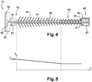
- Figure 4 shows a light module 10 according to the invention, comprising a reflector 90 positioned at end 82 of fiber 80.
- Reflector 90 is designed to reflect beam B1 back from end 82 toward end 81 of fiber 80.
- Reflector 90 has an inner space 91 receiving end 82 of fiber 80.
- Reflector 90 has a concave reflecting surface 92 disposed inside space 91 and designed to reflect beam B1.
- Reflector 90 has an entry opening 93 formed facing surface 92 and designed for inserting end 82 into space 91.
- Reflector 90 can be secured to fiber 80 by any suitable means, for example by force-fitting and/or gluing or welding.
- Opening 93 may have an inner diameter inferior to an outer diameter of fiber 80 at end 82, which is then inserted into opening 93 by force-fitting. Alternately, opening 93 may have an inner diameter equal or superior to an outer diameter of fiber 80 at end 82.
- Reflecting surface 92 can receive end 82 in abutment contact, ensuring that beam B1 is fully reflected back toward end 81.
- a gap can be provided between end 82 and reflecting surface 92, designed with a shape ensuring that beam B1 is fully or mostly reflected toward end 81.
- Figure 5 shows the intensity I of illumination emitted by optical fiber 80 along its length L, in the light module 10 of figure 4 .
- a maximal intensity Imax can be observed when fiber 80 goes out of cover 20. Since beam B1 is reflected by reflector 90 from end 82 toward end 81, more beams B2 are transmitted outside fiber 80 in an end area 86 near end 82. Thus, the minimal intensity observed in end area 86 is higher and better distributed on figure 5 than on figure 3 .
- reflector 90 Thanks to reflector 90, the loss of beam energy is compensated in end area 86. Consequently, the overall illumination and visual aspect provided along fiber 80 are improved.
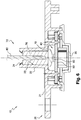
- FIGS 6 and 7 show a second embodiment of the invention.
- elements similar to the first embodiment have the same references and work in the same way. Only the differences with respect to the first embodiment are described hereafter.
- the light module 10 is more detailed and the reflecting surface 92 has a plane shape.
- Module 10 is designed for illuminating an outer component of a vehicle.
- Module 10 comprises a housing 20, a cover 30, a printed circuit board 50, a light source 60 and a light guide 70.
- Housing 20 and cover 30 delimit a watertight inner space 40 between them.
- Space 40 receives PCB 50, on which source 60 is mounted.
- Guide 70 is mounted in housing 20, facing source 60.
- Housing 20 is designed for fastening module 10 to vehicle 1, preferably directly to the outer component. Housing 20 is also designed for receiving guide 70, PCB 50, then cover 30 to close space 40.
- Housing 20 comprises a main body 21 shaped has an elongated plate.
- Housing 20 comprises a protrusion 22 formed on the outer side of body 21.
- Protrusion 22 has a tubular shape and delimits a hollow recess 23 for receiving part of guide 70.
- Recess 23 is open opposite cover 30, such that guide 70 can extend outside module 10.
- the outer end of protrusion 22 is provided with hooks 24 for retaining guide 70 in recess 23.
- Cover 30 is mounted on housing 20 for closing space 40, after PCB 50 has been positioned therein.
- Housing 20 and cover 30 are watertight sealed relative to each other, for example by ultrasonic or laser welding.
- PCB 50 is fastened to housing 20 inside space 40.
- PCB 50 is provided with conductive tracks and connection holes, not shown for simplification purpose.
- PCB 50 is designed for mechanically supporting and electrically connecting electronic components, such as source 60 and system 80.
- Light source 60 is preferably a light-emitting diode.
- Source 60 is configured for emitting the illumination beam B, for example within a cone having an apex angle of 100 degrees.
- Source 60 is fixedly mounted on PCB 50.
- source 60 is provided with connection pins inserted in holes of PCB 50.
- Light guide 70 is mounted in housing 20 facing source 60.
- Guide 70 extends at least partly outside space 40 for guiding beam B along component 2.
- Guide 70 comprises an abutment 76, a lens 78, the optical fiber 80 and the reflector 90.
- Fiber 80 extends outside space 40 for guiding beam B along the outer component. Fiber 80 has a diameter of approximately 2 or 3 millimeters. Beam B enters at end 81 and is guided along fiber 80.
- Abutment 76 has a cylindrical shape and is made of a transparent material. End 81 of fiber 80 is integrated inside abutment 76, for example by screwing, clipping or overmolding. Abutment 76 is positioned in recess 23, with hooks 24 in retaining contact with its outer surface.
- Lens 78 is positioned between source 60 and end 81, such that beam B emitted by source 60 is focalized toward end 81.
- lens 78 has a specific convergent shape, entirely focalizing beam B on a focus point 85 located at the precise center of end 81.
- Lens 78 is transparent, while housing 20 and cover 30 are preferably opaque, thus ensuring that beam B it transmitted outside module 10 only through guide 70, more precisely fiber 80.
- light module 10 can be adapted to the specific requirements of the application.
Landscapes
- Physics & Mathematics (AREA)
- Engineering & Computer Science (AREA)
- General Physics & Mathematics (AREA)
- Optics & Photonics (AREA)
- Mechanical Engineering (AREA)
- General Engineering & Computer Science (AREA)
- Optical Couplings Of Light Guides (AREA)
- Non-Portable Lighting Devices Or Systems Thereof (AREA)
- Lighting Device Outwards From Vehicle And Optical Signal (AREA)
Priority Applications (3)
| Application Number | Priority Date | Filing Date | Title |
|---|---|---|---|
| EP17157174.8A EP3364103A1 (fr) | 2017-02-21 | 2017-02-21 | Module lumineux, par exemple pour éclairer un composant extérieur d'un véhicule |
| US15/890,518 US10399482B2 (en) | 2017-02-21 | 2018-02-07 | Light module, by example for illuminating an outer component of a vehicle |
| CN201810151592.5A CN108458279A (zh) | 2017-02-21 | 2018-02-13 | 例如用于照明车辆的外部部件的光模块 |
Applications Claiming Priority (1)
| Application Number | Priority Date | Filing Date | Title |
|---|---|---|---|
| EP17157174.8A EP3364103A1 (fr) | 2017-02-21 | 2017-02-21 | Module lumineux, par exemple pour éclairer un composant extérieur d'un véhicule |
Publications (1)
| Publication Number | Publication Date |
|---|---|
| EP3364103A1 true EP3364103A1 (fr) | 2018-08-22 |
Family
ID=58158847
Family Applications (1)
| Application Number | Title | Priority Date | Filing Date |
|---|---|---|---|
| EP17157174.8A Withdrawn EP3364103A1 (fr) | 2017-02-21 | 2017-02-21 | Module lumineux, par exemple pour éclairer un composant extérieur d'un véhicule |
Country Status (3)
| Country | Link |
|---|---|
| US (1) | US10399482B2 (fr) |
| EP (1) | EP3364103A1 (fr) |
| CN (1) | CN108458279A (fr) |
Families Citing this family (2)
| Publication number | Priority date | Publication date | Assignee | Title |
|---|---|---|---|---|
| CN110088657A (zh) * | 2016-10-21 | 2019-08-02 | 德韧营运有限责任公司 | 用于照亮车辆外部部件的发光模块及其制造方法 |
| US10543812B1 (en) * | 2018-09-28 | 2020-01-28 | Ford Global Technologies, Llc | Vehicle sensor |
Citations (8)
| Publication number | Priority date | Publication date | Assignee | Title |
|---|---|---|---|---|
| US4936663A (en) * | 1988-08-10 | 1990-06-26 | Kei Mori | Light radiator |
| WO2005106899A1 (fr) * | 2004-04-29 | 2005-11-10 | University Of Technology, Sydney | Cable de transmission optiquement traçable pour la transmission de donnees ou d'electricite et conduit traçable |
| WO2006086563A2 (fr) | 2005-02-09 | 2006-08-17 | Dura Automotive Systems | Diode electroluminescente moulee dans un guide de lumiere |
| DE202007014598U1 (de) * | 2007-10-16 | 2009-02-26 | Witte-Velbert Gmbh & Co. Kg | Kennzeichenbeleuchtung |
| US20150016147A1 (en) * | 2013-07-15 | 2015-01-15 | Hon Hai Precision Industry Co., Ltd. | Led tube with light reflective face |
| US20150277034A1 (en) * | 2014-03-24 | 2015-10-01 | Denso Corporation | Fiber optical light guide, attachment member for the same, and lighting device |
| WO2015154972A1 (fr) | 2014-04-08 | 2015-10-15 | Dura Automotive Body & Glass Systems Gmbh | Bande décorative éclairée |
| WO2016112897A1 (fr) | 2015-01-12 | 2016-07-21 | Dura Automotive Body & Glass Systems Gmbh | Baguette décorative éclairée |
Family Cites Families (1)
| Publication number | Priority date | Publication date | Assignee | Title |
|---|---|---|---|---|
| US4885663A (en) * | 1988-03-22 | 1989-12-05 | Lumitex, Inc. | Fiber optic light emitting panel and method of making same |
-
2017
- 2017-02-21 EP EP17157174.8A patent/EP3364103A1/fr not_active Withdrawn
-
2018
- 2018-02-07 US US15/890,518 patent/US10399482B2/en not_active Expired - Fee Related
- 2018-02-13 CN CN201810151592.5A patent/CN108458279A/zh active Pending
Patent Citations (8)
| Publication number | Priority date | Publication date | Assignee | Title |
|---|---|---|---|---|
| US4936663A (en) * | 1988-08-10 | 1990-06-26 | Kei Mori | Light radiator |
| WO2005106899A1 (fr) * | 2004-04-29 | 2005-11-10 | University Of Technology, Sydney | Cable de transmission optiquement traçable pour la transmission de donnees ou d'electricite et conduit traçable |
| WO2006086563A2 (fr) | 2005-02-09 | 2006-08-17 | Dura Automotive Systems | Diode electroluminescente moulee dans un guide de lumiere |
| DE202007014598U1 (de) * | 2007-10-16 | 2009-02-26 | Witte-Velbert Gmbh & Co. Kg | Kennzeichenbeleuchtung |
| US20150016147A1 (en) * | 2013-07-15 | 2015-01-15 | Hon Hai Precision Industry Co., Ltd. | Led tube with light reflective face |
| US20150277034A1 (en) * | 2014-03-24 | 2015-10-01 | Denso Corporation | Fiber optical light guide, attachment member for the same, and lighting device |
| WO2015154972A1 (fr) | 2014-04-08 | 2015-10-15 | Dura Automotive Body & Glass Systems Gmbh | Bande décorative éclairée |
| WO2016112897A1 (fr) | 2015-01-12 | 2016-07-21 | Dura Automotive Body & Glass Systems Gmbh | Baguette décorative éclairée |
Also Published As
| Publication number | Publication date |
|---|---|
| US10399482B2 (en) | 2019-09-03 |
| CN108458279A (zh) | 2018-08-28 |
| US20180236930A1 (en) | 2018-08-23 |
Similar Documents
| Publication | Publication Date | Title |
|---|---|---|
| EP2277741B1 (fr) | Rétroviseur indicateur de signal de changement de direction à guide lumineux | |
| US10036522B2 (en) | Vehicular lamp | |
| EP2353937A1 (fr) | Lampe de véhicule | |
| EP2123514A1 (fr) | Module lumineux pour ensemble de miroir de véhicule et ensemble de miroir de véhicule comprenant le module lumineux | |
| KR20100123892A (ko) | 도어 미러 장치 | |
| JP2006256606A (ja) | 車両、好ましくは自動車の車外バックミラー | |
| RU2627030C2 (ru) | Крышка динамика | |
| US7264383B2 (en) | Lighting element with a light emitting device | |
| US10399482B2 (en) | Light module, by example for illuminating an outer component of a vehicle | |
| KR102116081B1 (ko) | 광원으로부터 오프셋된 발광 요소를 포함하는, 특히 자동차 조명 부품용 조명 시스템 | |
| US20190234582A1 (en) | Light module for illuminating an outer component of a vehicle, and process for manufacturing such light module | |
| US9285093B2 (en) | Self-locating light source module | |
| US11397299B2 (en) | Light module for illuminating an outer component of a vehicle, and process for manufacturing such light module | |
| JP4702278B2 (ja) | 車両用灯具 | |
| JP2016100257A (ja) | 車両用灯具 | |
| JP5407190B2 (ja) | 車両用ドアトリム照明装置 | |
| US11643015B2 (en) | Exterior rearview device for automotive vehicles and kit of parts | |
| US10890727B2 (en) | Light module for illuminating an outer component of a vehicle, and process for manufacturing such light module | |
| CN211526339U (zh) | 外后视镜转向灯、外后视镜及车辆 | |
| US20160107567A1 (en) | Instrument cluster including a pcb mounted light conductor | |
| JP2008162296A (ja) | 車両用灯具 | |
| JP7034750B2 (ja) | 車両用灯具 | |
| KR101863787B1 (ko) | 차량용 램프 | |
| CN114383105A (zh) | 用于车辆的发光模块及包括该发光模块的灯装置 |
Legal Events
| Date | Code | Title | Description |
|---|---|---|---|
| PUAI | Public reference made under article 153(3) epc to a published international application that has entered the european phase |
Free format text: ORIGINAL CODE: 0009012 |
|
| STAA | Information on the status of an ep patent application or granted ep patent |
Free format text: STATUS: THE APPLICATION HAS BEEN PUBLISHED |
|
| AK | Designated contracting states |
Kind code of ref document: A1 Designated state(s): AL AT BE BG CH CY CZ DE DK EE ES FI FR GB GR HR HU IE IS IT LI LT LU LV MC MK MT NL NO PL PT RO RS SE SI SK SM TR |
|
| AX | Request for extension of the european patent |
Extension state: BA ME |
|
| RAP1 | Party data changed (applicant data changed or rights of an application transferred) |
Owner name: DURA OPERATING, LLC |
|
| STAA | Information on the status of an ep patent application or granted ep patent |
Free format text: STATUS: REQUEST FOR EXAMINATION WAS MADE |
|
| 17P | Request for examination filed |
Effective date: 20181226 |
|
| RBV | Designated contracting states (corrected) |
Designated state(s): AL AT BE BG CH CY CZ DE DK EE ES FI FR GB GR HR HU IE IS IT LI LT LU LV MC MK MT NL NO PL PT RO RS SE SI SK SM TR |
|
| STAA | Information on the status of an ep patent application or granted ep patent |
Free format text: STATUS: EXAMINATION IS IN PROGRESS |
|
| 17Q | First examination report despatched |
Effective date: 20200406 |
|
| STAA | Information on the status of an ep patent application or granted ep patent |
Free format text: STATUS: THE APPLICATION IS DEEMED TO BE WITHDRAWN |
|
| 18D | Application deemed to be withdrawn |
Effective date: 20200818 |