EP3364043A1 - Groupe motopompe avec dispositif de purge d'air et de vidange intégré - Google Patents
Groupe motopompe avec dispositif de purge d'air et de vidange intégré Download PDFInfo
- Publication number
- EP3364043A1 EP3364043A1 EP17156907.2A EP17156907A EP3364043A1 EP 3364043 A1 EP3364043 A1 EP 3364043A1 EP 17156907 A EP17156907 A EP 17156907A EP 3364043 A1 EP3364043 A1 EP 3364043A1
- Authority
- EP
- European Patent Office
- Prior art keywords
- connection
- pump unit
- unit according
- valve element
- emptying
- Prior art date
- Legal status (The legal status is an assumption and is not a legal conclusion. Google has not performed a legal analysis and makes no representation as to the accuracy of the status listed.)
- Granted
Links
- 238000013022 venting Methods 0.000 title claims description 6
- 239000007788 liquid Substances 0.000 title description 21
- 238000010926 purge Methods 0.000 title 1
- 238000007789 sealing Methods 0.000 claims description 25
- 238000006073 displacement reaction Methods 0.000 claims description 3
- 230000000630 rising effect Effects 0.000 claims description 2
- 230000002093 peripheral effect Effects 0.000 description 6
- XLYOFNOQVPJJNP-UHFFFAOYSA-N water Substances O XLYOFNOQVPJJNP-UHFFFAOYSA-N 0.000 description 6
- 238000010438 heat treatment Methods 0.000 description 5
- 238000009434 installation Methods 0.000 description 4
- 230000015572 biosynthetic process Effects 0.000 description 2
- 238000005266 casting Methods 0.000 description 2
- 239000012530 fluid Substances 0.000 description 2
- 239000002184 metal Substances 0.000 description 2
- 230000035508 accumulation Effects 0.000 description 1
- 238000009825 accumulation Methods 0.000 description 1
- 238000004378 air conditioning Methods 0.000 description 1
- 230000000712 assembly Effects 0.000 description 1
- 238000000429 assembly Methods 0.000 description 1
- 150000001875 compounds Chemical class 0.000 description 1
- 230000001276 controlling effect Effects 0.000 description 1
- 238000007599 discharging Methods 0.000 description 1
- 230000000694 effects Effects 0.000 description 1
- 230000008014 freezing Effects 0.000 description 1
- 238000007710 freezing Methods 0.000 description 1
- 239000013505 freshwater Substances 0.000 description 1
- 238000004519 manufacturing process Methods 0.000 description 1
- 238000000034 method Methods 0.000 description 1
- 238000005192 partition Methods 0.000 description 1
- 230000001105 regulatory effect Effects 0.000 description 1
- 238000009423 ventilation Methods 0.000 description 1
- 238000004804 winding Methods 0.000 description 1
Images


Classifications
-
- F—MECHANICAL ENGINEERING; LIGHTING; HEATING; WEAPONS; BLASTING
- F04—POSITIVE - DISPLACEMENT MACHINES FOR LIQUIDS; PUMPS FOR LIQUIDS OR ELASTIC FLUIDS
- F04D—NON-POSITIVE-DISPLACEMENT PUMPS
- F04D9/00—Priming; Preventing vapour lock
- F04D9/004—Priming of not self-priming pumps
- F04D9/006—Priming of not self-priming pumps by venting gas or using gas valves
-
- F—MECHANICAL ENGINEERING; LIGHTING; HEATING; WEAPONS; BLASTING
- F04—POSITIVE - DISPLACEMENT MACHINES FOR LIQUIDS; PUMPS FOR LIQUIDS OR ELASTIC FLUIDS
- F04D—NON-POSITIVE-DISPLACEMENT PUMPS
- F04D29/00—Details, component parts, or accessories
- F04D29/40—Casings; Connections of working fluid
- F04D29/42—Casings; Connections of working fluid for radial or helico-centrifugal pumps
- F04D29/426—Casings; Connections of working fluid for radial or helico-centrifugal pumps especially adapted for liquid pumps
- F04D29/4293—Details of fluid inlet or outlet
-
- F—MECHANICAL ENGINEERING; LIGHTING; HEATING; WEAPONS; BLASTING
- F05—INDEXING SCHEMES RELATING TO ENGINES OR PUMPS IN VARIOUS SUBCLASSES OF CLASSES F01-F04
- F05D—INDEXING SCHEME FOR ASPECTS RELATING TO NON-POSITIVE-DISPLACEMENT MACHINES OR ENGINES, GAS-TURBINES OR JET-PROPULSION PLANTS
- F05D2250/00—Geometry
- F05D2250/50—Inlet or outlet
- F05D2250/51—Inlet
-
- F—MECHANICAL ENGINEERING; LIGHTING; HEATING; WEAPONS; BLASTING
- F05—INDEXING SCHEMES RELATING TO ENGINES OR PUMPS IN VARIOUS SUBCLASSES OF CLASSES F01-F04
- F05D—INDEXING SCHEME FOR ASPECTS RELATING TO NON-POSITIVE-DISPLACEMENT MACHINES OR ENGINES, GAS-TURBINES OR JET-PROPULSION PLANTS
- F05D2260/00—Function
- F05D2260/60—Fluid transfer
- F05D2260/602—Drainage
-
- F—MECHANICAL ENGINEERING; LIGHTING; HEATING; WEAPONS; BLASTING
- F05—INDEXING SCHEMES RELATING TO ENGINES OR PUMPS IN VARIOUS SUBCLASSES OF CLASSES F01-F04
- F05D—INDEXING SCHEME FOR ASPECTS RELATING TO NON-POSITIVE-DISPLACEMENT MACHINES OR ENGINES, GAS-TURBINES OR JET-PROPULSION PLANTS
- F05D2260/00—Function
- F05D2260/60—Fluid transfer
- F05D2260/605—Venting into the ambient atmosphere or the like
Definitions
- the invention relates to a pump unit with a pump housing, in which a suction chamber is formed, which has an emptying port.
- the pump unit has a pump housing, which defines the flow paths through the pump unit for a liquid to be conveyed, in particular a heat transfer medium to be conveyed.
- This liquid may in particular be water.
- the pump housing defines a suction chamber, which is located on the input side of the pump unit and in which enters the liquid to be delivered.
- This suction chamber has at least one emptying connection, via which the fluid can be discharged from the suction space and preferably the entire pump unit and the pump unit or the suction space can be emptied. According to the emptying connection is connected to at least two spaced-apart areas in the interior of the suction chamber.
- the emptying connection has a first connection to a region of the suction chamber to be vented, which is located vertically above a bottom region of the suction chamber.
- the area to be deaerated is that area in the interior of the suction space in which air to be removed accumulates.
- the emptying connection has a second connection, which leads from the emptying connection to the bottom region of the suction chamber or connects the emptying connection to the bottom region of the suction chamber or the entire pump housing.
- the suction chamber can be substantially completely emptied, as this opens in the bottom area and this essentially defines the lowest point of the suction chamber at the intended installation position for operation of the pump unit, so that from there substantially all of the liquid from the suction chamber over can drain the emptying connection.
- the first connection to a higher vertical area can be used to vent the suction chamber.
- the vertically higher position also refers to the intended installation position of the pump unit during operation. Air will accumulate inside the suction chamber in the upper area of the suction chamber.
- the second connection is particularly preferably connected both to the bottom region of the suction chamber and to the bottom region of a pressure chamber of the pump housing which is separate from the suction chamber, so that the interior of the entire pump housing can be emptied via this connection.
- a valve device is arranged on or in the emptying connection which is designed such that it has at least two different switching positions, wherein in a first switching position the first connection and in a second switching position at least the second connection is opened.
- both connections can be opened in the second switching position.
- the first switching position thus serves for venting. In this switching position, only the connection to the vertical upper region in the interior of the suction chamber is opened, so that this region can be vented in the manner described above.
- the connection to the bottom region of the suction chamber or of the suction and pressure chamber is opened so that substantially all the liquid from the suction chamber or the pump housing can drain through the emptying connection.
- the valve device also has a rest position in which both connections are closed. This is the position that the valve device has during normal operation of the pump set.
- the first connection preferably opens into a region of the vertically upper end of the suction chamber and more preferably in an upper fourth of the suction chamber.
- the vertical distance of the mouth of the first connection from the upper end of the suction chamber is preferably less than 25%, more preferably less than 10% and even more preferably less than 5% of the total height of the suction chamber in the vertical direction.
- the vertical direction of the suction chamber is that axis of the suction chamber, which extends in the intended operating position of the pump unit in the vertical direction.
- the pump unit is designed as a centrifugal pump unit with at least one rotationally driven impeller.
- the axis of rotation of the impeller preferably in the horizontal direction, so that the vertical extent of the suction chamber, as described above, extends normal to the axis of rotation.
- the centrifugal pump unit may be further preferably designed as a wet-running centrifugal pump unit, d. h., With a wet-running electric drive motor, wherein the stator and rotor are separated by a split pot or a can.
- the first connection opens above a suction mouth of the impeller in the suction chamber. This ensures that air can be removed from the suction chamber before it enters the suction port and would block the delivery through the impeller.
- the pump unit may be part of a hydraulic unit or a hydraulic block, as used for example in compact heating systems.
- a hydraulic Assembly unit integrates all the essential hydraulic components or flow paths of such a heating system and, for example, additionally have one or more valves, a heat exchanger for heating process water, required sensors and connections for fresh water supply and removal and external heating circuits.
- a unit preferably has connections for a heat source such as a primary heat exchanger of a boiler.
- the pump unit preferably has on its pump housing a suction-side connection, which opens into the suction chamber. This can be in the intended installation position, for example, down or even, starting from the axial end face of the pump housing, d. h., Essentially in the horizontal direction, in the preferred mounting position.
- the pump housing preferably has a pressure chamber which, in the case of a centrifugal pump assembly, surrounds the at least one impeller and which has a pressure connection, ie. h., An output-side connection of the pump housing is provided.
- the pressure port may extend in the intended mounting position, for example, upwards or laterally away from the pump housing.
- the first connection is preferably formed by a channel which is formed between a wall of the pump housing, in particular an end wall and a deflector plate inserted into the pump housing, wherein the deflector plate surrounds the suction mouth of the impeller.
- the deflector plate separates the suction chamber from the pressure chamber in the interior of the pump housing.
- the deflector plate has a central opening which engages the suction mouth of the impeller and through which the liquid sucked by the impeller enters the suction mouth.
- a deflector plate is often as a separate Part formed, which is inserted into the pump housing. This is the case in particular if the pump housing, as preferred, is manufactured as a cast component from plastic or metal. In such a case, the deflector plate avoids the formation of undercuts that are difficult or impossible to remove inside the pump housing.
- connection or the channel between the deflector plate and a wall of the pump housing has the advantage that the connection can be made very simple as a channel, since the channel substantially in the casting of the pump housing, if this is formed as a cast component mitgeformt can and can then be closed on a remaining open side by the deflector plate.
- the channel can be formed during casting as an open channel, which is easy to core.
- the channel is preferably delimited by two ribs projecting from an axial end wall of the pump housing.
- the ribs furthermore preferably run essentially parallel to one another and form side walls of the channel.
- the deflector plate comes at least partially against the end wall of the pump housing facing edges of the rib to rest.
- the deflector plate abuts substantially the entire length at the edges of the ribs so that the open side of the channel is closed by the deflector plate. It should be understood that the installation of the deflector plate on the ribs need not be completely sealed. Preferably, however, remaining gaps between the deflector plate and the ribs should be smaller than the opening of the channel at its end, which forms the intended inlet opening in the channel.
- the ribs are integral with the end wall of the pump housing, preferably made of metal or plastic, educated.
- the end wall of the pump housing is the axial end wall, which extends in the case of a centrifugal pump assembly substantially transverse to the axis of rotation of the impeller.
- the wall is that wall which is formed on the impeller opposite axial end of the pump housing.
- the pump housing is preferably designed to be open and is closed by an attached drive motor or its can, when the drive motor, as preferred, is a wet-running electric drive motor.
- the channel extends at least in a direction adjacent to its upper end portion vertically and preferably in the direction of a diameter of the pump housing transverse to the axis of rotation of the impeller.
- the passage in a vertically lower portion is preferably arcuate in the peripheral portion of the central opening in the deflector plate which is engaged with the suction port of the impeller.
- At least one vertically upper side surface of the channel extends in all areas angled to the horizontal and preferably in the vertical direction rising to the upper end of the channel. This prevents the channel from having dead spaces in which air bubbles can accumulate and hold.
- the vertically upper side surface is preferably a side surface of the channel, which extends between the end face of the pump housing and the deflector plate.
- the emptying port is further preferably located on an underside of the pump housing and open towards the bottom. This promotes the drainage of the liquid through the discharge port. Moreover, in many pump assemblies, particularly when used in a hydraulic assembly as described above, it is preferred that all of the essential connections be located at the bottom. Thus, an access or connection region of the pump assembly or the hydraulic assembly may be formed on the underside.
- the valve element is preferably inserted into the emptying connection, in particular inserted from below. More preferably, the valve element is operable from the bottom of the pump unit. This has the advantage that the valve element can be operated from the side to which the outlet of the discharge port is located. In particular, if there is a central connection region of the pump unit or a hydraulic unit, in which the pump unit is integrated, at the bottom, it is expedient to operate from there, the valve element.
- the valve element is in engagement with the emptying connection via a slotted guide, which is embodied such that rotation of the valve element results in a simultaneous axial displacement of the valve element in the emptying connection.
- a slotted guide which is embodied such that rotation of the valve element results in a simultaneous axial displacement of the valve element in the emptying connection.
- at least one essentially helically extending groove can be formed, into which at least one pin engages on the inner circumference of the emptying connection. If now the valve element is rotated, the pin slides in the groove and simultaneously causes an axial movement of the valve element.
- the valve element preferably has sealing surfaces or sealing seats, which are brought into and out of engagement in the axial direction. D.
- Via the slotted guide can then be effected by rotation of the valve element, an axial displacement, which brings the sealing surfaces or sealing seats in and out of engagement to open and close the connections to the discharge port.
- the rotation of the valve element allows easy operation.
- the axial movement favors the engagement and disengagement of the sealing surfaces or sealing seats.
- the valve element closes both the first connection and the second connection in a rest position in the emptying connection.
- the valve element In a first switching position deviating from the rest position, the valve element preferably releases an opening to the first connection. In this switching position thus a connection to the vertical upper portion of the suction chamber is given, so that a vent can be done.
- the valve element In a second switching position deviating from the rest position and the first switching position, the valve element preferably releases an opening to the second connection, which ends in the bottom region of the suction chamber in order to empty the suction chamber. If appropriate, the first connection to the upper region of the suction chamber may also be opened at the same time in this second switching position.
- the valve element can have a first sealing surface which, in the rest position, seals against a valve seat or a wall in the discharge opening is applied and spaced in the first and the second switching position of the valve seat or the wall.
- the opening on this valve seat is opened, which is an opening to the first connection.
- the valve element preferably has a second sealing surface, which rests in the rest position and the first switching position sealingly on a wall of the discharge opening and is spaced in the second switching position of this wall of the discharge opening, thereby releasing a flow path to the second connection to the bottom region of the suction chamber will be to empty this.
- the first and second sealing surfaces are preferably designed as annular sealing surfaces or sealing rings.
- Such sealing rings can be formed for example by O-rings.
- the seal is preferably carried out radially against a circumferentially surrounding inner wall of the discharge opening.
- the disengagement of these annular sealing seats or sealing surfaces of the walls by the axial movement is achieved in that the discharge opening in its interior extends stepwise or stepped circumferential extensions.
- the annular sealing surface is moved by axial movement in the region of a circumferential extension, so that a clearance between the sealing surface and the now radially spaced circumferential extension is provided, through which a flow can pass.
- the described extent extensions do not have to be made in their entirety. Rather, this can also be the case only in a peripheral section.
- the valve element has in its interior an emptying channel, which in the first switching position with the first connection and in the second switching position with the second compound and preferably in the second switching position with both the first and connected to the second connection.
- the emptying channel can open into a hose or line connection to which a drainage line or a drainage hose for discharging the outflowing water or the exiting liquid can be connected.
- the emptying channel opens at the opposite end preferably in a peripheral region of the valve element, based on the linear axis of movement of the valve element.
- the opening in the peripheral region is preferably located between a first and a second sealing surface, as described above.
- the first sealing surface when moved away from the associated valve seat or the surrounding wall, release a first flow path to the opening in the discharge channel, while the second sealing surface, when out of their associated sealing seat or a wall of the emptying port out of engagement occurs to release a second flow path from the second connection to the opening of the discharge channel.
- the valve element is preferably also formed as a plastic injection-molded part and the required seals or sealing surfaces are formed by O-rings, which are inserted into grooves on the outer circumference.
- the required seals or sealing surfaces are formed by O-rings, which are inserted into grooves on the outer circumference.
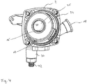
- Fig. 1 and 2 show the exemplary overall structure of a pump unit according to the invention.
- the pump unit has a pump housing 2, which with a stator or motor housing 4 is connected, in which a not shown here in detail electric drive motor is arranged.
- an electronics housing 6 is attached, in which the electrical connections of the drive motor and electronic components for controlling or regulating the drive motor can be arranged.
- a gap pot or gap tube 8 is arranged, which separates a rotor space 10 from a stator space 12 in the interior of the motor housing 4.
- the stator is arranged in a known manner with the electrical windings, while in the rotor chamber 10, the rotor of the electric motor is rotatably mounted.
- the electric motor is thus designed as a wet-running electric motor, in which the rotor chamber 10 is filled with the liquid to be pumped by the pump unit, for example water.
- the pump unit for example water.
- an impeller 14 is arranged, which is rotatably connected to a rotor, which is arranged in the rotor chamber 10, so that the impeller 14 can be driven in rotation by the electric motor.
- the pump housing 2 has a suction connection 16 or suction connection 16 and a pressure connection or discharge connection 18.
- the suction connection 16 opens in the interior of the pump housing into a suction chamber 20, which is separated from the pressure chamber 22 surrounding the impeller 14 by a deflector plate 24.
- the deflector plate 24 thus forms a partition wall between the pressure chamber 22 and the suction chamber 20.
- the deflector plate 24 has a central opening 26, which faces the suction mouth 28 of the impeller 14 or with its peripheral collar with the suction port 28 of the impeller 14 is engaged .
- the impeller 14 rotates and sucks in the region of its suction mouth 28 through the opening 26 liquid from the suction chamber 20 at.
- the liquid then exits the impeller 14 in the pressure chamber 22 on the outer circumference.
- the pressure chamber 22 is with connected to the pressure port 18 through which the pumped liquid exits the pump unit.
- the pump unit according to the invention has on its underside an emptying port 30, which opens into the suction chamber 20 in the interior of the pump housing and branches off from it.
- the emptying port 30 has two functions in the pump according to the invention. On the one hand, it enables the pump housing 2 to be emptied of liquid in its interior. On the other hand, it also allows the ventilation of the suction chamber 20, as will be described below.
- Fig. 3 shows a plan view into the interior of the open pump housing 2 without the deflector plate 24.
- the pump housing 2 is formed in this example as a one-piece cast component, in particular made of plastic. From the pump housing 2 branches off at the outer periphery of the pressure port 18 from. The suction port 16 extends from the axial end face 32 of the pump housing 2 to the outside. From the bottom of the emptying port 30 branches off.
- the directions mentioned relate to the axis of rotation X, which extends in the intended operating position of the pump unit in the horizontal direction. That is, the Fig. 1 and 3 show the position of the pump unit or the pump housing 2, as provided for the operation.
- the arrangement of the pressure port 18 on the side and the arrangement of the discharge port 30 on the underside of the pump housing 2 have the advantage that the top of the pump housing 2 remains free, so that overall the height of the pump housing is reduced, which is advantageous for certain applications.
- the pressure connection 18 could, for example, also be arranged on the upper side of the pump housing 2.
- the emptying connection 30 opens inside the pump housing 2 into a channel 34.
- the emptying connection 30 extends with a tubular section 36 parallel to the diameter axis Y to a certain extent into the interior of the pump housing 2.
- At its inner or upper end of the tubular portion 36 opens into the channel 34.
- the channel 34 is formed by two mutually parallel ribs 38.
- the ribs 38 are formed integrally with the pump housing 2 and extend away from the rear end wall 32.
- the ribs 36 define the channel 34 and thus form a groove, which is open to the side facing away from the end face 32 side. This page is, as will be described below, closed by the deflector plate 34 used.
- the channel 34 terminates at an opening 40 near the top of the suction chamber 20, that is, just before the upper peripheral wall, which limits the suction chamber 20 circumferentially with respect to the axis of rotation X.
- the channel 34 extends from the upper end of the tubular portion 36 initially arcuately about the axis of rotation X and then in its last, adjacent to the opening 40 portion in the direction of the diameter axis Y.
- the arcuate course serves to ensure that the channel 34 to the central opening 26 in the deflector plate 24 can run around arcuately.
- the deflector plate 24 is located on the free end edges of the ribs 38, that is, on the axial end face 32 of the pump housing 2 side facing away, so that the channel 34 is bounded on this side by the deflector plate 24 and only to its upper end the opening 40 in the suction chamber 20 is open.
- a valve element 42 is inserted from below.
- the valve element 42 is hollow and has in its interior a in the direction of the longitudinal axis L extending drain channel 44.
- the valve element 42 provided with a slotted guide, which is formed by two substantially helically extending grooves 50 on the outer circumference of the valve element 42. In these grooves 50 engage radially inwardly directed projections 52 on the inner circumference of the emptying port 30 a.
- This slotted guide causes that upon rotation of the valve element 42 about its longitudinal axis L at the same time a defined axial movement along the longitudinal axis L is caused.
- this has at its from the discharge port 30 outwardly projecting portion a hexagon 54. This can be designed so that it can be grasped with a conventional wrench.
- the valve member 42 is stepped so that it tapers in three stages from the end with the hex 54 to the end with the opening 48.
- the inner contour of the emptying connection 30 is designed to correspond, so that the cross-sectional shape essentially corresponds to the outer cross section of the valve element 42.
- the valve element 42 has on its outer circumference three spaced apart in the axial direction L seals in the form of O-rings 56, 58 and 60 on.
- the O-ring 56 located furthest down, that is to say towards the threaded connection 46, seals the outer circumference of the valve element 42 with respect to the inner wall of the emptying connection 30 in such a way that it sealingly seals on the inner circumference of the emptying connection 30 in all three operating positions of the valve element 44 described below is applied.
- the upper O-rings 56 and 58 which are smaller in diameter and located in the tapered portions of the valve member 42, form sealing seats or valve seals which serve to selectively open two possible flow paths or connections.
- Fig. 5 shows the rest position of the valve element 42, in which the valve element 42 inserted furthest into the discharge port 30 is. In this position, all three O-rings 56, 58, 60 sealingly abut the inner wall of the emptying port 30 and its tubular section 36, respectively.
- the opening 48 of the drainage channel 44 to the outer periphery of the valve element 42 is located in the axial direction L between the two upper O-rings 58 and 60.
- the uppermost O-ring 60 seals the channel 34 to the opening 48 down. That is, there is no connection between the discharge channel 44 and the channel 34, which establishes a connection to the upper region of the suction chamber 20.
- the valve element 42 When the valve element 42 is in the in Fig. 6 When the first switching position shown is turned, the valve element 42 simultaneously moves out of the emptying port 30 by a certain amount in the direction of the longitudinal axis L via the grooves 50 and the two projections 52. In this first switching position, the lower two O-rings 56 and 58 continue sealingly against the inner circumference of the emptying port 30. However, the upper O-ring 60 is disengaged from the inner wall of the exhaust port 30 and its tubular portion 36, respectively, so that a flow path or connection from the opening 48 in the valve element 42 to the opening 62, which the inlet opening in the channel 34 is open. In this first switching position, the emptying connection 30 thus has a first opened connection to a vertically upper region of the suction space 20.
- the valve element 42 In the second switching position, the valve element 42 is rotated a bit further, wherein the angle of rotation between the rest position and the first shift position and between the first shift position and the second shift position is preferably substantially 90 degrees.
- the valve element 42 has been moved out of the emptying connection 30 in the direction of the longitudinal axis L a further distance.
- the second, ie mean, O-ring 58 has now also come out of contact with the inner wall of the emptying connection 30.
- a further opening or connection 64 to the bottom region of the suction chamber 20 and the bottom region of the pressure chamber 22 is released. This connection 64 is in the sectional view in FIG Fig.
- connection 64 in the rest position according to Fig. 5 via the O-rings 56 and 58, the connection between the suction chamber 20 and the pressure chamber 22 is prevented via the connection 64.
- the pump housing 2 was shown as a separate component. However, it is to be understood that the pump housing 2 may also be part of an integrated hydraulic unit and so may be directly connected to other hydraulic components or formed integrally with these.
Priority Applications (1)
| Application Number | Priority Date | Filing Date | Title |
|---|---|---|---|
| EP17156907.2A EP3364043B1 (fr) | 2017-02-20 | 2017-02-20 | Groupe motopompe avec dispositif de purge d'air et de vidange intégré |
Applications Claiming Priority (1)
| Application Number | Priority Date | Filing Date | Title |
|---|---|---|---|
| EP17156907.2A EP3364043B1 (fr) | 2017-02-20 | 2017-02-20 | Groupe motopompe avec dispositif de purge d'air et de vidange intégré |
Publications (2)
| Publication Number | Publication Date |
|---|---|
| EP3364043A1 true EP3364043A1 (fr) | 2018-08-22 |
| EP3364043B1 EP3364043B1 (fr) | 2019-11-20 |
Family
ID=58094306
Family Applications (1)
| Application Number | Title | Priority Date | Filing Date |
|---|---|---|---|
| EP17156907.2A Active EP3364043B1 (fr) | 2017-02-20 | 2017-02-20 | Groupe motopompe avec dispositif de purge d'air et de vidange intégré |
Country Status (1)
| Country | Link |
|---|---|
| EP (1) | EP3364043B1 (fr) |
Cited By (2)
| Publication number | Priority date | Publication date | Assignee | Title |
|---|---|---|---|---|
| CN111523186A (zh) * | 2020-05-19 | 2020-08-11 | 重庆水泵厂有限责任公司 | 双吸水泵用吸水室形状的优化方法 |
| EP4015884A1 (fr) * | 2020-12-18 | 2022-06-22 | Grundfos Holding A/S | Soupape d'évent |
Citations (4)
| Publication number | Priority date | Publication date | Assignee | Title |
|---|---|---|---|---|
| DE255461C (fr) * | ||||
| GB869781A (en) * | 1959-03-13 | 1961-06-07 | Lucas Industries Ltd | Liquid fuel pumps |
| EP0735272A1 (fr) * | 1995-03-28 | 1996-10-02 | WILO GmbH | Pompe centrifuge avec déaération |
| CN202301129U (zh) * | 2011-09-23 | 2012-07-04 | 陈登云 | 一种带虹吸罐的卧式泵 |
-
2017
- 2017-02-20 EP EP17156907.2A patent/EP3364043B1/fr active Active
Patent Citations (4)
| Publication number | Priority date | Publication date | Assignee | Title |
|---|---|---|---|---|
| DE255461C (fr) * | ||||
| GB869781A (en) * | 1959-03-13 | 1961-06-07 | Lucas Industries Ltd | Liquid fuel pumps |
| EP0735272A1 (fr) * | 1995-03-28 | 1996-10-02 | WILO GmbH | Pompe centrifuge avec déaération |
| CN202301129U (zh) * | 2011-09-23 | 2012-07-04 | 陈登云 | 一种带虹吸罐的卧式泵 |
Cited By (3)
| Publication number | Priority date | Publication date | Assignee | Title |
|---|---|---|---|---|
| CN111523186A (zh) * | 2020-05-19 | 2020-08-11 | 重庆水泵厂有限责任公司 | 双吸水泵用吸水室形状的优化方法 |
| CN111523186B (zh) * | 2020-05-19 | 2024-01-19 | 重庆水泵厂有限责任公司 | 双吸水泵用吸水室形状的优化方法 |
| EP4015884A1 (fr) * | 2020-12-18 | 2022-06-22 | Grundfos Holding A/S | Soupape d'évent |
Also Published As
| Publication number | Publication date |
|---|---|
| EP3364043B1 (fr) | 2019-11-20 |
Similar Documents
| Publication | Publication Date | Title |
|---|---|---|
| EP3156661B1 (fr) | Installation d'eau domestique ou pompe avec clapet anti-retour | |
| DE102016000340B4 (de) | Filterelement und Filtersystem mit Siphon-Entlüftungseinrichtung | |
| EP2505842A1 (fr) | Agrégat de pompe centrifuge à plusieurs étages | |
| EP2022760B1 (fr) | Cartouche de filtre pour un dispositif de filtre à eau | |
| DE102013006611A1 (de) | Hydrodynamischer Retarder | |
| EP3328700B1 (fr) | Cartouche de sécheur d'air | |
| EP3364043B1 (fr) | Groupe motopompe avec dispositif de purge d'air et de vidange intégré | |
| DE102015119095B4 (de) | Kühlmittelpumpe für eine Verbrennungskraftmaschine | |
| DE102006003065B4 (de) | Flüssigkeitsfördersystem mit einer Ansaugpumpe mit integriertem Flusssteuerventil | |
| EP3519699B1 (fr) | Arrangement de pompage | |
| EP1688547B1 (fr) | Ensemble de clapets anti-retour | |
| EP2746474A1 (fr) | Dispositif de rinçage avec aspiration des odeurs | |
| DE10201347C5 (de) | Einlaufvorrichtung für die Abführung von Regenwasser von einem Dach | |
| DE102016225923A1 (de) | Pumpenaggregat für ein Hydrauliksystem und Kanalelement für ein Pumpenaggregat | |
| EP2573288B1 (fr) | Installation de relèvement d'eaux usées | |
| DE102010004778B4 (de) | Ventil zur Steuerung eines Fluidstromes | |
| EP3114329A1 (fr) | Dispositif pour refroidir un fluide | |
| DE102014107666A1 (de) | Drainagesystem zur ableitung von wasser aus einem lufteinlass und einem luftverteilungsgehäuse einer klimaanlage | |
| DE102017114889A1 (de) | Entlüftungssystem für ein Getriebe | |
| EP1717208B1 (fr) | Dispositif de traitement de fluides, en particulier de traitement des eaux usées, avec une pile de disques | |
| DE202005003263U1 (de) | Schieberventil | |
| DE202018103711U1 (de) | Abscheider | |
| EP2180190A2 (fr) | Boîtier de pompe | |
| EP1544453B1 (fr) | Vanne ventilée pour vidange d'eau | |
| DE202017003786U1 (de) | Ventilanordnung und Ventilbaugruppe |
Legal Events
| Date | Code | Title | Description |
|---|---|---|---|
| PUAI | Public reference made under article 153(3) epc to a published international application that has entered the european phase |
Free format text: ORIGINAL CODE: 0009012 |
|
| STAA | Information on the status of an ep patent application or granted ep patent |
Free format text: STATUS: THE APPLICATION HAS BEEN PUBLISHED |
|
| AK | Designated contracting states |
Kind code of ref document: A1 Designated state(s): AL AT BE BG CH CY CZ DE DK EE ES FI FR GB GR HR HU IE IS IT LI LT LU LV MC MK MT NL NO PL PT RO RS SE SI SK SM TR |
|
| AX | Request for extension of the european patent |
Extension state: BA ME |
|
| STAA | Information on the status of an ep patent application or granted ep patent |
Free format text: STATUS: REQUEST FOR EXAMINATION WAS MADE |
|
| 17P | Request for examination filed |
Effective date: 20190204 |
|
| RBV | Designated contracting states (corrected) |
Designated state(s): AL AT BE BG CH CY CZ DE DK EE ES FI FR GB GR HR HU IE IS IT LI LT LU LV MC MK MT NL NO PL PT RO RS SE SI SK SM TR |
|
| GRAP | Despatch of communication of intention to grant a patent |
Free format text: ORIGINAL CODE: EPIDOSNIGR1 |
|
| STAA | Information on the status of an ep patent application or granted ep patent |
Free format text: STATUS: GRANT OF PATENT IS INTENDED |
|
| INTG | Intention to grant announced |
Effective date: 20190528 |
|
| GRAJ | Information related to disapproval of communication of intention to grant by the applicant or resumption of examination proceedings by the epo deleted |
Free format text: ORIGINAL CODE: EPIDOSDIGR1 |
|
| STAA | Information on the status of an ep patent application or granted ep patent |
Free format text: STATUS: REQUEST FOR EXAMINATION WAS MADE |
|
| GRAR | Information related to intention to grant a patent recorded |
Free format text: ORIGINAL CODE: EPIDOSNIGR71 |
|
| GRAS | Grant fee paid |
Free format text: ORIGINAL CODE: EPIDOSNIGR3 |
|
| STAA | Information on the status of an ep patent application or granted ep patent |
Free format text: STATUS: GRANT OF PATENT IS INTENDED |
|
| GRAA | (expected) grant |
Free format text: ORIGINAL CODE: 0009210 |
|
| STAA | Information on the status of an ep patent application or granted ep patent |
Free format text: STATUS: THE PATENT HAS BEEN GRANTED |
|
| INTC | Intention to grant announced (deleted) | ||
| AK | Designated contracting states |
Kind code of ref document: B1 Designated state(s): AL AT BE BG CH CY CZ DE DK EE ES FI FR GB GR HR HU IE IS IT LI LT LU LV MC MK MT NL NO PL PT RO RS SE SI SK SM TR |
|
| INTG | Intention to grant announced |
Effective date: 20191011 |
|
| REG | Reference to a national code |
Ref country code: GB Ref legal event code: FG4D Free format text: NOT ENGLISH |
|
| REG | Reference to a national code |
Ref country code: CH Ref legal event code: EP |
|
| REG | Reference to a national code |
Ref country code: DE Ref legal event code: R096 Ref document number: 502017002882 Country of ref document: DE |
|
| REG | Reference to a national code |
Ref country code: IE Ref legal event code: FG4D Free format text: LANGUAGE OF EP DOCUMENT: GERMAN |
|
| REG | Reference to a national code |
Ref country code: AT Ref legal event code: REF Ref document number: 1204496 Country of ref document: AT Kind code of ref document: T Effective date: 20191215 |
|
| REG | Reference to a national code |
Ref country code: NL Ref legal event code: MP Effective date: 20191120 |
|
| REG | Reference to a national code |
Ref country code: LT Ref legal event code: MG4D |
|
| PG25 | Lapsed in a contracting state [announced via postgrant information from national office to epo] |
Ref country code: NL Free format text: LAPSE BECAUSE OF FAILURE TO SUBMIT A TRANSLATION OF THE DESCRIPTION OR TO PAY THE FEE WITHIN THE PRESCRIBED TIME-LIMIT Effective date: 20191120 Ref country code: LV Free format text: LAPSE BECAUSE OF FAILURE TO SUBMIT A TRANSLATION OF THE DESCRIPTION OR TO PAY THE FEE WITHIN THE PRESCRIBED TIME-LIMIT Effective date: 20191120 Ref country code: SE Free format text: LAPSE BECAUSE OF FAILURE TO SUBMIT A TRANSLATION OF THE DESCRIPTION OR TO PAY THE FEE WITHIN THE PRESCRIBED TIME-LIMIT Effective date: 20191120 Ref country code: LT Free format text: LAPSE BECAUSE OF FAILURE TO SUBMIT A TRANSLATION OF THE DESCRIPTION OR TO PAY THE FEE WITHIN THE PRESCRIBED TIME-LIMIT Effective date: 20191120 Ref country code: FI Free format text: LAPSE BECAUSE OF FAILURE TO SUBMIT A TRANSLATION OF THE DESCRIPTION OR TO PAY THE FEE WITHIN THE PRESCRIBED TIME-LIMIT Effective date: 20191120 Ref country code: BG Free format text: LAPSE BECAUSE OF FAILURE TO SUBMIT A TRANSLATION OF THE DESCRIPTION OR TO PAY THE FEE WITHIN THE PRESCRIBED TIME-LIMIT Effective date: 20200220 Ref country code: GR Free format text: LAPSE BECAUSE OF FAILURE TO SUBMIT A TRANSLATION OF THE DESCRIPTION OR TO PAY THE FEE WITHIN THE PRESCRIBED TIME-LIMIT Effective date: 20200221 Ref country code: NO Free format text: LAPSE BECAUSE OF FAILURE TO SUBMIT A TRANSLATION OF THE DESCRIPTION OR TO PAY THE FEE WITHIN THE PRESCRIBED TIME-LIMIT Effective date: 20200220 |
|
| PG25 | Lapsed in a contracting state [announced via postgrant information from national office to epo] |
Ref country code: RS Free format text: LAPSE BECAUSE OF FAILURE TO SUBMIT A TRANSLATION OF THE DESCRIPTION OR TO PAY THE FEE WITHIN THE PRESCRIBED TIME-LIMIT Effective date: 20191120 Ref country code: HR Free format text: LAPSE BECAUSE OF FAILURE TO SUBMIT A TRANSLATION OF THE DESCRIPTION OR TO PAY THE FEE WITHIN THE PRESCRIBED TIME-LIMIT Effective date: 20191120 Ref country code: IS Free format text: LAPSE BECAUSE OF FAILURE TO SUBMIT A TRANSLATION OF THE DESCRIPTION OR TO PAY THE FEE WITHIN THE PRESCRIBED TIME-LIMIT Effective date: 20200320 |
|
| PG25 | Lapsed in a contracting state [announced via postgrant information from national office to epo] |
Ref country code: AL Free format text: LAPSE BECAUSE OF FAILURE TO SUBMIT A TRANSLATION OF THE DESCRIPTION OR TO PAY THE FEE WITHIN THE PRESCRIBED TIME-LIMIT Effective date: 20191120 |
|
| PG25 | Lapsed in a contracting state [announced via postgrant information from national office to epo] |
Ref country code: CZ Free format text: LAPSE BECAUSE OF FAILURE TO SUBMIT A TRANSLATION OF THE DESCRIPTION OR TO PAY THE FEE WITHIN THE PRESCRIBED TIME-LIMIT Effective date: 20191120 Ref country code: RO Free format text: LAPSE BECAUSE OF FAILURE TO SUBMIT A TRANSLATION OF THE DESCRIPTION OR TO PAY THE FEE WITHIN THE PRESCRIBED TIME-LIMIT Effective date: 20191120 Ref country code: ES Free format text: LAPSE BECAUSE OF FAILURE TO SUBMIT A TRANSLATION OF THE DESCRIPTION OR TO PAY THE FEE WITHIN THE PRESCRIBED TIME-LIMIT Effective date: 20191120 Ref country code: EE Free format text: LAPSE BECAUSE OF FAILURE TO SUBMIT A TRANSLATION OF THE DESCRIPTION OR TO PAY THE FEE WITHIN THE PRESCRIBED TIME-LIMIT Effective date: 20191120 Ref country code: PT Free format text: LAPSE BECAUSE OF FAILURE TO SUBMIT A TRANSLATION OF THE DESCRIPTION OR TO PAY THE FEE WITHIN THE PRESCRIBED TIME-LIMIT Effective date: 20200412 Ref country code: DK Free format text: LAPSE BECAUSE OF FAILURE TO SUBMIT A TRANSLATION OF THE DESCRIPTION OR TO PAY THE FEE WITHIN THE PRESCRIBED TIME-LIMIT Effective date: 20191120 |
|
| REG | Reference to a national code |
Ref country code: DE Ref legal event code: R097 Ref document number: 502017002882 Country of ref document: DE |
|
| PG25 | Lapsed in a contracting state [announced via postgrant information from national office to epo] |
Ref country code: SK Free format text: LAPSE BECAUSE OF FAILURE TO SUBMIT A TRANSLATION OF THE DESCRIPTION OR TO PAY THE FEE WITHIN THE PRESCRIBED TIME-LIMIT Effective date: 20191120 Ref country code: SM Free format text: LAPSE BECAUSE OF FAILURE TO SUBMIT A TRANSLATION OF THE DESCRIPTION OR TO PAY THE FEE WITHIN THE PRESCRIBED TIME-LIMIT Effective date: 20191120 |
|
| PLBE | No opposition filed within time limit |
Free format text: ORIGINAL CODE: 0009261 |
|
| STAA | Information on the status of an ep patent application or granted ep patent |
Free format text: STATUS: NO OPPOSITION FILED WITHIN TIME LIMIT |
|
| REG | Reference to a national code |
Ref country code: CH Ref legal event code: PL |
|
| 26N | No opposition filed |
Effective date: 20200821 |
|
| REG | Reference to a national code |
Ref country code: BE Ref legal event code: MM Effective date: 20200229 |
|
| PG25 | Lapsed in a contracting state [announced via postgrant information from national office to epo] |
Ref country code: LU Free format text: LAPSE BECAUSE OF NON-PAYMENT OF DUE FEES Effective date: 20200220 Ref country code: MC Free format text: LAPSE BECAUSE OF FAILURE TO SUBMIT A TRANSLATION OF THE DESCRIPTION OR TO PAY THE FEE WITHIN THE PRESCRIBED TIME-LIMIT Effective date: 20191120 |
|
| PG25 | Lapsed in a contracting state [announced via postgrant information from national office to epo] |
Ref country code: LI Free format text: LAPSE BECAUSE OF NON-PAYMENT OF DUE FEES Effective date: 20200229 Ref country code: SI Free format text: LAPSE BECAUSE OF FAILURE TO SUBMIT A TRANSLATION OF THE DESCRIPTION OR TO PAY THE FEE WITHIN THE PRESCRIBED TIME-LIMIT Effective date: 20191120 Ref country code: CH Free format text: LAPSE BECAUSE OF NON-PAYMENT OF DUE FEES Effective date: 20200229 Ref country code: PL Free format text: LAPSE BECAUSE OF FAILURE TO SUBMIT A TRANSLATION OF THE DESCRIPTION OR TO PAY THE FEE WITHIN THE PRESCRIBED TIME-LIMIT Effective date: 20191120 |
|
| PG25 | Lapsed in a contracting state [announced via postgrant information from national office to epo] |
Ref country code: IE Free format text: LAPSE BECAUSE OF NON-PAYMENT OF DUE FEES Effective date: 20200220 |
|
| PG25 | Lapsed in a contracting state [announced via postgrant information from national office to epo] |
Ref country code: BE Free format text: LAPSE BECAUSE OF NON-PAYMENT OF DUE FEES Effective date: 20200229 |
|
| PG25 | Lapsed in a contracting state [announced via postgrant information from national office to epo] |
Ref country code: TR Free format text: LAPSE BECAUSE OF FAILURE TO SUBMIT A TRANSLATION OF THE DESCRIPTION OR TO PAY THE FEE WITHIN THE PRESCRIBED TIME-LIMIT Effective date: 20191120 Ref country code: MT Free format text: LAPSE BECAUSE OF FAILURE TO SUBMIT A TRANSLATION OF THE DESCRIPTION OR TO PAY THE FEE WITHIN THE PRESCRIBED TIME-LIMIT Effective date: 20191120 Ref country code: CY Free format text: LAPSE BECAUSE OF FAILURE TO SUBMIT A TRANSLATION OF THE DESCRIPTION OR TO PAY THE FEE WITHIN THE PRESCRIBED TIME-LIMIT Effective date: 20191120 |
|
| PG25 | Lapsed in a contracting state [announced via postgrant information from national office to epo] |
Ref country code: MK Free format text: LAPSE BECAUSE OF FAILURE TO SUBMIT A TRANSLATION OF THE DESCRIPTION OR TO PAY THE FEE WITHIN THE PRESCRIBED TIME-LIMIT Effective date: 20191120 |
|
| REG | Reference to a national code |
Ref country code: DE Ref legal event code: R082 Ref document number: 502017002882 Country of ref document: DE |
|
| REG | Reference to a national code |
Ref country code: AT Ref legal event code: MM01 Ref document number: 1204496 Country of ref document: AT Kind code of ref document: T Effective date: 20220220 |
|
| PG25 | Lapsed in a contracting state [announced via postgrant information from national office to epo] |
Ref country code: AT Free format text: LAPSE BECAUSE OF NON-PAYMENT OF DUE FEES Effective date: 20220220 |
|
| PGFP | Annual fee paid to national office [announced via postgrant information from national office to epo] |
Ref country code: FR Payment date: 20230221 Year of fee payment: 7 |
|
| PGFP | Annual fee paid to national office [announced via postgrant information from national office to epo] |
Ref country code: IT Payment date: 20230223 Year of fee payment: 7 Ref country code: GB Payment date: 20230221 Year of fee payment: 7 Ref country code: DE Payment date: 20230216 Year of fee payment: 7 |
|
| PGFP | Annual fee paid to national office [announced via postgrant information from national office to epo] |
Ref country code: DE Payment date: 20240219 Year of fee payment: 8 Ref country code: GB Payment date: 20240219 Year of fee payment: 8 |