EP3364043A1 - Pump unit with integrated air venting and liquid purge device - Google Patents
Pump unit with integrated air venting and liquid purge device Download PDFInfo
- Publication number
- EP3364043A1 EP3364043A1 EP17156907.2A EP17156907A EP3364043A1 EP 3364043 A1 EP3364043 A1 EP 3364043A1 EP 17156907 A EP17156907 A EP 17156907A EP 3364043 A1 EP3364043 A1 EP 3364043A1
- Authority
- EP
- European Patent Office
- Prior art keywords
- connection
- pump unit
- unit according
- valve element
- emptying
- Prior art date
- Legal status (The legal status is an assumption and is not a legal conclusion. Google has not performed a legal analysis and makes no representation as to the accuracy of the status listed.)
- Granted
Links
Images


Classifications
-
- F—MECHANICAL ENGINEERING; LIGHTING; HEATING; WEAPONS; BLASTING
- F04—POSITIVE - DISPLACEMENT MACHINES FOR LIQUIDS; PUMPS FOR LIQUIDS OR ELASTIC FLUIDS
- F04D—NON-POSITIVE-DISPLACEMENT PUMPS
- F04D9/00—Priming; Preventing vapour lock
- F04D9/004—Priming of not self-priming pumps
- F04D9/006—Priming of not self-priming pumps by venting gas or using gas valves
-
- F—MECHANICAL ENGINEERING; LIGHTING; HEATING; WEAPONS; BLASTING
- F04—POSITIVE - DISPLACEMENT MACHINES FOR LIQUIDS; PUMPS FOR LIQUIDS OR ELASTIC FLUIDS
- F04D—NON-POSITIVE-DISPLACEMENT PUMPS
- F04D29/00—Details, component parts, or accessories
- F04D29/40—Casings; Connections of working fluid
- F04D29/42—Casings; Connections of working fluid for radial or helico-centrifugal pumps
- F04D29/426—Casings; Connections of working fluid for radial or helico-centrifugal pumps especially adapted for liquid pumps
- F04D29/4293—Details of fluid inlet or outlet
-
- F—MECHANICAL ENGINEERING; LIGHTING; HEATING; WEAPONS; BLASTING
- F05—INDEXING SCHEMES RELATING TO ENGINES OR PUMPS IN VARIOUS SUBCLASSES OF CLASSES F01-F04
- F05D—INDEXING SCHEME FOR ASPECTS RELATING TO NON-POSITIVE-DISPLACEMENT MACHINES OR ENGINES, GAS-TURBINES OR JET-PROPULSION PLANTS
- F05D2250/00—Geometry
- F05D2250/50—Inlet or outlet
- F05D2250/51—Inlet
-
- F—MECHANICAL ENGINEERING; LIGHTING; HEATING; WEAPONS; BLASTING
- F05—INDEXING SCHEMES RELATING TO ENGINES OR PUMPS IN VARIOUS SUBCLASSES OF CLASSES F01-F04
- F05D—INDEXING SCHEME FOR ASPECTS RELATING TO NON-POSITIVE-DISPLACEMENT MACHINES OR ENGINES, GAS-TURBINES OR JET-PROPULSION PLANTS
- F05D2260/00—Function
- F05D2260/60—Fluid transfer
- F05D2260/602—Drainage
-
- F—MECHANICAL ENGINEERING; LIGHTING; HEATING; WEAPONS; BLASTING
- F05—INDEXING SCHEMES RELATING TO ENGINES OR PUMPS IN VARIOUS SUBCLASSES OF CLASSES F01-F04
- F05D—INDEXING SCHEME FOR ASPECTS RELATING TO NON-POSITIVE-DISPLACEMENT MACHINES OR ENGINES, GAS-TURBINES OR JET-PROPULSION PLANTS
- F05D2260/00—Function
- F05D2260/60—Fluid transfer
- F05D2260/605—Venting into the ambient atmosphere or the like
Definitions
- the invention relates to a pump unit with a pump housing, in which a suction chamber is formed, which has an emptying port.
- the pump unit has a pump housing, which defines the flow paths through the pump unit for a liquid to be conveyed, in particular a heat transfer medium to be conveyed.
- This liquid may in particular be water.
- the pump housing defines a suction chamber, which is located on the input side of the pump unit and in which enters the liquid to be delivered.
- This suction chamber has at least one emptying connection, via which the fluid can be discharged from the suction space and preferably the entire pump unit and the pump unit or the suction space can be emptied. According to the emptying connection is connected to at least two spaced-apart areas in the interior of the suction chamber.
- the emptying connection has a first connection to a region of the suction chamber to be vented, which is located vertically above a bottom region of the suction chamber.
- the area to be deaerated is that area in the interior of the suction space in which air to be removed accumulates.
- the emptying connection has a second connection, which leads from the emptying connection to the bottom region of the suction chamber or connects the emptying connection to the bottom region of the suction chamber or the entire pump housing.
- the suction chamber can be substantially completely emptied, as this opens in the bottom area and this essentially defines the lowest point of the suction chamber at the intended installation position for operation of the pump unit, so that from there substantially all of the liquid from the suction chamber over can drain the emptying connection.
- the first connection to a higher vertical area can be used to vent the suction chamber.
- the vertically higher position also refers to the intended installation position of the pump unit during operation. Air will accumulate inside the suction chamber in the upper area of the suction chamber.
- the second connection is particularly preferably connected both to the bottom region of the suction chamber and to the bottom region of a pressure chamber of the pump housing which is separate from the suction chamber, so that the interior of the entire pump housing can be emptied via this connection.
- a valve device is arranged on or in the emptying connection which is designed such that it has at least two different switching positions, wherein in a first switching position the first connection and in a second switching position at least the second connection is opened.
- both connections can be opened in the second switching position.
- the first switching position thus serves for venting. In this switching position, only the connection to the vertical upper region in the interior of the suction chamber is opened, so that this region can be vented in the manner described above.
- the connection to the bottom region of the suction chamber or of the suction and pressure chamber is opened so that substantially all the liquid from the suction chamber or the pump housing can drain through the emptying connection.
- the valve device also has a rest position in which both connections are closed. This is the position that the valve device has during normal operation of the pump set.
- the first connection preferably opens into a region of the vertically upper end of the suction chamber and more preferably in an upper fourth of the suction chamber.
- the vertical distance of the mouth of the first connection from the upper end of the suction chamber is preferably less than 25%, more preferably less than 10% and even more preferably less than 5% of the total height of the suction chamber in the vertical direction.
- the vertical direction of the suction chamber is that axis of the suction chamber, which extends in the intended operating position of the pump unit in the vertical direction.
- the pump unit is designed as a centrifugal pump unit with at least one rotationally driven impeller.
- the axis of rotation of the impeller preferably in the horizontal direction, so that the vertical extent of the suction chamber, as described above, extends normal to the axis of rotation.
- the centrifugal pump unit may be further preferably designed as a wet-running centrifugal pump unit, d. h., With a wet-running electric drive motor, wherein the stator and rotor are separated by a split pot or a can.
- the first connection opens above a suction mouth of the impeller in the suction chamber. This ensures that air can be removed from the suction chamber before it enters the suction port and would block the delivery through the impeller.
- the pump unit may be part of a hydraulic unit or a hydraulic block, as used for example in compact heating systems.
- a hydraulic Assembly unit integrates all the essential hydraulic components or flow paths of such a heating system and, for example, additionally have one or more valves, a heat exchanger for heating process water, required sensors and connections for fresh water supply and removal and external heating circuits.
- a unit preferably has connections for a heat source such as a primary heat exchanger of a boiler.
- the pump unit preferably has on its pump housing a suction-side connection, which opens into the suction chamber. This can be in the intended installation position, for example, down or even, starting from the axial end face of the pump housing, d. h., Essentially in the horizontal direction, in the preferred mounting position.
- the pump housing preferably has a pressure chamber which, in the case of a centrifugal pump assembly, surrounds the at least one impeller and which has a pressure connection, ie. h., An output-side connection of the pump housing is provided.
- the pressure port may extend in the intended mounting position, for example, upwards or laterally away from the pump housing.
- the first connection is preferably formed by a channel which is formed between a wall of the pump housing, in particular an end wall and a deflector plate inserted into the pump housing, wherein the deflector plate surrounds the suction mouth of the impeller.
- the deflector plate separates the suction chamber from the pressure chamber in the interior of the pump housing.
- the deflector plate has a central opening which engages the suction mouth of the impeller and through which the liquid sucked by the impeller enters the suction mouth.
- a deflector plate is often as a separate Part formed, which is inserted into the pump housing. This is the case in particular if the pump housing, as preferred, is manufactured as a cast component from plastic or metal. In such a case, the deflector plate avoids the formation of undercuts that are difficult or impossible to remove inside the pump housing.
- connection or the channel between the deflector plate and a wall of the pump housing has the advantage that the connection can be made very simple as a channel, since the channel substantially in the casting of the pump housing, if this is formed as a cast component mitgeformt can and can then be closed on a remaining open side by the deflector plate.
- the channel can be formed during casting as an open channel, which is easy to core.
- the channel is preferably delimited by two ribs projecting from an axial end wall of the pump housing.
- the ribs furthermore preferably run essentially parallel to one another and form side walls of the channel.
- the deflector plate comes at least partially against the end wall of the pump housing facing edges of the rib to rest.
- the deflector plate abuts substantially the entire length at the edges of the ribs so that the open side of the channel is closed by the deflector plate. It should be understood that the installation of the deflector plate on the ribs need not be completely sealed. Preferably, however, remaining gaps between the deflector plate and the ribs should be smaller than the opening of the channel at its end, which forms the intended inlet opening in the channel.
- the ribs are integral with the end wall of the pump housing, preferably made of metal or plastic, educated.
- the end wall of the pump housing is the axial end wall, which extends in the case of a centrifugal pump assembly substantially transverse to the axis of rotation of the impeller.
- the wall is that wall which is formed on the impeller opposite axial end of the pump housing.
- the pump housing is preferably designed to be open and is closed by an attached drive motor or its can, when the drive motor, as preferred, is a wet-running electric drive motor.
- the channel extends at least in a direction adjacent to its upper end portion vertically and preferably in the direction of a diameter of the pump housing transverse to the axis of rotation of the impeller.
- the passage in a vertically lower portion is preferably arcuate in the peripheral portion of the central opening in the deflector plate which is engaged with the suction port of the impeller.
- At least one vertically upper side surface of the channel extends in all areas angled to the horizontal and preferably in the vertical direction rising to the upper end of the channel. This prevents the channel from having dead spaces in which air bubbles can accumulate and hold.
- the vertically upper side surface is preferably a side surface of the channel, which extends between the end face of the pump housing and the deflector plate.
- the emptying port is further preferably located on an underside of the pump housing and open towards the bottom. This promotes the drainage of the liquid through the discharge port. Moreover, in many pump assemblies, particularly when used in a hydraulic assembly as described above, it is preferred that all of the essential connections be located at the bottom. Thus, an access or connection region of the pump assembly or the hydraulic assembly may be formed on the underside.
- the valve element is preferably inserted into the emptying connection, in particular inserted from below. More preferably, the valve element is operable from the bottom of the pump unit. This has the advantage that the valve element can be operated from the side to which the outlet of the discharge port is located. In particular, if there is a central connection region of the pump unit or a hydraulic unit, in which the pump unit is integrated, at the bottom, it is expedient to operate from there, the valve element.
- the valve element is in engagement with the emptying connection via a slotted guide, which is embodied such that rotation of the valve element results in a simultaneous axial displacement of the valve element in the emptying connection.
- a slotted guide which is embodied such that rotation of the valve element results in a simultaneous axial displacement of the valve element in the emptying connection.
- at least one essentially helically extending groove can be formed, into which at least one pin engages on the inner circumference of the emptying connection. If now the valve element is rotated, the pin slides in the groove and simultaneously causes an axial movement of the valve element.
- the valve element preferably has sealing surfaces or sealing seats, which are brought into and out of engagement in the axial direction. D.
- Via the slotted guide can then be effected by rotation of the valve element, an axial displacement, which brings the sealing surfaces or sealing seats in and out of engagement to open and close the connections to the discharge port.
- the rotation of the valve element allows easy operation.
- the axial movement favors the engagement and disengagement of the sealing surfaces or sealing seats.
- the valve element closes both the first connection and the second connection in a rest position in the emptying connection.
- the valve element In a first switching position deviating from the rest position, the valve element preferably releases an opening to the first connection. In this switching position thus a connection to the vertical upper portion of the suction chamber is given, so that a vent can be done.
- the valve element In a second switching position deviating from the rest position and the first switching position, the valve element preferably releases an opening to the second connection, which ends in the bottom region of the suction chamber in order to empty the suction chamber. If appropriate, the first connection to the upper region of the suction chamber may also be opened at the same time in this second switching position.
- the valve element can have a first sealing surface which, in the rest position, seals against a valve seat or a wall in the discharge opening is applied and spaced in the first and the second switching position of the valve seat or the wall.
- the opening on this valve seat is opened, which is an opening to the first connection.
- the valve element preferably has a second sealing surface, which rests in the rest position and the first switching position sealingly on a wall of the discharge opening and is spaced in the second switching position of this wall of the discharge opening, thereby releasing a flow path to the second connection to the bottom region of the suction chamber will be to empty this.
- the first and second sealing surfaces are preferably designed as annular sealing surfaces or sealing rings.
- Such sealing rings can be formed for example by O-rings.
- the seal is preferably carried out radially against a circumferentially surrounding inner wall of the discharge opening.
- the disengagement of these annular sealing seats or sealing surfaces of the walls by the axial movement is achieved in that the discharge opening in its interior extends stepwise or stepped circumferential extensions.
- the annular sealing surface is moved by axial movement in the region of a circumferential extension, so that a clearance between the sealing surface and the now radially spaced circumferential extension is provided, through which a flow can pass.
- the described extent extensions do not have to be made in their entirety. Rather, this can also be the case only in a peripheral section.
- the valve element has in its interior an emptying channel, which in the first switching position with the first connection and in the second switching position with the second compound and preferably in the second switching position with both the first and connected to the second connection.
- the emptying channel can open into a hose or line connection to which a drainage line or a drainage hose for discharging the outflowing water or the exiting liquid can be connected.
- the emptying channel opens at the opposite end preferably in a peripheral region of the valve element, based on the linear axis of movement of the valve element.
- the opening in the peripheral region is preferably located between a first and a second sealing surface, as described above.
- the first sealing surface when moved away from the associated valve seat or the surrounding wall, release a first flow path to the opening in the discharge channel, while the second sealing surface, when out of their associated sealing seat or a wall of the emptying port out of engagement occurs to release a second flow path from the second connection to the opening of the discharge channel.
- the valve element is preferably also formed as a plastic injection-molded part and the required seals or sealing surfaces are formed by O-rings, which are inserted into grooves on the outer circumference.
- the required seals or sealing surfaces are formed by O-rings, which are inserted into grooves on the outer circumference.
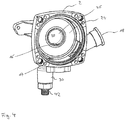
- Fig. 1 and 2 show the exemplary overall structure of a pump unit according to the invention.
- the pump unit has a pump housing 2, which with a stator or motor housing 4 is connected, in which a not shown here in detail electric drive motor is arranged.
- an electronics housing 6 is attached, in which the electrical connections of the drive motor and electronic components for controlling or regulating the drive motor can be arranged.
- a gap pot or gap tube 8 is arranged, which separates a rotor space 10 from a stator space 12 in the interior of the motor housing 4.
- the stator is arranged in a known manner with the electrical windings, while in the rotor chamber 10, the rotor of the electric motor is rotatably mounted.
- the electric motor is thus designed as a wet-running electric motor, in which the rotor chamber 10 is filled with the liquid to be pumped by the pump unit, for example water.
- the pump unit for example water.
- an impeller 14 is arranged, which is rotatably connected to a rotor, which is arranged in the rotor chamber 10, so that the impeller 14 can be driven in rotation by the electric motor.
- the pump housing 2 has a suction connection 16 or suction connection 16 and a pressure connection or discharge connection 18.
- the suction connection 16 opens in the interior of the pump housing into a suction chamber 20, which is separated from the pressure chamber 22 surrounding the impeller 14 by a deflector plate 24.
- the deflector plate 24 thus forms a partition wall between the pressure chamber 22 and the suction chamber 20.
- the deflector plate 24 has a central opening 26, which faces the suction mouth 28 of the impeller 14 or with its peripheral collar with the suction port 28 of the impeller 14 is engaged .
- the impeller 14 rotates and sucks in the region of its suction mouth 28 through the opening 26 liquid from the suction chamber 20 at.
- the liquid then exits the impeller 14 in the pressure chamber 22 on the outer circumference.
- the pressure chamber 22 is with connected to the pressure port 18 through which the pumped liquid exits the pump unit.
- the pump unit according to the invention has on its underside an emptying port 30, which opens into the suction chamber 20 in the interior of the pump housing and branches off from it.
- the emptying port 30 has two functions in the pump according to the invention. On the one hand, it enables the pump housing 2 to be emptied of liquid in its interior. On the other hand, it also allows the ventilation of the suction chamber 20, as will be described below.
- Fig. 3 shows a plan view into the interior of the open pump housing 2 without the deflector plate 24.
- the pump housing 2 is formed in this example as a one-piece cast component, in particular made of plastic. From the pump housing 2 branches off at the outer periphery of the pressure port 18 from. The suction port 16 extends from the axial end face 32 of the pump housing 2 to the outside. From the bottom of the emptying port 30 branches off.
- the directions mentioned relate to the axis of rotation X, which extends in the intended operating position of the pump unit in the horizontal direction. That is, the Fig. 1 and 3 show the position of the pump unit or the pump housing 2, as provided for the operation.
- the arrangement of the pressure port 18 on the side and the arrangement of the discharge port 30 on the underside of the pump housing 2 have the advantage that the top of the pump housing 2 remains free, so that overall the height of the pump housing is reduced, which is advantageous for certain applications.
- the pressure connection 18 could, for example, also be arranged on the upper side of the pump housing 2.
- the emptying connection 30 opens inside the pump housing 2 into a channel 34.
- the emptying connection 30 extends with a tubular section 36 parallel to the diameter axis Y to a certain extent into the interior of the pump housing 2.
- At its inner or upper end of the tubular portion 36 opens into the channel 34.
- the channel 34 is formed by two mutually parallel ribs 38.
- the ribs 38 are formed integrally with the pump housing 2 and extend away from the rear end wall 32.
- the ribs 36 define the channel 34 and thus form a groove, which is open to the side facing away from the end face 32 side. This page is, as will be described below, closed by the deflector plate 34 used.
- the channel 34 terminates at an opening 40 near the top of the suction chamber 20, that is, just before the upper peripheral wall, which limits the suction chamber 20 circumferentially with respect to the axis of rotation X.
- the channel 34 extends from the upper end of the tubular portion 36 initially arcuately about the axis of rotation X and then in its last, adjacent to the opening 40 portion in the direction of the diameter axis Y.
- the arcuate course serves to ensure that the channel 34 to the central opening 26 in the deflector plate 24 can run around arcuately.
- the deflector plate 24 is located on the free end edges of the ribs 38, that is, on the axial end face 32 of the pump housing 2 side facing away, so that the channel 34 is bounded on this side by the deflector plate 24 and only to its upper end the opening 40 in the suction chamber 20 is open.
- a valve element 42 is inserted from below.
- the valve element 42 is hollow and has in its interior a in the direction of the longitudinal axis L extending drain channel 44.
- the valve element 42 provided with a slotted guide, which is formed by two substantially helically extending grooves 50 on the outer circumference of the valve element 42. In these grooves 50 engage radially inwardly directed projections 52 on the inner circumference of the emptying port 30 a.
- This slotted guide causes that upon rotation of the valve element 42 about its longitudinal axis L at the same time a defined axial movement along the longitudinal axis L is caused.
- this has at its from the discharge port 30 outwardly projecting portion a hexagon 54. This can be designed so that it can be grasped with a conventional wrench.
- the valve member 42 is stepped so that it tapers in three stages from the end with the hex 54 to the end with the opening 48.
- the inner contour of the emptying connection 30 is designed to correspond, so that the cross-sectional shape essentially corresponds to the outer cross section of the valve element 42.
- the valve element 42 has on its outer circumference three spaced apart in the axial direction L seals in the form of O-rings 56, 58 and 60 on.
- the O-ring 56 located furthest down, that is to say towards the threaded connection 46, seals the outer circumference of the valve element 42 with respect to the inner wall of the emptying connection 30 in such a way that it sealingly seals on the inner circumference of the emptying connection 30 in all three operating positions of the valve element 44 described below is applied.
- the upper O-rings 56 and 58 which are smaller in diameter and located in the tapered portions of the valve member 42, form sealing seats or valve seals which serve to selectively open two possible flow paths or connections.
- Fig. 5 shows the rest position of the valve element 42, in which the valve element 42 inserted furthest into the discharge port 30 is. In this position, all three O-rings 56, 58, 60 sealingly abut the inner wall of the emptying port 30 and its tubular section 36, respectively.
- the opening 48 of the drainage channel 44 to the outer periphery of the valve element 42 is located in the axial direction L between the two upper O-rings 58 and 60.
- the uppermost O-ring 60 seals the channel 34 to the opening 48 down. That is, there is no connection between the discharge channel 44 and the channel 34, which establishes a connection to the upper region of the suction chamber 20.
- the valve element 42 When the valve element 42 is in the in Fig. 6 When the first switching position shown is turned, the valve element 42 simultaneously moves out of the emptying port 30 by a certain amount in the direction of the longitudinal axis L via the grooves 50 and the two projections 52. In this first switching position, the lower two O-rings 56 and 58 continue sealingly against the inner circumference of the emptying port 30. However, the upper O-ring 60 is disengaged from the inner wall of the exhaust port 30 and its tubular portion 36, respectively, so that a flow path or connection from the opening 48 in the valve element 42 to the opening 62, which the inlet opening in the channel 34 is open. In this first switching position, the emptying connection 30 thus has a first opened connection to a vertically upper region of the suction space 20.
- the valve element 42 In the second switching position, the valve element 42 is rotated a bit further, wherein the angle of rotation between the rest position and the first shift position and between the first shift position and the second shift position is preferably substantially 90 degrees.
- the valve element 42 has been moved out of the emptying connection 30 in the direction of the longitudinal axis L a further distance.
- the second, ie mean, O-ring 58 has now also come out of contact with the inner wall of the emptying connection 30.
- a further opening or connection 64 to the bottom region of the suction chamber 20 and the bottom region of the pressure chamber 22 is released. This connection 64 is in the sectional view in FIG Fig.
- connection 64 in the rest position according to Fig. 5 via the O-rings 56 and 58, the connection between the suction chamber 20 and the pressure chamber 22 is prevented via the connection 64.
- the pump housing 2 was shown as a separate component. However, it is to be understood that the pump housing 2 may also be part of an integrated hydraulic unit and so may be directly connected to other hydraulic components or formed integrally with these.
Abstract
Die Erfindung betrifft ein Pumpenaggregat mit einem Pumpengehäuse (2) und einem in diesem ausgebildeten Saugraum (20), welcher zumindest einen Entleerungsanschluss (30) aufweist, wobei der Entleerungsanschluss (30) eine erste Verbindung (34) zu einem vertikal oberhalb eines Bodenbereiches des Saugraumes gelegenen Bereich und eine zweite Verbindung (64) zu diesem Bodenbereich des Saugraumes (20) aufweist, und der Entleerungsanschluss (30) eine Ventileinrichtung (42) aufweist, welche es ermöglicht, in einer ersten Schaltstellung die erste Verbindung (34) und in einer zweiten Schaltstellung zumindest die zweite Verbindung (64) zu öffnen.


Description
Die Erfindung betrifft ein Pumpenaggregat mit einem Pumpengehäuse, in welchem ein Saugraum ausgebildet ist, welcher einen Entleerungsanschluss aufweist.The invention relates to a pump unit with a pump housing, in which a suction chamber is formed, which has an emptying port.
Pumpenaggregate, insbesondere Umwälzpumpenaggregate, wie sie in Heizungs- und Klimaanlagen zur Förderung von Brauchwasser und/oder flüssigen Wärmeträgern, insbesondere Wasser, eingesetzt werden, weisen im Inneren des Pumpengehäuses in ihrem Eingangsbereich, d. h. im Saugbereich, in der Regel einen Saugraum auf. Es ist bekannt, im Bereich dieses Saugraumes Einrichtungen zur Entlüftung anzuordnen. So sind automatische Entlüfter bekannt, welche an der Oberseite eines solchen Saugraumes angeordnet werden können. Diese automatischen Entlüfter können jedoch nicht unter allen Bedingungen eingesetzt werden. Darüber hinaus gibt es Anwendungen, in welchen es erforderlich ist, die Flüssigkeit aus der Anlage bzw. dem Pumpenaggregat abzulassen, beispielsweise zur Winterzeit, um ein Einfrieren zu verhindern.Pump units, in particular circulating pump units, as used in heating and air conditioning systems for the promotion of process water and / or liquid heat transfer, especially water, have inside the pump housing in its entrance area, d. H. in the suction area, usually a suction chamber. It is known to arrange facilities for venting in the region of this suction chamber. Thus, automatic deaerators are known which can be arranged on the upper side of such a suction space. However, these automatic breathers can not be used in all conditions. In addition, there are applications in which it is necessary to drain the fluid from the plant or the pump set, for example, in winter to prevent freezing.
Es ist Aufgabe der Erfindung, ein Pumpenaggregat mit einem Pumpengehäuse dahingehend zu verbessern, dass auf einfache Weise sowohl eine Entlüftung als auch eine Entleerung möglich ist. Diese Aufgabe wird durch ein Pumpenaggregat mit den in Anspruch 1 angegebenen Merkmalen gelöst. Bevorzugte Ausführungsformen ergeben sich aus den Unteransprüchen, der nachfolgenden Beschreibung sowie den beigefügten Figuren.It is an object of the invention to improve a pump unit with a pump housing to the effect that both a vent and a drain is possible in a simple manner. This object is achieved by a pump unit having the features specified in claim 1. Preferred embodiments will become apparent from the subclaims, the following description and the accompanying figures.
Das erfindungsgemäße Pumpenaggregat weist ein Pumpengehäuse auf, welches die Strömungswege durch das Pumpenaggregat für eine zu fördernde Flüssigkeit, insbesondere einem zu fördernden Wärmeträger, definiert. Diese Flüssigkeit kann insbesondere Wasser sein. Das Pumpengehäuse definiert einen Saugraum, welcher an der Eingangsseite des Pumpenaggregates gelegen ist und in welchen die zu fördernde Flüssigkeit eintritt. Dieser Saugraum weist zumindest einen Entleerungsanschluss auf, über welchen die Flüssigkeit aus dem Saugraum und vorzugsweise dem gesamten Pumpenaggregat abgelassen und das Pumpenaggregat bzw. der Saugraum entleert werden können. Erfindungsgemäß ist der Entleerungsanschluss mit zumindest zwei voneinander beabstandeten Bereichen im Inneren des Saugraumes verbunden. So weist der Entleerungsanschluss eine erste Verbindung zu einem zu entlüftenden Bereich des Saugraumes auf, welcher vertikal oberhalb eines Bodenbereiches des Saugraumes gelegen ist. Der zu entlüftende Bereich ist derjenige Bereich im Inneren des Saugraumes, in welchem sich zu entfernende Luft ansammelt. Ferner weist der Entleerungsanschluss eine zweite Verbindung auf, welche von dem Entleerungsanschluss zu dem Bodenbereich des Saugraumes führt bzw. den Entleerungsanschluss mit dem Bodenbereich des Saugraumes oder des gesamten Pumpengehäuses verbindet. Über die zweite Verbindung kann der Saugraum im Wesentlichen vollständig entleert werden, da diese im Bodenbereich mündet und dieser bei der zum Betrieb des Pumpenaggregates vorgesehenen Einbaulage im Wesentlichen den tiefsten Punkt des Saugraumes definiert, so dass von dort im Wesentlichen die gesamte Flüssigkeit aus dem Saugraum über den Entleerungsanschluss ablaufen kann. Die erste Verbindung zu einem vertikal höher gelegenen Bereich kann genutzt werden, um den Saugraum zu entlüften. Die vertikal höher gelegene Position bezieht sich dabei ebenfalls auf die vorgesehene Einbaulage des Pumpenaggregates beim Betrieb. Luft wird sich im Inneren des Saugraumes im oberen Bereich des Saugraumes ansammeln. Wenn der Entleerungsanschluss über die erste Verbindung mit einem derartigen oberen Bereich des Saugraumes verbunden ist, wird beim Öffnen des Entleerungsanschlusses durch den im Inneren des Saugraumes herrschenden Druckes Flüssigkeit durch die erste Verbindung in den Entleerungsanschluss gedrückt. Dabei nimmt die Flüssigkeit Luftansammlungen mit und zieht bzw. drückt diese über die erste Verbindung in den Entleerungsanschluss. Auf diese Weise ist eine Entlüftung über den Entleerungsanschluss möglich. Die zweite Verbindung ist besonders bevorzugt sowohl mit dem Bodenbereich des Saugraumes als auch mit dem Bodenbereich eines von dem Saugraum getrennten Druckraumes des Pumpengehäuses verbunden, sodass das Innere des gesamten Pumpengehäuses über diese Verbindung entleert werden kann.The pump unit according to the invention has a pump housing, which defines the flow paths through the pump unit for a liquid to be conveyed, in particular a heat transfer medium to be conveyed. This liquid may in particular be water. The pump housing defines a suction chamber, which is located on the input side of the pump unit and in which enters the liquid to be delivered. This suction chamber has at least one emptying connection, via which the fluid can be discharged from the suction space and preferably the entire pump unit and the pump unit or the suction space can be emptied. According to the emptying connection is connected to at least two spaced-apart areas in the interior of the suction chamber. Thus, the emptying connection has a first connection to a region of the suction chamber to be vented, which is located vertically above a bottom region of the suction chamber. The area to be deaerated is that area in the interior of the suction space in which air to be removed accumulates. Furthermore, the emptying connection has a second connection, which leads from the emptying connection to the bottom region of the suction chamber or connects the emptying connection to the bottom region of the suction chamber or the entire pump housing. About the second connection, the suction chamber can be substantially completely emptied, as this opens in the bottom area and this essentially defines the lowest point of the suction chamber at the intended installation position for operation of the pump unit, so that from there substantially all of the liquid from the suction chamber over can drain the emptying connection. The first connection to a higher vertical area can be used to vent the suction chamber. The vertically higher position also refers to the intended installation position of the pump unit during operation. Air will accumulate inside the suction chamber in the upper area of the suction chamber. When the drain port is over the first Connection is connected to such an upper region of the suction chamber, is pressed by the pressure prevailing in the interior of the suction chamber liquid through the first connection in the discharge port when opening the drain port. In doing so, the liquid absorbs air accumulations and pulls or presses them via the first connection into the emptying connection. In this way, venting via the drain connection is possible. The second connection is particularly preferably connected both to the bottom region of the suction chamber and to the bottom region of a pressure chamber of the pump housing which is separate from the suction chamber, so that the interior of the entire pump housing can be emptied via this connection.
Erfindungsgemäß ist an dem oder in dem Entleerungsanschluss eine Ventileinrichtung angeordnet, welche so ausgebildet ist, dass sie zumindest zwei unterschiedliche Schaltstellungen aufweist, wobei in einer ersten Schaltstellung die erste Verbindung und in einer zweiten Schaltstellung zumindest die zweite Verbindung geöffnet ist. Alternativ können in der zweiten Schaltstellung auch beide Verbindungen geöffnet sein. Die erste Schaltstellung dient somit der Entlüftung. In dieser Schaltstellung ist nur die Verbindung zu dem vertikal oberen Bereich im Inneren des Saugraumes geöffnet, so dass dieser Bereich in der vorangehend beschriebenen Weise entlüftet werden kann. In der zweiten Schaltstellung ist die Verbindung zu dem Bodenbereich des Saugraumes bzw. des Saug- und Druckraumes hin geöffnet, so dass im Wesentlichen die gesamte Flüssigkeit aus dem Saugraum bzw. dem Pumpengehäuse durch den Entleerungsanschluss ablaufen kann. Weiter bevorzugt weist die Ventileinrichtung auch noch eine Ruhestellung auf, in welcher beide Verbindungen geschlossen sind. Dies ist die Position, welche die Ventileinrichtung beim normalen Betrieb des Pumpenaggregates hat. Die erfindungsgemäße Lösung ermöglicht es, über ein und denselben Anschluss, nämlich den erfindungsgemäßen Entleerungsanschluss, das Pumpengehäuse sowohl zu entlüften als auch vollständig zu entleeren.According to the invention, a valve device is arranged on or in the emptying connection which is designed such that it has at least two different switching positions, wherein in a first switching position the first connection and in a second switching position at least the second connection is opened. Alternatively, both connections can be opened in the second switching position. The first switching position thus serves for venting. In this switching position, only the connection to the vertical upper region in the interior of the suction chamber is opened, so that this region can be vented in the manner described above. In the second switching position, the connection to the bottom region of the suction chamber or of the suction and pressure chamber is opened so that substantially all the liquid from the suction chamber or the pump housing can drain through the emptying connection. More preferably, the valve device also has a rest position in which both connections are closed. This is the position that the valve device has during normal operation of the pump set. The solution according to the invention makes it possible, via one and the same connection, namely the emptying connection according to the invention, Both to vent the pump housing and to empty completely.
Die erste Verbindung mündet vorzugsweise in einen Bereich des vertikal oberen Endes des Saugraumes und weiter bevorzugt in einem oberen Viertel des Saugraumes. Der vertikale Abstand der Mündung der ersten Verbindung vom oberen Ende des Saugraumes ist vorzugsweise kleiner als 25 %, weiter bevorzugt kleiner als 10 % und noch weiter bevorzugt kleiner als 5 % der Gesamthöhe des Saugraumes in vertikaler Richtung. Die vertikale Richtung des Saugraumes ist dabei diejenige Achse des Saugraumes, welche sich bei der vorgesehenen Betriebslage des Pumpenaggregates in vertikaler Richtung erstreckt.The first connection preferably opens into a region of the vertically upper end of the suction chamber and more preferably in an upper fourth of the suction chamber. The vertical distance of the mouth of the first connection from the upper end of the suction chamber is preferably less than 25%, more preferably less than 10% and even more preferably less than 5% of the total height of the suction chamber in the vertical direction. The vertical direction of the suction chamber is that axis of the suction chamber, which extends in the intended operating position of the pump unit in the vertical direction.
Weiter bevorzugt ist das Pumpenaggregat als Kreiselpumpenaggregat mit zumindest einem drehend angetriebenen Laufrad ausgebildet. Bei einem derartigen Kreiselpumpenaggregat liegt in der vorgesehenen Betriebslage die Drehachse des Laufrades vorzugsweise in horizontaler Richtung, so dass die vertikale Erstreckung des Saugraumes, wie sie oben beschrieben wurde, sich normal zu der Drehachse erstreckt. Das Kreiselpumpenaggregat kann weiter bevorzugt als nasslaufendes Kreiselpumpenaggregat ausgebildet sein, d. h., mit einem nasslaufenden elektrischen Antriebsmotor, bei welchem Stator und Rotor durch einen Spalttopf bzw. ein Spaltrohr voneinander getrennt sind. Vorzugsweise mündet in dem Kreiselpumpenaggregat die erste Verbindung oberhalb eines Saugmundes des Laufrades in den Saugraum. Dadurch wird sichergestellt, dass Luft aus dem Saugraum abgeführt werden kann, bevor sie in den Saugmund eintritt und die Förderung durch das Laufrad blockieren würde.More preferably, the pump unit is designed as a centrifugal pump unit with at least one rotationally driven impeller. In such a centrifugal pump assembly is in the intended operating position, the axis of rotation of the impeller preferably in the horizontal direction, so that the vertical extent of the suction chamber, as described above, extends normal to the axis of rotation. The centrifugal pump unit may be further preferably designed as a wet-running centrifugal pump unit, d. h., With a wet-running electric drive motor, wherein the stator and rotor are separated by a split pot or a can. Preferably, in the centrifugal pump assembly, the first connection opens above a suction mouth of the impeller in the suction chamber. This ensures that air can be removed from the suction chamber before it enters the suction port and would block the delivery through the impeller.
Weiter bevorzugt kann das Pumpenaggregat Teil einer hydraulischen Baueinheit bzw. eines hydraulischen Blocks sein, wie er beispielsweise in Kompaktheizungsanlagen Verwendung findet. Eine solche hydraulische Baueinheit integriert alle wesentlichen hydraulischen Komponenten bzw. Strömungswege einer derartigen Heizungsanlage und kann beispielsweise zusätzlich ein oder mehrere Ventile, einen Wärmetauscher zur Erwärmung von Brauchwasser, erforderliche Sensoren und Anschlüsse für die Frischwasserzu- und -abfuhr sowie externe Heizkreise aufweisen. Ferner weist eine solche Baueinheit vorzugsweise Anschlüsse für eine Wärmequelle wie einen Primärwärmetauscher eines Heizkessels auf.More preferably, the pump unit may be part of a hydraulic unit or a hydraulic block, as used for example in compact heating systems. Such a hydraulic Assembly unit integrates all the essential hydraulic components or flow paths of such a heating system and, for example, additionally have one or more valves, a heat exchanger for heating process water, required sensors and connections for fresh water supply and removal and external heating circuits. Furthermore, such a unit preferably has connections for a heat source such as a primary heat exchanger of a boiler.
Das Pumpenaggregat weist an seinem Pumpengehäuse vorzugsweise einen saugseitigen Anschluss auf, welcher in den Saugraum mündet. Dieser kann sich in der vorgesehen Einbaulage beispielsweise nach unten oder aber auch, ausgehend von der axialen Stirnseite des Pumpengehäuses, d. h., im Wesentlichen in horizontaler Richtung, in der bevorzugten Einbaulage erstrecken. Ferner weist das Pumpengehäuse vorzugsweise einen Druckraum auf, welcher im Falle eines Kreiselpumpenaggregates das zumindest eine Laufrad umgibt und welcher mit einem Druckanschluss, d. h., einem ausgangsseitigen Anschluss des Pumpengehäuses versehen ist. Der Druckanschluss kann sich dabei in der vorgesehenen Einbaulage beispielsweise nach oben oder auch seitlich von dem Pumpengehäuse weg erstrecken.The pump unit preferably has on its pump housing a suction-side connection, which opens into the suction chamber. This can be in the intended installation position, for example, down or even, starting from the axial end face of the pump housing, d. h., Essentially in the horizontal direction, in the preferred mounting position. Furthermore, the pump housing preferably has a pressure chamber which, in the case of a centrifugal pump assembly, surrounds the at least one impeller and which has a pressure connection, ie. h., An output-side connection of the pump housing is provided. The pressure port may extend in the intended mounting position, for example, upwards or laterally away from the pump housing.
Die erste Verbindung wird vorzugsweise durch einen Kanal gebildet, welcher zwischen einer Wandung des Pumpengehäuses, insbesondere einer stirnseitigen Wandung und einer in das Pumpengehäuse eingesetzten Deflektorplatte ausgebildet ist, wobei die Deflektorplatte den Saugmund des Laufrades umgibt. Die Deflektorplatte trennt dabei den Saugraum von dem Druckraum im Inneren des Pumpengehäuses. Die Deflektorplatte weist eine zentrale Öffnung auf, welche mit dem Saugmund des Laufrades in Eingriff ist und durch welche die von dem Laufrad angesaugte Flüssigkeit in den Saugmund eintritt. Aus fertigungstechnischen Gründen ist eine derartige Deflektorplatte häufig als separates Bauteil ausgebildet, welches in das Pumpengehäuse eingesetzt ist. Dies ist insbesondere der Fall, wenn das Pumpengehäuse, wie bevorzugt, als Gussbauteil aus Kunststoff oder Metall gefertigt ist. In einem solchen Fall vermeidet die Deflektorplatte die Ausbildung von nicht oder nur schwer zu entkernenden Hinterschneidungen im Inneren des Pumpengehäuses.The first connection is preferably formed by a channel which is formed between a wall of the pump housing, in particular an end wall and a deflector plate inserted into the pump housing, wherein the deflector plate surrounds the suction mouth of the impeller. The deflector plate separates the suction chamber from the pressure chamber in the interior of the pump housing. The deflector plate has a central opening which engages the suction mouth of the impeller and through which the liquid sucked by the impeller enters the suction mouth. For manufacturing reasons, such a deflector plate is often as a separate Part formed, which is inserted into the pump housing. This is the case in particular if the pump housing, as preferred, is manufactured as a cast component from plastic or metal. In such a case, the deflector plate avoids the formation of undercuts that are difficult or impossible to remove inside the pump housing.
Die Ausbildung der Verbindung bzw. des Kanals zwischen der Deflektorplatte und einer Wandung des Pumpengehäuses hat den Vorteil, dass die Verbindung als Kanal sehr einfach ausgebildet werden kann, da der Kanal im Wesentlichen beim Gießen des Pumpengehäuses, wenn dieses als Gussbauteil ausgebildet wird, mitgeformt werden kann und dann an einer verbleibenden offenen Seite durch die Deflektorplatte verschlossen werden kann. D. h., der Kanal kann beim Gießen als offene Rinne ausgebildet werden, welche leicht zu entkernen ist.The formation of the connection or the channel between the deflector plate and a wall of the pump housing has the advantage that the connection can be made very simple as a channel, since the channel substantially in the casting of the pump housing, if this is formed as a cast component mitgeformt can and can then be closed on a remaining open side by the deflector plate. D. h., The channel can be formed during casting as an open channel, which is easy to core.
So ist der Kanal vorzugsweise durch zwei von einer axialen Stirnwandung des Pumpengehäuses vorstehende Rippen begrenzt. Die Rippen verlaufen dabei weiter bevorzugt im Wesentlichen parallel zueinander und bilden Seitenwandungen des Kanals. Die Deflektorplatte kommt an den der Stirnwandung des Pumpengehäuses abgewandten Kanten der Rippe zumindest teilweise zur Anlage. Vorzugsweise liegt die Deflektorplatte im Wesentlichen über die gesamte Länge an den Kanten der Rippen an, so dass die offene Seite des Kanals durch die Deflektorplatte verschlossen wird. Dabei ist zu verstehen, dass die Anlage der Deflektorplatte an den Rippen nicht vollständig dicht zu sein braucht. Vorzugsweise sollten jedoch verbleibende Spalte zwischen Deflektorplatte und den Rippen kleiner sein als die Öffnung des Kanals an seinem Ende, welche die vorgesehene Eintrittsöffnung in den Kanal bildet.Thus, the channel is preferably delimited by two ribs projecting from an axial end wall of the pump housing. The ribs furthermore preferably run essentially parallel to one another and form side walls of the channel. The deflector plate comes at least partially against the end wall of the pump housing facing edges of the rib to rest. Preferably, the deflector plate abuts substantially the entire length at the edges of the ribs so that the open side of the channel is closed by the deflector plate. It should be understood that the installation of the deflector plate on the ribs need not be completely sealed. Preferably, however, remaining gaps between the deflector plate and the ribs should be smaller than the opening of the channel at its end, which forms the intended inlet opening in the channel.
Besonders bevorzugt sind die Rippen einstückig mit der Stirnwandung des Pumpengehäuses, vorzugsweise aus Metall oder Kunststoff, ausgebildet. Die Stirnwandung des Pumpengehäuses ist die axiale Endwandung, welche sich im Falle eines Kreiselpumpenaggregates im Wesentlichen quer zur Drehachse des Laufrades erstreckt. Dabei ist die Wandung diejenige Wandung, welche an dem dem Laufrad entgegengesetzten Axialende des Pumpengehäuses ausgebildet ist. An dem dem Laufrad zugewandten Axialende ist das Pumpengehäuse bevorzugt offen ausgebildet und wird durch einen angesetzten Antriebsmotor bzw. dessen Spaltrohr verschlossen, wenn es sich bei dem Antriebsmotor, wie bevorzugt, um einen nasslaufenden elektrischen Antriebsmotor handelt.Particularly preferably, the ribs are integral with the end wall of the pump housing, preferably made of metal or plastic, educated. The end wall of the pump housing is the axial end wall, which extends in the case of a centrifugal pump assembly substantially transverse to the axis of rotation of the impeller. In this case, the wall is that wall which is formed on the impeller opposite axial end of the pump housing. At the axial end facing the impeller, the pump housing is preferably designed to be open and is closed by an attached drive motor or its can, when the drive motor, as preferred, is a wet-running electric drive motor.
Weiter bevorzugt verläuft der Kanal zumindest in einem an sein oberes Ende angrenzenden Abschnitt vertikal und vorzugsweise in Richtung eines Durchmessers des Pumpengehäuses quer zu der Drehachse des Laufrades. Wenn der Kanal, wie vorangehend beschrieben, zwischen der Stirnwandung des Pumpengehäuses und der Deflektorplatte ausgebildet ist, verläuft der Kanal in einem vertikal unteren Bereich bevorzugt bogenförmig im Umfangsbereich der zentralen Öffnung in der Deflektorplatte, welche mit dem Saugmund des Laufrades in Eingriff ist.More preferably, the channel extends at least in a direction adjacent to its upper end portion vertically and preferably in the direction of a diameter of the pump housing transverse to the axis of rotation of the impeller. When the passage is formed between the end wall of the pump housing and the deflector plate as described above, the passage in a vertically lower portion is preferably arcuate in the peripheral portion of the central opening in the deflector plate which is engaged with the suction port of the impeller.
Gemäß einer weiteren bevorzugten Ausführungsform erstreckt sich zumindest eine vertikal obere Seitenfläche des Kanals in allen Bereichen gewinkelt zur Horizontalen und vorzugsweise in vertikaler Richtung ansteigend zum oberen Ende des Kanals. Dadurch wird verhindert, dass der Kanal Toträume aufweist, in welchen sich Luftblasen ansammeln und halten können. Die vertikal obere Seitenfläche ist dabei bevorzugt eine Seitenfläche des Kanals, welche sich zwischen der Stirnseite des Pumpengehäuses und der Deflektorplatte erstreckt.According to a further preferred embodiment, at least one vertically upper side surface of the channel extends in all areas angled to the horizontal and preferably in the vertical direction rising to the upper end of the channel. This prevents the channel from having dead spaces in which air bubbles can accumulate and hold. The vertically upper side surface is preferably a side surface of the channel, which extends between the end face of the pump housing and the deflector plate.
Der Entleerungsanschluss ist weiter bevorzugt an einer Unterseite des Pumpengehäuses gelegen und zur Unterseite hin geöffnet ausgebildet. Dies begünstigt den Ablauf der Flüssigkeit durch den Entleerungsanschluss. Darüber hinaus ist es bei vielen Pumpenaggregaten, insbesondere bei der Verwendung in einer hydraulischen Baueinheit, wie sie vorangehend beschrieben wurde, bevorzugt, dass alle wesentlichen Anschlüsse an der Unterseite angeordnet sind. So kann ein Zugangs- bzw. Anschlussbereich des Pumpenaggregates bzw. der hydraulischen Baueinheit an der Unterseite ausgebildet sein.The emptying port is further preferably located on an underside of the pump housing and open towards the bottom. This promotes the drainage of the liquid through the discharge port. Moreover, in many pump assemblies, particularly when used in a hydraulic assembly as described above, it is preferred that all of the essential connections be located at the bottom. Thus, an access or connection region of the pump assembly or the hydraulic assembly may be formed on the underside.
Gemäß einer weiteren bevorzugten Ausführungsform weist die Ventileinrichtung ein zwischen den Schaltstellungen drehbares und/oder linear bewegbares Ventilelement auf. D. h., um die Verbindungen des Entleerungsanschlusses, wie sie vorangehend beschrieben wurden, gezielt zu öffnen, kann das Ventilelement zwischen der ersten und der zweiten Schaltstellung drehend und/oder linear bewegt werden. Zusätzlich ist bevorzugt eine Bewegung zwischen einer Ruhestellung, in welcher der Entleerungsanschluss vollständig geschlossen ist und den Schaltstellungen möglich.According to a further preferred embodiment, the valve device has a valve element rotatable between the switching positions and / or linearly movable. In other words, in order to selectively open the connections of the emptying connection, as described above, the valve element can be moved rotationally and / or linearly between the first and the second switching position. In addition, a movement between a rest position in which the emptying connection is completely closed and the switching positions is possible is preferred.
Das Ventilelement ist bevorzugt in den Entleerungsanschluss eingesetzt, insbesondere von unten her eingesetzt. Weiter bevorzugt ist das Ventilelement von der Unterseite des Pumpenaggregates her bedienbar. Dies hat den Vorteil, dass das Ventilelement von der Seite her bedienbar ist, zu der auch der Ablauf des Entleerungsanschlusses gelegen ist. Insbesondere, wenn es einen zentralen Anschlussbereich des Pumpenaggregates oder einer hydraulischen Baueinheit, in welche das Pumpenaggregat integriert ist, an der Unterseite gibt, ist es zweckmäßig, von dort auch das Ventilelement zu bedienen.The valve element is preferably inserted into the emptying connection, in particular inserted from below. More preferably, the valve element is operable from the bottom of the pump unit. This has the advantage that the valve element can be operated from the side to which the outlet of the discharge port is located. In particular, if there is a central connection region of the pump unit or a hydraulic unit, in which the pump unit is integrated, at the bottom, it is expedient to operate from there, the valve element.
Besonders bevorzugt ist das Ventilelement mit dem Entleerungsanschluss über eine Kulissenführung in Eingriff, welche derart ausgebildet ist, dass eine Drehung des Ventilelementes zu einer gleichzeitigen axialen Verlagerung des Ventilelementes in dem Entleerungsanschluss führt. Dazu kann beispielsweise am Außenumfang des Ventilelements, welches in den Entleerungsanschluss eingesetzt ist, zumindest eine im Wesentlichen schraubenförmig verlaufende Nut ausgebildet sein, in welche zumindest ein Stift am Innenumfang des Entleerungsanschlusses eingreift. Wird nun das Ventilelement gedreht, gleitet der Stift in der Nut und bewirkt gleichzeitig eine Axialbewegung des Ventilelementes. Das Ventilelement weist bevorzugt Dichtflächen bzw. Dichtsitze auf, welche in axialer Richtung in und außer Eingriff gebracht werden. D. h., über die Kulissenführung kann dann durch Drehung des Ventilelementes eine axiale Verlagerung bewirkt werden, welche die Dichtflächen bzw. Dichtsitze in und außer Eingriff bringt, um die Verbindungen zu dem Entleerungsanschluss öffnen und schließen zu können. Die Drehung des Ventilelementes ermöglicht eine leichte Bedienbarkeit. Die Axialbewegung begünstigt das in und außer Eingriff bringen der Dichtflächen bzw. Dichtsitze.Particularly preferably, the valve element is in engagement with the emptying connection via a slotted guide, which is embodied such that rotation of the valve element results in a simultaneous axial displacement of the valve element in the emptying connection. For this purpose, for example, on the outer circumference of the valve element, which is inserted into the emptying connection, at least one essentially helically extending groove can be formed, into which at least one pin engages on the inner circumference of the emptying connection. If now the valve element is rotated, the pin slides in the groove and simultaneously causes an axial movement of the valve element. The valve element preferably has sealing surfaces or sealing seats, which are brought into and out of engagement in the axial direction. D. h., Via the slotted guide can then be effected by rotation of the valve element, an axial displacement, which brings the sealing surfaces or sealing seats in and out of engagement to open and close the connections to the discharge port. The rotation of the valve element allows easy operation. The axial movement favors the engagement and disengagement of the sealing surfaces or sealing seats.
Bevorzugt verschließt das Ventilelement in einer Ruhelage in dem Entleerungsanschluss sowohl die erste Verbindung als auch die zweite Verbindung. In einer ersten, von der Ruhelage abweichenden Schaltstellung gibt das Ventilelement vorzugsweise eine Öffnung zu der ersten Verbindung frei. In dieser Schaltstellung ist somit eine Verbindung zum vertikal oberen Bereich des Saugraumes gegeben, so dass eine Entlüftung erfolgen kann. In einer zweiten, von der Ruhelage und der ersten Schaltstellung abweichenden Schaltstellung gibt das Ventilelement vorzugsweise eine Öffnung zu der zweiten Verbindung frei, welche im Bodenbereich des Saugraumes endet, um den Saugraum zu entleeren. In dieser zweiten Schaltstellung kann gegebenenfalls gleichzeitig auch die erste Verbindung zu dem oberen Bereich des Saugraumes geöffnet sein.Preferably, the valve element closes both the first connection and the second connection in a rest position in the emptying connection. In a first switching position deviating from the rest position, the valve element preferably releases an opening to the first connection. In this switching position thus a connection to the vertical upper portion of the suction chamber is given, so that a vent can be done. In a second switching position deviating from the rest position and the first switching position, the valve element preferably releases an opening to the second connection, which ends in the bottom region of the suction chamber in order to empty the suction chamber. If appropriate, the first connection to the upper region of the suction chamber may also be opened at the same time in this second switching position.
Das Ventilelement kann gemäß einer weiteren bevorzugten Ausführungsform eine erste Dichtfläche aufweisen, welche in der Ruhelage dichtend an einem Ventilsitz bzw. einer Wandung in der Entleerungsöffnung anliegt und in der ersten und der zweiten Schaltstellung von dem Ventilsitz bzw. der Wandung beabstandet ist. So wird in der ersten und der zweiten Schaltstellung die Öffnung an diesem Ventilsitz geöffnet, wobei es sich dabei um eine Öffnung zu der ersten Verbindung hin handelt. Ferner weist das Ventilelement vorzugsweise eine zweite Dichtfläche auf, welche in der Ruhelage und der ersten Schaltstellung dichtend an einer Wandung der Entleerungsöffnung anliegt und in der zweiten Schaltstellung von dieser Wandung der Entleerungsöffnung beabstandet ist, wodurch ein Strömungsweg zu der zweiten Verbindung zum Bodenbereich des Saugraumes freigegeben wird, um diesen zu entleeren. Die erste und die zweite Dichtfläche sind vorzugsweise als ringförmige Dichtflächen bzw. Dichtringe ausgebildet. Solche Dichtringe können beispielsweise durch O-Ringe gebildet werden. Die Abdichtung erfolgt vorzugsweise radial gegen eine umfänglich umgebende Innenwandung der Entleerungsöffnung. Das Außereingrifftreten dieser ringförmigen Dichtsitze bzw. Dichtflächen von den Wandungen durch die Axialbewegung wird dadurch erreicht, dass sich die Entleerungsöffnung in ihrem Inneren stufenförmig erweitert bzw. stufenförmige Umfangserweiterungen aufweist. Zum Öffnen des jeweiligen Ventilsitzes wird die ringförmige Dichtfläche durch axiale Bewegung in den Bereich einer Umfangserweiterung bewegt, sodass ein Freiraum zwischen der Dichtfläche und der nun radial beabstandeten Umfangserweiterung geschaffen wird, durch welchen eine Strömung verlaufen kann. Die beschriebenen Umfangserweiterungen müssen nicht im gesamten Umfang erfolgen. Vielmehr kann dies jeweils auch nur in einem Umfangsabschnitt der Fall sein.According to a further preferred embodiment, the valve element can have a first sealing surface which, in the rest position, seals against a valve seat or a wall in the discharge opening is applied and spaced in the first and the second switching position of the valve seat or the wall. Thus, in the first and second switching positions, the opening on this valve seat is opened, which is an opening to the first connection. Furthermore, the valve element preferably has a second sealing surface, which rests in the rest position and the first switching position sealingly on a wall of the discharge opening and is spaced in the second switching position of this wall of the discharge opening, thereby releasing a flow path to the second connection to the bottom region of the suction chamber will be to empty this. The first and second sealing surfaces are preferably designed as annular sealing surfaces or sealing rings. Such sealing rings can be formed for example by O-rings. The seal is preferably carried out radially against a circumferentially surrounding inner wall of the discharge opening. The disengagement of these annular sealing seats or sealing surfaces of the walls by the axial movement is achieved in that the discharge opening in its interior extends stepwise or stepped circumferential extensions. To open the respective valve seat, the annular sealing surface is moved by axial movement in the region of a circumferential extension, so that a clearance between the sealing surface and the now radially spaced circumferential extension is provided, through which a flow can pass. The described extent extensions do not have to be made in their entirety. Rather, this can also be the case only in a peripheral section.
Gemäß einer weiteren bevorzugten Ausführungsform der Erfindung weist das Ventilelement in seinem Inneren einen Entleerungskanal auf, welcher in der ersten Schaltstellung mit der ersten Verbindung sowie in der zweiten Schaltstellung mit der zweiten Verbindung und vorzugsweise in der zweiten Schaltstellung sowohl mit der ersten als auch mit der zweiten Verbindung verbunden ist. An seinem von dem Pumpengehäuse beabstandeten Axialende kann der Entleerungskanal in einen Schlauch- bzw. Leitungsanschluss münden, an welchem eine Entwässerungsleitung bzw. ein Entwässerungsschlauch zum Abführen des austretenden Wassers bzw. der austretenden Flüssigkeit angeschlossen werden kann. Der Entleerungskanal mündet an dem entgegengesetzten Ende vorzugsweise in einen Umfangsbereich des Ventilelementes, bezogen auf die lineare Bewegungsachse des Ventilelementes. Die Öffnung in dem Umfangsbereich ist dabei vorzugsweise zwischen einer ersten und einer zweiten Dichtfläche, wie sie vorangehend beschrieben wurde, gelegen. So kann die erste Dichtfläche, wenn sie von dem zugehörigen Ventilsitz bzw. der umgebenden Wandung wegbewegt wird, einen ersten Strömungsweg zu der Öffnung in den Entleerungskanal freigeben, während die zweite Dichtfläche, wenn sie von ihrem zugehörigen Dichtsitz bzw. einer Wandung des Entleerungsanschlusses außer Anlage tritt, einen zweiten Strömungsweg von der zweiten Verbindung zu der Öffnung des Entleerungskanals freigeben.According to a further preferred embodiment of the invention, the valve element has in its interior an emptying channel, which in the first switching position with the first connection and in the second switching position with the second compound and preferably in the second switching position with both the first and connected to the second connection. At its axial end which is at a distance from the pump housing, the emptying channel can open into a hose or line connection to which a drainage line or a drainage hose for discharging the outflowing water or the exiting liquid can be connected. The emptying channel opens at the opposite end preferably in a peripheral region of the valve element, based on the linear axis of movement of the valve element. The opening in the peripheral region is preferably located between a first and a second sealing surface, as described above. Thus, the first sealing surface, when moved away from the associated valve seat or the surrounding wall, release a first flow path to the opening in the discharge channel, while the second sealing surface, when out of their associated sealing seat or a wall of the emptying port out of engagement occurs to release a second flow path from the second connection to the opening of the discharge channel.
Das Ventilelement ist vorzugsweise ebenfalls als Kunststoff-Spritzgussteil ausgebildet und die erforderlichen Dichtungen bzw. Dichtflächen sind durch O-Ringe gebildet, welche in Nuten am Außenumfang eingesetzt sind. Dabei sind vorzugsweise drei Dichtungen vorgesehen, zwei, welche die erste und die zweite Dichtfläche bilden, wie sie vorangehend beschrieben wurden und eine dritte Dichtung, welche eine dauerhafte Abdichtung in allen Schaltstellungen zwischen dem Ventilelement und einer Innenwandung des Entleerungsanschlusses herstellt, um sicherzustellen, dass Flüssigkeit nur durch den vorangehend beschriebenen Entleerungskanal nach außen austritt und nicht zwischen Ventilelement und Entleerungsanschluss nach außen austritt.The valve element is preferably also formed as a plastic injection-molded part and the required seals or sealing surfaces are formed by O-rings, which are inserted into grooves on the outer circumference. Preferably, there are provided three seals, two forming the first and second sealing surfaces as described above and a third seal providing a permanent seal in all switching positions between the valve member and an inner wall of the exhaust port to ensure that liquid only escapes to the outside through the drainage channel described above and does not escape to the outside between the valve element and the drainage connection.
Nachfolgend wird die Erfindung beispielhaft anhand der beigefügten Figuren beschrieben. In diesen zeigt:
- Fig. 1.
- eine Außenansicht eines erfindungsgemäßen Pumpenaggregates,
- Fig. 2
- eine Schnittansicht des erfindungsgemäßen Pumpenaggregates entlang der Linie C-C in
Fig. 1 , - Fig. 3
- eine Draufsicht auf das geöffnete Pumpengehäuse des Pumpenaggregates gemäß
Fig. 1 ,und 2 - Fig. 4
- eine perspektivische Ansicht des geöffneten Pumpengehäuses gemäß
Fig. 3 mit eingesetzter Deflektorplatte, - Fig. 5
- eine Schnittansicht des Pumpengehäuses entlang der Linien A-A in
Fig. 3 , jedoch mit eingesetzter Deflektorplatte und eingesetztem Ventilelement in seiner Ruhelage, - Fig. 6
- eine Schnittansicht entsprechend
Fig. 5 , in welcher sich das Ventilelement in einer ersten Schaltstellung befindet, - Fig. 7
- eine Schnittansicht gemäß
Fig. 5 und 6 , wobei sich das Ventilelement in einer zweiten Schaltstellung befindet, - Fig. 8
- eine perspektivische Außenansicht des Ventilelementes,
- Fig. 9
- eine Schnittansicht entlang der Linie D-D in
Fig. 5 , und - Fig. 10
- eine Schnittansicht entlang der Linie B-B in
Fig. 7 .
- Fig. 1.
- an external view of a pump unit according to the invention,
- Fig. 2
- a sectional view of the pump assembly according to the invention along the line CC in
Fig. 1 . - Fig. 3
- a plan view of the open pump housing of the pump unit according to
Fig. 1 and 2 . - Fig. 4
- a perspective view of the open pump housing according to
Fig. 3 with inserted deflector plate, - Fig. 5
- a sectional view of the pump housing along the lines AA in
Fig. 3 , but with inserted deflector plate and inserted valve element in its rest position, - Fig. 6
- a sectional view accordingly
Fig. 5 in which the valve element is in a first switching position, - Fig. 7
- a sectional view according to
Fig. 5 and6 , wherein the valve element is in a second switching position, - Fig. 8
- an external perspective view of the valve element,
- Fig. 9
- a sectional view taken along the line DD in
Fig. 5 , and - Fig. 10
- a sectional view taken along the line BB in
Fig. 7 ,
Das Pumpengehäuse 2 weist einen Sauganschluss 16 bzw. Saugstutzen 16 sowie einen Druckanschluss bzw. Druckstutzen 18 auf. Der Sauganschluss 16 mündet im Inneren des Pumpengehäuses in einen Saugraum 20, welcher von dem das Laufrad 14 umgebenden Druckraum 22 durch eine Deflektorplatte 24 getrennt ist. Die Deflektorplatte 24 bildet somit eine Trennwand zwischen dem Druckraum 22 und dem Saugraum 20. Die Deflektorplatte 24 weist eine zentrale Öffnung 26 auf, welche dem Saugmund 28 des Laufrades 14 gegenüberliegt bzw. mit ihrem umfänglichen Kragen mit dem Saugmund 28 des Laufrades 14 in Eingriff ist. Bei Betrieb des Pumpenaggregates rotiert das Laufrad 14 und saugt im Bereich seines Saugmundes 28 durch die Öffnung 26 Flüssigkeit aus dem Saugraum 20 an. Die Flüssigkeit tritt dann am Außenumfang aus dem Laufrad 14 in den Druckraum 22 aus. Der Druckraum 22 ist mit dem Druckanschluss 18 verbunden, durch welchen die geförderte Flüssigkeit aus dem Pumpenaggregat austritt.The
Das erfindungsgemäße Pumpenaggregat weist an seiner Unterseite einen Entleerungsanschluss 30 auf, welcher im Inneren des Pumpengehäuses in den Saugraum 20 mündet bzw. von diesem abzweigt. Der Entleerungsanschluss 30 hat bei der erfindungsgemäßen Pumpe zwei Funktionen. Er ermöglicht zum einen das Pumpengehäuse 2 in seinem Inneren von Flüssigkeit zu entleeren. Zum anderen ermöglicht er auch die Entlüftung des Saugraumes 20, wie nachfolgend beschrieben werden wird.The pump unit according to the invention has on its underside an emptying
Der Entleerungsanschluss 30 mündet im Inneren des Pumpengehäuses 2 in einen Kanal 34. Dabei erstreckt sich der Entleerungsanschluss 30 mit einem rohrförmigen Abschnitt 36 parallel zur Durchmesserachse Y um ein gewisses Maß in das Innere des Pumpengehäuses 2 hinein. An seinem inneren bzw. oberen Ende mündet der rohrförmige Abschnitt 36 in den Kanal 34. Der Kanal 34 wird von zwei zueinander parallelen Rippen 38 gebildet. Die Rippen 38 sind einstückig mit dem Pumpengehäuse 2 ausgebildet und erstrecken sich von der rückseitigen Stirnwand 32 weg. Die Rippen 36 begrenzen den Kanal 34 und bilden so eine Rinne, welche zu der der Stirnseite 32 abgewandten Seite hin geöffnet ist. Diese Seite wird, wie nachfolgend beschrieben wird, durch die eingesetzte Deflektorplatte 34 verschlossen. Der Kanal 34 endet an einer Öffnung 40 nahe der Oberseite des Saugraumes 20, das heißt kurz vor der oberen Umfangswandung, welche den Saugraum 20 umfänglich bezogen auf die Drehachse X begrenzt. Der Kanal 34 erstreckt sich ausgehend von dem oberen Ende des rohrförmigen Abschnittes 36 zunächst bogenförmig um die Drehachse X und dann in seinem letzten, an die Öffnung 40 angrenzenden Abschnitt in Richtung der Durchmesserachse Y. Der bogenförmige Verlauf dient dazu, dass der Kanal 34 um die zentrale Öffnung 26 in der Deflektorplatte 24 bogenförmig herumlaufen kann. Wenn die Deflektorplatte 24 in das Pumpengehäuse 2 eingesetzt ist, wie in den
In den Entleerungsanschluss 30 ist ein Ventilelement 42 von unten her eingesetzt. Das Ventilelement 42 ist hohl ausgebildet und weist in seinem Inneren einen sich in Richtung der Längsachse L erstreckenden Entleerungskanal 44 auf. An seinem Außenumfang ist das Ventilelement 42 mit einer Kulissenführung versehen, welche durch zwei im Wesentlichen schraubenförmig verlaufende Nuten 50 am Außenumfang des Ventilelementes 42 gebildet wird. In diese Nuten 50 greifen radial nach innen gerichtete Vorsprünge 52 am Innenumfang des Entleerungsanschlusses 30 ein. Diese Kulissenführung bewirkt, dass bei Drehung des Ventilelementes 42 um seine Längsachse L gleichzeitig eine definierte Axialbewegung entlang der Längsachse L verursacht wird. Zur guten Drehbarkeit des Ventilelementes 42 weist dieses an seinem aus dem Entleerungsanschluss 30 nach außen vorstehenden Abschnitt einen Sechskant 54 auf. Dieser kann so ausgebildet sein, dass er mit einem üblichen Schraubenschlüssel umgriffen werden kann.In the
Das Ventilelement 42 ist gestuft ausgebildet, sodass es sich in drei Stufen ausgehend von dem Ende mit dem Sechskant 54 zu dem Ende mit der Öffnung 48 hin verjüngt. Die Innenkontur des Entleerungsanschlusses 30 ist korrespondierend ausgebildet, sodass die Querschnittsform im Wesentlichen dem Außenquerschnitt des Ventilelementes 42 entspricht. Das Ventilelement 42 weist an seinem Außenumfang drei in axialer Richtung L voneinander beabstandete Dichtungen in Form von O-Ringen 56, 58 und 60 auf. Der am weitesten unten, das heißt zu dem Gewindeanschluss 46 hin, gelegene O-Ring 56 dichtet den Außenumfang des Ventilelementes 42 gegenüber der Innenwandung des Entleerungsanschlusses 30 derart ab, dass er in allen drei nachfolgend beschriebenen Betriebsstellungen des Ventilelementes 44 dichtend am Innenumfang des Entleerungsanschlusses 30 anliegt. Die weiter oben gelegenen O-Ringe 56 und 58, welche im Durchmesser kleiner sind und in den verjüngten Bereichen des Ventilelementes 42 gelegen sind, bilden Dichtsitze bzw. Ventildichtungen, welche dazu dienen, gezielt zwei mögliche Strömungswege bzw. Verbindungen zu öffnen.The
In der zweiten Schaltstellung ist das Ventilelement 42 noch ein Stück weiter gedreht, wobei der Drehwinkel zwischen der Ruhestellung und der ersten Schaltstellung sowie zwischen der ersten Schaltstellung und der zweiten Schaltstellung vorzugsweise jeweils im Wesentlichen 90 Grad beträgt. Durch die weitere Drehung in die zweite Schaltstellung ist das Ventilelement 42 noch ein weiteres Stück aus dem Entleerungsanschluss 30 in Richtung der Längsachse L herausbewegt worden. In dieser zweiten Schaltstellung ist nun auch der zweite, d. h. mittlere O-Ring 58 von der Innenwandung des Entleerungsanschlusses 30 außer Anlage getreten. In dieser Position wird eine weitere Öffnung bzw. Verbindung 64 zum Bodenbereich des Saugraumes 20 und zum Bodenbereich des Druckraumes 22 freigegeben. Diese Verbindung 64 ist in der Schnittansicht in
Es sei darauf hingewiesen, das in der Ruhelage gemäß
In diesem Beispiel wurde das Pumpengehäuse 2 als separates Bauteil gezeigt. Es ist jedoch zu verstehen, dass das Pumpengehäuse 2 auch Teil einer integrierten hydraulischen Baueinheit sein kann und so mit weiteren hydraulischen Komponenten direkt verbunden oder auch mit diesen einstückig ausgebildet sein kann.In this example, the
- 22
- Pumpengehäusepump housing
- 44
- Motorgehäusemotor housing
- 66
- Elektronikgehäuseelectronics housing
- 88th
- Spaltrohrcanned
- 1010
- Rotorraumrotor chamber
- 1212
- Statorraumstator
- 1414
- LaufradWheel
- 1616
- Sauganschlusssuction
- 1818
- Druckanschlusspressure connection
- 2020
- Saugraumsuction
- 2222
- Druckraumpressure chamber
- 2424
- Deflektorplattedeflector
- 2626
- Öffnungopening
- 2828
- Saugmundsaugmund
- 3030
- Entleerungsanschlussdrain connection
- 3232
- Axiale StirnseiteAxial end face
- 3434
- Kanalchannel
- 3636
- Rohrförmiger AbschnittTubular section
- 3838
- Rippenribs
- 4040
- Öffnungopening
- 4242
- Ventilelementvalve element
- 4444
- Entleerungskanaldrain channel
- 4646
- Gewindeanschlussthreaded connection
- 4848
- Öffnungopening
- 5050
- Nutengroove
- 5252
- Vorsprüngeprojections
- 5454
- Sechskanthexagon
- 56, 58, 6056, 58, 60
- O-RingeO-rings
- 6262
- Öffnungopening
- 6464
- Verbindungconnection
- 6666
- Axiale PositionAxial position
- XX
- Drehachseaxis of rotation
- YY
- DurchmesserachseDiameter shaft
- LL
- Längsachse des Ventilelementes 42Longitudinal axis of the valve element 42nd
Claims (15)
der Entleerungsanschluss (30) eine Ventileinrichtung (42) aufweist, welche es ermöglicht, in einer ersten Schaltstellung die erste Verbindung (34) und in einer zweiten Schaltstellung zumindest die zweite Verbindung (64) zu öffnen.Pump unit with a pump housing (2) and a suction chamber (20) formed in this, which has at least one emptying port (30), characterized in that the emptying port (30) has a first connection (34) to a vertically above a floor area located to Having venting region and a second connection (64) to this bottom region of the suction chamber (20), and
the emptying connection (30) has a valve device (42) which makes it possible to open the first connection (34) in a first switching position and at least the second connection (64) in a second switching position.
Priority Applications (1)
| Application Number | Priority Date | Filing Date | Title |
|---|---|---|---|
| EP17156907.2A EP3364043B1 (en) | 2017-02-20 | 2017-02-20 | Pump unit with integrated air venting and liquid purge device |
Applications Claiming Priority (1)
| Application Number | Priority Date | Filing Date | Title |
|---|---|---|---|
| EP17156907.2A EP3364043B1 (en) | 2017-02-20 | 2017-02-20 | Pump unit with integrated air venting and liquid purge device |
Publications (2)
| Publication Number | Publication Date |
|---|---|
| EP3364043A1 true EP3364043A1 (en) | 2018-08-22 |
| EP3364043B1 EP3364043B1 (en) | 2019-11-20 |
Family
ID=58094306
Family Applications (1)
| Application Number | Title | Priority Date | Filing Date |
|---|---|---|---|
| EP17156907.2A Active EP3364043B1 (en) | 2017-02-20 | 2017-02-20 | Pump unit with integrated air venting and liquid purge device |
Country Status (1)
| Country | Link |
|---|---|
| EP (1) | EP3364043B1 (en) |
Cited By (2)
| Publication number | Priority date | Publication date | Assignee | Title |
|---|---|---|---|---|
| CN111523186A (en) * | 2020-05-19 | 2020-08-11 | 重庆水泵厂有限责任公司 | Method for optimizing shape of water suction chamber for double-water-suction pump |
| EP4015884A1 (en) * | 2020-12-18 | 2022-06-22 | Grundfos Holding A/S | Venting valve |
Citations (4)
| Publication number | Priority date | Publication date | Assignee | Title |
|---|---|---|---|---|
| DE255461C (en) * | ||||
| GB869781A (en) * | 1959-03-13 | 1961-06-07 | Lucas Industries Ltd | Liquid fuel pumps |
| EP0735272A1 (en) * | 1995-03-28 | 1996-10-02 | WILO GmbH | Centrifugal pump with venting |
| CN202301129U (en) * | 2011-09-23 | 2012-07-04 | 陈登云 | Horizontal pump with siphon tank |
-
2017
- 2017-02-20 EP EP17156907.2A patent/EP3364043B1/en active Active
Patent Citations (4)
| Publication number | Priority date | Publication date | Assignee | Title |
|---|---|---|---|---|
| DE255461C (en) * | ||||
| GB869781A (en) * | 1959-03-13 | 1961-06-07 | Lucas Industries Ltd | Liquid fuel pumps |
| EP0735272A1 (en) * | 1995-03-28 | 1996-10-02 | WILO GmbH | Centrifugal pump with venting |
| CN202301129U (en) * | 2011-09-23 | 2012-07-04 | 陈登云 | Horizontal pump with siphon tank |
Cited By (3)
| Publication number | Priority date | Publication date | Assignee | Title |
|---|---|---|---|---|
| CN111523186A (en) * | 2020-05-19 | 2020-08-11 | 重庆水泵厂有限责任公司 | Method for optimizing shape of water suction chamber for double-water-suction pump |
| CN111523186B (en) * | 2020-05-19 | 2024-01-19 | 重庆水泵厂有限责任公司 | Optimization method of shape of water suction chamber for double water suction pump |
| EP4015884A1 (en) * | 2020-12-18 | 2022-06-22 | Grundfos Holding A/S | Venting valve |
Also Published As
| Publication number | Publication date |
|---|---|
| EP3364043B1 (en) | 2019-11-20 |
Similar Documents
| Publication | Publication Date | Title |
|---|---|---|
| EP3156661B1 (en) | Domestic water system or pump with a check valve | |
| DE102016000340B4 (en) | Filter element and filter system with siphon venting device | |
| EP2505842A1 (en) | Multi stage centrifugal pump system | |
| EP2022760B1 (en) | Filter cartridge for a water filtration device | |
| DE102013006611A1 (en) | Hydrodynamic retarder | |
| EP3328700B1 (en) | Air dryer cartridge | |
| EP3364043B1 (en) | Pump unit with integrated air venting and liquid purge device | |
| DE102015119095B4 (en) | Coolant pump for an internal combustion engine | |
| EP3519699B1 (en) | Pump assembly | |
| EP1688547B1 (en) | Double check valve | |
| DE102010004778B4 (en) | Valve for controlling a fluid flow | |
| EP2746474A1 (en) | Flushing device with odour extractor | |
| DE10201347C5 (en) | Inlet device for the discharge of rainwater from a roof | |
| DE102016225923A1 (en) | Pump unit for a hydraulic system and duct element for a pump set | |
| EP2573288B1 (en) | Waste water hoisting facility | |
| EP3114329A1 (en) | Device for cooling a fluid | |
| DE102014107666A1 (en) | DRAINAGE SYSTEM FOR EXTRACTION OF WATER FROM AN AIR INTAKE AND AN AIR DISTRIBUTION HOUSING OF AN AIR-CONDITIONING SYSTEM | |
| DE102017114889A1 (en) | Ventilation system for a transmission | |
| EP1717208B1 (en) | Device for fluid treatment, in particular for waste water treatment, with a stack of discs | |
| DE102008049007B4 (en) | liquid filters | |
| DE202005003263U1 (en) | spool valve | |
| DE202018103711U1 (en) | separators | |
| EP2180190A2 (en) | Pump casing | |
| EP1544453B1 (en) | Ventilated water drain valve | |
| DE202017003786U1 (en) | Valve arrangement and valve assembly |
Legal Events
| Date | Code | Title | Description |
|---|---|---|---|
| PUAI | Public reference made under article 153(3) epc to a published international application that has entered the european phase |
Free format text: ORIGINAL CODE: 0009012 |
|
| STAA | Information on the status of an ep patent application or granted ep patent |
Free format text: STATUS: THE APPLICATION HAS BEEN PUBLISHED |
|
| AK | Designated contracting states |
Kind code of ref document: A1 Designated state(s): AL AT BE BG CH CY CZ DE DK EE ES FI FR GB GR HR HU IE IS IT LI LT LU LV MC MK MT NL NO PL PT RO RS SE SI SK SM TR |
|
| AX | Request for extension of the european patent |
Extension state: BA ME |
|
| STAA | Information on the status of an ep patent application or granted ep patent |
Free format text: STATUS: REQUEST FOR EXAMINATION WAS MADE |
|
| 17P | Request for examination filed |
Effective date: 20190204 |
|
| RBV | Designated contracting states (corrected) |
Designated state(s): AL AT BE BG CH CY CZ DE DK EE ES FI FR GB GR HR HU IE IS IT LI LT LU LV MC MK MT NL NO PL PT RO RS SE SI SK SM TR |
|
| GRAP | Despatch of communication of intention to grant a patent |
Free format text: ORIGINAL CODE: EPIDOSNIGR1 |
|
| STAA | Information on the status of an ep patent application or granted ep patent |
Free format text: STATUS: GRANT OF PATENT IS INTENDED |
|
| INTG | Intention to grant announced |
Effective date: 20190528 |
|
| GRAJ | Information related to disapproval of communication of intention to grant by the applicant or resumption of examination proceedings by the epo deleted |
Free format text: ORIGINAL CODE: EPIDOSDIGR1 |
|
| STAA | Information on the status of an ep patent application or granted ep patent |
Free format text: STATUS: REQUEST FOR EXAMINATION WAS MADE |
|
| GRAR | Information related to intention to grant a patent recorded |
Free format text: ORIGINAL CODE: EPIDOSNIGR71 |
|
| GRAS | Grant fee paid |
Free format text: ORIGINAL CODE: EPIDOSNIGR3 |
|
| STAA | Information on the status of an ep patent application or granted ep patent |
Free format text: STATUS: GRANT OF PATENT IS INTENDED |
|
| GRAA | (expected) grant |
Free format text: ORIGINAL CODE: 0009210 |
|
| STAA | Information on the status of an ep patent application or granted ep patent |
Free format text: STATUS: THE PATENT HAS BEEN GRANTED |
|
| INTC | Intention to grant announced (deleted) | ||
| AK | Designated contracting states |
Kind code of ref document: B1 Designated state(s): AL AT BE BG CH CY CZ DE DK EE ES FI FR GB GR HR HU IE IS IT LI LT LU LV MC MK MT NL NO PL PT RO RS SE SI SK SM TR |
|
| INTG | Intention to grant announced |
Effective date: 20191011 |
|
| REG | Reference to a national code |
Ref country code: GB Ref legal event code: FG4D Free format text: NOT ENGLISH |
|
| REG | Reference to a national code |
Ref country code: CH Ref legal event code: EP |
|
| REG | Reference to a national code |
Ref country code: DE Ref legal event code: R096 Ref document number: 502017002882 Country of ref document: DE |
|
| REG | Reference to a national code |
Ref country code: IE Ref legal event code: FG4D Free format text: LANGUAGE OF EP DOCUMENT: GERMAN |
|
| REG | Reference to a national code |
Ref country code: AT Ref legal event code: REF Ref document number: 1204496 Country of ref document: AT Kind code of ref document: T Effective date: 20191215 |
|
| REG | Reference to a national code |
Ref country code: NL Ref legal event code: MP Effective date: 20191120 |
|
| REG | Reference to a national code |
Ref country code: LT Ref legal event code: MG4D |
|
| PG25 | Lapsed in a contracting state [announced via postgrant information from national office to epo] |
Ref country code: NL Free format text: LAPSE BECAUSE OF FAILURE TO SUBMIT A TRANSLATION OF THE DESCRIPTION OR TO PAY THE FEE WITHIN THE PRESCRIBED TIME-LIMIT Effective date: 20191120 Ref country code: LV Free format text: LAPSE BECAUSE OF FAILURE TO SUBMIT A TRANSLATION OF THE DESCRIPTION OR TO PAY THE FEE WITHIN THE PRESCRIBED TIME-LIMIT Effective date: 20191120 Ref country code: SE Free format text: LAPSE BECAUSE OF FAILURE TO SUBMIT A TRANSLATION OF THE DESCRIPTION OR TO PAY THE FEE WITHIN THE PRESCRIBED TIME-LIMIT Effective date: 20191120 Ref country code: LT Free format text: LAPSE BECAUSE OF FAILURE TO SUBMIT A TRANSLATION OF THE DESCRIPTION OR TO PAY THE FEE WITHIN THE PRESCRIBED TIME-LIMIT Effective date: 20191120 Ref country code: FI Free format text: LAPSE BECAUSE OF FAILURE TO SUBMIT A TRANSLATION OF THE DESCRIPTION OR TO PAY THE FEE WITHIN THE PRESCRIBED TIME-LIMIT Effective date: 20191120 Ref country code: BG Free format text: LAPSE BECAUSE OF FAILURE TO SUBMIT A TRANSLATION OF THE DESCRIPTION OR TO PAY THE FEE WITHIN THE PRESCRIBED TIME-LIMIT Effective date: 20200220 Ref country code: GR Free format text: LAPSE BECAUSE OF FAILURE TO SUBMIT A TRANSLATION OF THE DESCRIPTION OR TO PAY THE FEE WITHIN THE PRESCRIBED TIME-LIMIT Effective date: 20200221 Ref country code: NO Free format text: LAPSE BECAUSE OF FAILURE TO SUBMIT A TRANSLATION OF THE DESCRIPTION OR TO PAY THE FEE WITHIN THE PRESCRIBED TIME-LIMIT Effective date: 20200220 |
|
| PG25 | Lapsed in a contracting state [announced via postgrant information from national office to epo] |
Ref country code: RS Free format text: LAPSE BECAUSE OF FAILURE TO SUBMIT A TRANSLATION OF THE DESCRIPTION OR TO PAY THE FEE WITHIN THE PRESCRIBED TIME-LIMIT Effective date: 20191120 Ref country code: HR Free format text: LAPSE BECAUSE OF FAILURE TO SUBMIT A TRANSLATION OF THE DESCRIPTION OR TO PAY THE FEE WITHIN THE PRESCRIBED TIME-LIMIT Effective date: 20191120 Ref country code: IS Free format text: LAPSE BECAUSE OF FAILURE TO SUBMIT A TRANSLATION OF THE DESCRIPTION OR TO PAY THE FEE WITHIN THE PRESCRIBED TIME-LIMIT Effective date: 20200320 |
|
| PG25 | Lapsed in a contracting state [announced via postgrant information from national office to epo] |
Ref country code: AL Free format text: LAPSE BECAUSE OF FAILURE TO SUBMIT A TRANSLATION OF THE DESCRIPTION OR TO PAY THE FEE WITHIN THE PRESCRIBED TIME-LIMIT Effective date: 20191120 |
|
| PG25 | Lapsed in a contracting state [announced via postgrant information from national office to epo] |
Ref country code: CZ Free format text: LAPSE BECAUSE OF FAILURE TO SUBMIT A TRANSLATION OF THE DESCRIPTION OR TO PAY THE FEE WITHIN THE PRESCRIBED TIME-LIMIT Effective date: 20191120 Ref country code: RO Free format text: LAPSE BECAUSE OF FAILURE TO SUBMIT A TRANSLATION OF THE DESCRIPTION OR TO PAY THE FEE WITHIN THE PRESCRIBED TIME-LIMIT Effective date: 20191120 Ref country code: ES Free format text: LAPSE BECAUSE OF FAILURE TO SUBMIT A TRANSLATION OF THE DESCRIPTION OR TO PAY THE FEE WITHIN THE PRESCRIBED TIME-LIMIT Effective date: 20191120 Ref country code: EE Free format text: LAPSE BECAUSE OF FAILURE TO SUBMIT A TRANSLATION OF THE DESCRIPTION OR TO PAY THE FEE WITHIN THE PRESCRIBED TIME-LIMIT Effective date: 20191120 Ref country code: PT Free format text: LAPSE BECAUSE OF FAILURE TO SUBMIT A TRANSLATION OF THE DESCRIPTION OR TO PAY THE FEE WITHIN THE PRESCRIBED TIME-LIMIT Effective date: 20200412 Ref country code: DK Free format text: LAPSE BECAUSE OF FAILURE TO SUBMIT A TRANSLATION OF THE DESCRIPTION OR TO PAY THE FEE WITHIN THE PRESCRIBED TIME-LIMIT Effective date: 20191120 |
|
| REG | Reference to a national code |
Ref country code: DE Ref legal event code: R097 Ref document number: 502017002882 Country of ref document: DE |
|
| PG25 | Lapsed in a contracting state [announced via postgrant information from national office to epo] |
Ref country code: SK Free format text: LAPSE BECAUSE OF FAILURE TO SUBMIT A TRANSLATION OF THE DESCRIPTION OR TO PAY THE FEE WITHIN THE PRESCRIBED TIME-LIMIT Effective date: 20191120 Ref country code: SM Free format text: LAPSE BECAUSE OF FAILURE TO SUBMIT A TRANSLATION OF THE DESCRIPTION OR TO PAY THE FEE WITHIN THE PRESCRIBED TIME-LIMIT Effective date: 20191120 |
|
| PLBE | No opposition filed within time limit |
Free format text: ORIGINAL CODE: 0009261 |
|
| STAA | Information on the status of an ep patent application or granted ep patent |
Free format text: STATUS: NO OPPOSITION FILED WITHIN TIME LIMIT |
|
| REG | Reference to a national code |
Ref country code: CH Ref legal event code: PL |
|
| 26N | No opposition filed |
Effective date: 20200821 |
|
| REG | Reference to a national code |
Ref country code: BE Ref legal event code: MM Effective date: 20200229 |
|
| PG25 | Lapsed in a contracting state [announced via postgrant information from national office to epo] |
Ref country code: LU Free format text: LAPSE BECAUSE OF NON-PAYMENT OF DUE FEES Effective date: 20200220 Ref country code: MC Free format text: LAPSE BECAUSE OF FAILURE TO SUBMIT A TRANSLATION OF THE DESCRIPTION OR TO PAY THE FEE WITHIN THE PRESCRIBED TIME-LIMIT Effective date: 20191120 |
|
| PG25 | Lapsed in a contracting state [announced via postgrant information from national office to epo] |
Ref country code: LI Free format text: LAPSE BECAUSE OF NON-PAYMENT OF DUE FEES Effective date: 20200229 Ref country code: SI Free format text: LAPSE BECAUSE OF FAILURE TO SUBMIT A TRANSLATION OF THE DESCRIPTION OR TO PAY THE FEE WITHIN THE PRESCRIBED TIME-LIMIT Effective date: 20191120 Ref country code: CH Free format text: LAPSE BECAUSE OF NON-PAYMENT OF DUE FEES Effective date: 20200229 Ref country code: PL Free format text: LAPSE BECAUSE OF FAILURE TO SUBMIT A TRANSLATION OF THE DESCRIPTION OR TO PAY THE FEE WITHIN THE PRESCRIBED TIME-LIMIT Effective date: 20191120 |
|
| PG25 | Lapsed in a contracting state [announced via postgrant information from national office to epo] |
Ref country code: IE Free format text: LAPSE BECAUSE OF NON-PAYMENT OF DUE FEES Effective date: 20200220 |
|
| PG25 | Lapsed in a contracting state [announced via postgrant information from national office to epo] |
Ref country code: BE Free format text: LAPSE BECAUSE OF NON-PAYMENT OF DUE FEES Effective date: 20200229 |
|
| PG25 | Lapsed in a contracting state [announced via postgrant information from national office to epo] |
Ref country code: TR Free format text: LAPSE BECAUSE OF FAILURE TO SUBMIT A TRANSLATION OF THE DESCRIPTION OR TO PAY THE FEE WITHIN THE PRESCRIBED TIME-LIMIT Effective date: 20191120 Ref country code: MT Free format text: LAPSE BECAUSE OF FAILURE TO SUBMIT A TRANSLATION OF THE DESCRIPTION OR TO PAY THE FEE WITHIN THE PRESCRIBED TIME-LIMIT Effective date: 20191120 Ref country code: CY Free format text: LAPSE BECAUSE OF FAILURE TO SUBMIT A TRANSLATION OF THE DESCRIPTION OR TO PAY THE FEE WITHIN THE PRESCRIBED TIME-LIMIT Effective date: 20191120 |
|
| PG25 | Lapsed in a contracting state [announced via postgrant information from national office to epo] |
Ref country code: MK Free format text: LAPSE BECAUSE OF FAILURE TO SUBMIT A TRANSLATION OF THE DESCRIPTION OR TO PAY THE FEE WITHIN THE PRESCRIBED TIME-LIMIT Effective date: 20191120 |
|
| REG | Reference to a national code |
Ref country code: DE Ref legal event code: R082 Ref document number: 502017002882 Country of ref document: DE |
|
| REG | Reference to a national code |
Ref country code: AT Ref legal event code: MM01 Ref document number: 1204496 Country of ref document: AT Kind code of ref document: T Effective date: 20220220 |
|
| PG25 | Lapsed in a contracting state [announced via postgrant information from national office to epo] |
Ref country code: AT Free format text: LAPSE BECAUSE OF NON-PAYMENT OF DUE FEES Effective date: 20220220 |
|
| PGFP | Annual fee paid to national office [announced via postgrant information from national office to epo] |
Ref country code: FR Payment date: 20230221 Year of fee payment: 7 |
|
| PGFP | Annual fee paid to national office [announced via postgrant information from national office to epo] |
Ref country code: IT Payment date: 20230223 Year of fee payment: 7 Ref country code: GB Payment date: 20230221 Year of fee payment: 7 Ref country code: DE Payment date: 20230216 Year of fee payment: 7 |