EP3363307B1 - Système de génération d'aérosol à chauffage électrique comportant une face d'extrémité d'élément chauffant revêtu - Google Patents
Système de génération d'aérosol à chauffage électrique comportant une face d'extrémité d'élément chauffant revêtu Download PDFInfo
- Publication number
- EP3363307B1 EP3363307B1 EP18166682.7A EP18166682A EP3363307B1 EP 3363307 B1 EP3363307 B1 EP 3363307B1 EP 18166682 A EP18166682 A EP 18166682A EP 3363307 B1 EP3363307 B1 EP 3363307B1
- Authority
- EP
- European Patent Office
- Prior art keywords
- heater element
- aerosol
- generating system
- electrically heated
- heated aerosol
- Prior art date
- Legal status (The legal status is an assumption and is not a legal conclusion. Google has not performed a legal analysis and makes no representation as to the accuracy of the status listed.)
- Active
Links
- 239000000758 substrate Substances 0.000 claims description 43
- 239000000463 material Substances 0.000 claims description 14
- 229910052751 metal Inorganic materials 0.000 claims description 10
- 239000002184 metal Substances 0.000 claims description 10
- 239000011248 coating agent Substances 0.000 claims description 9
- 238000000576 coating method Methods 0.000 claims description 9
- 229920001343 polytetrafluoroethylene Polymers 0.000 claims description 4
- 239000004810 polytetrafluoroethylene Substances 0.000 claims description 4
- 239000000919 ceramic Substances 0.000 claims description 3
- 230000003075 superhydrophobic effect Effects 0.000 claims description 3
- 239000011521 glass Substances 0.000 claims description 2
- -1 polytetrafluoroethylene Polymers 0.000 claims description 2
- 241000208125 Nicotiana Species 0.000 description 27
- 235000002637 Nicotiana tabacum Nutrition 0.000 description 27
- 230000000391 smoking effect Effects 0.000 description 16
- 239000000443 aerosol Substances 0.000 description 15
- 239000003570 air Substances 0.000 description 13
- 239000007787 solid Substances 0.000 description 10
- 238000010438 heat treatment Methods 0.000 description 7
- 239000004411 aluminium Substances 0.000 description 6
- 229910052782 aluminium Inorganic materials 0.000 description 6
- XAGFODPZIPBFFR-UHFFFAOYSA-N aluminium Chemical compound [Al] XAGFODPZIPBFFR-UHFFFAOYSA-N 0.000 description 6
- 235000019504 cigarettes Nutrition 0.000 description 5
- 239000011810 insulating material Substances 0.000 description 5
- 238000000034 method Methods 0.000 description 5
- 238000004519 manufacturing process Methods 0.000 description 4
- 238000011144 upstream manufacturing Methods 0.000 description 4
- DNIAPMSPPWPWGF-UHFFFAOYSA-N Propylene glycol Chemical compound CC(O)CO DNIAPMSPPWPWGF-UHFFFAOYSA-N 0.000 description 3
- 230000015572 biosynthetic process Effects 0.000 description 3
- 239000000835 fiber Substances 0.000 description 3
- 239000000796 flavoring agent Substances 0.000 description 3
- 235000019634 flavors Nutrition 0.000 description 3
- 239000007788 liquid Substances 0.000 description 3
- OKTJSMMVPCPJKN-UHFFFAOYSA-N Carbon Chemical compound [C] OKTJSMMVPCPJKN-UHFFFAOYSA-N 0.000 description 2
- PEDCQBHIVMGVHV-UHFFFAOYSA-N Glycerine Chemical compound OCC(O)CO PEDCQBHIVMGVHV-UHFFFAOYSA-N 0.000 description 2
- HBBGRARXTFLTSG-UHFFFAOYSA-N Lithium ion Chemical compound [Li+] HBBGRARXTFLTSG-UHFFFAOYSA-N 0.000 description 2
- 229910052799 carbon Inorganic materials 0.000 description 2
- 229920002301 cellulose acetate Polymers 0.000 description 2
- 150000001875 compounds Chemical class 0.000 description 2
- 239000004020 conductor Substances 0.000 description 2
- 238000010276 construction Methods 0.000 description 2
- 230000000694 effects Effects 0.000 description 2
- 239000011888 foil Substances 0.000 description 2
- 239000008187 granular material Substances 0.000 description 2
- 229910001416 lithium ion Inorganic materials 0.000 description 2
- 239000004745 nonwoven fabric Substances 0.000 description 2
- 239000002245 particle Substances 0.000 description 2
- 239000008188 pellet Substances 0.000 description 2
- 229920000642 polymer Polymers 0.000 description 2
- 239000000843 powder Substances 0.000 description 2
- 238000000926 separation method Methods 0.000 description 2
- 239000000725 suspension Substances 0.000 description 2
- 229920003043 Cellulose fiber Polymers 0.000 description 1
- 240000002853 Nelumbo nucifera Species 0.000 description 1
- 235000006508 Nelumbo nucifera Nutrition 0.000 description 1
- 235000006510 Nelumbo pentapetala Nutrition 0.000 description 1
- 239000012080 ambient air Substances 0.000 description 1
- OJIJEKBXJYRIBZ-UHFFFAOYSA-N cadmium nickel Chemical compound [Ni].[Cd] OJIJEKBXJYRIBZ-UHFFFAOYSA-N 0.000 description 1
- 229920002678 cellulose Polymers 0.000 description 1
- 239000001913 cellulose Substances 0.000 description 1
- 239000006260 foam Substances 0.000 description 1
- 239000012634 fragment Substances 0.000 description 1
- 239000000446 fuel Substances 0.000 description 1
- 239000000499 gel Substances 0.000 description 1
- 235000011187 glycerol Nutrition 0.000 description 1
- PCHJSUWPFVWCPO-UHFFFAOYSA-N gold Chemical compound [Au] PCHJSUWPFVWCPO-UHFFFAOYSA-N 0.000 description 1
- 229910052737 gold Inorganic materials 0.000 description 1
- 239000010931 gold Substances 0.000 description 1
- 239000011159 matrix material Substances 0.000 description 1
- 229910052987 metal hydride Inorganic materials 0.000 description 1
- 230000003287 optical effect Effects 0.000 description 1
- 230000001007 puffing effect Effects 0.000 description 1
- 229910052709 silver Inorganic materials 0.000 description 1
- 239000004332 silver Substances 0.000 description 1
- 239000002002 slurry Substances 0.000 description 1
Images

Classifications
-
- A—HUMAN NECESSITIES
- A24—TOBACCO; CIGARS; CIGARETTES; SIMULATED SMOKING DEVICES; SMOKERS' REQUISITES
- A24F—SMOKERS' REQUISITES; MATCH BOXES; SIMULATED SMOKING DEVICES
- A24F47/00—Smokers' requisites not otherwise provided for
-
- A—HUMAN NECESSITIES
- A24—TOBACCO; CIGARS; CIGARETTES; SIMULATED SMOKING DEVICES; SMOKERS' REQUISITES
- A24B—MANUFACTURE OR PREPARATION OF TOBACCO FOR SMOKING OR CHEWING; TOBACCO; SNUFF
- A24B15/00—Chemical features or treatment of tobacco; Tobacco substitutes, e.g. in liquid form
- A24B15/10—Chemical features of tobacco products or tobacco substitutes
- A24B15/16—Chemical features of tobacco products or tobacco substitutes of tobacco substitutes
- A24B15/167—Chemical features of tobacco products or tobacco substitutes of tobacco substitutes in liquid or vaporisable form, e.g. liquid compositions for electronic cigarettes
-
- A—HUMAN NECESSITIES
- A24—TOBACCO; CIGARS; CIGARETTES; SIMULATED SMOKING DEVICES; SMOKERS' REQUISITES
- A24F—SMOKERS' REQUISITES; MATCH BOXES; SIMULATED SMOKING DEVICES
- A24F40/00—Electrically operated smoking devices; Component parts thereof; Manufacture thereof; Maintenance or testing thereof; Charging means specially adapted therefor
- A24F40/40—Constructional details, e.g. connection of cartridges and battery parts
- A24F40/46—Shape or structure of electric heating means
-
- A—HUMAN NECESSITIES
- A24—TOBACCO; CIGARS; CIGARETTES; SIMULATED SMOKING DEVICES; SMOKERS' REQUISITES
- A24F—SMOKERS' REQUISITES; MATCH BOXES; SIMULATED SMOKING DEVICES
- A24F40/00—Electrically operated smoking devices; Component parts thereof; Manufacture thereof; Maintenance or testing thereof; Charging means specially adapted therefor
- A24F40/50—Control or monitoring
- A24F40/57—Temperature control
-
- A—HUMAN NECESSITIES
- A24—TOBACCO; CIGARS; CIGARETTES; SIMULATED SMOKING DEVICES; SMOKERS' REQUISITES
- A24F—SMOKERS' REQUISITES; MATCH BOXES; SIMULATED SMOKING DEVICES
- A24F40/00—Electrically operated smoking devices; Component parts thereof; Manufacture thereof; Maintenance or testing thereof; Charging means specially adapted therefor
- A24F40/70—Manufacture
-
- A—HUMAN NECESSITIES
- A61—MEDICAL OR VETERINARY SCIENCE; HYGIENE
- A61M—DEVICES FOR INTRODUCING MEDIA INTO, OR ONTO, THE BODY; DEVICES FOR TRANSDUCING BODY MEDIA OR FOR TAKING MEDIA FROM THE BODY; DEVICES FOR PRODUCING OR ENDING SLEEP OR STUPOR
- A61M15/00—Inhalators
- A61M15/06—Inhaling appliances shaped like cigars, cigarettes or pipes
-
- H—ELECTRICITY
- H05—ELECTRIC TECHNIQUES NOT OTHERWISE PROVIDED FOR
- H05B—ELECTRIC HEATING; ELECTRIC LIGHT SOURCES NOT OTHERWISE PROVIDED FOR; CIRCUIT ARRANGEMENTS FOR ELECTRIC LIGHT SOURCES, IN GENERAL
- H05B3/00—Ohmic-resistance heating
- H05B3/10—Heater elements characterised by the composition or nature of the materials or by the arrangement of the conductor
-
- H—ELECTRICITY
- H05—ELECTRIC TECHNIQUES NOT OTHERWISE PROVIDED FOR
- H05B—ELECTRIC HEATING; ELECTRIC LIGHT SOURCES NOT OTHERWISE PROVIDED FOR; CIRCUIT ARRANGEMENTS FOR ELECTRIC LIGHT SOURCES, IN GENERAL
- H05B3/00—Ohmic-resistance heating
- H05B3/20—Heating elements having extended surface area substantially in a two-dimensional plane, e.g. plate-heater
-
- H—ELECTRICITY
- H05—ELECTRIC TECHNIQUES NOT OTHERWISE PROVIDED FOR
- H05B—ELECTRIC HEATING; ELECTRIC LIGHT SOURCES NOT OTHERWISE PROVIDED FOR; CIRCUIT ARRANGEMENTS FOR ELECTRIC LIGHT SOURCES, IN GENERAL
- H05B3/00—Ohmic-resistance heating
- H05B3/40—Heating elements having the shape of rods or tubes
- H05B3/42—Heating elements having the shape of rods or tubes non-flexible
- H05B3/48—Heating elements having the shape of rods or tubes non-flexible heating conductor embedded in insulating material
-
- A—HUMAN NECESSITIES
- A24—TOBACCO; CIGARS; CIGARETTES; SIMULATED SMOKING DEVICES; SMOKERS' REQUISITES
- A24F—SMOKERS' REQUISITES; MATCH BOXES; SIMULATED SMOKING DEVICES
- A24F40/00—Electrically operated smoking devices; Component parts thereof; Manufacture thereof; Maintenance or testing thereof; Charging means specially adapted therefor
- A24F40/20—Devices using solid inhalable precursors
Definitions
- the present invention relates to an electrically heated aerosol-generating system and a method of controlling the formation of an aerosol in an electrically heated aerosol generating system.
- the invention finds particular application as an electrically operated smoking system and a method of forming an aerosol in an electrically operated smoking system.
- Electrically operated smoking systems commonly include a resistive heater element that is used to heat a tobacco material in a cigarette, for example.
- known electrically operated smoking systems typically use complex heater elements that may be costly to manufacture and, in some cases, may cause at least part of the cigarette to become stuck in the system when a consumer attempts to remove the cigarette. It would therefore be desirable to provide a novel electrically heated aerosol-generating system that is simple in design and cost effective to manufacture.
- An example of such an electrically operated smoking system is described in WO 2012/174677 A1 , in the name of ZHANG, which describes a device having a mouthpiece, a first atomiser and a second atomiser and an electrical power/control assembly.
- the present invention provides an electrically heated aerosol-generating system for receiving an aerosol-forming article.
- the system comprises a tubular portion for receiving an aerosol-forming article and a heater element comprising an end face.
- the heater element is positioned proximate an end of the tubular portion so that the end face is proximate an end of an aerosol-forming article when the aerosol-forming article is inserted into the tubular portion.
- the system is configured to supply a first amount of electrical energy to the heater element to heat the heater element to a first temperature and to supply a second amount of electrical energy to the heater element to maintain the heater element at a second temperature.
- the difference between the first and second temperatures is at least about 100 degrees Celsius.
- an aerosol-forming article is used herein to mean an article comprising at least one substrate that forms an aerosol when heated.
- an aerosol is a suspension of solid particles or liquid droplets in a gas, such as air.
- the aerosol may be a suspension of solid particles and liquid droplets in a gas, such as air.
- the system according to the present invention can advantageously eliminate the need for a heater element that is inserted into or around a portion of the aerosol-forming article.
- the system according to the present invention can therefore reduce the risk of a portion of the aerosol-forming article becoming stuck in the system when a consumer attempts to remove the article.
- the system according to the present invention requires a heater element having only an end face positioned proximate the aerosol-forming article, the system can utilise a simple heater design that is simple and cost effective to manufacture.
- the system according to the present invention can provide improved control over the heating of an aerosol-forming article using the heater element positioned proximate an end of the aerosol-forming article.
- the difference between the first and second temperatures is at least about 150 degrees Celsius.
- the second temperature is lower than the first temperature.
- the higher first temperature advantageously provides an initial "boost" to reduce the time required to heat an aerosol-forming article to a required operating temperature, whereas the lower second temperature maintains the operating temperature of the aerosol-forming article. Therefore, the first temperature will typically be significantly higher than the operating temperature of the aerosol-forming article and the second temperature will typically be similar to the operating temperature of the aerosol-forming article.
- the first temperature may be at least about 400 degrees Celsius, preferably at least about 450 degrees Celsius.
- the second temperature may be at least about 250 degrees Celsius, preferably at least about 300 degrees Celsius.
- the end face of the heater element may heat an aerosol-forming article inserted into the system by means of conduction.
- the heater element may be at least partially in contact with the aerosol-forming article.
- the heat from the heater element may be conducted to the aerosol-forming article by means of a heat conductive element.
- the heater element may transfer heat to the incoming ambient air that is drawn through the electrically heated aerosol-generating system during use, which in turn heats the aerosol-forming article by convection.
- the heater element preferably comprises a thermally conductive substrate having a substantially cylindrical shape or a disc shape. Additionally, or alternatively, the end face of the heater element is preferably substantially circular.
- the thermally conductive substrate preferably has a thermal conductivity of at least about 15 watts per metre kelvin. Additionally, or alternatively, the thermally conductive substrate preferably has a thermal conductivity of less than about 450 watts per metre kelvin. Most preferably, the thermally conductive substrate has a thermal conductivity of between about 15 watts per metre kelvin and about 450 watts per metre kelvin.
- the thermally conductive substrate can be formed from a metal or a ceramic.
- the thermally conductive substrate can be formed from an electrically conductive material, such as a metal or an electrically conductive ceramic. Forming the thermally conductive substrate from an electrically conductive material can simplify the construction of the heater element by facilitating direct resistive heating of the heater element by conducting an electrical current through the thermally conductive substrate.
- a separate electrically conductive element such as a wire coil, can be provided inside the thermally conductive substrate to effect indirect heating of the thermally conductive substrate.
- the thermally conductive substrate comprises a non-stick coating applied over at least a portion of an outer surface of the thermally conductive substrate, and at least over the end face.
- the non-stick coating helps to prevent parts of an aerosol-forming article sticking to the heater element.
- the non-stick coating may prevent tobacco sticking to the heater element.
- Suitable non-stick coating materials include polytetrafluoroethylene (PTFE), glass, and superhydrophobic materials that exhibit the so-called 'lotus effect'.
- the non-stick coating includes a superhydrophobic material.
- the system may further comprise a supply of electrical energy connected to the heater element to resistively heat the heater element when the system is activated.
- the supply of electrical energy may be a rechargeable battery, such as a lithium-ion battery or one of its variants, for example a lithium-ion polymer battery.
- the power supply may be a nickel-metal hydride battery or a nickel cadmium battery or a fuel cell.
- the aerosol-generating system comprises electrical hardware configured to control the supply of electrical energy to the heater element.
- the electrical hardware may be programmable using software on an external device.
- the aerosol-generating system may further comprise an annular thermally conductive element provided on an inner surface of the tubular portion.
- the annular thermally conductive element comprises a first portion connected to the heater element and a second portion arranged to contact an aerosol-forming article when the aerosol-forming article is inserted into the tubular portion.
- the first portion may be connected directly to the heater element so that the annular thermally conductive element is in direct contact with the heater element.
- the first portion may be indirectly connected to the heater element via one or more intervening thermally conductive elements.
- the annular thermally conductive element preferably comprises a metal sheet or sleeve that is secured to the inner surface of the tubular portion.
- the annular thermally conductive element may be formed from a metal foil, such as aluminium.
- the electrically heated aerosol-generating system may further comprise one or more thermally insulating materials to reduce heat loss from the heater element and to protect a user from burning.
- the electrically heated aerosol-generating system may comprise a thermally insulating material provided between the heater element and an outer housing forming the tubular portion.
- Thermally insulating materials must not degrade at the high temperatures reached by the heater element.
- the thermally insulating material comprises a metal or another non-combustible material.
- the metal is gold.
- the metal is silver.
- a metal is advantageous as it may reflect heat back into the electrically heated aerosol-generating system.
- the thermally insulating material comprises a plurality of air cavities.
- the air cavities may be arranged in a regular pattern.
- the air cavities are hexagonal and arranged in a honeycomb structure.
- the material used to form the air cavities is preferably a metal or another non-combustible material, as described above.
- the electrically heated aerosol-generating system may further comprise a sensor to detect air flow indicative of a consumer taking a puff.
- the air flow sensor may be an electro-mechanical device.
- the air flow sensor may be any of: a mechanical device, an optical device, an opto-mechanical device and a micro electro-mechanical systems (MEMS) based sensor.
- the electrically heated aerosol-generating system may comprise a manually operable switch for a consumer to initiate a puff.
- the electrically heated aerosol-generating system may further comprise a temperature sensor.
- the temperature sensor may detect the temperature of the heater element or the temperature of the aerosol-forming article.
- the temperature sensor may be a thermistor.
- the temperature sensor may comprise a circuit configured to measure the resistivity of the heater element and derive a temperature of the heater element by comparing the measured resistivity to a calibrated curve of resistivity against temperature.
- the electrically heated aerosol-generating system further comprises an indicator for indicating when the heater element is activated.
- the indicator may comprise a light, activated when the heater element is activated.
- the heater element having the end face proximate the end of the aerosol-forming article is the only heater element in the aerosol-generating system. Utilizing only a single heater element can further simplify the manufacture of the system and reduce cost.
- a method of controlling the formation of an aerosol in an electrically heated aerosol generating system comprising an aerosol-forming article, a supply of electrical energy, and a heater element connected to the supply of electrical energy and comprising an end face positioned proximate an end of the aerosol-forming article.
- the method comprises a step of supplying electrical energy from the supply of electrical energy to the heater element to resistively heat the heater element to a first temperature.
- the supply of electrical energy to the heater element is then reduced so that the heater element cools to a second temperature lower than the first temperature, wherein the difference between the first and second temperatures is at least about 100 degrees Celsius.
- the supply of electrical energy to the heater element is then controlled to maintain the heater element at the second temperature.
- the method provides a simple and effective means of controlling an electrically heated aerosol generating system having a relatively simple heater design, such as the system described above in accordance with the first aspect of the invention.
- Heating the heater element to a higher first temperature advantageously provides an initial "boost" to reduce the time required to heat the aerosol-forming article to a required operating temperature, whereas the lower second temperature maintains the operating temperature of the aerosol-forming article.
- the first temperature may be at least about 400 degrees Celsius, preferably at least about 450 degrees Celsius.
- the second temperature may be at least about 250 degrees Celsius, preferably at least about 300 degrees Celsius.
- the step of controlling the supply of electrical energy to maintain the heater element at the second temperature may comprise the steps of measuring the resistivity of the heater element, deriving a present temperature of the heater element from the measured resistivity, and adjusting the supply of electrical energy to the heater element to reduce any difference between the present temperature and the second temperature.
- the difference between the first and second temperatures is preferably at least about 150 degrees Celsius.
- the aerosol-forming article includes an aerosol-forming substrate that preferably comprises a tobacco-containing material containing volatile tobacco flavour compounds which are released from the substrate upon heating.
- the aerosol-forming substrate may comprise a non-tobacco material.
- the aerosol-forming substrate may comprise tobacco-containing material and non-tobacco containing material.
- the aerosol-forming substrate further comprises an aerosol former.
- suitable aerosol formers are glycerine and propylene glycol.
- the aerosol-forming substrate is preferably a solid substrate.
- the solid substrate may comprise, for example, one or more of: powder, granules, pellets, shreds, spaghettis, strips or sheets containing one or more of: herb leaf, tobacco leaf, fragments of tobacco ribs, reconstituted tobacco, homogenised tobacco such as extruded tobacco, and expanded tobacco.
- the solid substrate may be in loose form, or may be provided in a suitable container or cartridge.
- the solid substrate may contain additional tobacco or non-tobacco volatile flavour compounds, to be released upon heating of the substrate.
- the solid substrate may be provided on or embedded in a thermally stable carrier.
- the carrier may take the form of powder, granules, pellets, shreds, spaghettis, strips or sheets.
- the carrier may be a tubular carrier having a thin layer of the solid substrate deposited on its inner surface, or on its outer surface, or on both its inner and outer surfaces.
- Such a tubular carrier may be formed of, for example, a paper, or paper like material, a non-woven carbon fibre mat, a low mass open mesh metallic screen, or a perforated metallic foil or any other thermally stable polymer matrix.
- the solid substrate may be deposited on the surface of the carrier in the form of, for example, a sheet, foam, gel or slurry.
- the solid substrate may be deposited on the entire surface of the carrier, or alternatively, may be deposited in a pattern in order to provide a non-uniform flavour delivery during use.
- the carrier may be a non-woven fabric or fibre bundle into which tobacco components have been incorporated.
- the non-woven fabric or fibre bundle may comprise, for example, carbon fibres, natural cellulose fibres, or cellulose derivative fibres.
- the smoking article may have a total length between approximately 30 mm and 100 mm.
- the smoking article may have an external diameter between approximately 5 mm and approximately 13 mm.
- the smoking article may comprise a filter plug.
- the filter plug may be located at the downstream end of the smoking article.
- the filter plug may be a cellulose acetate filter plug.
- the filter plug is preferably approximately 7 mm in length, but can have a length of between approximately 5 mm to approximately 10 mm.
- the smoking article is a cigarette.
- the smoking article has a total length between 40 mm and 50 mm.
- the smoking article has a total length of approximately 45 mm.
- the smoking article has an external diameter of approximately 7.2 mm.
- the aerosol-forming substrate comprises tobacco.
- the aerosol-forming substrate may have a length of approximately 10 mm. However it is most preferable for the aerosol-forming substrate to have a length of 12 mm.
- the diameter of the aerosol-forming substrate may also be between approximately 5 mm and approximately 12 mm.
- the smoking article may comprise an outer paper wrapper.
- the smoking article may comprise a separation between the aerosol-forming substrate and the filter plug.
- the separation may be approximately 18 mm, but can be in the range of approximately 5 mm to approximately 25 mm.
- the aerosol-forming substrate may alternatively be a liquid substrate.
- the aerosol-forming substrate may alternatively be any other sort of substrate, for example, a gas substrate, or any combination of the various types of substrate.
- the aerosol-forming article may be completely contained within the electrically heated aerosol-generating system. In that case, a user may puff on a mouthpiece of the electrically heated aerosol-generating system. Alternatively, during operation, the aerosol-forming article may be partially contained within the electrically heated aerosol-generating system and the user may puff directly on the article.
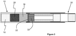
- FIG. 1 shows an electrically heated aerosol-generating system 10 in accordance with the present invention.
- the system 10 comprises a tubular housing 12 having an opening 14 at one end for receiving an aerosol-forming article.
- a substantially cylindrical heater element 16 At the opposite end of the tubular housing 12 is a substantially cylindrical heater element 16, a rechargeable battery 18 for powering the heater element 16, and control electronics 20 for controlling the operation of the system 10.
- the control electronics 20 control the switching on and off of the system 10, the power supplied from the rechargeable battery 18 to the heater element 16 and the charging of the rechargeable battery 18 when the battery is connected to an external power supply.
- a substantially circular end face 22 of the heater element 16 is covered by an aluminium patch 24 to provide efficient heat transfer from the heater element 16 into the upstream end of the aerosol-forming article.
- An aluminium sheath 26 lines the inner surface of the tubular housing 12 from the downstream end of the heater element 16 to the opening 14. The aluminium sheath 26 provides improved heat transfer from the heater element 16 towards the downstream end of the aerosol-forming article.
- An annular portion 28 of the aluminium patch 24 provides efficient heat transfer from the heater element 16 to the aluminium sheath 26.
- FIG 2 shows an aerosol-forming article 30 for use with the electrically operated aerosol-generating system 10 of Figure 1 .
- the aerosol-forming article 30 is a smoking article comprising a tobacco plug 32 provided at an upstream end of the article 30. Downstream of the tobacco plug 32 is an annular diffuser 34 that facilitates the formation of an aerosol from the tobacco plug 32 when the tobacco plug 32 is heated.
- a mouthpiece Downstream of the diffuser 34 is a mouthpiece comprising an upstream filter segment 36, a cavity 38 and a downstream filter segment 40.
- Each of the filter segments 36, 40 can comprise a conventional filter material, such as cellulose acetate.
- An outer wrapper 42 surrounds the components of the aerosol-forming article 30 to maintain the components in axial alignment and a tipping wrapper 44 is wrapped around the mouth end of the article 30 to provide an appearance similar to that of a conventional cigarette.
- Figure 3 shows the aerosol-forming article 30 inserted into the electrically operated aerosol-generating system 10.
- the tobacco plug 32 is positioned proximate the substantially circular end face 22 of the heater element 16 so that the tobacco plug 32 is heated to form an aerosol.
- a consumer draws on the mouth end of the article 30 to draw the aerosol through the article 30 and into the mouth.
- a number of air inlets may be provided in the tubular housing 12 to allow air to flow into the aerosol-generating system when the consumer draws on the mouth end of the article 30.
- the air inlets may be positioned such that they overly the tobacco plug 32 when the article 30 is fully inserted into the system 10.
- the air inlets may be positioned so that they overly the diffuser 34 when the article 30 is full inserted into the system 10.
- the diffuser 34 is preferably configured to direct incoming airflow upstream into the tobacco plug 32 before channelling the airflow from the tobacco plug 32 back through a central portion of the diffuser 34 towards the mouth end of the article 30.
- the control electronics 20 initialises the heater element 16 by passing a current from the rechargeable battery 18 through the heater element 16.
- the control electronics 20 monitors the temperature of the heater element 16 and maintains the current until a first temperature is reached. Upon reaching the first temperature the control electronics 20 reduces the current to the heater element 16 until the temperature of the heater element 16 drops to a second temperature. Once the temperature of the heater element 16 has reached the lower, second temperature the control electronics 20 continues to monitor the temperature of the heater element 16 and makes any necessary adjustments to the current supplied to the heater element 16 to maintain the second temperature.
- the control electronics 20 will switch off the supply of current to the heater element 16 after a predetermined period of time at which the article 30 is deemed consumed, or when the consumer stops puffing on the article 30 if sooner.
Claims (8)
- Système de génération d'aérosol chauffé électriquement (10) comprenant une partie tubulaire destinée à recevoir un article formant aérosol (30), un élément de chauffage (16) positionné à proximité d'une extrémité de la partie tubulaire, et une pile rechargeable (18) pour alimenter l'élément de chauffage (16), dans lequel l'élément de chauffage (16) comprend une face d'extrémité et un substrat thermoconducteur comprenant un revêtement anti-adhésif appliqué sur au moins une partie d'une surface externe du substrat thermoconducteur et au moins sur la face d'extrémité de l'élément de chauffage (16), et dans lequel le revêtement anti-adhésif inclut un matériau superhydrophobe.
- Système de génération d'aérosol chauffé électriquement (10) selon la revendication 1, dans lequel le revêtement non adhésif inclut du verre.
- Système de génération d'aérosol chauffé électriquement (10) selon les revendications 1 ou 2, dans lequel l'élément de chauffage (16) comprend un substrat thermoconducteur ayant une forme sensiblement cylindrique ou une forme de disque.
- Système de génération d'aérosol chauffé électriquement (10) selon les revendications 1 ou 2, dans lequel le substrat thermoconducteur comprend un métal ou une céramique électriquement conductrice.
- Système de génération d'aérosol chauffé électriquement (10) selon l'une quelconque des revendications précédentes, dans lequel la face d'extrémité (22) de l'élément de chauffage (16) est sensiblement circulaire.
- Système de génération d'aérosol chauffé électriquement (10) selon l'une quelconque des revendications précédentes, comprenant en outre une alimentation en énergie électrique (18) raccordée à l'élément de chauffage (16) pour chauffer de manière résistive l'élément de chauffage (16) lorsque le système (10) est activé.
- Système de génération d'aérosol chauffé électriquement (10) selon l'une quelconque des revendications précédentes, dans lequel l'élément de chauffage (16) est le seul élément de chauffage (16) dans le système (10).
- Système de génération d'aérosol chauffé électriquement (10) selon l'une quelconque des revendications précédentes, dans lequel le revêtement non adhésif inclut du polytétrafluoroéthylène (PTFE) .
Priority Applications (1)
| Application Number | Priority Date | Filing Date | Title |
|---|---|---|---|
| EP21195399.7A EP3935978A1 (fr) | 2014-05-21 | 2015-05-21 | Système de génération d'aérosol à chauffage électrique avec chauffage |
Applications Claiming Priority (3)
| Application Number | Priority Date | Filing Date | Title |
|---|---|---|---|
| EP14169342 | 2014-05-21 | ||
| EP15723967.4A EP3145339B1 (fr) | 2014-05-21 | 2015-05-21 | Système générateur d'aérosol chauffé électriquement ayant un dispositif de chauffage d'extrémité |
| PCT/EP2015/061318 WO2015177304A2 (fr) | 2014-05-21 | 2015-05-21 | Système générateur d'aérosol chauffé électriquement ayant un dispositif de chauffage d'extrémité |
Related Parent Applications (2)
| Application Number | Title | Priority Date | Filing Date |
|---|---|---|---|
| EP15723967.4A Division-Into EP3145339B1 (fr) | 2014-05-21 | 2015-05-21 | Système générateur d'aérosol chauffé électriquement ayant un dispositif de chauffage d'extrémité |
| EP15723967.4A Division EP3145339B1 (fr) | 2014-05-21 | 2015-05-21 | Système générateur d'aérosol chauffé électriquement ayant un dispositif de chauffage d'extrémité |
Related Child Applications (1)
| Application Number | Title | Priority Date | Filing Date |
|---|---|---|---|
| EP21195399.7A Division EP3935978A1 (fr) | 2014-05-21 | 2015-05-21 | Système de génération d'aérosol à chauffage électrique avec chauffage |
Publications (2)
| Publication Number | Publication Date |
|---|---|
| EP3363307A1 EP3363307A1 (fr) | 2018-08-22 |
| EP3363307B1 true EP3363307B1 (fr) | 2021-09-08 |
Family
ID=50732981
Family Applications (4)
| Application Number | Title | Priority Date | Filing Date |
|---|---|---|---|
| EP21195399.7A Pending EP3935978A1 (fr) | 2014-05-21 | 2015-05-21 | Système de génération d'aérosol à chauffage électrique avec chauffage |
| EP15723967.4A Active EP3145339B1 (fr) | 2014-05-21 | 2015-05-21 | Système générateur d'aérosol chauffé électriquement ayant un dispositif de chauffage d'extrémité |
| EP18166680.1A Active EP3363306B1 (fr) | 2014-05-21 | 2015-05-21 | Système de génération d'aérosol à chauffage électrique comportant un élément chauffant revêtu |
| EP18166682.7A Active EP3363307B1 (fr) | 2014-05-21 | 2015-05-21 | Système de génération d'aérosol à chauffage électrique comportant une face d'extrémité d'élément chauffant revêtu |
Family Applications Before (3)
| Application Number | Title | Priority Date | Filing Date |
|---|---|---|---|
| EP21195399.7A Pending EP3935978A1 (fr) | 2014-05-21 | 2015-05-21 | Système de génération d'aérosol à chauffage électrique avec chauffage |
| EP15723967.4A Active EP3145339B1 (fr) | 2014-05-21 | 2015-05-21 | Système générateur d'aérosol chauffé électriquement ayant un dispositif de chauffage d'extrémité |
| EP18166680.1A Active EP3363306B1 (fr) | 2014-05-21 | 2015-05-21 | Système de génération d'aérosol à chauffage électrique comportant un élément chauffant revêtu |
Country Status (9)
| Country | Link |
|---|---|
| US (2) | US11930566B2 (fr) |
| EP (4) | EP3935978A1 (fr) |
| JP (3) | JP6663357B2 (fr) |
| KR (3) | KR102513244B1 (fr) |
| CN (4) | CN106455708B (fr) |
| HK (2) | HK1259357A1 (fr) |
| PL (1) | PL3363306T3 (fr) |
| RU (3) | RU2675086C2 (fr) |
| WO (1) | WO2015177304A2 (fr) |
Families Citing this family (66)
| Publication number | Priority date | Publication date | Assignee | Title |
|---|---|---|---|---|
| US20160345631A1 (en) | 2005-07-19 | 2016-12-01 | James Monsees | Portable devices for generating an inhalable vapor |
| US10638792B2 (en) | 2013-03-15 | 2020-05-05 | Juul Labs, Inc. | Securely attaching cartridges for vaporizer devices |
| US10279934B2 (en) | 2013-03-15 | 2019-05-07 | Juul Labs, Inc. | Fillable vaporizer cartridge and method of filling |
| US10980273B2 (en) | 2013-11-12 | 2021-04-20 | VMR Products, LLC | Vaporizer, charger and methods of use |
| DE202014011221U1 (de) | 2013-12-23 | 2018-09-13 | Juul Labs Uk Holdco Limited | Systeme für eine Verdampfungsvorrichtung |
| US10076139B2 (en) | 2013-12-23 | 2018-09-18 | Juul Labs, Inc. | Vaporizer apparatus |
| US10058129B2 (en) | 2013-12-23 | 2018-08-28 | Juul Labs, Inc. | Vaporization device systems and methods |
| USD825102S1 (en) | 2016-07-28 | 2018-08-07 | Juul Labs, Inc. | Vaporizer device with cartridge |
| US10159282B2 (en) | 2013-12-23 | 2018-12-25 | Juul Labs, Inc. | Cartridge for use with a vaporizer device |
| US20160366947A1 (en) | 2013-12-23 | 2016-12-22 | James Monsees | Vaporizer apparatus |
| USD842536S1 (en) | 2016-07-28 | 2019-03-05 | Juul Labs, Inc. | Vaporizer cartridge |
| WO2015177304A2 (fr) | 2014-05-21 | 2015-11-26 | Philip Morris Products S.A. | Système générateur d'aérosol chauffé électriquement ayant un dispositif de chauffage d'extrémité |
| AU2015357509B2 (en) | 2014-12-05 | 2021-05-20 | Juul Labs, Inc. | Calibrated dose control |
| WO2017139595A1 (fr) | 2016-02-11 | 2017-08-17 | Pax Labs, Inc. | Cartouche de vaporisateur remplissable et procédé de remplissage |
| US10405582B2 (en) | 2016-03-10 | 2019-09-10 | Pax Labs, Inc. | Vaporization device with lip sensing |
| US11207478B2 (en) * | 2016-03-25 | 2021-12-28 | Rai Strategic Holdings, Inc. | Aerosol production assembly including surface with micro-pattern |
| USD849996S1 (en) | 2016-06-16 | 2019-05-28 | Pax Labs, Inc. | Vaporizer cartridge |
| USD836541S1 (en) | 2016-06-23 | 2018-12-25 | Pax Labs, Inc. | Charging device |
| USD851830S1 (en) | 2016-06-23 | 2019-06-18 | Pax Labs, Inc. | Combined vaporizer tamp and pick tool |
| WO2018050449A1 (fr) * | 2016-09-15 | 2018-03-22 | Philip Morris Products S.A. | Dispositif à fumer électronique générant un aérosol |
| US10757978B2 (en) | 2016-09-15 | 2020-09-01 | Altria Client Services Llc | Electronic aerosol-generating smoking device |
| EP3750415B1 (fr) | 2016-12-16 | 2024-04-10 | KT&G Corporation | Procédé et appareil de génération de d'aérosol |
| KR20180114825A (ko) | 2017-04-11 | 2018-10-19 | 주식회사 케이티앤지 | 전자 담배 제어 방법 및 장치 |
| WO2018190590A2 (fr) * | 2017-04-11 | 2018-10-18 | 주식회사 케이티앤지 | Système de génération d'aérosol d'élément chauffant de préchauffage |
| US11771138B2 (en) | 2017-04-11 | 2023-10-03 | Kt&G Corporation | Aerosol generating device and method for providing smoking restriction function in aerosol generating device |
| US11622582B2 (en) | 2017-04-11 | 2023-04-11 | Kt&G Corporation | Aerosol generating device and method for providing adaptive feedback through puff recognition |
| CN114766739A (zh) | 2017-04-11 | 2022-07-22 | 韩国烟草人参公社 | 提供基于抽吸识别的适应性反馈的气溶胶生成设备及方法 |
| JP7082140B2 (ja) | 2017-04-11 | 2022-06-07 | ケーティー アンド ジー コーポレイション | パフ認識を介した適応的なフィードバックを提供するエアロゾル生成デバイス及びその方法 |
| JP6854361B2 (ja) | 2017-04-11 | 2021-04-07 | ケーティー・アンド・ジー・コーポレーション | 喫煙部材クリーニングデバイス及び喫煙部材システム |
| US11252999B2 (en) | 2017-04-11 | 2022-02-22 | Kt&G Corporation | Aerosol generating device |
| GB2561867B (en) | 2017-04-25 | 2021-04-07 | Nerudia Ltd | Aerosol delivery system |
| KR102216139B1 (ko) | 2017-04-28 | 2021-02-16 | 주식회사 케이티앤지 | 에어로졸 발생 방법 및 장치 |
| WO2018199504A1 (fr) * | 2017-04-28 | 2018-11-01 | 주식회사 케이티앤지 | Procédé et appareil de génération d'aérosol |
| CN116584696A (zh) | 2017-05-10 | 2023-08-15 | 菲利普莫里斯生产公司 | 与多个气溶胶形成基质一起使用的气溶胶生成制品、装置和系统 |
| US11297876B2 (en) * | 2017-05-17 | 2022-04-12 | Rai Strategic Holdings, Inc. | Aerosol delivery device |
| KR102035313B1 (ko) | 2017-05-26 | 2019-10-22 | 주식회사 케이티앤지 | 히터 조립체 및 이를 구비한 에어로졸 생성 장치 |
| EP3669676B1 (fr) * | 2017-06-09 | 2021-04-21 | Philip Morris Products S.A. | Système de production d'aérosols adaptable |
| CN107252139A (zh) * | 2017-07-20 | 2017-10-17 | 深圳市博迪科技开发有限公司 | 用于电子烟的周向加热式烘烤针及电子烟 |
| CN111227313A (zh) | 2017-08-09 | 2020-06-05 | 菲利普莫里斯生产公司 | 气溶胶生成装置和气溶胶生成系统 |
| WO2019031871A1 (fr) | 2017-08-09 | 2019-02-14 | 주식회사 케이티앤지 | Procédé et dispositif de commande de cigarette électronique |
| EP3666095A4 (fr) | 2017-08-09 | 2021-11-24 | KT&G Corporation | Dispositif de génération d'aérosol et procédé de régulation pour dispositif de génération d'aérosol |
| JP6959429B2 (ja) | 2017-09-06 | 2021-11-02 | ケーティー・アンド・ジー・コーポレーション | エアロゾル生成装置 |
| USD887632S1 (en) | 2017-09-14 | 2020-06-16 | Pax Labs, Inc. | Vaporizer cartridge |
| BR112020008345A2 (pt) | 2017-11-30 | 2020-11-03 | Philip Morris Products S.A. | dispositivo gerador de aerossol e método para controlar um aquecedor de um dispositivo gerador de aerossol |
| KR102386632B1 (ko) * | 2018-04-12 | 2022-04-13 | 주식회사 케이티앤지 | 에어로졸 발생 장치 |
| KR102369446B1 (ko) * | 2018-04-12 | 2022-03-02 | 주식회사 케이티앤지 | 에어로졸 발생 장치 |
| CN112312785A (zh) | 2018-06-07 | 2021-02-02 | 尤尔实验室有限公司 | 用于蒸发器装置的料盒 |
| US20210235762A1 (en) * | 2018-06-07 | 2021-08-05 | Philip Morris Products S.A. | Electrical heating assembly for heating an aerosol-forming substrate |
| CN108783602A (zh) * | 2018-06-27 | 2018-11-13 | 威滔电子科技(深圳)有限公司 | 控制气溶胶产生装置产生气溶胶的方法及装置 |
| GB201812498D0 (en) * | 2018-07-31 | 2018-09-12 | Nicoventures Holdings Ltd | Aerosol generation |
| CN109123798A (zh) * | 2018-09-13 | 2019-01-04 | 云南中烟工业有限责任公司 | 一种多段式加热不燃烧卷烟的气溶胶产生装置 |
| JP7204904B2 (ja) * | 2018-10-08 | 2023-01-16 | フィリップ・モーリス・プロダクツ・ソシエテ・アノニム | エアロゾル発生装置のためのヒーター組立品のヒーターシェル |
| EP3876761A1 (fr) | 2018-11-05 | 2021-09-15 | Juul Labs, Inc. | Cartouches pour dispositifs de vaporisation |
| CN109363244A (zh) * | 2018-11-09 | 2019-02-22 | 福建中烟工业有限责任公司 | 气溶胶发生装置及加热气溶胶发生基质的方法 |
| KR102194730B1 (ko) * | 2018-11-16 | 2020-12-23 | 주식회사 케이티앤지 | 제1히터 및 제2히터를 갖는 에어로졸 생성장치 및 에어로졸 생성장치의 제1히터 및 제2히터의 전력을 제어하는 방법 |
| KR102363395B1 (ko) * | 2018-11-30 | 2022-02-15 | 주식회사 케이티앤지 | 에어로졸 생성 물품 |
| DE212019000479U1 (de) * | 2019-02-28 | 2022-01-07 | British American Tobacco Italia S.P.A. | Rauchartikel |
| PL3711552T3 (pl) * | 2019-03-22 | 2023-10-23 | Imperial Tobacco Limited | Układ zastępujący palenie |
| EP3711589A1 (fr) * | 2019-03-22 | 2020-09-23 | Nerudia Limited | Système de substitution du tabac |
| EP3711517A1 (fr) * | 2019-03-22 | 2020-09-23 | Nerudia Limited | Système de substitution du tabac |
| EP3711551A1 (fr) * | 2019-03-22 | 2020-09-23 | Nerudia Limited | Système de substitution du tabac |
| KR102252458B1 (ko) | 2019-04-30 | 2021-05-14 | 주식회사 케이티앤지 | 에어로졸 생성 장치 및 그의 동작 방법 |
| EP4026399A1 (fr) * | 2019-09-06 | 2022-07-13 | JT International SA | Ensemble chauffage |
| US11789476B2 (en) | 2021-01-18 | 2023-10-17 | Altria Client Services Llc | Heat-not-burn (HNB) aerosol-generating devices including intra-draw heater control, and methods of controlling a heater |
| GB202101854D0 (en) * | 2021-02-10 | 2021-03-24 | Nicoventures Trading Ltd | Apparatus for heating aerosolisable material |
| TW202241282A (zh) * | 2021-04-23 | 2022-11-01 | 瑞士商傑太日煙國際股份有限公司 | 氣溶膠產生製品 |
Family Cites Families (50)
| Publication number | Priority date | Publication date | Assignee | Title |
|---|---|---|---|---|
| US3480461A (en) * | 1966-11-14 | 1969-11-25 | Hamlin Stevens Inc | Metal articles having polytetrafluoroethylene-coated pressing surfaces and methods of their manufacture |
| US4735217A (en) * | 1986-08-21 | 1988-04-05 | The Procter & Gamble Company | Dosing device to provide vaporized medicament to the lungs as a fine aerosol |
| US4922901A (en) * | 1988-09-08 | 1990-05-08 | R. J. Reynolds Tobacco Company | Drug delivery articles utilizing electrical energy |
| US5144962A (en) * | 1989-12-01 | 1992-09-08 | Philip Morris Incorporated | Flavor-delivery article |
| JPH03176990A (ja) | 1989-12-04 | 1991-07-31 | Munetoshi Hisamoto | 投込み湯沸器のための密閉形発熱体およびその製造方法 |
| US5080115A (en) * | 1990-07-19 | 1992-01-14 | Brown & Williamson Tobacco Corporation | Simulated smoking article |
| US5665262A (en) | 1991-03-11 | 1997-09-09 | Philip Morris Incorporated | Tubular heater for use in an electrical smoking article |
| US5388594A (en) | 1991-03-11 | 1995-02-14 | Philip Morris Incorporated | Electrical smoking system for delivering flavors and method for making same |
| US5591368A (en) | 1991-03-11 | 1997-01-07 | Philip Morris Incorporated | Heater for use in an electrical smoking system |
| US6626901B1 (en) | 1997-03-05 | 2003-09-30 | The Trustees Of Columbia University In The City Of New York | Electrothermal instrument for sealing and joining or cutting tissue |
| DE19709035A1 (de) | 1997-03-06 | 1998-09-24 | Hoechst Ag | Mischungen aus Duroplasten und oxidierten Polyarylensulfiden |
| DE29713866U1 (de) | 1997-08-04 | 1997-10-02 | Baesler Peter | Heißluftadapter auf Elektrobasis für Zigaretten |
| DE10112736B4 (de) | 2001-03-16 | 2004-07-08 | Adolf Illig Maschinenbau Gmbh & Co.Kg | Heizwalze für eine Heizeinrichtung zum Erwärmen einer Folienbahn aus thermoplastischem Kunststoff |
| DE10212045A1 (de) * | 2002-03-19 | 2003-10-09 | Hermann Josef Selt | Elektrisch zu betreibende Heizvorrichtung für Pfeifen und Inhalationsgeräte |
| US20060027555A1 (en) | 2004-06-25 | 2006-02-09 | Integral Technologies, Inc. | Low cost heating elements for cooking applications manufactured from conductive loaded resin-based materials |
| DE102004061883A1 (de) * | 2004-12-22 | 2006-07-06 | Vishay Electronic Gmbh | Heizeinrichtung für ein Inhalationsgerät, Inhalationsgerät und Erwärmungsverfahren |
| US20070074734A1 (en) * | 2005-09-30 | 2007-04-05 | Philip Morris Usa Inc. | Smokeless cigarette system |
| CN201067079Y (zh) | 2006-05-16 | 2008-06-04 | 韩力 | 仿真气溶胶吸入器 |
| JP2008035742A (ja) | 2006-08-03 | 2008-02-21 | British American Tobacco Pacific Corporation | 揮発装置 |
| US7726320B2 (en) * | 2006-10-18 | 2010-06-01 | R. J. Reynolds Tobacco Company | Tobacco-containing smoking article |
| AU2008288170C1 (en) * | 2007-08-10 | 2013-04-04 | Philip Morris Products S.A. | Distillation-based smoking article |
| EP2110033A1 (fr) * | 2008-03-25 | 2009-10-21 | Philip Morris Products S.A. | Procédé pour le contrôle de la formation de constituants de fumée dans un système électrique de génération d'aérosol |
| DE102009029768B4 (de) | 2009-06-18 | 2013-02-21 | Zetzig Ab | Vorrichtung zur Abgabe von Nikotin |
| EP2316286A1 (fr) * | 2009-10-29 | 2011-05-04 | Philip Morris Products S.A. | Système de fumage chauffé électriquement doté d'un chauffage amélioré |
| EP2327318A1 (fr) | 2009-11-27 | 2011-06-01 | Philip Morris Products S.A. | Système de fumage chauffé électriquement doté d'un chauffage interne ou externe |
| EP2338361A1 (fr) | 2009-12-23 | 2011-06-29 | Philip Morris Products S.A. | Chauffage allongé pour système de génération d'aérosol chauffé électriquement |
| EP2340729A1 (fr) * | 2009-12-30 | 2011-07-06 | Philip Morris Products S.A. | Chauffage amélioré pour système de génération d'aérosol chauffé électriquement |
| EP2454956A1 (fr) * | 2010-11-19 | 2012-05-23 | Philip Morris Products S.A. | Système de fumage chauffé électriquement comportant au moins deux unités |
| EP2460424A1 (fr) * | 2010-12-03 | 2012-06-06 | Philip Morris Products S.A. | Système de génération d'aérosol doté de prévention de fuites |
| EP2469969A1 (fr) | 2010-12-24 | 2012-06-27 | Philip Morris Products S.A. | Élément de chauffage de céramique réduit |
| UA112440C2 (uk) | 2011-06-02 | 2016-09-12 | Філіп Морріс Продактс С.А. | Спалиме джерело тепла для курильного виробу |
| KR101315296B1 (ko) * | 2011-06-20 | 2013-10-07 | 윤성훈 | 전자담배 |
| WO2012174677A1 (fr) | 2011-06-22 | 2012-12-27 | Zhang Chongguang | Cigarette inoffensive composée de tabac |
| WO2013009883A1 (fr) | 2011-07-11 | 2013-01-17 | Jay Kumar | Dispositif de vaporisation |
| EP2753859B1 (fr) * | 2011-09-06 | 2017-12-20 | British American Tobacco (Investments) Limited | Isolation |
| KR101600646B1 (ko) * | 2011-11-11 | 2016-03-07 | 주식회사 케이티앤지 | 향미 전달 기구 |
| EP2609821A1 (fr) | 2011-12-30 | 2013-07-03 | Philip Morris Products S.A. | Procédé et appareil pour nettoyer un élément de chauffage d'un dispositif de génération d'aérosol |
| WO2013138384A2 (fr) * | 2012-03-12 | 2013-09-19 | Uptoke Llc | Dispositif de vaporisation électronique et procédés d'utilisation |
| GB201207039D0 (en) | 2012-04-23 | 2012-06-06 | British American Tobacco Co | Heating smokeable material |
| EP2844090B1 (fr) * | 2012-04-30 | 2017-09-27 | Philip Morris Products S.a.s. | Appareil à combiner à plusieurs composants en deux parties |
| UA114327C2 (uk) * | 2012-07-04 | 2017-05-25 | Філіп Морріс Продактс С.А. | Спалиме джерело тепла з вдосконаленим зв'язувальним матеріалом |
| RU122000U1 (ru) * | 2012-07-18 | 2012-11-20 | Общество с ограниченной ответственностью "САМАРИН" | Электронная сигарета с изменяемым вкусом |
| TW201417729A (zh) * | 2012-09-04 | 2014-05-16 | Philip Morris Products Sa | 絕熱熱源 |
| PL2892370T3 (pl) | 2012-09-10 | 2017-05-31 | Ght Global Heating Technologies Ag | Urządzenie do odparowania płynu do inhalacji |
| HUE032696T2 (en) | 2012-09-11 | 2017-10-30 | Philip Morris Products Sa | Device and method for controlling electric heating element, limiting temperature |
| WO2014075209A1 (fr) | 2012-11-13 | 2014-05-22 | Liu Qiuming | Cigarette électronique et dispositif d'atomisation pour celle-ci |
| RU132318U1 (ru) | 2013-04-29 | 2013-09-20 | Андрей Олегович Козулин | Вэйпор (электронный ингалятор) |
| CN203424290U (zh) | 2013-07-17 | 2014-02-12 | 中国烟草总公司郑州烟草研究院 | 一种基于远红外加热的非燃烧型烟草抽吸装置 |
| CN103416852B (zh) | 2013-08-02 | 2016-09-28 | 湖北中烟工业有限责任公司 | 光能加热卷烟的吸烟系统 |
| WO2015177304A2 (fr) | 2014-05-21 | 2015-11-26 | Philip Morris Products S.A. | Système générateur d'aérosol chauffé électriquement ayant un dispositif de chauffage d'extrémité |
-
2015
- 2015-05-21 WO PCT/EP2015/061318 patent/WO2015177304A2/fr active Application Filing
- 2015-05-21 EP EP21195399.7A patent/EP3935978A1/fr active Pending
- 2015-05-21 RU RU2016149159A patent/RU2675086C2/ru active
- 2015-05-21 CN CN201580020463.7A patent/CN106455708B/zh active Active
- 2015-05-21 EP EP15723967.4A patent/EP3145339B1/fr active Active
- 2015-05-21 PL PL18166680T patent/PL3363306T3/pl unknown
- 2015-05-21 CN CN201810360775.8A patent/CN108542008A/zh active Pending
- 2015-05-21 EP EP18166680.1A patent/EP3363306B1/fr active Active
- 2015-05-21 CN CN202110577064.8A patent/CN113142659A/zh active Pending
- 2015-05-21 US US15/305,139 patent/US11930566B2/en active Active
- 2015-05-21 KR KR1020167028895A patent/KR102513244B1/ko active IP Right Grant
- 2015-05-21 KR KR1020237009481A patent/KR102638060B1/ko active IP Right Grant
- 2015-05-21 EP EP18166682.7A patent/EP3363307B1/fr active Active
- 2015-05-21 JP JP2016567995A patent/JP6663357B2/ja active Active
- 2015-05-21 KR KR1020247005055A patent/KR20240023452A/ko active Application Filing
- 2015-05-21 CN CN201810362563.3A patent/CN108523237A/zh active Pending
-
2018
- 2018-05-09 JP JP2018090665A patent/JP6796106B2/ja active Active
- 2018-05-09 JP JP2018090664A patent/JP6796105B2/ja active Active
- 2018-05-22 RU RU2018118774A patent/RU2771304C2/ru active
- 2018-05-22 RU RU2018118776A patent/RU2771302C2/ru active
-
2019
- 2019-01-31 HK HK19101724.0A patent/HK1259357A1/zh unknown
- 2019-01-31 HK HK19101721.3A patent/HK1259354A1/zh unknown
-
2023
- 2023-10-03 US US18/480,299 patent/US20240032155A1/en active Pending
Also Published As
Similar Documents
| Publication | Publication Date | Title |
|---|---|---|
| US20240032155A1 (en) | Electrically heated aerosol-generating system with end heater | |
| RU2720608C2 (ru) | Расширенный нагреватель и нагревательный узел для образующей аэрозоль системы | |
| AU2012364360B2 (en) | An aerosol generating device and system with improved airflow | |
| US9516899B2 (en) | Aerosol generating device with improved temperature distribution | |
| RU2719235C2 (ru) | Нагревательный блок для системы, генерирующей аэрозоль | |
| EA023394B1 (ru) | Удлиненный нагреватель для электронагреваемой системы генерирования аэрозоля | |
| NZ627174B2 (en) | An aerosol generating device and system with improved airflow |
Legal Events
| Date | Code | Title | Description |
|---|---|---|---|
| PUAI | Public reference made under article 153(3) epc to a published international application that has entered the european phase |
Free format text: ORIGINAL CODE: 0009012 |
|
| STAA | Information on the status of an ep patent application or granted ep patent |
Free format text: STATUS: THE APPLICATION HAS BEEN PUBLISHED |
|
| AC | Divisional application: reference to earlier application |
Ref document number: 3145339 Country of ref document: EP Kind code of ref document: P |
|
| AK | Designated contracting states |
Kind code of ref document: A1 Designated state(s): AL AT BE BG CH CY CZ DE DK EE ES FI FR GB GR HR HU IE IS IT LI LT LU LV MC MK MT NL NO PL PT RO RS SE SI SK SM TR |
|
| STAA | Information on the status of an ep patent application or granted ep patent |
Free format text: STATUS: REQUEST FOR EXAMINATION WAS MADE |
|
| 17P | Request for examination filed |
Effective date: 20190222 |
|
| RBV | Designated contracting states (corrected) |
Designated state(s): AL AT BE BG CH CY CZ DE DK EE ES FI FR GB GR HR HU IE IS IT LI LT LU LV MC MK MT NL NO PL PT RO RS SE SI SK SM TR |
|
| STAA | Information on the status of an ep patent application or granted ep patent |
Free format text: STATUS: EXAMINATION IS IN PROGRESS |
|
| 17Q | First examination report despatched |
Effective date: 20190617 |
|
| 17Q | First examination report despatched |
Effective date: 20190704 |
|
| REG | Reference to a national code |
Ref country code: HK Ref legal event code: DE Ref document number: 1259354 Country of ref document: HK |
|
| GRAP | Despatch of communication of intention to grant a patent |
Free format text: ORIGINAL CODE: EPIDOSNIGR1 |
|
| STAA | Information on the status of an ep patent application or granted ep patent |
Free format text: STATUS: GRANT OF PATENT IS INTENDED |
|
| RIC1 | Information provided on ipc code assigned before grant |
Ipc: H05B 3/42 20060101ALI20200928BHEP Ipc: A24F 47/00 20200101AFI20200928BHEP Ipc: H05B 3/48 20060101ALI20200928BHEP |
|
| INTG | Intention to grant announced |
Effective date: 20201030 |
|
| GRAJ | Information related to disapproval of communication of intention to grant by the applicant or resumption of examination proceedings by the epo deleted |
Free format text: ORIGINAL CODE: EPIDOSDIGR1 |
|
| STAA | Information on the status of an ep patent application or granted ep patent |
Free format text: STATUS: EXAMINATION IS IN PROGRESS |
|
| GRAP | Despatch of communication of intention to grant a patent |
Free format text: ORIGINAL CODE: EPIDOSNIGR1 |
|
| STAA | Information on the status of an ep patent application or granted ep patent |
Free format text: STATUS: GRANT OF PATENT IS INTENDED |
|
| INTC | Intention to grant announced (deleted) | ||
| RIC1 | Information provided on ipc code assigned before grant |
Ipc: A24F 47/00 20200101AFI20210226BHEP Ipc: H05B 3/48 20060101ALI20210226BHEP Ipc: A24F 40/50 20200101ALI20210226BHEP Ipc: A24F 40/46 20200101ALI20210226BHEP Ipc: H05B 3/42 20060101ALI20210226BHEP |
|
| INTG | Intention to grant announced |
Effective date: 20210324 |
|
| GRAS | Grant fee paid |
Free format text: ORIGINAL CODE: EPIDOSNIGR3 |
|
| GRAA | (expected) grant |
Free format text: ORIGINAL CODE: 0009210 |
|
| STAA | Information on the status of an ep patent application or granted ep patent |
Free format text: STATUS: THE PATENT HAS BEEN GRANTED |
|
| AC | Divisional application: reference to earlier application |
Ref document number: 3145339 Country of ref document: EP Kind code of ref document: P |
|
| AK | Designated contracting states |
Kind code of ref document: B1 Designated state(s): AL AT BE BG CH CY CZ DE DK EE ES FI FR GB GR HR HU IE IS IT LI LT LU LV MC MK MT NL NO PL PT RO RS SE SI SK SM TR |
|
| REG | Reference to a national code |
Ref country code: GB Ref legal event code: FG4D |
|
| REG | Reference to a national code |
Ref country code: AT Ref legal event code: REF Ref document number: 1427725 Country of ref document: AT Kind code of ref document: T Effective date: 20210915 Ref country code: CH Ref legal event code: EP |
|
| REG | Reference to a national code |
Ref country code: IE Ref legal event code: FG4D |
|
| REG | Reference to a national code |
Ref country code: DE Ref legal event code: R096 Ref document number: 602015073223 Country of ref document: DE |
|
| REG | Reference to a national code |
Ref country code: NL Ref legal event code: FP |
|
| REG | Reference to a national code |
Ref country code: LT Ref legal event code: MG9D |
|
| PG25 | Lapsed in a contracting state [announced via postgrant information from national office to epo] |
Ref country code: RS Free format text: LAPSE BECAUSE OF FAILURE TO SUBMIT A TRANSLATION OF THE DESCRIPTION OR TO PAY THE FEE WITHIN THE PRESCRIBED TIME-LIMIT Effective date: 20210908 Ref country code: SE Free format text: LAPSE BECAUSE OF FAILURE TO SUBMIT A TRANSLATION OF THE DESCRIPTION OR TO PAY THE FEE WITHIN THE PRESCRIBED TIME-LIMIT Effective date: 20210908 Ref country code: HR Free format text: LAPSE BECAUSE OF FAILURE TO SUBMIT A TRANSLATION OF THE DESCRIPTION OR TO PAY THE FEE WITHIN THE PRESCRIBED TIME-LIMIT Effective date: 20210908 Ref country code: ES Free format text: LAPSE BECAUSE OF FAILURE TO SUBMIT A TRANSLATION OF THE DESCRIPTION OR TO PAY THE FEE WITHIN THE PRESCRIBED TIME-LIMIT Effective date: 20210908 Ref country code: FI Free format text: LAPSE BECAUSE OF FAILURE TO SUBMIT A TRANSLATION OF THE DESCRIPTION OR TO PAY THE FEE WITHIN THE PRESCRIBED TIME-LIMIT Effective date: 20210908 Ref country code: NO Free format text: LAPSE BECAUSE OF FAILURE TO SUBMIT A TRANSLATION OF THE DESCRIPTION OR TO PAY THE FEE WITHIN THE PRESCRIBED TIME-LIMIT Effective date: 20211208 Ref country code: BG Free format text: LAPSE BECAUSE OF FAILURE TO SUBMIT A TRANSLATION OF THE DESCRIPTION OR TO PAY THE FEE WITHIN THE PRESCRIBED TIME-LIMIT Effective date: 20211208 Ref country code: LT Free format text: LAPSE BECAUSE OF FAILURE TO SUBMIT A TRANSLATION OF THE DESCRIPTION OR TO PAY THE FEE WITHIN THE PRESCRIBED TIME-LIMIT Effective date: 20210908 |
|
| REG | Reference to a national code |
Ref country code: AT Ref legal event code: MK05 Ref document number: 1427725 Country of ref document: AT Kind code of ref document: T Effective date: 20210908 |
|
| PG25 | Lapsed in a contracting state [announced via postgrant information from national office to epo] |
Ref country code: LV Free format text: LAPSE BECAUSE OF FAILURE TO SUBMIT A TRANSLATION OF THE DESCRIPTION OR TO PAY THE FEE WITHIN THE PRESCRIBED TIME-LIMIT Effective date: 20210908 Ref country code: GR Free format text: LAPSE BECAUSE OF FAILURE TO SUBMIT A TRANSLATION OF THE DESCRIPTION OR TO PAY THE FEE WITHIN THE PRESCRIBED TIME-LIMIT Effective date: 20211209 |
|
| PG25 | Lapsed in a contracting state [announced via postgrant information from national office to epo] |
Ref country code: AT Free format text: LAPSE BECAUSE OF FAILURE TO SUBMIT A TRANSLATION OF THE DESCRIPTION OR TO PAY THE FEE WITHIN THE PRESCRIBED TIME-LIMIT Effective date: 20210908 |
|
| PG25 | Lapsed in a contracting state [announced via postgrant information from national office to epo] |
Ref country code: IS Free format text: LAPSE BECAUSE OF FAILURE TO SUBMIT A TRANSLATION OF THE DESCRIPTION OR TO PAY THE FEE WITHIN THE PRESCRIBED TIME-LIMIT Effective date: 20220108 Ref country code: SM Free format text: LAPSE BECAUSE OF FAILURE TO SUBMIT A TRANSLATION OF THE DESCRIPTION OR TO PAY THE FEE WITHIN THE PRESCRIBED TIME-LIMIT Effective date: 20210908 Ref country code: SK Free format text: LAPSE BECAUSE OF FAILURE TO SUBMIT A TRANSLATION OF THE DESCRIPTION OR TO PAY THE FEE WITHIN THE PRESCRIBED TIME-LIMIT Effective date: 20210908 Ref country code: RO Free format text: LAPSE BECAUSE OF FAILURE TO SUBMIT A TRANSLATION OF THE DESCRIPTION OR TO PAY THE FEE WITHIN THE PRESCRIBED TIME-LIMIT Effective date: 20210908 Ref country code: PT Free format text: LAPSE BECAUSE OF FAILURE TO SUBMIT A TRANSLATION OF THE DESCRIPTION OR TO PAY THE FEE WITHIN THE PRESCRIBED TIME-LIMIT Effective date: 20220110 Ref country code: PL Free format text: LAPSE BECAUSE OF FAILURE TO SUBMIT A TRANSLATION OF THE DESCRIPTION OR TO PAY THE FEE WITHIN THE PRESCRIBED TIME-LIMIT Effective date: 20210908 Ref country code: EE Free format text: LAPSE BECAUSE OF FAILURE TO SUBMIT A TRANSLATION OF THE DESCRIPTION OR TO PAY THE FEE WITHIN THE PRESCRIBED TIME-LIMIT Effective date: 20210908 Ref country code: CZ Free format text: LAPSE BECAUSE OF FAILURE TO SUBMIT A TRANSLATION OF THE DESCRIPTION OR TO PAY THE FEE WITHIN THE PRESCRIBED TIME-LIMIT Effective date: 20210908 Ref country code: AL Free format text: LAPSE BECAUSE OF FAILURE TO SUBMIT A TRANSLATION OF THE DESCRIPTION OR TO PAY THE FEE WITHIN THE PRESCRIBED TIME-LIMIT Effective date: 20210908 |
|
| REG | Reference to a national code |
Ref country code: DE Ref legal event code: R097 Ref document number: 602015073223 Country of ref document: DE |
|
| PLBE | No opposition filed within time limit |
Free format text: ORIGINAL CODE: 0009261 |
|
| STAA | Information on the status of an ep patent application or granted ep patent |
Free format text: STATUS: NO OPPOSITION FILED WITHIN TIME LIMIT |
|
| PG25 | Lapsed in a contracting state [announced via postgrant information from national office to epo] |
Ref country code: DK Free format text: LAPSE BECAUSE OF FAILURE TO SUBMIT A TRANSLATION OF THE DESCRIPTION OR TO PAY THE FEE WITHIN THE PRESCRIBED TIME-LIMIT Effective date: 20210908 |
|
| 26N | No opposition filed |
Effective date: 20220609 |
|
| PG25 | Lapsed in a contracting state [announced via postgrant information from national office to epo] |
Ref country code: SI Free format text: LAPSE BECAUSE OF FAILURE TO SUBMIT A TRANSLATION OF THE DESCRIPTION OR TO PAY THE FEE WITHIN THE PRESCRIBED TIME-LIMIT Effective date: 20210908 |
|
| REG | Reference to a national code |
Ref country code: BE Ref legal event code: MM Effective date: 20220531 |
|
| PG25 | Lapsed in a contracting state [announced via postgrant information from national office to epo] |
Ref country code: MC Free format text: LAPSE BECAUSE OF FAILURE TO SUBMIT A TRANSLATION OF THE DESCRIPTION OR TO PAY THE FEE WITHIN THE PRESCRIBED TIME-LIMIT Effective date: 20210908 Ref country code: LU Free format text: LAPSE BECAUSE OF NON-PAYMENT OF DUE FEES Effective date: 20220521 |
|
| PG25 | Lapsed in a contracting state [announced via postgrant information from national office to epo] |
Ref country code: IE Free format text: LAPSE BECAUSE OF NON-PAYMENT OF DUE FEES Effective date: 20220521 |
|
| PG25 | Lapsed in a contracting state [announced via postgrant information from national office to epo] |
Ref country code: BE Free format text: LAPSE BECAUSE OF NON-PAYMENT OF DUE FEES Effective date: 20220531 |
|
| P01 | Opt-out of the competence of the unified patent court (upc) registered |
Effective date: 20230529 |
|
| PGFP | Annual fee paid to national office [announced via postgrant information from national office to epo] |
Ref country code: NL Payment date: 20230519 Year of fee payment: 9 Ref country code: IT Payment date: 20230522 Year of fee payment: 9 Ref country code: FR Payment date: 20230526 Year of fee payment: 9 Ref country code: DE Payment date: 20230519 Year of fee payment: 9 Ref country code: CH Payment date: 20230602 Year of fee payment: 9 |
|
| PGFP | Annual fee paid to national office [announced via postgrant information from national office to epo] |
Ref country code: GB Payment date: 20230524 Year of fee payment: 9 |
|
| PG25 | Lapsed in a contracting state [announced via postgrant information from national office to epo] |
Ref country code: HU Free format text: LAPSE BECAUSE OF FAILURE TO SUBMIT A TRANSLATION OF THE DESCRIPTION OR TO PAY THE FEE WITHIN THE PRESCRIBED TIME-LIMIT; INVALID AB INITIO Effective date: 20150521 |