EP3363273A1 - Système de machine agricole et procédé de planification de voies de circulation permettant de traiter une surface agricole - Google Patents
Système de machine agricole et procédé de planification de voies de circulation permettant de traiter une surface agricole Download PDFInfo
- Publication number
- EP3363273A1 EP3363273A1 EP18401015.5A EP18401015A EP3363273A1 EP 3363273 A1 EP3363273 A1 EP 3363273A1 EP 18401015 A EP18401015 A EP 18401015A EP 3363273 A1 EP3363273 A1 EP 3363273A1
- Authority
- EP
- European Patent Office
- Prior art keywords
- area
- agricultural
- partial
- lanes
- subdivision
- Prior art date
- Legal status (The legal status is an assumption and is not a legal conclusion. Google has not performed a legal analysis and makes no representation as to the accuracy of the status listed.)
- Withdrawn
Links
- 238000000034 method Methods 0.000 title claims abstract description 34
- 238000001514 detection method Methods 0.000 claims abstract description 13
- 238000003754 machining Methods 0.000 claims description 20
- 238000000926 separation method Methods 0.000 claims description 8
- 230000007704 transition Effects 0.000 description 7
- 230000007547 defect Effects 0.000 description 4
- 238000009826 distribution Methods 0.000 description 4
- 238000004364 calculation method Methods 0.000 description 3
- 239000003337 fertilizer Substances 0.000 description 3
- 230000006870 function Effects 0.000 description 3
- 230000001788 irregular Effects 0.000 description 3
- 238000005520 cutting process Methods 0.000 description 2
- 238000005457 optimization Methods 0.000 description 2
- 238000009331 sowing Methods 0.000 description 2
- 230000001143 conditioned effect Effects 0.000 description 1
- 238000010276 construction Methods 0.000 description 1
- 230000005611 electricity Effects 0.000 description 1
- 239000000446 fuel Substances 0.000 description 1
- 238000007726 management method Methods 0.000 description 1
- 210000002023 somite Anatomy 0.000 description 1
- 238000003892 spreading Methods 0.000 description 1
- 230000001960 triggered effect Effects 0.000 description 1
- XLYOFNOQVPJJNP-UHFFFAOYSA-N water Substances O XLYOFNOQVPJJNP-UHFFFAOYSA-N 0.000 description 1
Images


Classifications
-
- A—HUMAN NECESSITIES
- A01—AGRICULTURE; FORESTRY; ANIMAL HUSBANDRY; HUNTING; TRAPPING; FISHING
- A01B—SOIL WORKING IN AGRICULTURE OR FORESTRY; PARTS, DETAILS, OR ACCESSORIES OF AGRICULTURAL MACHINES OR IMPLEMENTS, IN GENERAL
- A01B69/00—Steering of agricultural machines or implements; Guiding agricultural machines or implements on a desired track
-
- G—PHYSICS
- G05—CONTROLLING; REGULATING
- G05D—SYSTEMS FOR CONTROLLING OR REGULATING NON-ELECTRIC VARIABLES
- G05D1/00—Control of position, course or altitude of land, water, air, or space vehicles, e.g. automatic pilot
- G05D1/02—Control of position or course in two dimensions
- G05D1/021—Control of position or course in two dimensions specially adapted to land vehicles
- G05D1/0212—Control of position or course in two dimensions specially adapted to land vehicles with means for defining a desired trajectory
- G05D1/0219—Control of position or course in two dimensions specially adapted to land vehicles with means for defining a desired trajectory ensuring the processing of the whole working surface
-
- G—PHYSICS
- G05—CONTROLLING; REGULATING
- G05D—SYSTEMS FOR CONTROLLING OR REGULATING NON-ELECTRIC VARIABLES
- G05D1/00—Control of position, course or altitude of land, water, air, or space vehicles, e.g. automatic pilot
- G05D1/02—Control of position or course in two dimensions
- G05D1/021—Control of position or course in two dimensions specially adapted to land vehicles
- G05D1/0268—Control of position or course in two dimensions specially adapted to land vehicles using internal positioning means
- G05D1/0274—Control of position or course in two dimensions specially adapted to land vehicles using internal positioning means using mapping information stored in a memory device
Definitions
- the invention relates to an agricultural machine system according to the preamble of claim 1 and a method according to the preamble of claim 6.
- the processing of an agricultural area with an agricultural machine is generally carried out in rows. This means that with an agricultural implement such as a plow, the field is processed along parallel or nearly parallel lines whose distance depends on the working width of the implement.
- the parallel lanes are increasingly displayed on a terminal or other device to the operator, so that he can direct the device as precisely as possible along the intended tracks. An automatic steering along the parallel lanes is conceivable.
- the location, orientation and geometry of the lanes depends primarily on the working width of the machine and the field geometry. Depending on how the considered agricultural area is formed, it may be appropriate to subdivide these into sub-areas. Depending on the orientation of these partial surfaces, the processing direction of the respective partial surface will then be individually different for these partial surfaces, so that connecting movements between the partial surfaces or turning processes are optimized.
- a subdivision of a surface into several sub-areas is for example from the EP 2 446 725 B1 known. It is proposed to divide the area at or near concave nodes by connecting non-adjacent concave nodes. This procedure serves the purpose of carrying out a separate planning of the lanes for areas of the field which protrude from or protrude from a main area or first area of the field. The reason for this is that for very irregular formed agricultural surfaces, a single orientation of the machining direction may be inefficient because, for example, an unnecessarily high number of turning maneuvers must be performed.
- a disadvantage of this method is that only the angle size at the nodes, so the respective vertices, the agricultural area is considered to determine whether a partial surface is generated or not.
- this approach appears to be disadvantageous, for example, if no protruding part surface piece is generated by the concave nodes or a protruding part surface piece is not marked by the presence of one or in particular more concave nodes.
- Another method of dividing an agricultural area into sub-areas is from the DE 10 2014 108 075 A1 known. It is also proposed in this document to determine concave angles of the boundary of the agricultural area and to produce a dividing line which divides the agricultural area into at least two partial areas.
- the subdivision process takes place on the basis of optimization processes. For example, in the generation of the dividing line, a predetermined preferred orientation can be taken into account and this dividing line can be set parallel to this preferred orientation.
- the preferred orientation can be determined by means of optimization processes, for example by minimizing the processing wall in an unspecified manner or resorting to historical lane data.
- the pitch can be aligned parallel to an edge of the agricultural area or a maximum distance determined within the agricultural area and aligned the dividing line parallel to this maximum distance.
- a disadvantage of this method is that it is not determined whether at all concave nodes or, if not, at which concave nodes a subdivision of the agricultural area is to be made.
- the object of the present invention is to provide an agricultural machine system that overcomes the disadvantages of the prior art.
- the user can advantageously mark partial areas of the agricultural area, which should be considered separately for the planning of lanes. Only then are the lanes for each sub-area calculated separately.
- This approach is based on the finding that an advantageous division of an agricultural area for the planning of lanes can often not be fully automated, since a variety of geometries of areas are conceivable that make a division make sense, but where an automatic classification using uniform criteria not possible.
- a subjective assessment of the respective user often decides whether a surface should be subdivided into several sub-areas and processed separately or not. It is difficult to sufficiently anticipate the respective preferences of the user or to query in advance unambiguous criteria which make this possible.
- the modules can be installed on a terminal or, for example, the division of the area into partial areas can be carried out beforehand by means of a separate data processing system by the user. Also It is conceivable that a corresponding division is already stored in the terminal or at another location and merely called or transferred to this new. Thus, for example, for a particular agricultural area a division once made repeatedly called and used to determine the lanes for each sub-surface for each agricultural machine, for example, depending on machine parameters, such as minimum and / or maximum working width and / or minimal Machining radius, etc.
- the modules of the lane planning module described above can each be autonomously or partially autonomously supported in any combination, ie by user input, or run completely manually. Only the step of separating the respective subarea into subdivision surfaces takes place in any case at least partially autonomously, preferably fully automatically. Also preferably, the steps c) - g) in the specified alphabetical order.
- the method described here shows how the planning of lanes of an agricultural area can be particularly advantageous.
- the user first manually divides the agricultural area into partial areas, provided that this makes sense to the respective user.
- the preferred criterion here is whether different sub-areas with differently aligned reference axes allow a more efficient processing of the agricultural area than a complete processing of the agricultural area along a reference axis. For example, with an L-shaped surface, depending on the length of the legs of the surface be useful to edit them separately along two different, preferably along the legs oriented reference axes.
- the classification module can be executed before the direction module and the classification module determine the classification sections as a side section or headland section based on the respective geometry of the considered area or partial area.
- Arranged in front of the actual lane detection are therefore circular arcs in the transition region of two partial surfaces and / or subdivision surfaces, which are intended to enable a connection of the lanes of the adjacent partial surfaces and / or subdivision surfaces, so that along a first lane the processing of a first partial surface or subdivision surface occurs along the circular arc that connects tangentially to the first lane, the transition area is processed and then along a second lane, the agricultural area or partial area is processed, the second lane connects to the side of the circular arc, where the first lane is not connected.
- a transition region between two partial surfaces and / or subdivision surfaces can be processed advantageously whose lanes are not oriented parallel to each other.
- the partial surfaces do not adjoin one another on two side sections.
- the modules b) - i) are preferably suitable for processing the respective task at least partially autonomously.
- calculation steps are preferably carried out by the terminal and / or a correspondingly connected data processing system in order to provide optimized lane planning as a result.
- sectionautonom means here that the respective user confirms or discards an automatically determined indication, for example a suggestion for the selection of a reference axis or a headland range and in the latter case causes a new calculation with alternative parameters.
- the user selects a preferred one of several options that are at least approximately equivalent from the point of view of the system, for example when choosing a lane system, a reference axis or a headland area.
- the user is asked to enter certain parameters if the calculation of individual modules does not yield a result. For example, if no reference axis orientation could be determined, the user may be asked to manually select a reference axis.
- the working width in the form that the working width is always adapted to the respective distance of the lanes of the lane system at the respective location of the agricultural machine.
- the metering can be switched on and / or off at the corresponding positions in order to avoid double machining and / or defects.
- the distribution by means of the control of at least one actuator can be adjusted in such a way that double processing or incorrect applications and / or defects are avoided.
- one or more nozzles or sections can be switched on or off in a field sprayer and the distribution can be adjusted by changing the speed, dosing, task point and / or use of a border spreading device in a fertilizer spreader.
- the working width can be adjusted by means of a corresponding actuator, in particular a hydraulic cylinder.
- a method which initially allows a manual division of the agricultural surface into partial surfaces according to the individual view of the user, with a respective reference axis being defined for the agricultural surface or partial surface, which specifies the preferred processing direction within the respective partial surface , Then, sections of the boundary of the agricultural surface are classified as sections of the headland or side sections, depending on the orientation of the reference axis or the geometry of the surface or partial surface.
- the reference axis is in each case preferably at least approximately perpendicular the headland sections and is rather aligned parallel to the side sections. Subdivision surfaces are automatically created, these being applied explicitly on the basis of the orientation of adjacent sections, in particular headland and side sections, and / or based on the position of obstacles within the surface or subarea.
- the lane travel system is planned in particular separately for each partial area and / or subdivision area corresponding to the selected reference axes and / or side sections and / or headland areas.
- the lanes preferably run parallel to the respective reference axis of the partial surface or subdivision surface and run in the edge regions at least approximately parallel to the lateral sections.
- a lane tracking system in which the relative orientation of adjacent lanes may be adjusted to meet the above criteria, for example, when the respective face, patch, or subdivision surface is trapezoidal or otherwise irregular in shape.
- the lanes preferably run perpendicular to at least one headland area.
- a development of the method additionally includes the step of approaching the boundary of the agricultural area by means of a closed polygonal course.
- the limitation of the agricultural area and / or partial area and / or subdivision area is automatically approximated by means of a closed polygonal line in order to best determine the reference axes in the further course, optimally classify the individual sections of the polygon, the division of the area or partial areas in subdivision surfaces determine the headland areas and determine the lanes optimally.
- each Any contour of a surface can be approached by a closed polygon.
- FIG. 1 An inventive agricultural machine system is in Fig. 1 shown.
- the agricultural machine system here consists of a tractor 1 and a coupled to the tractor plow 2.
- the coupled plow is shown here as an example. It can also be attached to any other agricultural machine for processing an agricultural area to the tractor 1.
- the agricultural machine system can also be configured as a self-propelled agricultural machine system, for example a self-propelled sprayer or a combine harvester.
- the tractor 1 has a terminal 3, which can bring information to the driver of the tractor 1 by means of a display device, in particular information of the agricultural machine 2 and the tractor, such as position, speed, etc., displayed and operating parameters, such as the working width and / or working depth.
- the terminal 3 has operating elements in the form of switches, buttons and / or in particular a touch-sensitive screen.
- the terminal is in particular connected to one or more job computers 4, 5, which may be located on the tractor and / or the coupled agricultural machine.
- the data connection between the job computer 5 of the agricultural machine 2 and the job computer 4 of the tractor preferably takes place via a standardized data connection 6, in particular a so-called ISOBus interface.
- the terminal 3 can be connected directly to the job computer 5 of the agricultural machine 2 via the bus system, in particular the ISO bus.
- Information about the agricultural machine for example set actual values or sensor data, is transmitted to the job computer 4 or the terminal 3 via this bus system.
- control commands of the job computer 4 or terminals 3 are transmitted to the job computer 5 of the agricultural machine 2.
- the job computer 5 is connected to actuators and sensors via a data connection, for example with an actuator 9 for setting the cutting width of the plow 2.
- the job computer 5 of the agricultural machine 2 as part of a so-called TIM application (Tractor Implement Management) via the bus system 6 transmits control commands to the tractor 1. This can be done by the coupled machine 2, for example, a control command to reduce the speed or increase a three-point linkage to reduce the working depth. Such a measure can be triggered, for example, by corresponding sensor signals on the agricultural machine 2.
- the terminal 3 is now designed to determine lanes of agricultural land to be processed.
- the terminal has various modules for planning a desired lane system.
- the coordinates of the agricultural area are stored in a memory of the terminal 3. It can also be provided to start the outer contour of the agricultural area before planning the lanes and to record it by means of the terminal 3.
- a position receiver 7 is provided which is connected to the terminal 3 via the job computer 4.
- the position receiver 7, can also be connected directly to the terminal 3.
- the position receiver 7 may be formed for example as a GPS antenna.
- the modules for calculating the lane system are executed either on the terminal 3 or connected to the terminal job computer 4 and the lane system then displayed on the terminal only. It is also conceivable that the lane tracking system is determined on an external data processing system 8 and the lane data and field coordinates are transmitted to the terminal 3 or the job computer 4 by means of a data connection or a data carrier.
- the modules for planning the lane system are now executed on the terminal 3 or the job computer 4 or executed on the data processing system 8 and provided the lane tracking system the job computer 4 or Terminal 3 available.
- the agricultural area will now be laid out along the Track system worked.
- the lane system is displayed on a screen of the terminal.
- the user can now control the tractor 1 along the displayed lanes and edit the field accordingly.
- the cutting width of the plow or working width of the agricultural machine is adjusted according to the distances of the lanes of the lane system at the current position.
- the machine system automatically determines and adjusts the working width of the agricultural machine according to the lane spacing at the current position of the machine system. For this purpose, corresponding control commands are transmitted from the terminal 3 or the job computer 4 to the job computer 5 of the agricultural machine 2, whereupon the job computer 5, if necessary, adjusts the working width of the plow 2 by means of the actuator 9 in the present example.
- the automatic adjustment of the working width can be realized for any agricultural machinery, which are controllable via a data link from the tractor 2, in particular, the working width of seed drill, sprayer or fertilizer spreaders can be adapted in this way to local conditions.
- the agricultural machine system partially or fully autonomously processed the agricultural area along the planned lane system.
- steering commands and / or control commands for adjusting the speed are output by the terminal 3 or the job computer 4, so that the tractor 1 processes the agricultural area along the lane system.
- the turning operations at the end or at the beginning of each lane can be automated in this way.
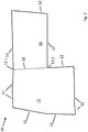
- Fig. 2 shows a schematic representation of an agricultural area 10.
- the geometry of this area can be stored in a memory of a data processing system, in particular of the terminal 3, the job computer 4 or the computer 8, as map data. It can, for example, the Geometry of the surface can be detected and stored by tracing and recording the contour by means of an agricultural implement or towing vehicle equipped with a GPS receiver.
- the agricultural towing vehicle 1 has a terminal 3 or the like, which is designed to display information and input parameters. On this terminal 3, for example, operation and status data of the agricultural machine can be displayed to a user, and machining parameters can be entered and changed.
- the terminal is also designed to indicate target lanes along which the agricultural area 10 is to be processed.
- the vehicle 1 can be steered autonomously or partially autonomously along the desired lane. This can be done by the terminal 3 or preferably connected to the terminal job computer 4, which is located on the towing vehicle 1 or attached to the towing vehicle device. At the same time, the current position and / or the actually traveled or actually processed area can be displayed on the terminal.
- the planning of the lanes can be carried out beforehand on an external data processing system 8 and transferred before the fieldwork or while on the terminal 3 or connected to the terminal job computer 4. Planning can also be made directly on Terminal 3.
- the user For the planning of the field work, it is advantageous to give the user the opportunity to divide the field into one or more faces at its discretion.
- the reason for this is that a separate processing of different field areas, especially if they have a longitudinal extension in different directions, can be more efficient.
- the orientation of the lanes should preferably be selected so that the lane length maximizes and / or the number of turns is minimized.
- a division of the agricultural area that fulfills these criteria can often be carried out very intuitively by a user, while an automation of this process is not possible for all conceivable field geometries.
- other criteria may be relevant to the user who may not be in the Terminal can be entered.
- the division of the field may be relevant to the division of the field at which point the user travels to the field before starting work and where he wants to leave it.
- it may play a role in the division of the field, as in the past the field was processed, for example, with which type of agricultural machine or in which direction the lanes in past work processes, such as plowing or sowing, was oriented.
- This information is the data processing device or the terminal, which is intended for planning the lane system may not be present.
- FIG Fig. 2 An agricultural surface 10, which can advantageously be divided, for example, into two partial surfaces 15, 16 is schematically shown in FIG Fig. 2 shown.
- the surface 10 is bounded by limiting sections 12. These boundary sections are shown as sections of a closed polygon.
- the field boundary may be stored in the data processing system or terminal as a polygon, or approximated by an algorithm as a polygon.
- the user has the option of dividing the agricultural area manually into several partial areas by means of a division module.
- a division module For this purpose, it marks, by means of an input device, for example on a touch screen of the terminal, two separating points 13.1 and 13.2 of the field boundary, which are to be connected by a dividing line 11.
- the dividing points 13.1 and 13.2 can be freely selectable or proposals can also be made for the selection of dividing points by the data processing system or terminal or the job computer, which the user can then select. These may each preferably be located between two sections of the traverse. Alternatively or additionally, the data processing system or terminal or the job computer can already suggest the division of partial areas.
- the partial surface 15 and 16 are marked independently.
- the user can then signal to the system that this area part is a partial area should be marked.
- this area part is a partial area should be marked.
- three possible faces have been proposed by the data processing system or terminal and if the user selects only one of these faces by touch or other input, only that face will be partitioned as a face in the manner suggested by the data processing system and the remainder of the agricultural face will be second Part surface treated.
- the dividing lines proposed by the data processing system, terminal or job computer can be adjusted in position and orientation preferably by the user after determining the partial areas.
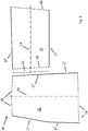
- the data processing system or job computer takes place automatically by means of a lane planning module, as in Fig. 3 and Fig. 4 shown.
- the lane planning module is in particular divided into further modules.
- the position of the reference axes 14 is determined by means of a directional module.
- the reference axes indicate the preferred machining direction during the machining of the respective partial surface 15, 16 and are determined individually for each partial surface 15, 16, preferably in accordance with the geometry of the respective partial surface.
- the reference axis may each be applied along the longest portion of the traverse.
- the sections of the traverse are then classified by the terminal or data processing system by means of a classification module preferably as headland sections 18, if they are at least predominantly perpendicular to the reference axis and as side sections 17, if they are at least predominantly parallel to the respective reference axis.
- the dividing line 11 is hereby assigned in each case as a section of the traverse to both partial surfaces 15 and 16, so that they are in turn bounded by a closed polygon.
- a classification of the sections of the traverse as a headland section 18 or side section 17 can also initially be carried out by means of the classification module.
- the sections of the traverse are defined as side sections 17 or headland sections 18 by the terminal or the data processing system or the job computer for each subarea.
- the headland sections are in this case placed at the points where due to the geometry of the respective partial surface turning of the agricultural machine in the processing of agricultural land is advantageous.
- the division is preferably carried out such that the number of lanes maximized and / or the number of turns is minimized.
- reference axes are now planned for each subarea 15, 16 by the data processing system or terminal by means of the directional module, which characterize the preferred machining direction within the respective subarea.
- These reference axes 14 preferably connect headland sections 18 on opposite sides of the respective sub-surface 15, 16, so that when processing along the respective reference axis 14 in the region of the headland sections 18 can be turned.
- the partial surfaces 15, 16 are divided into subdivision surfaces by the data processing system or terminal or job computer by means of a separation module, provided that the criteria stored for this purpose are met. For example, it may be provided that with a corresponding orientation and / or length and / or length ratio of adjacent headland and side portions, a division of the surface or respective partial surface is made, in particular, if the inner angle is greater than 180 °, since this bulges the agricultural area are characterized, which make a division of the agricultural area in several sub-areas advantageous.
- the size of these bulges can be characterized by the length of the considered headland and / or side section and also be taken into account. As the above criteria for the in Fig. 2-4 shown agricultural area 10 are not met, takes place for this surface or its partial surfaces 15, 16 no subdivision into subdivision surfaces.
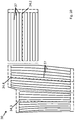
- headland areas of width d are determined by means of a headland module by the data processing system or terminal, as in Fig. 4 shown. These areas are excluded from machining along the lanes 19, 20 to be planned and used for the turning process at the end or at the beginning of the respective lane 19, 20.
- the width d of this area preferably depends on the turning radius of the respective towing vehicle and / or the agricultural processing device and / or its working width and / or the type of agricultural equipment used in each case, etc.
- the headland areas are each created in the area of the headland sections 18. However, it is not necessarily created by the data processing system or terminal or the job computer in each case a headland area on a headland section.
- a headland area on a headland section in the transition region of two partial surfaces can be provided that only a headland area is created when the adjoining sections of the partial surfaces 17.1 and 18.1 are classified as a headland section.
- a transition region of two partial surfaces can be processed particularly efficiently if a headland section 18.1 of a first partial surface adjoins a lateral segment 17.1 of a second partial surface.
- the second partial surface 16 must be processed first and the turning process at one end of the traffic lanes is then carried out in each case in the region of the first partial surface 15.
- the processing of the region in which the second partial surface 16 was processed is then carried out automatically. It can thus be saved a headland area, which leads to a more efficient processing of the surface 10 and thus less time and expense.
- the above-mentioned condition for the creation of a headland area at adjoining sections in the transitional area of two partial areas can also be linked to other conditions, for example, that only Then a headland area is created when in addition the reference axes include a certain angle, so that the lanes in the two areas can not be processed in one go, because, for example, a minimum machining radius of the agricultural machine is exceeded.
- a lane system for the area or subarea or subdivision area is created by the data processing system or terminal by means of a lane detection module.
- lanes 19.1, 19.2 are calculated for each partial surface and / or subdivision surface, which preferably extend at least approximately parallel to the respective reference axis 14.
- the course of the lanes is in this case adapted to the corresponding circumstances so that the lanes in the outer area or in the vicinity of obstacles to the respective sections, in particular side sections of the surface or partial surface or subdivision surface limiting polygonal hugging and so the most efficient processing of agricultural land possible is.
- the lane spacing preferably depends on the minimum and / or maximum working width and / or the minimum turning radius and / or minimum machining radius of the agricultural machine and / or the towing vehicle.
- the lanes end here in each case at a distance d from the respective headland section 18, provided that a headland area has been created in this area.
- a headland area has been created in this area.
- no headland area was created in the area of the headland section 18.1 of the partial surface 16.
- this area is turned in which was turned on the part surface 15 in the processing of the part surface 15 along the lanes 19.1.
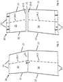
- a second agricultural area 20 is an application of the method according to the invention in Fig. 5 shown.
- the agricultural area 20 has been subdivided in this case by a user input in the division module such that a dividing line 21 results, which divides the surface 20 into partial surfaces 25 and 26.
- This division can also be proposed automatically by the distribution module, for example, and then accepted or rejected by the user.
- Each of the partial surfaces 25, 26 has a reference axis 24.1, 24.2, which are determined by the directional module in an automated manner.
- the reference axis 24.1 indicates a preferred machining direction in the upper region of the agricultural surface 20 and the reference axis 24.2 in the lower region.
- the reference axes are determined, for example, based on the orientation or geometry of the respectively considered area of the agricultural area. In each case, the orientation and length of the sections which bound the surface or partial area or subdivision surface can be considered for the respective surface or subarea or subdivision surface in order to determine the reference axis, so that the length of the traffic lanes is maximized and / or the number of turning operations is minimized.
- the agricultural area 20 is also bounded by side sections 22 and headland sections 23, which are determined by a classification module.
- the section or the dividing line 21 as a section 23.1 and 23.2 as each part of the sub-area 25 and 26, so that there is a closed traverse as a boundary for each of the sub-areas.
- the sections 23.1 and 23.2 are classified on the basis of their length and / or orientation in the present case in each case as a headland section.
- the classification of the sections in side sections and headland sections in this case takes place, for example, based on the angle which the respective reference axis and the considered section include or on the basis of the geometry of the respective partial surface 25, 26th
- the headland module now determines the position of the headland areas near the headland sections, where actually one or more lanes begin or end and thus a turning process is to take place.
- a range of width d of lanes kept free in which the turning process is to take place in which the turning process is to take place.
- no turning process should take place in the region of the parting line 21 of the partial surfaces 25, 26, no turning process should take place. Accordingly, no headland area is created there.
- the reference axes 24.1 and 24.2 include an angle ⁇ that is greater than a predetermined first critical angle.
- the first limit angle may preferably be determined by parameters of the agricultural machine and / or the tractor, for example by a minimum machining radius. The angle ⁇ is therefore so large that the lanes in the transition region of the partial surfaces 25, 26 can be processed in one go, that is, without exposing and / or turning the agricultural machine.
- the lanes are now using the lane detection module automatically as in Fig. 7 determined, wherein preferably in the area 28 of the dividing line 21, first the position of the circular arcs for connecting the lanes 27 and 29 are determined and then the lanes 27 and 29 are generated such that the respective part surface 25, 26 by editing the agricultural area without Defects can be edited.
- the lanes are constructed so that the number of crossings is minimized and the lanes 27, 29 tangentially meet the circular arcs in the area 28, so that connected lanes 27, 29 arise, each of which an angle ⁇ einsc included, which is greater than one is defined first critical angle and thus the lanes can be processed in one go.
- the lanes are designed such that they run approximately parallel to the reference axis 24.1 and 24.2 and cling to the side portions 22 in the edge region.
- An automatic division of the agricultural area by means of a separation module is not necessary in an agricultural area 20. If this area had not been subdivided into subareas 25, 26 and the angle ⁇ was smaller than the corresponding first critical angle, an automatic division by means of a separating module is provided so that a headland is then created in the area of the subdivision line 21, since the area in this area Case can not be processed in one go and without suspending.
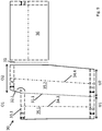
- a third agricultural area 30 is in Fig. 8 shown.
- the agricultural area has been divided by the user into two partial areas 35, 36 by construction of the dividing line 31.
- the subdivision may in this case be proposed by the apportionment module and accepted by the user or solely determined by manual selection of the position of the parting line by the user alone.
- the dividing line 31 is assigned in each case to both partial surfaces 35, 36, so that both partial surfaces are delimited by a closed polygon.
- a reference axis 34.1 and 34.2 is automatically determined for each subarea as the preferred processing direction for the respective subarea and classified by means of the classification module, the sections of the respective polygonal traction limiting the subarea in headland sections 33 and side sections 32.
- the sub-area 35 is subdivided into two subdivision areas 35. 1 and 35. 2, as in FIG Fig. 9 shown.
- the internal angle between the headland section 33.1 and the side section 32.1 is greater than a fixed second limit angle, for example 185 °.
- a fixed second limit angle for example 185 °.
- a reference axis 34.3, 34.4 is now constructed for each subdivision surface 35.1, 35.2, which indicate a preferred machining direction within the respective subdivision surface.
- the subdivision line 31.1 is selected according to the length of the upper headland areas O1 and O2 such that the lower headland areas of the same subdivision area have the same length as possible.
- the dividing line is not simply perpendicular, but at an angle to vertical, so that U1 is approximately equal to O1 and U2 is approximately equal to 02.
- side sections which are contiguous to the dividing line of a surface or partial surface.
- the orientation of the dividing line will be chosen such that the angle between dividing line 31.1 and side section 32.1 has a value of ⁇ and is therefore greater than a first critical angle determined by the minimum working radius of the agricultural machine or a minimum turning radius of the agricultural machine or tractor or other parameters is given.
- the angle ⁇ would be correspondingly smaller and under certain circumstances would be less than the first limit angle.
- the individual modules for planning the lane system can be used here in different orders.
- the reference axes 34.1, 34.2 planned directly after the manual division and then the reference axes 34.3, 34.4 are determined by the automatic division into subdivision surfaces.
- a further determination of reference axes for the subdivision surfaces can be omitted and only one reference axis per subarea in this case, for example, a reference axis 34.2 for the subdivision surfaces 35.1 and 35.2.
- a determination of the reference axes can be made only after the determination of the subdivision surfaces.
- the classification of the sections of the traverses as side sections and headland sections would have to be done without prior determination of the reference axes.
- this is easily conceivable.
- an optimal classification of the sections in headland and side sections could be made.
- headland areas of width d which are kept free of the lane system to be determined and serve as turning areas for turning between the processing of two lanes.
- headland areas of width d are also kept free of the lane system to be determined and serve as turning areas for turning between the processing of two lanes.
- the region of the dividing line 31 is analogous to the procedure for the agricultural area 10th no headland area created because during the processing of the part surface 36 then takes place in the processing of the partial surface 35 and the subdivision surfaces 35.1 and 35.2, the processing of the area that was previously used for the turning process in the region of the dividing line 31.
- lanes 37 are automatically created for all subareas and subdivision surfaces, as in FIG Fig. 10 represented so that the surface 30 can be processed by the agricultural machine without flaws along the lanes 37.
- the lanes in this case run in the individual partial surfaces or subdivision surfaces at least approximately parallel to the reference axes 34.2, 34.3, 34.4 and approximately parallel to the lateral sections in the edge regions, so that the most efficient possible processing of the agricultural surface 30 takes place.
- the distance of the lanes is generally conditioned by the working width of the agricultural machine, wherein the number of crossings and thus the number of turning operations is minimized as possible.
- the headland areas remain free of lanes and are used for turning following the processing of the respective lane 37.
- the width d of the headland areas depends primarily on the minimum turning radius of the agricultural machine and / or the towing vehicle.
- the directional module can be applied before or after the classification module, depending on whether the orientation of the reference axis or the geometry of the surface or partial area for the classification is considered for the classification of the individual sections of the traverse. It is also conceivable to apply the directional module only after the separation module has been used, that is to say to fix the reference axes only when the division of the surface or partial surface into subdivision surfaces has already taken place.
- the directional module can also be used twice, once before using the classification module and once after using the separation module. For the lane detection module can thus either for each subarea is defined as a reference axis, or for each subarea and subdivision surface.
Applications Claiming Priority (1)
| Application Number | Priority Date | Filing Date | Title |
|---|---|---|---|
| DE102017103141.3A DE102017103141A1 (de) | 2017-02-16 | 2017-02-16 | Landwirtschaftliches Maschinensystem und Verfahren zur Planung von Fahrspuren zur Bearbeitung einer landwirtschaftlichen Fläche |
Publications (1)
| Publication Number | Publication Date |
|---|---|
| EP3363273A1 true EP3363273A1 (fr) | 2018-08-22 |
Family
ID=61569204
Family Applications (1)
| Application Number | Title | Priority Date | Filing Date |
|---|---|---|---|
| EP18401015.5A Withdrawn EP3363273A1 (fr) | 2017-02-16 | 2018-02-13 | Système de machine agricole et procédé de planification de voies de circulation permettant de traiter une surface agricole |
Country Status (2)
| Country | Link |
|---|---|
| EP (1) | EP3363273A1 (fr) |
| DE (1) | DE102017103141A1 (fr) |
Cited By (4)
| Publication number | Priority date | Publication date | Assignee | Title |
|---|---|---|---|---|
| EP3626041A1 (fr) * | 2018-09-24 | 2020-03-25 | CLAAS Tractor S.A.S. | Système de travail agricole |
| CN113848880A (zh) * | 2021-08-30 | 2021-12-28 | 中车大连电力牵引研发中心有限公司 | 一种基于改进Q-learning的农机路径优化方法 |
| US11212954B2 (en) * | 2019-05-08 | 2022-01-04 | Deere & Company | Apparatus and methods for field operations based on historical field operation data |
| CN115039561A (zh) * | 2022-06-30 | 2022-09-13 | 松灵机器人(深圳)有限公司 | 割草方法、装置、割草机器人以及存储介质 |
Families Citing this family (4)
| Publication number | Priority date | Publication date | Assignee | Title |
|---|---|---|---|---|
| DE102020109012A1 (de) | 2020-04-01 | 2021-10-07 | Horsch Leeb Application Systems Gmbh | Verfahren zur Fahrspurplanung einer landwirtschaftlichen Arbeitsmaschine |
| DE102020109018A1 (de) | 2020-04-01 | 2021-10-07 | Horsch Leeb Application Systems Gmbh | Verfahren zum Planen einer Arbeitsbreiteneinstellung einer landwirtschaftlichen Arbeitsmaschine |
| DE102020109013A1 (de) | 2020-04-01 | 2021-10-07 | Horsch Leeb Application Systems Gmbh | Verfahren zur Fahrspurplanung mehrerer landwirtschaftlicher Arbeitsmaschinen |
| DE102021114420A1 (de) | 2021-06-04 | 2022-12-08 | Horsch Maschinen Gmbh | Landwirtschaftliches Nutzfahrzeuggespann mit autonomer Zugmaschine |
Citations (5)
| Publication number | Priority date | Publication date | Assignee | Title |
|---|---|---|---|---|
| EP2446725B1 (fr) | 2010-10-26 | 2013-07-31 | Deere & Company | Système et procédé de détermination du chemin prévu d'un véhicule |
| EP2952081A1 (fr) * | 2014-06-06 | 2015-12-09 | CLAAS Selbstfahrende Erntemaschinen GmbH | Procédé de planification d'un post-traitement agricole |
| DE102014108536A1 (de) * | 2014-06-17 | 2015-12-17 | Claas E-Systems Kgaa Mbh & Co Kg | Verfahren zur Bestimmung von Sollfahrspuren |
| DE102014108075A1 (de) | 2014-06-06 | 2015-12-17 | Claas E-Systems Kgaa Mbh & Co Kg | Verfahren zur Unterteilung eines Ausgangsfeldes in Teilfelder |
| US20160174453A1 (en) * | 2014-07-29 | 2016-06-23 | Kubota Corporation | Work Vehicle Coordinating System |
Family Cites Families (5)
| Publication number | Priority date | Publication date | Assignee | Title |
|---|---|---|---|---|
| EP1602267A3 (fr) | 2004-04-06 | 2011-05-25 | CLAAS Selbstfahrende Erntemaschinen GmbH | Système de planification d'itinéraire pour machines de travail agricole |
| DE102006015203A1 (de) | 2006-03-30 | 2007-11-15 | Claas Selbstfahrende Erntemaschinen Gmbh | Verfahren zur Steuerung von landwirtschaftlichen Maschinensystemen |
| DE102006015204A1 (de) | 2006-03-30 | 2007-10-18 | Claas Selbstfahrende Erntemaschinen Gmbh | Verfahren zur Erstellung eines Routenplans für landwirtschaftliche Maschinensysteme |
| DE102006019216A1 (de) | 2006-04-21 | 2007-10-25 | Claas Selbstfahrende Erntemaschinen Gmbh | Verfahren zur Steuerung eines landwirtschaftlichen Maschinensystems |
| DE102008050460A1 (de) | 2008-10-08 | 2010-04-15 | Claas Selbstfahrende Erntemaschinen Gmbh | Verfahren zur Einsatzsteuerung von landwirtschaftlichen Maschinen |
-
2017
- 2017-02-16 DE DE102017103141.3A patent/DE102017103141A1/de active Pending
-
2018
- 2018-02-13 EP EP18401015.5A patent/EP3363273A1/fr not_active Withdrawn
Patent Citations (5)
| Publication number | Priority date | Publication date | Assignee | Title |
|---|---|---|---|---|
| EP2446725B1 (fr) | 2010-10-26 | 2013-07-31 | Deere & Company | Système et procédé de détermination du chemin prévu d'un véhicule |
| EP2952081A1 (fr) * | 2014-06-06 | 2015-12-09 | CLAAS Selbstfahrende Erntemaschinen GmbH | Procédé de planification d'un post-traitement agricole |
| DE102014108075A1 (de) | 2014-06-06 | 2015-12-17 | Claas E-Systems Kgaa Mbh & Co Kg | Verfahren zur Unterteilung eines Ausgangsfeldes in Teilfelder |
| DE102014108536A1 (de) * | 2014-06-17 | 2015-12-17 | Claas E-Systems Kgaa Mbh & Co Kg | Verfahren zur Bestimmung von Sollfahrspuren |
| US20160174453A1 (en) * | 2014-07-29 | 2016-06-23 | Kubota Corporation | Work Vehicle Coordinating System |
Cited By (7)
| Publication number | Priority date | Publication date | Assignee | Title |
|---|---|---|---|---|
| EP3626041A1 (fr) * | 2018-09-24 | 2020-03-25 | CLAAS Tractor S.A.S. | Système de travail agricole |
| US11343957B2 (en) | 2018-09-24 | 2022-05-31 | Claas Tractor Sas | Agricultural work system |
| US11212954B2 (en) * | 2019-05-08 | 2022-01-04 | Deere & Company | Apparatus and methods for field operations based on historical field operation data |
| US11825761B2 (en) | 2019-05-08 | 2023-11-28 | Deere & Company | Apparatus and methods for field operations based on historical field operation data |
| CN113848880A (zh) * | 2021-08-30 | 2021-12-28 | 中车大连电力牵引研发中心有限公司 | 一种基于改进Q-learning的农机路径优化方法 |
| CN113848880B (zh) * | 2021-08-30 | 2023-12-22 | 中车大连电力牵引研发中心有限公司 | 一种基于改进Q-learning的农机路径优化方法 |
| CN115039561A (zh) * | 2022-06-30 | 2022-09-13 | 松灵机器人(深圳)有限公司 | 割草方法、装置、割草机器人以及存储介质 |
Also Published As
| Publication number | Publication date |
|---|---|
| DE102017103141A1 (de) | 2018-08-16 |
Similar Documents
| Publication | Publication Date | Title |
|---|---|---|
| EP3363273A1 (fr) | Système de machine agricole et procédé de planification de voies de circulation permettant de traiter une surface agricole | |
| EP1839479B1 (fr) | Procédé destiné à la commande de systèmes de machines agricoles | |
| EP1616470B1 (fr) | Procédé et dispositif de guidage pour machine de travail agricole | |
| EP2221702B1 (fr) | Procédé de production de bandes de circulation de référence pour des véhicules agricoles | |
| DE102004027242A1 (de) | Routenplanungssystem für landwirtschaftliche Arbeitsmaschinen | |
| EP2918157B2 (fr) | Machine agricole dotée d'une commande de section | |
| EP2921050B1 (fr) | Procédé d'épandage de produits phytosanitaires | |
| EP1602267A2 (fr) | Système de planification d'itinéraire pour machines de travail agricole | |
| EP3595427B1 (fr) | Procédé pour planifier le travail d'un champ agricole | |
| EP2236020B2 (fr) | Procédé et système de navigation pour machine agricole | |
| WO2020182564A1 (fr) | Système d'aide au pilotage basé sur la vision pour des véhicules terrestres | |
| EP2918155B1 (fr) | Procédé et unité de commande destinés au réglage d'une largeur de travail d'une charrue | |
| EP3732945A1 (fr) | Technique de la génération d'un profil de terrain à l'aide d'une machine agricole | |
| DE102017103138A1 (de) | Verfahren zur Bestimmung von Fahrspuren auf einer landwirtschaftlichen Fläche | |
| EP3014969B1 (fr) | Procédé de commande d'un épandeur agricole sur une surface agricole | |
| DE102022201888A1 (de) | Einrichtung und verfahren zum begrenzen der bewegung einer arbeitsmaschine | |
| EP2710873B1 (fr) | Dispositif de commande pour une machine de travail agricole | |
| DE102017103144A1 (de) | Verfahren und Vorrichtung zur Klassifizierung von Begrenzungsabschnitten einer landwirtschaftlichen Fläche | |
| DE102017103142A1 (de) | Verfahren zur Aufteilung einer landwirtschaftlichen Fläche in mehrere Teilflächen | |
| EP4331356A1 (fr) | Machine de répartition agricole dotée d'une rampe de pulvérisation et procédé de commande de la position d'une telle rampe de pulvérisation | |
| DE102022107924A1 (de) | Verfahren zum Betreiben eines landwirtschaftlichen Maschinensystems und landwirtschaftliches Maschinensystem zum Bearbeiten einer landwirtschaftlichen Nutzfläche | |
| DE102017103137A1 (de) | Verfahren zur Ermittlung von Vorgewendepositionen für eine landwirtschaftliche Fläche | |
| DE102020116701A1 (de) | Sollwerteinstellung von mehreren Funktionsaggregaten | |
| DE102017103140A1 (de) | Verfahren und Vorrichtung zur Festlegung einer Bezugsachse auf einer landwirtschaftlichen Fläche | |
| EP4286589A1 (fr) | Machine automotrice de travail du sol et procédé de commande d'une machine automotrice de travail du sol et procédé de traitement du sol avec une ou plusieurs machines automotrices |
Legal Events
| Date | Code | Title | Description |
|---|---|---|---|
| PUAI | Public reference made under article 153(3) epc to a published international application that has entered the european phase |
Free format text: ORIGINAL CODE: 0009012 |
|
| AK | Designated contracting states |
Kind code of ref document: A1 Designated state(s): AL AT BE BG CH CY CZ DE DK EE ES FI FR GB GR HR HU IE IS IT LI LT LU LV MC MK MT NL NO PL PT RO RS SE SI SK SM TR |
|
| AX | Request for extension of the european patent |
Extension state: BA ME |
|
| STAA | Information on the status of an ep patent application or granted ep patent |
Free format text: STATUS: THE APPLICATION IS DEEMED TO BE WITHDRAWN |
|
| 18D | Application deemed to be withdrawn |
Effective date: 20190223 |