EP3363273A1 - Agricultural machine system and method for planning lanes for processing an agricultural field - Google Patents
Agricultural machine system and method for planning lanes for processing an agricultural field Download PDFInfo
- Publication number
- EP3363273A1 EP3363273A1 EP18401015.5A EP18401015A EP3363273A1 EP 3363273 A1 EP3363273 A1 EP 3363273A1 EP 18401015 A EP18401015 A EP 18401015A EP 3363273 A1 EP3363273 A1 EP 3363273A1
- Authority
- EP
- European Patent Office
- Prior art keywords
- area
- agricultural
- partial
- lanes
- subdivision
- Prior art date
- Legal status (The legal status is an assumption and is not a legal conclusion. Google has not performed a legal analysis and makes no representation as to the accuracy of the status listed.)
- Withdrawn
Links
- 238000000034 method Methods 0.000 title claims abstract description 34
- 238000001514 detection method Methods 0.000 claims abstract description 13
- 238000003754 machining Methods 0.000 claims description 20
- 238000000926 separation method Methods 0.000 claims description 8
- 230000007704 transition Effects 0.000 description 7
- 230000007547 defect Effects 0.000 description 4
- 238000009826 distribution Methods 0.000 description 4
- 238000004364 calculation method Methods 0.000 description 3
- 239000003337 fertilizer Substances 0.000 description 3
- 230000006870 function Effects 0.000 description 3
- 230000001788 irregular Effects 0.000 description 3
- 238000005520 cutting process Methods 0.000 description 2
- 238000005457 optimization Methods 0.000 description 2
- 238000009331 sowing Methods 0.000 description 2
- 230000001143 conditioned effect Effects 0.000 description 1
- 238000010276 construction Methods 0.000 description 1
- 230000005611 electricity Effects 0.000 description 1
- 239000000446 fuel Substances 0.000 description 1
- 238000007726 management method Methods 0.000 description 1
- 210000002023 somite Anatomy 0.000 description 1
- 238000003892 spreading Methods 0.000 description 1
- 230000001960 triggered effect Effects 0.000 description 1
- XLYOFNOQVPJJNP-UHFFFAOYSA-N water Substances O XLYOFNOQVPJJNP-UHFFFAOYSA-N 0.000 description 1
Images


Classifications
-
- A—HUMAN NECESSITIES
- A01—AGRICULTURE; FORESTRY; ANIMAL HUSBANDRY; HUNTING; TRAPPING; FISHING
- A01B—SOIL WORKING IN AGRICULTURE OR FORESTRY; PARTS, DETAILS, OR ACCESSORIES OF AGRICULTURAL MACHINES OR IMPLEMENTS, IN GENERAL
- A01B69/00—Steering of agricultural machines or implements; Guiding agricultural machines or implements on a desired track
-
- G—PHYSICS
- G05—CONTROLLING; REGULATING
- G05D—SYSTEMS FOR CONTROLLING OR REGULATING NON-ELECTRIC VARIABLES
- G05D1/00—Control of position, course or altitude of land, water, air, or space vehicles, e.g. automatic pilot
- G05D1/02—Control of position or course in two dimensions
- G05D1/021—Control of position or course in two dimensions specially adapted to land vehicles
- G05D1/0212—Control of position or course in two dimensions specially adapted to land vehicles with means for defining a desired trajectory
- G05D1/0219—Control of position or course in two dimensions specially adapted to land vehicles with means for defining a desired trajectory ensuring the processing of the whole working surface
-
- G—PHYSICS
- G05—CONTROLLING; REGULATING
- G05D—SYSTEMS FOR CONTROLLING OR REGULATING NON-ELECTRIC VARIABLES
- G05D1/00—Control of position, course or altitude of land, water, air, or space vehicles, e.g. automatic pilot
- G05D1/02—Control of position or course in two dimensions
- G05D1/021—Control of position or course in two dimensions specially adapted to land vehicles
- G05D1/0268—Control of position or course in two dimensions specially adapted to land vehicles using internal positioning means
- G05D1/0274—Control of position or course in two dimensions specially adapted to land vehicles using internal positioning means using mapping information stored in a memory device
Definitions
- the invention relates to an agricultural machine system according to the preamble of claim 1 and a method according to the preamble of claim 6.
- the processing of an agricultural area with an agricultural machine is generally carried out in rows. This means that with an agricultural implement such as a plow, the field is processed along parallel or nearly parallel lines whose distance depends on the working width of the implement.
- the parallel lanes are increasingly displayed on a terminal or other device to the operator, so that he can direct the device as precisely as possible along the intended tracks. An automatic steering along the parallel lanes is conceivable.
- the location, orientation and geometry of the lanes depends primarily on the working width of the machine and the field geometry. Depending on how the considered agricultural area is formed, it may be appropriate to subdivide these into sub-areas. Depending on the orientation of these partial surfaces, the processing direction of the respective partial surface will then be individually different for these partial surfaces, so that connecting movements between the partial surfaces or turning processes are optimized.
- a subdivision of a surface into several sub-areas is for example from the EP 2 446 725 B1 known. It is proposed to divide the area at or near concave nodes by connecting non-adjacent concave nodes. This procedure serves the purpose of carrying out a separate planning of the lanes for areas of the field which protrude from or protrude from a main area or first area of the field. The reason for this is that for very irregular formed agricultural surfaces, a single orientation of the machining direction may be inefficient because, for example, an unnecessarily high number of turning maneuvers must be performed.
- a disadvantage of this method is that only the angle size at the nodes, so the respective vertices, the agricultural area is considered to determine whether a partial surface is generated or not.
- this approach appears to be disadvantageous, for example, if no protruding part surface piece is generated by the concave nodes or a protruding part surface piece is not marked by the presence of one or in particular more concave nodes.
- Another method of dividing an agricultural area into sub-areas is from the DE 10 2014 108 075 A1 known. It is also proposed in this document to determine concave angles of the boundary of the agricultural area and to produce a dividing line which divides the agricultural area into at least two partial areas.
- the subdivision process takes place on the basis of optimization processes. For example, in the generation of the dividing line, a predetermined preferred orientation can be taken into account and this dividing line can be set parallel to this preferred orientation.
- the preferred orientation can be determined by means of optimization processes, for example by minimizing the processing wall in an unspecified manner or resorting to historical lane data.
- the pitch can be aligned parallel to an edge of the agricultural area or a maximum distance determined within the agricultural area and aligned the dividing line parallel to this maximum distance.
- a disadvantage of this method is that it is not determined whether at all concave nodes or, if not, at which concave nodes a subdivision of the agricultural area is to be made.
- the object of the present invention is to provide an agricultural machine system that overcomes the disadvantages of the prior art.
- the user can advantageously mark partial areas of the agricultural area, which should be considered separately for the planning of lanes. Only then are the lanes for each sub-area calculated separately.
- This approach is based on the finding that an advantageous division of an agricultural area for the planning of lanes can often not be fully automated, since a variety of geometries of areas are conceivable that make a division make sense, but where an automatic classification using uniform criteria not possible.
- a subjective assessment of the respective user often decides whether a surface should be subdivided into several sub-areas and processed separately or not. It is difficult to sufficiently anticipate the respective preferences of the user or to query in advance unambiguous criteria which make this possible.
- the modules can be installed on a terminal or, for example, the division of the area into partial areas can be carried out beforehand by means of a separate data processing system by the user. Also It is conceivable that a corresponding division is already stored in the terminal or at another location and merely called or transferred to this new. Thus, for example, for a particular agricultural area a division once made repeatedly called and used to determine the lanes for each sub-surface for each agricultural machine, for example, depending on machine parameters, such as minimum and / or maximum working width and / or minimal Machining radius, etc.
- the modules of the lane planning module described above can each be autonomously or partially autonomously supported in any combination, ie by user input, or run completely manually. Only the step of separating the respective subarea into subdivision surfaces takes place in any case at least partially autonomously, preferably fully automatically. Also preferably, the steps c) - g) in the specified alphabetical order.
- the method described here shows how the planning of lanes of an agricultural area can be particularly advantageous.
- the user first manually divides the agricultural area into partial areas, provided that this makes sense to the respective user.
- the preferred criterion here is whether different sub-areas with differently aligned reference axes allow a more efficient processing of the agricultural area than a complete processing of the agricultural area along a reference axis. For example, with an L-shaped surface, depending on the length of the legs of the surface be useful to edit them separately along two different, preferably along the legs oriented reference axes.
- the classification module can be executed before the direction module and the classification module determine the classification sections as a side section or headland section based on the respective geometry of the considered area or partial area.
- Arranged in front of the actual lane detection are therefore circular arcs in the transition region of two partial surfaces and / or subdivision surfaces, which are intended to enable a connection of the lanes of the adjacent partial surfaces and / or subdivision surfaces, so that along a first lane the processing of a first partial surface or subdivision surface occurs along the circular arc that connects tangentially to the first lane, the transition area is processed and then along a second lane, the agricultural area or partial area is processed, the second lane connects to the side of the circular arc, where the first lane is not connected.
- a transition region between two partial surfaces and / or subdivision surfaces can be processed advantageously whose lanes are not oriented parallel to each other.
- the partial surfaces do not adjoin one another on two side sections.
- the modules b) - i) are preferably suitable for processing the respective task at least partially autonomously.
- calculation steps are preferably carried out by the terminal and / or a correspondingly connected data processing system in order to provide optimized lane planning as a result.
- sectionautonom means here that the respective user confirms or discards an automatically determined indication, for example a suggestion for the selection of a reference axis or a headland range and in the latter case causes a new calculation with alternative parameters.
- the user selects a preferred one of several options that are at least approximately equivalent from the point of view of the system, for example when choosing a lane system, a reference axis or a headland area.
- the user is asked to enter certain parameters if the calculation of individual modules does not yield a result. For example, if no reference axis orientation could be determined, the user may be asked to manually select a reference axis.
- the working width in the form that the working width is always adapted to the respective distance of the lanes of the lane system at the respective location of the agricultural machine.
- the metering can be switched on and / or off at the corresponding positions in order to avoid double machining and / or defects.
- the distribution by means of the control of at least one actuator can be adjusted in such a way that double processing or incorrect applications and / or defects are avoided.
- one or more nozzles or sections can be switched on or off in a field sprayer and the distribution can be adjusted by changing the speed, dosing, task point and / or use of a border spreading device in a fertilizer spreader.
- the working width can be adjusted by means of a corresponding actuator, in particular a hydraulic cylinder.
- a method which initially allows a manual division of the agricultural surface into partial surfaces according to the individual view of the user, with a respective reference axis being defined for the agricultural surface or partial surface, which specifies the preferred processing direction within the respective partial surface , Then, sections of the boundary of the agricultural surface are classified as sections of the headland or side sections, depending on the orientation of the reference axis or the geometry of the surface or partial surface.
- the reference axis is in each case preferably at least approximately perpendicular the headland sections and is rather aligned parallel to the side sections. Subdivision surfaces are automatically created, these being applied explicitly on the basis of the orientation of adjacent sections, in particular headland and side sections, and / or based on the position of obstacles within the surface or subarea.
- the lane travel system is planned in particular separately for each partial area and / or subdivision area corresponding to the selected reference axes and / or side sections and / or headland areas.
- the lanes preferably run parallel to the respective reference axis of the partial surface or subdivision surface and run in the edge regions at least approximately parallel to the lateral sections.
- a lane tracking system in which the relative orientation of adjacent lanes may be adjusted to meet the above criteria, for example, when the respective face, patch, or subdivision surface is trapezoidal or otherwise irregular in shape.
- the lanes preferably run perpendicular to at least one headland area.
- a development of the method additionally includes the step of approaching the boundary of the agricultural area by means of a closed polygonal course.
- the limitation of the agricultural area and / or partial area and / or subdivision area is automatically approximated by means of a closed polygonal line in order to best determine the reference axes in the further course, optimally classify the individual sections of the polygon, the division of the area or partial areas in subdivision surfaces determine the headland areas and determine the lanes optimally.
- each Any contour of a surface can be approached by a closed polygon.
- FIG. 1 An inventive agricultural machine system is in Fig. 1 shown.
- the agricultural machine system here consists of a tractor 1 and a coupled to the tractor plow 2.
- the coupled plow is shown here as an example. It can also be attached to any other agricultural machine for processing an agricultural area to the tractor 1.
- the agricultural machine system can also be configured as a self-propelled agricultural machine system, for example a self-propelled sprayer or a combine harvester.
- the tractor 1 has a terminal 3, which can bring information to the driver of the tractor 1 by means of a display device, in particular information of the agricultural machine 2 and the tractor, such as position, speed, etc., displayed and operating parameters, such as the working width and / or working depth.
- the terminal 3 has operating elements in the form of switches, buttons and / or in particular a touch-sensitive screen.
- the terminal is in particular connected to one or more job computers 4, 5, which may be located on the tractor and / or the coupled agricultural machine.
- the data connection between the job computer 5 of the agricultural machine 2 and the job computer 4 of the tractor preferably takes place via a standardized data connection 6, in particular a so-called ISOBus interface.
- the terminal 3 can be connected directly to the job computer 5 of the agricultural machine 2 via the bus system, in particular the ISO bus.
- Information about the agricultural machine for example set actual values or sensor data, is transmitted to the job computer 4 or the terminal 3 via this bus system.
- control commands of the job computer 4 or terminals 3 are transmitted to the job computer 5 of the agricultural machine 2.
- the job computer 5 is connected to actuators and sensors via a data connection, for example with an actuator 9 for setting the cutting width of the plow 2.
- the job computer 5 of the agricultural machine 2 as part of a so-called TIM application (Tractor Implement Management) via the bus system 6 transmits control commands to the tractor 1. This can be done by the coupled machine 2, for example, a control command to reduce the speed or increase a three-point linkage to reduce the working depth. Such a measure can be triggered, for example, by corresponding sensor signals on the agricultural machine 2.
- the terminal 3 is now designed to determine lanes of agricultural land to be processed.
- the terminal has various modules for planning a desired lane system.
- the coordinates of the agricultural area are stored in a memory of the terminal 3. It can also be provided to start the outer contour of the agricultural area before planning the lanes and to record it by means of the terminal 3.
- a position receiver 7 is provided which is connected to the terminal 3 via the job computer 4.
- the position receiver 7, can also be connected directly to the terminal 3.
- the position receiver 7 may be formed for example as a GPS antenna.
- the modules for calculating the lane system are executed either on the terminal 3 or connected to the terminal job computer 4 and the lane system then displayed on the terminal only. It is also conceivable that the lane tracking system is determined on an external data processing system 8 and the lane data and field coordinates are transmitted to the terminal 3 or the job computer 4 by means of a data connection or a data carrier.
- the modules for planning the lane system are now executed on the terminal 3 or the job computer 4 or executed on the data processing system 8 and provided the lane tracking system the job computer 4 or Terminal 3 available.
- the agricultural area will now be laid out along the Track system worked.
- the lane system is displayed on a screen of the terminal.
- the user can now control the tractor 1 along the displayed lanes and edit the field accordingly.
- the cutting width of the plow or working width of the agricultural machine is adjusted according to the distances of the lanes of the lane system at the current position.
- the machine system automatically determines and adjusts the working width of the agricultural machine according to the lane spacing at the current position of the machine system. For this purpose, corresponding control commands are transmitted from the terminal 3 or the job computer 4 to the job computer 5 of the agricultural machine 2, whereupon the job computer 5, if necessary, adjusts the working width of the plow 2 by means of the actuator 9 in the present example.
- the automatic adjustment of the working width can be realized for any agricultural machinery, which are controllable via a data link from the tractor 2, in particular, the working width of seed drill, sprayer or fertilizer spreaders can be adapted in this way to local conditions.
- the agricultural machine system partially or fully autonomously processed the agricultural area along the planned lane system.
- steering commands and / or control commands for adjusting the speed are output by the terminal 3 or the job computer 4, so that the tractor 1 processes the agricultural area along the lane system.
- the turning operations at the end or at the beginning of each lane can be automated in this way.
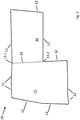
- Fig. 2 shows a schematic representation of an agricultural area 10.
- the geometry of this area can be stored in a memory of a data processing system, in particular of the terminal 3, the job computer 4 or the computer 8, as map data. It can, for example, the Geometry of the surface can be detected and stored by tracing and recording the contour by means of an agricultural implement or towing vehicle equipped with a GPS receiver.
- the agricultural towing vehicle 1 has a terminal 3 or the like, which is designed to display information and input parameters. On this terminal 3, for example, operation and status data of the agricultural machine can be displayed to a user, and machining parameters can be entered and changed.
- the terminal is also designed to indicate target lanes along which the agricultural area 10 is to be processed.
- the vehicle 1 can be steered autonomously or partially autonomously along the desired lane. This can be done by the terminal 3 or preferably connected to the terminal job computer 4, which is located on the towing vehicle 1 or attached to the towing vehicle device. At the same time, the current position and / or the actually traveled or actually processed area can be displayed on the terminal.
- the planning of the lanes can be carried out beforehand on an external data processing system 8 and transferred before the fieldwork or while on the terminal 3 or connected to the terminal job computer 4. Planning can also be made directly on Terminal 3.
- the user For the planning of the field work, it is advantageous to give the user the opportunity to divide the field into one or more faces at its discretion.
- the reason for this is that a separate processing of different field areas, especially if they have a longitudinal extension in different directions, can be more efficient.
- the orientation of the lanes should preferably be selected so that the lane length maximizes and / or the number of turns is minimized.
- a division of the agricultural area that fulfills these criteria can often be carried out very intuitively by a user, while an automation of this process is not possible for all conceivable field geometries.
- other criteria may be relevant to the user who may not be in the Terminal can be entered.
- the division of the field may be relevant to the division of the field at which point the user travels to the field before starting work and where he wants to leave it.
- it may play a role in the division of the field, as in the past the field was processed, for example, with which type of agricultural machine or in which direction the lanes in past work processes, such as plowing or sowing, was oriented.
- This information is the data processing device or the terminal, which is intended for planning the lane system may not be present.
- FIG Fig. 2 An agricultural surface 10, which can advantageously be divided, for example, into two partial surfaces 15, 16 is schematically shown in FIG Fig. 2 shown.
- the surface 10 is bounded by limiting sections 12. These boundary sections are shown as sections of a closed polygon.
- the field boundary may be stored in the data processing system or terminal as a polygon, or approximated by an algorithm as a polygon.
- the user has the option of dividing the agricultural area manually into several partial areas by means of a division module.
- a division module For this purpose, it marks, by means of an input device, for example on a touch screen of the terminal, two separating points 13.1 and 13.2 of the field boundary, which are to be connected by a dividing line 11.
- the dividing points 13.1 and 13.2 can be freely selectable or proposals can also be made for the selection of dividing points by the data processing system or terminal or the job computer, which the user can then select. These may each preferably be located between two sections of the traverse. Alternatively or additionally, the data processing system or terminal or the job computer can already suggest the division of partial areas.
- the partial surface 15 and 16 are marked independently.
- the user can then signal to the system that this area part is a partial area should be marked.
- this area part is a partial area should be marked.
- three possible faces have been proposed by the data processing system or terminal and if the user selects only one of these faces by touch or other input, only that face will be partitioned as a face in the manner suggested by the data processing system and the remainder of the agricultural face will be second Part surface treated.
- the dividing lines proposed by the data processing system, terminal or job computer can be adjusted in position and orientation preferably by the user after determining the partial areas.
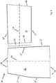
- the data processing system or job computer takes place automatically by means of a lane planning module, as in Fig. 3 and Fig. 4 shown.
- the lane planning module is in particular divided into further modules.
- the position of the reference axes 14 is determined by means of a directional module.
- the reference axes indicate the preferred machining direction during the machining of the respective partial surface 15, 16 and are determined individually for each partial surface 15, 16, preferably in accordance with the geometry of the respective partial surface.
- the reference axis may each be applied along the longest portion of the traverse.
- the sections of the traverse are then classified by the terminal or data processing system by means of a classification module preferably as headland sections 18, if they are at least predominantly perpendicular to the reference axis and as side sections 17, if they are at least predominantly parallel to the respective reference axis.
- the dividing line 11 is hereby assigned in each case as a section of the traverse to both partial surfaces 15 and 16, so that they are in turn bounded by a closed polygon.
- a classification of the sections of the traverse as a headland section 18 or side section 17 can also initially be carried out by means of the classification module.
- the sections of the traverse are defined as side sections 17 or headland sections 18 by the terminal or the data processing system or the job computer for each subarea.
- the headland sections are in this case placed at the points where due to the geometry of the respective partial surface turning of the agricultural machine in the processing of agricultural land is advantageous.
- the division is preferably carried out such that the number of lanes maximized and / or the number of turns is minimized.
- reference axes are now planned for each subarea 15, 16 by the data processing system or terminal by means of the directional module, which characterize the preferred machining direction within the respective subarea.
- These reference axes 14 preferably connect headland sections 18 on opposite sides of the respective sub-surface 15, 16, so that when processing along the respective reference axis 14 in the region of the headland sections 18 can be turned.
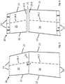
- the partial surfaces 15, 16 are divided into subdivision surfaces by the data processing system or terminal or job computer by means of a separation module, provided that the criteria stored for this purpose are met. For example, it may be provided that with a corresponding orientation and / or length and / or length ratio of adjacent headland and side portions, a division of the surface or respective partial surface is made, in particular, if the inner angle is greater than 180 °, since this bulges the agricultural area are characterized, which make a division of the agricultural area in several sub-areas advantageous.
- the size of these bulges can be characterized by the length of the considered headland and / or side section and also be taken into account. As the above criteria for the in Fig. 2-4 shown agricultural area 10 are not met, takes place for this surface or its partial surfaces 15, 16 no subdivision into subdivision surfaces.
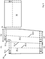
- headland areas of width d are determined by means of a headland module by the data processing system or terminal, as in Fig. 4 shown. These areas are excluded from machining along the lanes 19, 20 to be planned and used for the turning process at the end or at the beginning of the respective lane 19, 20.
- the width d of this area preferably depends on the turning radius of the respective towing vehicle and / or the agricultural processing device and / or its working width and / or the type of agricultural equipment used in each case, etc.
- the headland areas are each created in the area of the headland sections 18. However, it is not necessarily created by the data processing system or terminal or the job computer in each case a headland area on a headland section.
- a headland area on a headland section in the transition region of two partial surfaces can be provided that only a headland area is created when the adjoining sections of the partial surfaces 17.1 and 18.1 are classified as a headland section.
- a transition region of two partial surfaces can be processed particularly efficiently if a headland section 18.1 of a first partial surface adjoins a lateral segment 17.1 of a second partial surface.
- the second partial surface 16 must be processed first and the turning process at one end of the traffic lanes is then carried out in each case in the region of the first partial surface 15.
- the processing of the region in which the second partial surface 16 was processed is then carried out automatically. It can thus be saved a headland area, which leads to a more efficient processing of the surface 10 and thus less time and expense.
- the above-mentioned condition for the creation of a headland area at adjoining sections in the transitional area of two partial areas can also be linked to other conditions, for example, that only Then a headland area is created when in addition the reference axes include a certain angle, so that the lanes in the two areas can not be processed in one go, because, for example, a minimum machining radius of the agricultural machine is exceeded.
- a lane system for the area or subarea or subdivision area is created by the data processing system or terminal by means of a lane detection module.
- lanes 19.1, 19.2 are calculated for each partial surface and / or subdivision surface, which preferably extend at least approximately parallel to the respective reference axis 14.
- the course of the lanes is in this case adapted to the corresponding circumstances so that the lanes in the outer area or in the vicinity of obstacles to the respective sections, in particular side sections of the surface or partial surface or subdivision surface limiting polygonal hugging and so the most efficient processing of agricultural land possible is.
- the lane spacing preferably depends on the minimum and / or maximum working width and / or the minimum turning radius and / or minimum machining radius of the agricultural machine and / or the towing vehicle.
- the lanes end here in each case at a distance d from the respective headland section 18, provided that a headland area has been created in this area.
- a headland area has been created in this area.
- no headland area was created in the area of the headland section 18.1 of the partial surface 16.
- this area is turned in which was turned on the part surface 15 in the processing of the part surface 15 along the lanes 19.1.
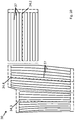
- a second agricultural area 20 is an application of the method according to the invention in Fig. 5 shown.
- the agricultural area 20 has been subdivided in this case by a user input in the division module such that a dividing line 21 results, which divides the surface 20 into partial surfaces 25 and 26.
- This division can also be proposed automatically by the distribution module, for example, and then accepted or rejected by the user.
- Each of the partial surfaces 25, 26 has a reference axis 24.1, 24.2, which are determined by the directional module in an automated manner.
- the reference axis 24.1 indicates a preferred machining direction in the upper region of the agricultural surface 20 and the reference axis 24.2 in the lower region.
- the reference axes are determined, for example, based on the orientation or geometry of the respectively considered area of the agricultural area. In each case, the orientation and length of the sections which bound the surface or partial area or subdivision surface can be considered for the respective surface or subarea or subdivision surface in order to determine the reference axis, so that the length of the traffic lanes is maximized and / or the number of turning operations is minimized.
- the agricultural area 20 is also bounded by side sections 22 and headland sections 23, which are determined by a classification module.
- the section or the dividing line 21 as a section 23.1 and 23.2 as each part of the sub-area 25 and 26, so that there is a closed traverse as a boundary for each of the sub-areas.
- the sections 23.1 and 23.2 are classified on the basis of their length and / or orientation in the present case in each case as a headland section.
- the classification of the sections in side sections and headland sections in this case takes place, for example, based on the angle which the respective reference axis and the considered section include or on the basis of the geometry of the respective partial surface 25, 26th
- the headland module now determines the position of the headland areas near the headland sections, where actually one or more lanes begin or end and thus a turning process is to take place.
- a range of width d of lanes kept free in which the turning process is to take place in which the turning process is to take place.
- no turning process should take place in the region of the parting line 21 of the partial surfaces 25, 26, no turning process should take place. Accordingly, no headland area is created there.
- the reference axes 24.1 and 24.2 include an angle ⁇ that is greater than a predetermined first critical angle.
- the first limit angle may preferably be determined by parameters of the agricultural machine and / or the tractor, for example by a minimum machining radius. The angle ⁇ is therefore so large that the lanes in the transition region of the partial surfaces 25, 26 can be processed in one go, that is, without exposing and / or turning the agricultural machine.
- the lanes are now using the lane detection module automatically as in Fig. 7 determined, wherein preferably in the area 28 of the dividing line 21, first the position of the circular arcs for connecting the lanes 27 and 29 are determined and then the lanes 27 and 29 are generated such that the respective part surface 25, 26 by editing the agricultural area without Defects can be edited.
- the lanes are constructed so that the number of crossings is minimized and the lanes 27, 29 tangentially meet the circular arcs in the area 28, so that connected lanes 27, 29 arise, each of which an angle ⁇ einsc included, which is greater than one is defined first critical angle and thus the lanes can be processed in one go.
- the lanes are designed such that they run approximately parallel to the reference axis 24.1 and 24.2 and cling to the side portions 22 in the edge region.
- An automatic division of the agricultural area by means of a separation module is not necessary in an agricultural area 20. If this area had not been subdivided into subareas 25, 26 and the angle ⁇ was smaller than the corresponding first critical angle, an automatic division by means of a separating module is provided so that a headland is then created in the area of the subdivision line 21, since the area in this area Case can not be processed in one go and without suspending.
- a third agricultural area 30 is in Fig. 8 shown.
- the agricultural area has been divided by the user into two partial areas 35, 36 by construction of the dividing line 31.
- the subdivision may in this case be proposed by the apportionment module and accepted by the user or solely determined by manual selection of the position of the parting line by the user alone.
- the dividing line 31 is assigned in each case to both partial surfaces 35, 36, so that both partial surfaces are delimited by a closed polygon.
- a reference axis 34.1 and 34.2 is automatically determined for each subarea as the preferred processing direction for the respective subarea and classified by means of the classification module, the sections of the respective polygonal traction limiting the subarea in headland sections 33 and side sections 32.
- the sub-area 35 is subdivided into two subdivision areas 35. 1 and 35. 2, as in FIG Fig. 9 shown.
- the internal angle between the headland section 33.1 and the side section 32.1 is greater than a fixed second limit angle, for example 185 °.
- a fixed second limit angle for example 185 °.
- a reference axis 34.3, 34.4 is now constructed for each subdivision surface 35.1, 35.2, which indicate a preferred machining direction within the respective subdivision surface.
- the subdivision line 31.1 is selected according to the length of the upper headland areas O1 and O2 such that the lower headland areas of the same subdivision area have the same length as possible.
- the dividing line is not simply perpendicular, but at an angle to vertical, so that U1 is approximately equal to O1 and U2 is approximately equal to 02.
- side sections which are contiguous to the dividing line of a surface or partial surface.
- the orientation of the dividing line will be chosen such that the angle between dividing line 31.1 and side section 32.1 has a value of ⁇ and is therefore greater than a first critical angle determined by the minimum working radius of the agricultural machine or a minimum turning radius of the agricultural machine or tractor or other parameters is given.
- the angle ⁇ would be correspondingly smaller and under certain circumstances would be less than the first limit angle.
- the individual modules for planning the lane system can be used here in different orders.
- the reference axes 34.1, 34.2 planned directly after the manual division and then the reference axes 34.3, 34.4 are determined by the automatic division into subdivision surfaces.
- a further determination of reference axes for the subdivision surfaces can be omitted and only one reference axis per subarea in this case, for example, a reference axis 34.2 for the subdivision surfaces 35.1 and 35.2.
- a determination of the reference axes can be made only after the determination of the subdivision surfaces.
- the classification of the sections of the traverses as side sections and headland sections would have to be done without prior determination of the reference axes.
- this is easily conceivable.
- an optimal classification of the sections in headland and side sections could be made.
- headland areas of width d which are kept free of the lane system to be determined and serve as turning areas for turning between the processing of two lanes.
- headland areas of width d are also kept free of the lane system to be determined and serve as turning areas for turning between the processing of two lanes.
- the region of the dividing line 31 is analogous to the procedure for the agricultural area 10th no headland area created because during the processing of the part surface 36 then takes place in the processing of the partial surface 35 and the subdivision surfaces 35.1 and 35.2, the processing of the area that was previously used for the turning process in the region of the dividing line 31.
- lanes 37 are automatically created for all subareas and subdivision surfaces, as in FIG Fig. 10 represented so that the surface 30 can be processed by the agricultural machine without flaws along the lanes 37.
- the lanes in this case run in the individual partial surfaces or subdivision surfaces at least approximately parallel to the reference axes 34.2, 34.3, 34.4 and approximately parallel to the lateral sections in the edge regions, so that the most efficient possible processing of the agricultural surface 30 takes place.
- the distance of the lanes is generally conditioned by the working width of the agricultural machine, wherein the number of crossings and thus the number of turning operations is minimized as possible.
- the headland areas remain free of lanes and are used for turning following the processing of the respective lane 37.
- the width d of the headland areas depends primarily on the minimum turning radius of the agricultural machine and / or the towing vehicle.
- the directional module can be applied before or after the classification module, depending on whether the orientation of the reference axis or the geometry of the surface or partial area for the classification is considered for the classification of the individual sections of the traverse. It is also conceivable to apply the directional module only after the separation module has been used, that is to say to fix the reference axes only when the division of the surface or partial surface into subdivision surfaces has already taken place.
- the directional module can also be used twice, once before using the classification module and once after using the separation module. For the lane detection module can thus either for each subarea is defined as a reference axis, or for each subarea and subdivision surface.
Abstract
Landwirtschaftliche Maschinensystem (1,2) und Verfahren zur Bearbeitung einer landwirtschaftlichen Fläche (10, 20, 30) mit einem Positionserfassungssystem (7) und einem landwirtschaftlichen Datenverarbeitungssystem (3), wobei die Geometrie der zu bearbeitenden landwirtschaftlichen Fläche (10, 20, 30) in dem Datenverarbeitungssystem hinterlegt ist, wobei das Datenverarbeitungssystem zur Ermittlung von Fahrspuren (19.1, 19.2, 29, 37) auf einer landwirtschaftlichen Fläche (10, 20, 30) ausgebildet ist, wobei das Datenverarbeitungssystem über folgende Module zur Bestimmung eines Fahrspursystems zur Bearbeitung der landwirtschaftlichen Fläche (10, 20, 30) verfügt: a) ein Aufteilungsmodul zur manuellen Teilung der landwirtschaftlichen Fläche in zumindest zwei Teilflächen (15, 16, 25, 26, 35, 36) durch einen Benutzer, falls eine separate Bearbeitung der Teilflächen sinnvoll erscheint, mittels einer Auswahl von Teilflächen und/oder einer Definition von Trennlinien (11, 21, 31) zur Aufteilung der landwirtschaftlichen Fläche in Teilflächen und b) ein Fahrspurplanungsmodul zur Ermittlung von Fahrspuren (19.1, 19.2, 29, 37) für die landwirtschaftliche Fläche und/oder jede Teilfläche.Agricultural machine system (1, 2) and method for processing an agricultural surface (10, 20, 30) with a position detection system (7) and an agricultural data processing system (3), the geometry of the agricultural surface (10, 20, 30) to be processed in the data processing system is deposited, wherein the data processing system for determining lanes (19.1, 19.2, 29, 37) on an agricultural area (10, 20, 30) is formed, wherein the data processing system via the following modules for determining a lane system for processing the agricultural Surface (10, 20, 30) features: a) a division module for manual division of the agricultural surface in at least two partial surfaces (15, 16, 25, 26, 35, 36) by a user, if a separate processing of the partial surfaces makes sense, by means of a selection of partial surfaces and / or a definition of dividing lines (11, 21, 31) for dividing the agricultural area into partial areas and b) a lane planning module for determining lanes (19.1, 19.2, 29, 37) for the agricultural area and / or each partial area.
Description
Die Erfindung betrifft ein landwirtschaftliches Maschinensystem gemäß dem Oberbegriff des Anspruchs 1 und ein Verfahren gemäß dem Oberbegriff des Anspruchs 6.The invention relates to an agricultural machine system according to the preamble of
Die Bearbeitung einer landwirtschaftlichen Fläche mit einer landwirtschaftlichen Maschine wird im Allgemeinen reihenweise durchgeführt. Das bedeutet, dass mit einem landwirtschaftlichen Gerät, beispielsweise einem Pflug, das Feld entlang paralleler oder annähernd paralleler Linien, deren Abstand von der Arbeitsbreite des Gerätes abhängt, bearbeitet wird. Um diese Arbeit möglichst effizient durchführen zu können, werden die parallelen Fahrspuren zunehmend auf einem Terminal oder sonstigen Gerät dem Bediener angezeigt, so dass dieser das Gerät möglichst präzise entlang der vorgesehenen Spuren lenken kann. Auch eine automatische Lenkung entlang der parallelen Fahrspuren ist denkbar.The processing of an agricultural area with an agricultural machine is generally carried out in rows. This means that with an agricultural implement such as a plow, the field is processed along parallel or nearly parallel lines whose distance depends on the working width of the implement. In order to perform this work as efficiently as possible, the parallel lanes are increasingly displayed on a terminal or other device to the operator, so that he can direct the device as precisely as possible along the intended tracks. An automatic steering along the parallel lanes is conceivable.
Die Lage, Ausrichtung und Geometrie der Fahrspuren hängt hierbei in erster Linie von der Arbeitsbreite der Maschine und der Feldgeometrie ab. Je nachdem, wie die betrachtete landwirtschaftliche Fläche geformt ist, kann es zweckmäßig sein, diese in Teilflächen zu unterteilen. Für diese Teilflächen wird dann zweckmäßigerweise, je nach Orientierung dieser Teilflächen auch die Bearbeitungsrichtung der jeweiligen Teilfläche individuell unterschiedlich sein, so dass Anschlussfahrten zwischen den Teilflächen oder Wendevorgänge optimiert werden.The location, orientation and geometry of the lanes depends primarily on the working width of the machine and the field geometry. Depending on how the considered agricultural area is formed, it may be appropriate to subdivide these into sub-areas. Depending on the orientation of these partial surfaces, the processing direction of the respective partial surface will then be individually different for these partial surfaces, so that connecting movements between the partial surfaces or turning processes are optimized.
Eine Unterteilung einer Fläche in mehrere Teilflächen ist beispielsweise aus der
Nachteilig an diesem Verfahren ist, dass allein die Winkelgröße an den Knoten, also den jeweiligen Eckpunkten, der landwirtschaftlichen Fläche betrachtet wird, um zu ermitteln, ob eine Teilfläche erzeugt wird oder nicht. Es sind ohne weiteres Feldgeometrien denkbar, bei denen diese Vorgehensweise nachteilbehaftet erscheint, beispielsweise, wenn durch die konkaven Knoten eben kein herausstehendes Teilflächenstück erzeugt wird oder ein herausstehendes Teilflächenstück nicht durch das Vorhandensein eines oder insbesondere mehrerer konkaver Knoten markiert wird.A disadvantage of this method is that only the angle size at the nodes, so the respective vertices, the agricultural area is considered to determine whether a partial surface is generated or not. There are readily conceivable field geometries in which this approach appears to be disadvantageous, for example, if no protruding part surface piece is generated by the concave nodes or a protruding part surface piece is not marked by the presence of one or in particular more concave nodes.
Ein weiteres Verfahren eine landwirtschaftliche Fläche in Teilflächen zu unterteilen ist aus der
Nachteilig an diesem Verfahren ist, dass nicht festgelegt ist, ob an allen konkaven Knoten oder falls nicht, an welchen konkaven Knoten eine Unterteilung der landwirtschaftlichen Fläche vorgenommen werden soll.A disadvantage of this method is that it is not determined whether at all concave nodes or, if not, at which concave nodes a subdivision of the agricultural area is to be made.
Aufgabe der vorliegenden Erfindung ist es, ein landwirtschaftliches Maschinensystem bereitzustellen, dass die Nachteile des Standes der Technik behebt.The object of the present invention is to provide an agricultural machine system that overcomes the disadvantages of the prior art.
Diese Aufgabe wird durch den kennzeichnenden Teil des Anspruchs 1 gelöst.This object is solved by the characterizing part of
Es wird also ein Datenverarbeitungssystem bereitgestellt, welches über folgende Module zur Bestimmung eines Fahrspursystems zur Bearbeitung der landwirtschaftlichen Fläche verfügt:
- a) ein Aufteilungsmodul zur manuellen Teilung der landwirtschaftlichen Fläche in zumindest zwei Teilflächen durch einen Benutzer, falls eine separate Bearbeitung der beiden Teilflächen sinnvoll erscheint, mittels einer Auswahl von Teilflächen und/oder einer Definition von Trennlinien zur Aufteilung der landwirtschaftlichen Fläche in Teilflächen und
- b) ein Fahrspurplanungsmodul zur Ermittlung von Fahrspuren für die landwirtschaftliche Fläche und/oder jede Teilfläche.
- a) a division module for manual division of the agricultural area in at least two sub-areas by a user, if a separate processing of the two sub-areas makes sense by means of a selection of sub-areas and / or a definition of dividing lines for dividing the agricultural area in sub-areas and
- b) a lane planning module for determining lanes for the agricultural area and / or each subarea.
Auf diese Weise kann der Benutzer in vorteilhafter Weise Teilflächen der landwirtschaftlichen Fläche markieren, welche für die Planung von Fahrspuren separat betrachtet werden sollen. Erst anschließend werden die Fahrspuren für jede Teilfläche separat berechnet. Dieser Vorgehensweise liegt die Erkenntnis zugrunde, dass ein vorteilhaftes Aufteilen einer landwirtschaftlichen Fläche für die Planung von Fahrspuren oftmals nicht vollständig automatisiert werden kann, da verschiedenste Geometrien von Flächen denkbar sind, die eine Aufteilung sinnvoll erscheinen lassen, bei denen jedoch eine automatische Klassifizierung mittels einheitlicher Kriterien nicht möglich ist. Zudem entscheidet oftmals eine subjektive Einschätzung des jeweiligen Benutzers, ob eine Fläche in mehrere Teilflächen unterteilt und separat bearbeitet werden soll oder nicht. Es ist schwierig die jeweiligen Vorlieben des Benutzers in ausreichender Weise zu antizipieren bzw. vorab eindeutige Kriterien abzufragen, die dieses ermöglichen.In this way, the user can advantageously mark partial areas of the agricultural area, which should be considered separately for the planning of lanes. Only then are the lanes for each sub-area calculated separately. This approach is based on the finding that an advantageous division of an agricultural area for the planning of lanes can often not be fully automated, since a variety of geometries of areas are conceivable that make a division make sense, but where an automatic classification using uniform criteria not possible. In addition, a subjective assessment of the respective user often decides whether a surface should be subdivided into several sub-areas and processed separately or not. It is difficult to sufficiently anticipate the respective preferences of the user or to query in advance unambiguous criteria which make this possible.
Die Module können auf einem Terminal installiert oder beispielsweise das Aufteilen der Fläche in Teilflächen vorab mittels eines separaten Datenverarbeitungssystems durch den Benutzer vorgenommen worden sein. Auch ist es denkbar, dass eine entsprechende Aufteilung bereits in dem Terminal oder an einem anderen Ort gespeichert und lediglich neu aufgerufen oder an dieses übertragen wird. So kann beispielsweise für eine jeweilige landwirtschaftliche Fläche eine einmal vorgenommene Aufteilung immer wieder aufgerufen und verwendet werden, um für die jeweilige landwirtschaftliche Maschine für jede Teilfläche die Fahrspuren zu ermitteln, beispielsweise in Abhängigkeit von Maschinenparametern, wie minimale und/oder maximale Arbeitsbreite und/oder minimaler Bearbeitungsradius usw.The modules can be installed on a terminal or, for example, the division of the area into partial areas can be carried out beforehand by means of a separate data processing system by the user. Also It is conceivable that a corresponding division is already stored in the terminal or at another location and merely called or transferred to this new. Thus, for example, for a particular agricultural area a division once made repeatedly called and used to determine the lanes for each sub-surface for each agricultural machine, for example, depending on machine parameters, such as minimum and / or maximum working width and / or minimal Machining radius, etc.
In einer bevorzugten Ausgestaltung der Erfindung umfasst das Fahrspurplanungsmodul:
- c) ein Richtungsmodul zur Ermittlung einer Bezugsachse als bevorzugte Bearbeitungsrichtung der landwirtschaftlichen Fläche oder jeweiligen Teilfläche in Abhängigkeit der Geometrie der landwirtschaftlichen Fläche oder Teilfläche,
- d) ein Klassifizierungsmodul zur Klassifizierung von Abschnitten der Begrenzung der landwirtschaftlichen Fläche oder einer Teilfläche in Abschnitte eines Vorgewendes oder Seitenabschnitte in Abhängigkeit von der Ausrichtung der Bezugsachse und/oder der Geometrie der landwirtschaftlichen Fläche oder Teilfläche,
- e) ein Separierungsmodul zur automatischen Aufteilung der landwirtschaftlichen Fläche oder Teilfläche in Unterteilungsflächen anhand der klassifizierten Abschnitte, wobei die Aufteilung der landwirtschaftlichen Fläche oder Teilfläche in Unterteilungsflächen anhand folgender Kriterien erfolgt:
- Orientierung und/oder Länge benachbarter Abschnitte, insbesondere benachbarter Vorgewende- und Seitenabschnitte und/oder,
- Position von Hindernissen innerhalb der Fläche oder Teilfläche,
- f) ein Vorgewendemodul zum Anlegen zumindest eines Vorgewendebereiches pro Teilfläche und/oder Unterteilungsfläche oder zweier Vorgewendebereiche pro landwirtschaftliche Fläche in Abhängigkeit der klassifizierten Abschnitte der Begrenzung der landwirtschaftlichen Fläche und/oder der ermittelten Bezugsachse für die landwirtschaftliche Fläche oder Teilfläche und
- g) ein Fahrspurermittlungsmodul zur Planung eines Fahrspursystems für die landwirtschaftliche Fläche und/oder zumindest eine Teilfläche und/oder Unterteilungsfläche anhand der ermittelten Bezugsachse, wobei die Fahrspuren zumindest annähernd parallel zu der jeweiligen Bezugsachse der Fläche oder Teilfläche verlaufen.
- Orientierung und/oder Länge benachbarter Abschnitte, insbesondere benachbarter Vorgewende- und Seitenabschnitte und/oder,
- Position von Hindernissen innerhalb der Fläche oder Teilfläche.
- c) a directional module for determining a reference axis as a preferred machining direction of the agricultural surface or respective partial surface depending on the geometry of the agricultural surface or partial surface,
- d) a classification module for classifying sections of the boundary of the agricultural area or a partial area into sections of a headland or side sections as a function of the orientation of the reference axis and / or the geometry of the agricultural area or partial area,
- (e) a separation module for automatically dividing the agricultural area or sub-area into subdivision areas on the basis of the classified sections, where the division of the agricultural area or subarea into subdivision areas is based on the following criteria:
- Orientation and / or length of adjacent sections, in particular adjacent headland and side sections and / or,
- Position of obstacles within the area or subarea,
- f) a headland module for applying at least one headland area per subarea and / or subdivision area or two headland areas per agricultural area depending on the classified portions of the boundary of agricultural area and / or the reference axis determined for the agricultural area or subarea, and
- g) a lane detection module for planning a lane system for the agricultural area and / or at least a partial area and / or subdivision surface based on the determined reference axis, wherein the lanes at least approximately parallel to the respective reference axis of the surface or partial surface.
- Orientation and / or length of adjacent sections, in particular adjacent headland and side sections and / or,
- Position of obstacles within the area or subarea.
Die vorab beschriebenen Module des Fahrspurplanungsmodules können jeweils in beliebiger Kombination autonom oder teilautonom, also durch Benutzereingaben unterstützt oder vollständig manuell ablaufen. Lediglich der Schritt des Separierens der jeweiligen Teilfläche in Unterteilungsflächen findet in jedem Fall zumindest teilautonom, bevorzugt vollautomatisch, statt. Ebenfalls bevorzugt laufen die Schritte c) - g) in der angegebenen alphabetischen Reihenfolge ab. Das hier beschriebene Verfahren zeigt auf, wie die Planung von Fahrspuren einer landwirtschaftlichen Fläche besonders vorteilhaft ablaufen kann. So wird zunächst durch den Benutzer manuell eine Einteilung der landwirtschaftlichen Fläche in Teilflächen vorgenommen, sofern dem jeweiligen Benutzer dies sinnvoll erscheint. Das bevorzugte Kriterium hierbei ist, ob verschiedene Teilflächen mit verschieden ausgerichteten Bezugsachsen eine effizientere Bearbeitung der landwirtschaftlichen Fläche ermöglichen, als eine komplette Bearbeitung der landwirtschaftlichen Fläche entlang einer Bezugsachse. So kann es beispielsweise bei einer L-förmigen Fläche je nach Länge der Schenkel der Fläche sinnvoll sein, diese separat entlang zweier unterschiedlich, bevorzugt entlang der Schenkel orientierter Bezugsachsen zu bearbeiten.The modules of the lane planning module described above can each be autonomously or partially autonomously supported in any combination, ie by user input, or run completely manually. Only the step of separating the respective subarea into subdivision surfaces takes place in any case at least partially autonomously, preferably fully automatically. Also preferably, the steps c) - g) in the specified alphabetical order. The method described here shows how the planning of lanes of an agricultural area can be particularly advantageous. Thus, the user first manually divides the agricultural area into partial areas, provided that this makes sense to the respective user. The preferred criterion here is whether different sub-areas with differently aligned reference axes allow a more efficient processing of the agricultural area than a complete processing of the agricultural area along a reference axis. For example, with an L-shaped surface, depending on the length of the legs of the surface be useful to edit them separately along two different, preferably along the legs oriented reference axes.
Es sind auch andere Reihenfolgen der Schritte c)- g) denkbar. So kann beispielsweise das Klassifizierungsmodul vor dem Richtungsmodul ausgeführt werden und das Klassifizierungsmodul die Klassifizierung Abschnitte als Seitenabschnitt oder Vorgewendeabschnitt anhand der jeweiligen Geometrie der betrachteten Fläche oder Teilfläche ermitteln.Other sequences of steps c) -g) are also conceivable. Thus, for example, the classification module can be executed before the direction module and the classification module determine the classification sections as a side section or headland section based on the respective geometry of the considered area or partial area.
In einer bevorzugten Weiterbildung der Erfindung umfasst das Fahrspurermittlungsmodul ferner ein
- h) Approximierungsmodul zur Annäherung der Begrenzung der landwirtschaftlichen Fläche und/oder Teilfläche und/oder Unterteilungsfläche mittels eines geschlossenen Polygonzuges.
- h) approximation module for approaching the boundary of the agricultural surface and / or partial surface and / or subdivision surface by means of a closed polygon.
In einer möglichen Weiterbildung der Erfindung umfasst das Fahrspurermittlungsmodul zudem ein
- i) Bogenschlussmodul zur Verbindung von Fahrspuren aneinander angrenzender Teilflächen und/oder Unterteilungsflächen mittels eines Bogenschlusses, wobei zu verbindende Fahrspuren sich an der Grenze benachbarter Teilflächen und/oder Unterteilungsflächen zumindest annähernd berühren oder schneiden, wobei der für den Bogenschluss zu konstruierende Kreisbogen bevorzugt jeweils tangential an die zu verbindenden Fahrspuren anschließt, wobei bevorzugt die Position der Kreisbögen ermittelt und erst anschließend die Fahrspuren derart konstruiert werden, dass sie tangential an den Kreisbogen anschließen.
- i) arcuate module for connecting lanes of adjoining subareas and / or subdivision surfaces by means of a bow closure, wherein lanes to be connected at least approximately touch or intersect at the boundary of adjacent subareas and / or subdivision surfaces, wherein the arc to be constructed for arcing preferably each tangent to connects the lanes to be connected, preferably the position of the circular arcs determined and only then the lanes are constructed so that they connect tangentially to the circular arc.
Es werden also bevorzugt vor der eigentlichen Fahrspurermittlung Kreisbögen im Übergangsbereich zweier Teilflächen und/oder Unterteilungsflächen geplant, welche eine Verbindung der Fahrspuren der benachbarten Teilflächen und/oder Unterteilungsflächen ermöglichen sollen, so dass entlang einer ersten Fahrspur die Bearbeitung einer ersten Teilfläche oder Unterteilungsfläche erfolgt, anschließend entlang des Kreisbogens, der tangential an die erste Fahrspur anschließt, der Übergangsbereich bearbeitet wird und dann entlang einer zweiten Fahrspur die landwirtschaftliche Fläche oder Teilfläche bearbeitet wird, wobei die zweite Fahrspur auf der Seite des Kreisbogen anschließt, an der die erste Fahrspur nicht anschließt. Auf diese Weise kann ein Übergangsbereich zwischen zwei Teilflächen und/oder Unterteilungsflächen vorteilhaft bearbeitet werden deren Fahrspuren nicht parallel zueinander orientiert sind. Die Teilflächen grenzen hierbei nicht an zwei Seitenabschnitten aneinander an. Bei der Ermittlung der Kreisbögen werden vorzugsweise Parameter der landwirtschaftlichen Maschine berücksichtigt, wie vorzugsweise minimale und/oder maximale Arbeitsbreite und/oder minimaler Bearbeitungsradius, welche den minimal zu befahrenden Radius während der Bearbeitung mit der landwirtschaftlichen Maschine angibt.Arranged in front of the actual lane detection are therefore circular arcs in the transition region of two partial surfaces and / or subdivision surfaces, which are intended to enable a connection of the lanes of the adjacent partial surfaces and / or subdivision surfaces, so that along a first lane the processing of a first partial surface or subdivision surface occurs along the circular arc that connects tangentially to the first lane, the transition area is processed and then along a second lane, the agricultural area or partial area is processed, the second lane connects to the side of the circular arc, where the first lane is not connected. In this way, a transition region between two partial surfaces and / or subdivision surfaces can be processed advantageously whose lanes are not oriented parallel to each other. The partial surfaces do not adjoin one another on two side sections. When determining the circular arcs, parameters of the agricultural machine are preferably taken into account, such as preferably minimum and / or maximum working width and / or minimum machining radius, which specifies the minimum radius to be traveled during processing with the agricultural machine.
Die Module b) - i) sind bevorzugt geeignet die jeweilige Aufgabe zumindest teilautonom zu bearbeiten. Es werden also bevorzugt jeweils Berechnungsschritte durch das Terminal und/oder ein entsprechend verbundenes Datenverarbeitungssystem durchgeführt, um im Ergebnis eine optimierte Fahrspurplanung bereitzustellen. Teilautonom meint hierbei, dass der jeweilige Benutzer eine automatisch ermittelte Angabe, beispielsweise einen Vorschlag für die Wahl einer Bezugsachse oder eines Vorgewendebereiches bestätigt oder verwirft und in letzterem Fall eine erneute Berechnung mit alternativen Parametern bewirkt. Alternativ kann vorgesehen sein, dass der Benutzer eine bevorzugte aus mehreren aus Sicht des Systems zumindest annähernd gleichwertigen Möglichkeiten auswählt, beispielsweise bei der Wahl eines Fahrspursystems, einer Bezugsachse oder eines Vorgewendebereichs. Es ist auch denkbar, dass der Benutzer um die Eingabe bestimmter Parameter gebeten wird, falls die Berechnung einzelner Module kein Ergebnis liefert. Beispielsweise wenn keine Bezugsachsenorientierung ermittelt werden konnte, kann der Benutzer um die manuelle Wahl einer Bezugsachse gebeten werden.The modules b) - i) are preferably suitable for processing the respective task at least partially autonomously. In each case, calculation steps are preferably carried out by the terminal and / or a correspondingly connected data processing system in order to provide optimized lane planning as a result. Teilautonom means here that the respective user confirms or discards an automatically determined indication, for example a suggestion for the selection of a reference axis or a headland range and in the latter case causes a new calculation with alternative parameters. Alternatively, it can be provided that the user selects a preferred one of several options that are at least approximately equivalent from the point of view of the system, for example when choosing a lane system, a reference axis or a headland area. It is also conceivable that the user is asked to enter certain parameters if the calculation of individual modules does not yield a result. For example, if no reference axis orientation could be determined, the user may be asked to manually select a reference axis.
In einer bevorzugten Ausgestaltung verfügt das Maschinensystem über eine mittels zumindest eines Aktors anpassbare Arbeitsbreite und umfasst zudem
- j) ein Arbeitsbreitenmodul, welches zur automatischen Anpassung der Arbeitsbreite an den Abstand zu einer benachbarten Fahrspur Stellsignale an den zumindest einen Aktor sendet, so dass keine unbearbeiteten Flächen übrig bleiben und möglichst keine Doppelbearbeitung oder Fehlbearbeitung erfolgt.
- j) a working width module which sends for automatic adjustment of the working width at the distance to an adjacent lane control signals to the at least one actuator, so that no unprocessed surfaces remain and possible no duplication or incorrect processing takes place.
Auf diese Weise kann vorteilhaft entlang der bearbeiteten Fahrspuren automatisiert eine Anpassung der Arbeitsbreite in der Form erfolgen, dass die Arbeitsbreite immer auf den jeweiligen Abstand der Fahrspuren des Fahrspursystems am jeweiligen Ort der landwirtschaftlichen Maschine angepasst ist. Insbesondere kann bei einer Sämaschine die Dosierung an den entsprechenden Positionen ein- und/oder ausgeschaltet werden, um Doppelbearbeitungen und/oder Fehlstellen zu vermeiden. Zudem kann bei einer beliebigen Verteilmaschine wie Feldspritze oder Düngerstreuer die Verteilung mittels der Ansteuerung zumindest eines Aktors in der Weise angepasst werden, dass Doppelbearbeitungen bzw. Fehlapplikationen und/oder Fehlstellen vermieden werden. Hierfür können bei einer Feldspritze beispielsweise ein oder mehrere Düsen oder Teilbreiten zu- oder abgeschaltet werden und bei einem Düngerstreuer die Verteilung mittels Änderung der Drehzahl, Dosiermenge, Aufgabepunkt und/oder Einsatz einer Grenzstreuvorrichtung angepasst werden. Bei einem Pflug kann beispielsweise vorgesehen sein die Arbeitsbreite mittels eines entsprechenden Aktors, insbesondere Hydraulikzylinders, anzupassen.In this way, can advantageously be carried out along the processed lanes automated adjustment of the working width in the form that the working width is always adapted to the respective distance of the lanes of the lane system at the respective location of the agricultural machine. In particular, in a sowing machine, the metering can be switched on and / or off at the corresponding positions in order to avoid double machining and / or defects. In addition, in any distribution machine such as field sprayer or fertilizer spreader, the distribution by means of the control of at least one actuator can be adjusted in such a way that double processing or incorrect applications and / or defects are avoided. For this purpose, for example, one or more nozzles or sections can be switched on or off in a field sprayer and the distribution can be adjusted by changing the speed, dosing, task point and / or use of a border spreading device in a fertilizer spreader. For example, in the case of a plow, the working width can be adjusted by means of a corresponding actuator, in particular a hydraulic cylinder.
Die vorliegende Anmeldung stellt zudem ein entsprechendes Verfahren zur Planung von Fahrspuren auf einer landwirtschaftlichen Fläche oder Teilfläche zur Bearbeitung der landwirtschaftlichen Fläche mittels einer landwirtschaftlichen Maschine entlang der geplanten Fahrspuren bereit, wobei das Verfahren gekennzeichnet ist durch folgende Schritte:
- k) Manuelles Aufteilen der landwirtschaftlichen Fläche in Teilflächen durch einen Benutzer, falls eine sukzessive Bearbeitung von Teilflächen der landwirtschaftlichen Fläche vorteilhaft erscheint,
- I) Ermitteln einer Bezugsachse als bevorzugte Bearbeitungsrichtung der landwirtschaftlichen Fläche oder jeweiligen Teilfläche in Abhängigkeit der Geometrie der landwirtschaftlichen Fläche oder Teilfläche,
- m) Klassifizieren von Abschnitten der Begrenzung der landwirtschaftlichen Fläche oder einer Teilfläche in Abschnitte eines Vorgewendes oder Seitenabschnitte in Abhängigkeit von der Ausrichtung der Bezugsachse und/oder der Geometrie der landwirtschaftlichen Fläche oder Teilfläche,
- n) Automatisches Aufteilen der landwirtschaftlichen Fläche oder Teilfläche in Unterteilungsflächen anhand der klassifizierten Abschnitte, wobei die Aufteilung der landwirtschaftlichen Fläche oder Teilfläche in Unterteilungsflächen anhand folgender Kriterien erfolgt:
- Orientierung und/oder Länge benachbarter Abschnitte, insbesondere benachbarter Vorgewende- und Seitenabschnitte und/oder
- Position von Hindernissen innerhalb der Fläche oder Teilfläche,
- o) Anlegen zumindest eines Vorgewendebereiches pro Teilfläche und/oder Unterteilungsfläche oder zweier Vorgewendebereiche pro landwirtschaftlicher Fläche in Abhängigkeit der klassifizierten Abschnitte der Begrenzung der landwirtschaftlichen Fläche und/oder der ermittelten Bezugsachse für die landwirtschaftliche Fläche oder Teilfläche und
- p) Planen eines Fahrspursystems für die landwirtschaftliche Fläche und/oder zumindest eine Teilfläche und/oder Unterteilungsfläche anhand der ermittelten Bezugsachse, wobei die Fahrspuren zumindest annähernd parallel zu der jeweiligen Bezugsachse der Fläche oder Teilfläche verlaufen.
- k) Manually dividing the agricultural area into partial areas by a user, if successive processing of partial areas of the agricultural area is advantageous,
- I) determining a reference axis as the preferred machining direction of the agricultural surface or respective partial surface depending on the geometry of the agricultural surface or partial surface,
- m) classifying sections of the boundary of the agricultural area or a partial area into sections of a headland or side sections as a function of the orientation of the reference axis and / or the geometry of the agricultural area or partial area,
- (n) automatic division of the agricultural area or sub-area into subdivision areas on the basis of the classified sections, where the division of the agricultural area or subarea into subdivision areas is based on the following criteria:
- Orientation and / or length of adjacent sections, in particular adjacent headland and side sections and / or
- Position of obstacles within the area or subarea,
- o) applying at least one headland area per partial area and / or subdivision area or two headland areas per agricultural area depending on the classified sections of the boundary of the agricultural area and / or the determined reference axis for the agricultural area or partial area and
- p) planning a lane system for the agricultural area and / or at least a partial area and / or subdivision surface based on the determined reference axis, wherein the lanes at least approximately parallel to the respective reference axis of the surface or partial surface.
Es ist also ein Verfahren vorgesehen, das zunächst eine manuelle Aufteilung der landwirtschaftlichen Fläche in Teilflächen je nach individueller Auffassung des Benutzers ermöglicht, wobei im Anschluss daran für die landwirtschaftliche Fläche oder Teilfläche jeweils eine Bezugsachse festgelegt wird, die die bevorzugte Bearbeitungsrichtung innerhalb der jeweiligen Teilfläche angibt. Sodann werden Abschnitte der Begrenzung der landwirtschaftlichen Fläche als Abschnitte des Vorgewendes oder Seitenabschnitte klassifiziert und zwar in Abhängigkeit der Orientierung der Bezugsachse oder der Geometrie der Fläche oder Teilfläche. Die Bezugsachse steht hierbei jeweils bevorzugt zumindest annähernd senkrecht auf den Vorgewendeabschnitten und ist eher parallel ausgerichtet zu den Seitenabschnitten. Es werden automatisch Unterteilungsflächen angelegt, wobei diese explizit anhand der Orientierung benachbarter Abschnitte insbesondere Vorgewende- und Seitenabschnitte und/oder anhand der Position von Hindernissen innerhalb der Fläche oder Teilfläche angelegt werden. Es ist auch denkbar, dass es nicht notwendig ist eine oder mehrere Unterteilungsflächen anzulegen. Hierbei sind Hindernisse beispielsweise Wasserflächen, Strommasten, Bäume und ähnliches innerhalb der landwirtschaftlichen Fläche. Es werden vorzugsweise daran anschließend Vorgewendebereiche angelegt. Hierbei ist vorgesehen, dass zumindest zwei Vorgewendebereiche innerhalb einer landwirtschaftlichen Fläche bzw. zumindest ein Vorgewendebereich innerhalb einer Teilfläche oder Unterteilungsfläche angelegt wird. Vorzugsweise abschließend wird das Fahrspursystem geplant insbesondere separat für jede Teilfläche und/oder Unterteilungsfläche entsprechend der gewählten Bezugsachsen und/oder Seitenabschnitte und/oder Vorgewendebereiche. Hierbei gilt, dass die Fahrspuren bevorzugt parallel zu der jeweiligen Bezugsachse der Teilfläche oder Unterteilungsfläche verlaufen und in den Randbereichen zumindest annähernd parallel zu den Seitenabschnitten verlaufen. Es wird ein Fahrspursystem erstell in dem die relative Orientierung benachbarter Fahrspuren angepasst sein kann, um die obigen Kriterien zu erfüllen, beispielsweise wenn die jeweilige Fläche, Teilfläche oder Unterteilungsfläche trapezartig oder sonst wie unregelmäßig geformt ist. Die Fahrspuren verlaufen bevorzugt senkrecht zu zumindest einem Vorgewendebereich.Thus, a method is provided which initially allows a manual division of the agricultural surface into partial surfaces according to the individual view of the user, with a respective reference axis being defined for the agricultural surface or partial surface, which specifies the preferred processing direction within the respective partial surface , Then, sections of the boundary of the agricultural surface are classified as sections of the headland or side sections, depending on the orientation of the reference axis or the geometry of the surface or partial surface. The reference axis is in each case preferably at least approximately perpendicular the headland sections and is rather aligned parallel to the side sections. Subdivision surfaces are automatically created, these being applied explicitly on the basis of the orientation of adjacent sections, in particular headland and side sections, and / or based on the position of obstacles within the surface or subarea. It is also conceivable that it is not necessary to create one or more subdivision surfaces. Here are obstacles such as water surfaces, electricity pylons, trees and the like within the agricultural area. Preferably, headland areas are created thereafter. In this case, it is provided that at least two headland areas within an agricultural area or at least one headland area within a partial area or subdivision area is created. Preferably, finally, the lane travel system is planned in particular separately for each partial area and / or subdivision area corresponding to the selected reference axes and / or side sections and / or headland areas. In this case, the lanes preferably run parallel to the respective reference axis of the partial surface or subdivision surface and run in the edge regions at least approximately parallel to the lateral sections. There will be provided a lane tracking system in which the relative orientation of adjacent lanes may be adjusted to meet the above criteria, for example, when the respective face, patch, or subdivision surface is trapezoidal or otherwise irregular in shape. The lanes preferably run perpendicular to at least one headland area.
Bevorzugt beinhaltet eine Weiterbildung des Verfahrens zusätzlich den Schritt des Annäherns der Begrenzung der landwirtschaftlichen Fläche mittels eines geschlossenen Polygonzuges. Es wird also insbesondere automatisch die Begrenzung der landwirtschaftlichen Fläche und/oder Teilfläche und/oder Unterteilungsfläche mittels eines geschlossenen Polygonzuges approximiert, um im weiteren Verlauf die Bezugsachsen bestmöglich ermitteln, die einzelnen Abschnitte des Polygonzuges optimal klassifizieren, das Aufteilung der Fläche oder der Teilflächen in Unterteilungsflächen vornehmen, die Vorgewendebereiche bestimmen und die Fahrspuren optimal festlegen zu können. Hierbei ist jede beliebige Kontur einer Fläche durch einen geschlossenen Polygonzug annäherbar.Preferably, a development of the method additionally includes the step of approaching the boundary of the agricultural area by means of a closed polygonal course. Thus, the limitation of the agricultural area and / or partial area and / or subdivision area is automatically approximated by means of a closed polygonal line in order to best determine the reference axes in the further course, optimally classify the individual sections of the polygon, the division of the area or partial areas in subdivision surfaces determine the headland areas and determine the lanes optimally. Here is each Any contour of a surface can be approached by a closed polygon.
Eine mögliche Ausgestaltung des Verfahrens umfasst zudem den Schritt
- r) Verbinden von Fahrspuren aneinander angrenzender Teilflächen und/oder Unterteilungsflächen mittels eines Bogenschlusses, wobei zu verbindende Fahrspuren sich an der Grenze benachbarter Teilflächen und/oder Unterteilungsflächen zumindest annähernd berühren oder schneiden, wobei der für den Bogenschluss zu konstruierende Kreisbogen bevorzugt jeweils tangential an die zu verbindenden Fahrspuren anschließt, wobei bevorzugt die Position der Kreisbögen ermittelt und erst anschließend die Fahrspuren derart konstruiert werden, dass sie tangential an den Kreisbogen anschließen.
- r) connecting lanes of adjoining partial surfaces and / or subdivision surfaces by means of a bow closure, wherein lanes to be connected at least approximately touch or intersect at the boundary of adjacent sub-areas and / or subdivision surfaces, wherein the arc to be constructed for the arc to preferably each tangent to the connects connecting lanes, preferably the position of the arcs determined and only then the lanes are constructed so that they connect tangentially to the circular arc.
Weitere vorteilhafte Ausgestaltungen ergeben sich aus den Figuren und der zugehörigen Beschreibung. Hierbei zeigen
- Fig. 1
- Landwirtschaftliches Maschinensystem,
- Fig. 2 - 4
- Planung eines erfindungsgemäßen Fahrspursystems für eine erste landwirtschaftliche Fläche,
- Fig. 5 - 7
- Planung eines erfindungsgemäßen Fahrspursystems für eine zweite landwirtschaftliche Fläche und
- Fig. 8 - 10
- Planung eines erfindungsgemäßen Fahrspursystems für eine dritte landwirtschaftliche Fläche.
- Fig. 1
- Agricultural machine system,
- Fig. 2-4
- Planning a lane system according to the invention for a first agricultural area,
- Fig. 5-7
- Planning a lane system according to the invention for a second agricultural area and
- Fig. 8 - 10
- Planning a lane system according to the invention for a third agricultural area.
Ein erfindungsgemäßes landwirtschaftliches Maschinensystem ist in
Der Traktor 1 verfügt über ein Terminal 3, welches mittels einer Anzeigevorrichtung Informationen dem Fahrer des Traktors 1 zur Anzeige bringen kann, insbesondere können Informationen der landwirtschaftlichen Maschine 2 und des Traktors, wie beispielsweise Position, Geschwindigkeit usw., angezeigt und Betriebsparameter, beispielsweise die Arbeitsbreite und/oder Arbeitstiefe, geändert werden. Das Terminal 3 verfügt hierfür über Bedienelemente in Form von Schaltern, Knöpfen und/oder insbesondere einen berührungsempfindlichen Bildschirm. Das Terminal ist insbesondere mit einem oder mehreren Jobrechnern 4,5 verbunden, welche sich auf dem Traktor und/oder der angekoppelten landwirtschaftlichen Maschine befinden können. Die Datenverbindung zwischen dem Jobrechner 5 der landwirtschaftlichen Maschine 2 und dem Jobrechner 4 des Traktors erfolgt bevorzugt über eine genormte Datenverbindung 6, insbesondere eine sogenannte ISOBus-Schnittstelle. Alternativ kann auch das Terminal 3 direkt über das Bussystem, insbesondere den ISOBus mit dem Jobrechner 5 der landwirtschaftlichen Maschine 2 verbunden sein. Über dieses Bussystem werden Informationen der landwirtschaftlichen Maschine, beispielsweise eingestellte IstWerte oder Sensordaten an den Jobrechner 4 oder das Terminal 3 übertragen. In entgegengesetzter Richtung werden auch Steuerbefehle des Jobrechners 4 oder Terminals 3 an den Jobrechner 5 der landwirtschaftlichen Maschine 2 übertragen. Zur Ausführung der Steuerbefehle ist der Jobrechner 5 mit Aktuatoren und Sensoren über eine Datenverbindung verbunden, beispielsweise mit einem Aktor 9 zur Einstellung der Schnittbreite des Pfluges 2. Denkbar ist auch, dass der Jobrechner 5 der landwirtschaftlichen Maschine 2 im Rahmen einer sogenannten TIM-Anwendung (Tractor-Implement-Management) über das Bussystem 6 Steuerbefehle an den Traktor 1 übermittelt. Hierüber kann durch die angekoppelte Maschine 2 beispielsweise ein Steuerbefehl zur Reduktion der Geschwindigkeit oder zur Anhebung eines Dreipunktkrafthebers zur Reduktion der Arbeitstiefe erfolgen. Eine solche Maßnahme kann beispielsweise durch entsprechende Sensorsignale an der landwirtschaftlichen Maschine 2 getriggert sein.The
Das Terminal 3 ist nun dazu ausgebildet Fahrspuren der zu bearbeitenden landwirtschaftlichen Fläche zu ermitteln. Hierfür verfügt das Terminal über verschiedene Module zur Planung eines gewünschten Fahrspursystems. Die Koordinaten der landwirtschaftlichen Fläche sind in einem Speicher des Terminals 3 hinterlegt. Es kann auch vorgesehen sein, vor der Planung der Fahrspuren die Außenkontur der landwirtschaftlichen Fläche abzufahren und mittels des Terminals 3 aufzuzeichnen. Hierfür und auch zur späteren Positionsdetektion des landwirtschaftlichen Maschinensystems während der Bearbeitung der landwirtschaftlichen Fläche ist ein Positionsempfänger 7 vorgesehen, welcher über den Jobrechner 4 mit dem Terminal 3 verbunden ist. Der Positionsempfänger 7, kann auch direkt mit dem Terminal 3 verbunden sein. Der Positionsempfänger 7 kann beispielsweise als GPS-Antenne ausgebildet sein.The
Die Module zur Berechnung des Fahrspursystems werden entweder auf dem Terminal 3 oder dem mit dem Terminal verbundenen Jobrechner 4 ausgeführt und das Fahrspursystem dann auf dem Terminal lediglich angezeigt. Auch ist es denkbar, dass das Fahrspursystem auf einem externen Datenverarbeitungssystem 8 ermittelt wird und die Fahrspurdaten und Feldkoordinaten mittels einer Datenverbindung oder einem Datenträger auf das Terminal 3 oder den Jobrechner 4 übertragen werden.The modules for calculating the lane system are executed either on the
Die Module zur Planung des Fahrspursystems werden nun auf dem Terminal 3 oder dem Jobrechner 4 ausgeführt oder auf dem Datenverarbeitungssystem 8 ausgeführt und das Fahrspursystem dem Jobrechner 4 oder Terminal 3 zur Verfügung gestellt. Die landwirtschaftliche Fläche wird nun entlang des angelegten Fahrspursystems bearbeitet. Hierfür ist vorgesehen, dass das Fahrspursystem auf einem Bildschirm des Terminals angezeigt wird. Der Benutzer kann nun den Traktor 1 entlang der angezeigten Fahrspuren steuern und das Feld entsprechend bearbeiten. Hierfür wird auch die Schnittbreite des Pfluges bzw. Arbeitsbreite der landwirtschaftlichen Maschine entsprechend der Abstände der Fahrspuren des Fahrspursystems an der aktuellen Position angepasst.The modules for planning the lane system are now executed on the
In einer vorteilhaften Weiterbildung der Erfindung ist vorgesehen, dass das Maschinensystem die Arbeitsbreite der landwirtschaftlichen Maschine entsprechend des Fahrspurabstandes an der aktuellen Position des Maschinensystems automatisch ermittelt und einstellt. Hierfür werden entsprechende Steuerbefehle von dem Terminal 3 oder dem Jobrechner 4 an den Jobrechner 5 der landwirtschaftlichen Maschine 2 übermittelt, woraufhin der Jobrechner 5 im vorliegenden Beispiel die Arbeitsbreite des Pfluges 2 mittels des Aktors 9 erforderlichenfalls einstellt. Die automatische Einstellung der Arbeitsbreite lässt sich für beliebige landwirtschaftliche Maschinen realisieren, welche über eine Datenverbindung von dem Traktor 2 steuerbar sind, insbesondere lässt sich die Arbeitsbreite von Sämaschine, Feldspritzen oder Düngerstreuern auf diese Weise an die örtlichen Gegebenheiten anpassen.In an advantageous development of the invention, it is provided that the machine system automatically determines and adjusts the working width of the agricultural machine according to the lane spacing at the current position of the machine system. For this purpose, corresponding control commands are transmitted from the
In einer vorteilhaften Weiterbildung ist ebenfalls denkbar, dass das landwirtschaftliche Maschinensystem teil- oder vollautonom die landwirtschaftliche Fläche entlang des geplanten Fahrspursystems bearbeitet. Hierfür werden durch das Terminal 3 oder den Jobrechner 4 zusätzlich zu den Steuerbefehlen an den Jobrechner 5 der landwirtschaftlichen Maschine Lenkbefehle und/oder Steuerbefehle zur Anpassung der Geschwindigkeit ausgegeben, so dass der Traktor 1 entlang des Fahrspursystems die landwirtschaftliche Fläche bearbeitet. Auch die Wendevorgänge am Ende bzw. zu Beginn einer jeweiligen Fahrspur lassen sich auf diese Weise automatisieren.In an advantageous embodiment, it is also conceivable that the agricultural machine system partially or fully autonomously processed the agricultural area along the planned lane system. For this purpose, in addition to the control commands to the
Die Planung der Fahrspuren kann vorab auf einem externen Datenverarbeitungssystem 8 erfolgen und vor der Feldarbeit oder währenddessen auf das Terminal 3 oder einen mit dem Terminal verbundenen Jobrechner 4 übertragen werden. Die Planung kann auch direkt auf dem Terminal 3 vorgenommen werden.The planning of the lanes can be carried out beforehand on an external
Für die Planung der Feldarbeit ist es vorteilhaft, dem Benutzer die Möglichkeit zu geben, das Feld nach eigenem Ermessen in eine oder mehrere Teilflächen zu unterteilen. Der Grund hierfür ist, dass eine getrennte Bearbeitung verschiedener Feldbereiche, insbesondere wenn diese eine Längenausdehnung in unterschiedliche Richtungen aufweisen, effizienter sein kann. Die Ausrichtung der Fahrspuren soll vorzugsweise so gewählt werden, dass die Fahrspurlänge maximiert und/oder die Anzahl der Wendevorgänge minimiert wird. Eine Aufteilung der landwirtschaftlichen Fläche, die diese Kriterien erfüllt lässt sich oftmals sehr intuitiv durch einen Benutzer durchführen, während eine Automatisierung dieses Vorganges nicht für alle denkbaren Feldgeometrien möglich ist. Außerdem können weitere Kriterien für den Benutzer relevant sein, die unter Umständen nicht in das Terminal eingegeben werden können. Beispielsweise kann es relevant für die Aufteilung des Feldes sein, an welcher Stelle der Benutzer vor dem Beginn der Arbeit auf das Feld fährt und an welcher Stelle er es verlassen möchte. Außerdem kann es für die Aufteilung des Feldes eine Rolle spielen, wie in der Vergangenheit das Feld bearbeitet wurde, beispielsweise mit welcher Art von landwirtschaftlicher Maschine oder in welcher Richtung die Fahrspuren bei vergangenen Arbeitsprozessen, beispielsweise beim Pflügen oder Säen, orientiert war. Diese Informationen liegen der Datenverarbeitungseinrichtung bzw. dem Terminal, welches zur Planung des Fahrspursystems vorgesehen ist unter Umständen nicht vor.For the planning of the field work, it is advantageous to give the user the opportunity to divide the field into one or more faces at its discretion. The reason for this is that a separate processing of different field areas, especially if they have a longitudinal extension in different directions, can be more efficient. The orientation of the lanes should preferably be selected so that the lane length maximizes and / or the number of turns is minimized. A division of the agricultural area that fulfills these criteria can often be carried out very intuitively by a user, while an automation of this process is not possible for all conceivable field geometries. In addition, other criteria may be relevant to the user who may not be in the Terminal can be entered. For example, it may be relevant to the division of the field at which point the user travels to the field before starting work and where he wants to leave it. In addition, it may play a role in the division of the field, as in the past the field was processed, for example, with which type of agricultural machine or in which direction the lanes in past work processes, such as plowing or sowing, was oriented. This information is the data processing device or the terminal, which is intended for planning the lane system may not be present.
Eine landwirtschaftliche Fläche 10, welche vorteilhaft beispielsweise in zwei Teilflächen 15, 16 aufgeteilt werden kann ist schematisch in
In einem ersten Schritt der Feldplanung hat der Benutzer die Möglichkeit mittels eines Aufteilungsmodules die landwirtschaftliche Fläche manuell in mehrere Teilflächen aufzuteilen. Hierfür ist vorgesehen, dass er mittels einer Eingabeeinrichtung beispielsweise an einem Touchscreen des Terminals zwei Trennpunkte 13.1 und 13.2 der Feldgrenze markiert, die durch eine Trennlinie 11 verbunden werden sollen. Die Trennpunkte 13.1 und 13.2 können frei wählbar sein oder es können auch Vorschläge für die Wahl von Trennpunkten durch das Datenverarbeitungssystem oder Terminal oder den Jobrechner gemacht werden, die der Nutzer dann auswählen kann. Diese können sich jeweils bevorzugt zwischen zwei Abschnitten des Polygonzuges befinden. Alternativ oder zusätzlich kann das Datenverarbeitungssystem oder Terminal oder der Jobrechner auch bereits die Einteilung von Teilflächen vorschlagen. So kann vorgesehen sein, dass die Teilfläche 15 und 16 unabhängig markiert werden. Durch eine Berührung eines beliebigen Bereichs innerhalb einer der Flächen kann dann der Benutzer beispielsweise dem System signalisieren, dass dieser Flächenteil als Teilfläche markiert werden soll. Sind beispielsweise drei mögliche Teilflächen von dem Datenverarbeitungssystem oder Terminal vorgeschlagen worden und wählt der Benutzer nur eine dieser Flächen durch Berührung oder sonstige Eingabe aus, so wird nur diese Fläche als Teilfläche in der vom Datenverarbeitungssystem vorgeschlagenen Weise abgeteilt und der Rest der landwirtschaftlichen Fläche wird als zweite Teilfläche behandelt. Die von dem Datenverarbeitungssystem, Terminal oder Jobrechner vorgeschlagenen Trennlinien können nach Festlegung der Teilflächen vorzugsweise durch den Benutzer in Position und Orientierung angepasst werden.In a first step of the field planning, the user has the option of dividing the agricultural area manually into several partial areas by means of a division module. For this purpose, it is provided that it marks, by means of an input device, for example on a touch screen of the terminal, two separating points 13.1 and 13.2 of the field boundary, which are to be connected by a
Nach der manuellen Einteilung der Flächen in Teilflächen erfolgt die weitere Planung der Fahrspuren bzw. des Fahrspursystems durch das Terminal, das Datenverarbeitungssystem oder Jobrechner in automatischer Weise mittels eines Fahrspurplanungsmodules, wie in
Zunächst wird mittels eines Richtungsmodules die Position der Bezugsachsen 14 festgelegt. Die Bezugsachsen geben hierbei die bevorzugte Bearbeitungsrichtung bei der Bearbeitung der jeweiligen Teilfläche 15, 16 an und werden für jede Teilfläche 15, 16 individuell festgelegt, vorzugsweise entsprechend der Geometrie der jeweiligen Teilfläche. Beispielsweise kann die Bezugsachse jeweils entlang des längsten Abschnittes des Polygonzuges angelegt werden. Die Abschnitte des Polygonzuges werden dann anschließend durch das Terminal oder Datenverarbeitungssystem mittels eines Klassifizierungsmodules bevorzugt als Vorgewendeabschnitte 18 klassifiziert, wenn sie zumindest überwiegend senkrecht zu der Bezugsachse verlaufen und als Seitenabschnitte 17, wenn sie zumindest überwiegend parallel zu der jeweiligen Bezugsachse verlaufen. Weitere Kriterien können sein, dass die Bereiche welche durch jeweils aneinander angrenzende Seitenabschnitte bzw. Vorgewendeabschnitte auf einander gegenüberliegenden Seiten der landwirtschaftlichen Fläche gebildet werden, möglichst gleich lang sind. Die Trennlinie 11 wird hierbei jeweils als Abschnitt des Polygonzuges beiden Teilflächen 15 und 16 zugeordnet, damit diese wiederum durch einen geschlossenen Polygonzug begrenzt werden.First, the position of the reference axes 14 is determined by means of a directional module. The reference axes indicate the preferred machining direction during the machining of the respective
In einer alternativen Vorgehensweise kann auch zunächst mittels des Klassifizierungsmodules eine Klassifizierung der Abschnitte des Polygonzuges als Vorgewendeabschnitt 18 oder Seitenabschnitt 17 erfolgen. Es werden zunächst für jede Teilfläche die Abschnitte des Polygonzuges als Seitenabschnitte 17 oder Vorgewendeabschnitte 18 durch das Terminal oder das Datenverarbeitungssystem oder den Jobrechner festgelegt. Die Vorgewendeabschnitte werden hierbei an den Stellen platziert an denen auf Grund der Geometrie der jeweiligen Teilfläche ein Wenden der landwirtschaftlichen Maschine bei der Bearbeitung der landwirtschaftlichen Fläche vorteilhaft ist. Die Einteilung erfolgt bevorzugt derart, dass die Anzahl der Fahrspuren maximiert und/oder die Anzahl der Wendevorgänge minimiert wird. In einem nächsten Schritt werden nun für jede Teilfläche 15, 16 Bezugsachsen durch das Datenverarbeitungssystem oder Terminal mittels des Richtungsmodules geplant, welche die bevorzugte Bearbeitungsrichtung innerhalb der jeweiligen Teilfläche kennzeichnen. Diese Bezugsachsen 14 verbinden vorzugsweise Vorgewendeabschnitte 18 auf einander gegenüberliegenden Seiten der jeweiligen Teilfläche15, 16, so dass bei einer Bearbeitung längs der jeweiligen Bezugsachse 14 im Bereich der Vorgewendeabschnitte 18 gewendet werden kann.In an alternative procedure, a classification of the sections of the traverse as a
Nach der Festlegung der Bezugsachsen und der Klassifizierung der Begrenzungsabschnitte in Seitenabschnitte und Vorgewendeabschnitte werden in einem nächsten Schritt die Teilflächen 15, 16 mittels eines Separierungsmodules in Unterteilungsflächen durch das Datenverarbeitungssystem oder Terminal oder Jobrechner aufgeteilt, sofern die hierfür hinterlegten Kriterien erfüllt sind. Beispielsweise kann es vorgesehen sein, dass bei einer entsprechenden Orientierung und/oder Länge und/oder Längenverhältnis von benachbarten Vorgewende und Seitenabschnitten eine Aufteilung der Fläche oder jeweiligen Teilfläche vorgenommen wird, insbesondere, wenn der innen liegende Winkelgrößer als 180 ° ist, da hierdurch Ausbuchtungen der landwirtschaftlichen Fläche charakterisiert sind, welche eine Aufteilung der landwirtschaftlichen Fläche in mehrere Teilflächen vorteilhaft machen. Die Größe dieser Ausbuchtungen kann durch die Länge des jeweils betrachteten Vorgewende und/oder Seitenabschnittes charakterisiert sein und ebenfalls berücksichtigt werden. Da obige Kriterien für die in
In einem nächsten Schritt werden nun Vorgewendebereiche der Breite d mittels eines Vorgewendemodules durch das Datenverarbeitungssystem oder Terminal ermittelt, wie in
Die Vorgewendebereiche werden jeweils im Bereich der Vorgewendeabschnitte 18 angelegt. Es wird jedoch nicht zwingend durch das Datenverarbeitungssystem oder Terminal oder den Jobrechner jeweils ein Vorgewendebereich an einem Vorgewendeabschnitt angelegt. Insbesondere im Übergangsbereich zweier Teilflächen kann vorgesehen sein, dass nur dann ein Vorgewendebereich angelegt wird, wenn die aneinander angrenzenden Abschnitte der Teilflächen 17.1 und 18.1 als Vorgewendeabschnitt klassifiziert sind. Auf diese Weise kann ein Übergangsbereich zweier Teilflächen besonders effizient bearbeitet werden, wenn ein Vorgewendeabschnitt 18.1 einer ersten Teilfläche an einen Seitenabschnitt 17.1 einer zweiten Teilfläche angrenzt. Die zweite Teilfläche 16 muss hierbei als erstes bearbeitet werden und der Wendevorgang an einem Ende der Fahrspuren wird dann jeweils im Bereich der ersten Teilfläche 15 erfolgen. Bei der Bearbeitung der ersten Teilfläche 15 erfolgt dann die Bearbeitung des Bereiches in dem beider Bearbeitung der zweiten Teilfläche 16 gewendet wurde automatisch. Es kann somit ein Vorgewendebereich eingespart werden, was zu einer effizienteren Bearbeitung der Fläche 10 und somit weniger Zeit- und Kostenaufwand führt.The headland areas are each created in the area of the
Die oben genannte Bedingung für das Anlegen eines Vorgewendebereiches bei aneinander angrenzenden Abschnitten im Übergangsbereich zweier Teilflächen kann zudem mit weiteren Bedingungen verknüpft sein, beispielsweise dass nur dann ein Vorgewendebereich angelegt wird, wenn zusätzlich die Bezugsachsen einen gewissen Winkel einschließen, so dass die Fahrspuren in den beiden Bereichen nicht in einem Zug bearbeitet werden können, da beispielsweise ein minimaler Bearbeitungsradius der landwirtschaftlichen Maschine unterschritten wird.The above-mentioned condition for the creation of a headland area at adjoining sections in the transitional area of two partial areas can also be linked to other conditions, for example, that only Then a headland area is created when in addition the reference axes include a certain angle, so that the lanes in the two areas can not be processed in one go, because, for example, a minimum machining radius of the agricultural machine is exceeded.
Im letzten Schritt wird durch das Datenverarbeitungssystem oder Terminal mittels eines Fahrspurermittlungsmodules ein Fahrspursystem für die Fläche oder Teilfläche oder Unterteilungsfläche angelegt. Hierbei werden Fahrspuren 19.1, 19.2 für jede Teilfläche und/oder Unterteilungsfläche berechnet, welche vorzugsweise zumindest annähernd parallel zu der jeweiligen Bezugsachse 14 verlaufen. Der Verlauf der Fahrspuren wird hierbei den entsprechenden Gegebenheiten so angepasst, dass sich die Fahrspuren im Außenbereich oder in der Nähe von Hindernissen an die jeweiligen Abschnitte insbesondere Seitenabschnitte des die Fläche oder Teilfläche oder Unterteilungsfläche begrenzenden Polygonzuges anschmiegen und so eine möglichst effiziente Bearbeitung der landwirtschaftlichen Fläche möglich ist. Hierbei sollen möglichst wenig Überlappungen und keine Fehlstellen vorliegen und der Zeit- und Kraftstoffbedarf durch die Minimierung der Anzahl der Fahrspuren und/oder Wendevorgänge minimiert werden. Der Fahrspurabstand hängt hierbei vorzugsweise von der minimalen und/oder maximalen Arbeitsbreite und/oder dem minimalen Wenderadius und/oder minimalen Bearbeitungsradius der landwirtschaftlichen Maschine und/oder des Zugfahrzeuges ab.In the last step, a lane system for the area or subarea or subdivision area is created by the data processing system or terminal by means of a lane detection module. In this case, lanes 19.1, 19.2 are calculated for each partial surface and / or subdivision surface, which preferably extend at least approximately parallel to the
Die Fahrspuren enden hierbei jeweils im Abstand d von dem jeweiligen Vorgewendeabschnitt 18, sofern in diesem Bereich ein Vorgewendebereich angelegt worden ist. Im Bereich des Vorgewendeabschnittes 18.1 der Teilfläche 16 wurde bspw. kein Vorgewendebereich angelegt. Bei einer vorrangigen Bearbeitung der Teilfläche 16 kann auf der Teilfläche 15 gewendet werden. Anschließend wird dieser Bereich in dem auf der Teilfläche 15 gewendet wurde bei der Bearbeitung der Teilfläche 15 entlang der Fahrspuren 19.1 mitbearbeitet.The lanes end here in each case at a distance d from the
Für eine zweite landwirtschaftliche Fläche 20 ist eine Anwendung des erfindungsgemäßen Verfahrens in
Jede der Teilflächen 25, 26 weist eine Bezugsachse 24.1, 24.2 auf, welche durch das Richtungsmodul in automatisierter Weise bestimmt werden. Die Bezugsachse 24.1 gibt hierbei im oberen Bereich der landwirtschaftlichen Fläche 20 eine bevorzugte Bearbeitungsrichtung an und die Bezugsachse 24.2 im unteren Bereich. Die Bezugsachsen werden beispielsweise anhand der Ausrichtung bzw. Geometrie des jeweils betrachteten Bereichs der landwirtschaftlichen Fläche ermittelt. Bevorzugt kann für die jeweilige Fläche oder Teilfläche oder Unterteilungsfläche jeweils die Orientierung und Länge der die Fläche oder Teilfläche oder Unterteilungsfläche begrenzenden Abschnitte zur Ermittlung der Bezugsachse betrachtet werden, so dass die Länge der Fahrspuren maximiert und/oder die Anzahl der Wendevorgänge minimiert wird.Each of the
Die landwirtschaftliche Fläche 20 wird zudem von Seitenabschnitten 22 und Vorgewendeabschnitten 23 begrenzt, welche durch ein Klassifizierungsmodul bestimmt werden. Hierbei wird, wie in
Das Vorgewendemodul ermittelt nun die Position der Vorgewendebereiche in der Nähe der Vorgewendeabschnitte, wo auch tatsächlich eine oder mehrere Fahrspuren beginnen oder enden und somit ein Wendevorgang erfolgen soll. Hierbei wird jeweils im unteren Bereich und oberen Bereich der landwirtschaftlichen Fläche 20 ein Bereich der Breite d von Fahrspuren freigehalten in dem der Wendevorgang erfolgen soll. Im Bereich der Trennlinie 21 der Teilflächen 25, 26 soll dagegen kein Wendevorgang erfolgen. Entsprechend wird dort kein Vorgewendebereich angelegt. Der Grund ist, dass die Bezugsachsen 24.1 und 24.2 einen Winkel α einschließen, der größer ist als ein festgelegter erster Grenzwinkel. Der erste Grenzwinkel kann hierbei vorzugsweise durch Parameter der landwirtschaftlichen Arbeitsmaschine und/oder der Zugmaschine bedingt sein, beispielsweise durch einen minimalen Bearbeitungsradius. Der Winkel α ist also so groß, dass die Fahrspuren im Übergangsbereich der Teilflächen 25, 26 in einem Zug, das heißt ohne Aussetzen und/oder Wenden der landwirtschaftlichen Maschine bearbeitet werden können.The headland module now determines the position of the headland areas near the headland sections, where actually one or more lanes begin or end and thus a turning process is to take place. Here, in each case in the lower area and upper area of agricultural area 20 a range of width d of lanes kept free in which the turning process is to take place. In contrast, in the region of the
Die Fahrspuren werden nun mittels des Fahrspurermittlungsmoduls automatisch wie in
Eine automatische Aufteilung der landwirtschaftlichen Fläche mittels eines Separierungsmoduls ist bei einer landwirtschaftlichen Fläche 20 nicht notwendig. Wäre diese Fläche nicht in Teilflächen 25, 26 unterteilt worden und der Winkel α kleiner als der entsprechende erste Grenzwinkel, so ist eine automatische Aufteilung mittels eines Separierungsmoduls vorgesehen, so dass im Bereich der Unterteilungslinie 21 dann ein Vorgewende angelegt wird, da die Fläche in diesem Fall nicht in einem Zug und ohne Aussetzen bearbeitet werden kann.An automatic division of the agricultural area by means of a separation module is not necessary in an
Eine dritte landwirtschaftliche Fläche 30 ist in
Mittels des Richtungsmoduls wird automatisiert für jede Teilfläche eine Bezugsachse 34.1 und 34.2 als bevorzugte Bearbeitungsrichtung für die jeweilige Teilfläche ermittelt und mittels des Klassifizierungsmoduls die Abschnitte des jeweiligen die Teilfläche begrenzenden Polygonzuges in Vorgewendeabschnitte 33 und Seitenabschnitte 32 klassifiziert.By means of the directional module, a reference axis 34.1 and 34.2 is automatically determined for each subarea as the preferred processing direction for the respective subarea and classified by means of the classification module, the sections of the respective polygonal traction limiting the subarea in
Nun wird mittels des Separierungsmoduls die Teilfläche 35 in zwei Unterteilungsflächen 35.1 und 35.2 unterteilt, wie in
Die Unterteilungslinie 31.1 wird entsprechend der Länge der oberen Vorgewendebereiche O1 und O2 derart gewählt, dass die unteren Vorgewendebereiche derselben Unterteilungsfläche möglichst dieselbe Länge besitzen. Mithin verläuft also die Unterteilungslinie nicht einfach senkrecht, sondern in einem Winkel zu Senkrechten, so dass U1 ungefähr gleich O1 und U2 ungefähr gleich 02 ist. Alternativ oder zusätzlich können auch Seitenabschnitte, die an die Trennlinie einer Fläche oder Teilfläche angrenzen betrachtet werden. In diesem Fall wird die Orientierung der Trennlinie derart gewählt werden, dass der Winkel zwischen Trennlinie 31.1 und Seitenabschnitt 32.1 einen Wert von γ besitzt und damit größer als ein erster Grenzwinkel ist, der durch den minimalen Bearbeitungsradius der landwirtschaftlichen Maschine oder einen minimalen Wenderadius der landwirtschaftlichen Maschine oder Zugmaschine oder sonstige Parameter gegeben ist. Auf diese Weise wird sichergestellt, dass eine Fahrspur, welche den Abschnitten 31.1 und 32.1 benachbart ist, durch die landwirtschaftliche Maschine ohne Aussetzen oder Wendevorgang bearbeitet werden kann. Bei einer senkrechten Trennlinie 31.1 wäre der Winkel γ entsprechend kleiner und würde unter Umständen den ersten Grenzwinkel unterschreiten.The subdivision line 31.1 is selected according to the length of the upper headland areas O1 and O2 such that the lower headland areas of the same subdivision area have the same length as possible. Thus, therefore, the dividing line is not simply perpendicular, but at an angle to vertical, so that U1 is approximately equal to O1 and U2 is approximately equal to 02. Alternatively or additionally, side sections, which are contiguous to the dividing line of a surface or partial surface. In this case, the orientation of the dividing line will be chosen such that the angle between dividing line 31.1 and side section 32.1 has a value of γ and is therefore greater than a first critical angle determined by the minimum working radius of the agricultural machine or a minimum turning radius of the agricultural machine or tractor or other parameters is given. In this way, it is ensured that a lane adjacent to the sections 31.1 and 32.1 can be processed by the agricultural machine without suspending or turning over. In the case of a vertical dividing line 31.1, the angle γ would be correspondingly smaller and under certain circumstances would be less than the first limit angle.
Die einzelnen Module zur Planung des Fahrspursystems können hierbei in unterschiedlicher Reihenfolge zur Anwendung kommen. So können beispielsweise die Bezugsachsen 34.1, 34.2 direkt nach der manuellen Aufteilung geplant und anschließend die Bezugsachsen 34.3, 34.4 nach der automatischen Aufteilung in Unterteilungsflächen ermittelt werden. Alternativ kann nach der Aufteilung in Unterteilungsflächen eine weitere Ermittlung von Bezugsachsen für die Unterteilungsflächen unterbleiben und nur jeweils eine Bezugsachse pro Teilfläche in diesem Fall beispielsweise eine Bezugsachse 34.2 für die Unterteilungsflächen 35.1 und 35.2 festgelegt sein. Alternativ kann eine Bestimmung der Bezugsachsen erst nach der Ermittlung der Unterteilungsflächen erfolgen. In diesem Fall müsste die Klassifizierung der Abschnitte der Polygonzüge als Seitenabschnitte und Vorgewendeabschnitte ohne vorherige Bestimmung der Bezugsachsen erfolgen. Dies ist jedoch ohne weiteres denkbar. So könnte anhand der jeweiligen Feldgeometrie oder Geometrie der Teilflächen oder Unterteilungsflächen eine optimale Klassifizierung der Abschnitte in Vorgewende- und Seitenabschnitte erfolgen.The individual modules for planning the lane system can be used here in different orders. Thus, for example, the reference axes 34.1, 34.2 planned directly after the manual division and then the reference axes 34.3, 34.4 are determined by the automatic division into subdivision surfaces. Alternatively, after the division into subdivision surfaces, a further determination of reference axes for the subdivision surfaces can be omitted and only one reference axis per subarea in this case, for example, a reference axis 34.2 for the subdivision surfaces 35.1 and 35.2. Alternatively, a determination of the reference axes can be made only after the determination of the subdivision surfaces. In this case, the classification of the sections of the traverses as side sections and headland sections would have to be done without prior determination of the reference axes. However, this is easily conceivable. Thus, based on the respective field geometry or geometry of the sub-areas or subdivision surfaces, an optimal classification of the sections in headland and side sections could be made.
Es werden zudem Vorgewendebereiche der Breite d angelegt, welche von dem zu ermittelnden Fahrspursystem freigehalten werden und als Wendebereiche zum Wenden zwischen der Bearbeitung von zwei Fahrspuren dienen. Im Bereich der Trennlinie 31 wird analog zu dem Vorgehen bei der landwirtschaftlichen Fläche 10 kein Vorgewendebereich angelegt, da bei der Bearbeitung der Teilfläche 36 anschließend bei der Bearbeitung der Teilfläche 35 bzw. der Unterteilungsflächen 35.1 und 35.2 die Bearbeitung des Bereichs erfolgt, der zuvor für den Wendevorgang im Bereich der Trennlinie 31 verwendet wurde.There are also headland areas of width d created, which are kept free of the lane system to be determined and serve as turning areas for turning between the processing of two lanes. In the region of the
Mittels des Fahrspurermittlungsmoduls werden im letzten Schritt automatisch für alle Teilflächen und Unterteilungsflächen Fahrspuren 37 angelegt, wie in
Die Vorgewendebereiche bleiben frei von Fahrspuren und werden zum Wenden im Anschluss an die Bearbeitung der jeweiligen Fahrspur 37 verwendet. Die Breite d der Vorgewendebereiche richtet sich hierbei in erster Linie nach dem minimalen Wenderadius der landwirtschaftlichen Maschine und/oder des Zugfahrzeuges.The headland areas remain free of lanes and are used for turning following the processing of the
Die Anwendung der einzelnen Module kann in vielfältiger Reihenfolge erfolgen. Beispielsweise kann das Richtungsmodul vor oder nach dem Klassifizierungsmodul angewendet werden, je nachdem ob für die Klassifizierung der einzelnen Abschnitte des Polygonzuges die Orientierung der Bezugsachse oder die Geometrie der Fläche oder Teilfläche für die Klassifizierung betrachtet wird. Auch ist es denkbar erst nach der Anwendung des Separierungsmodules das Richtungsmodul anzuwenden, also die Bezugsachsen erst festzulegen wenn bereits die Aufteilung der Fläche oder Teilfläche in Unterteilungsflächen erfolgt ist. Das Richtungsmodul kann auch zweimal angewendet werden, einmal vor der Anwendung des Klassifizierungsmodules und einmal nach der Anwendung des Separierungsmodules. Für das Fahrspurermittlungsmodul kann also entweder für jede Teilfläche eine Bezugsachse definiert sein, oder für jede Teilfläche und Unterteilungsfläche. Ist nur für jede Teilfläche eine Bezugsachse ermittelt worden, so bedeutet dies, dass bei einer Unterteilung einer Teilfläche in zwei Unterteilungsflächen diesen dieselbe Bezugsachse zugeordnet ist. Da die Fahrspuren zweier Unterteilungsflächen innerhalb einer Teilfläche im Allgemeinen in dieselbe Richtung verlaufen (siehe
Auch kann vorgesehen sein, bestimmte Module nicht anzuwenden, so ist es bei manchen landwirtschaftlichen Flächen nicht vorteilhaft oder notwendig diese manuell in mehrere Teilflächen aufzuteilen. Ebenfalls ist denkbar, dass die Anwendung des Separierungsmodules nicht notwendig ist, wie beispielsweise bei der Fläche 10 oder 20.It can also be provided not to use certain modules, so it is not advantageous or necessary for some agricultural areas to divide them manually into several sub-areas. It is also conceivable that the use of the Separierungsmodules is not necessary, such as in the
Es kann vorgesehen sein, die automatisierten Module mit manuellen Schritten, beispielsweise zur Bestätigung der automatisch ermittelten Positionen für Vorgewende- und Seitenabschnitte, Bezugsachsen, Fahrspuren Unterteilungsflächen usw. zu kombinieren. Die manuelle Aufteilung der landwirtschaftlichen Fläche in Teilflächen ist jedoch auf jeden Fall möglich, alle anderen Schritte werden im Allgemeinen automatisch durchgeführt.It can be provided to combine the automated modules with manual steps, for example, to confirm the automatically determined positions for headland and side sections, reference axes, lanes subdivision surfaces, etc. The manual division of the agricultural area into partial areas is, however, possible in any case, all other steps are generally carried out automatically.
Claims (8)
dadurch gekennzeichnet,
dass das Datenverarbeitungssystem über folgende Module zur Bestimmung eines Fahrspursystems zur Bearbeitung der landwirtschaftlichen Fläche verfügt:
characterized,
that the data processing system has a module for determining a lane system for the processing of agricultural land:
die folgenden Schritte:
the following steps:
Applications Claiming Priority (1)
| Application Number | Priority Date | Filing Date | Title |
|---|---|---|---|
| DE102017103141.3A DE102017103141A1 (en) | 2017-02-16 | 2017-02-16 | Agricultural machine system and method for planning lanes for processing an agricultural area |
Publications (1)
| Publication Number | Publication Date |
|---|---|
| EP3363273A1 true EP3363273A1 (en) | 2018-08-22 |
Family
ID=61569204
Family Applications (1)
| Application Number | Title | Priority Date | Filing Date |
|---|---|---|---|
| EP18401015.5A Withdrawn EP3363273A1 (en) | 2017-02-16 | 2018-02-13 | Agricultural machine system and method for planning lanes for processing an agricultural field |
Country Status (2)
| Country | Link |
|---|---|
| EP (1) | EP3363273A1 (en) |
| DE (1) | DE102017103141A1 (en) |
Cited By (4)
| Publication number | Priority date | Publication date | Assignee | Title |
|---|---|---|---|---|
| EP3626041A1 (en) * | 2018-09-24 | 2020-03-25 | CLAAS Tractor S.A.S. | Agricultural work system |
| CN113848880A (en) * | 2021-08-30 | 2021-12-28 | 中车大连电力牵引研发中心有限公司 | Agricultural machinery path optimization method based on improved Q-learning |
| US11212954B2 (en) * | 2019-05-08 | 2022-01-04 | Deere & Company | Apparatus and methods for field operations based on historical field operation data |
| CN115039561A (en) * | 2022-06-30 | 2022-09-13 | 松灵机器人(深圳)有限公司 | Mowing method, mowing device, mowing robot and storage medium |
Families Citing this family (4)
| Publication number | Priority date | Publication date | Assignee | Title |
|---|---|---|---|---|
| DE102020109013A1 (en) | 2020-04-01 | 2021-10-07 | Horsch Leeb Application Systems Gmbh | Method for planning the lane of several agricultural machines |
| DE102020109018A1 (en) | 2020-04-01 | 2021-10-07 | Horsch Leeb Application Systems Gmbh | Method for planning a working width setting of an agricultural working machine |
| DE102020109012A1 (en) | 2020-04-01 | 2021-10-07 | Horsch Leeb Application Systems Gmbh | Method for planning the lane of an agricultural work machine |
| DE102021114420A1 (en) | 2021-06-04 | 2022-12-08 | Horsch Maschinen Gmbh | Agricultural utility vehicle combination with autonomous tractor |
Citations (5)
| Publication number | Priority date | Publication date | Assignee | Title |
|---|---|---|---|---|
| EP2446725B1 (en) | 2010-10-26 | 2013-07-31 | Deere & Company | Method and System for Determining a Planned Path of a Vehicle |
| EP2952081A1 (en) * | 2014-06-06 | 2015-12-09 | CLAAS Selbstfahrende Erntemaschinen GmbH | Method for planning agricultural post-processing |
| DE102014108075A1 (en) | 2014-06-06 | 2015-12-17 | Claas E-Systems Kgaa Mbh & Co Kg | Method for subdividing an output field into subfields |
| DE102014108536A1 (en) * | 2014-06-17 | 2015-12-17 | Claas E-Systems Kgaa Mbh & Co Kg | Method for determining target lanes |
| US20160174453A1 (en) * | 2014-07-29 | 2016-06-23 | Kubota Corporation | Work Vehicle Coordinating System |
Family Cites Families (5)
| Publication number | Priority date | Publication date | Assignee | Title |
|---|---|---|---|---|
| EP1602267A3 (en) | 2004-04-06 | 2011-05-25 | CLAAS Selbstfahrende Erntemaschinen GmbH | Route planning system for agricultural working machines |
| DE102006015204A1 (en) | 2006-03-30 | 2007-10-18 | Claas Selbstfahrende Erntemaschinen Gmbh | Method for creating a route plan for agricultural machine systems |
| DE102006015203A1 (en) | 2006-03-30 | 2007-11-15 | Claas Selbstfahrende Erntemaschinen Gmbh | Method for controlling agricultural machine systems |
| DE102006019216A1 (en) | 2006-04-21 | 2007-10-25 | Claas Selbstfahrende Erntemaschinen Gmbh | Method for controlling an agricultural machine system |
| DE102008050460A1 (en) | 2008-10-08 | 2010-04-15 | Claas Selbstfahrende Erntemaschinen Gmbh | Method for controlling the use of agricultural machines |
-
2017
- 2017-02-16 DE DE102017103141.3A patent/DE102017103141A1/en active Pending
-
2018
- 2018-02-13 EP EP18401015.5A patent/EP3363273A1/en not_active Withdrawn
Patent Citations (5)
| Publication number | Priority date | Publication date | Assignee | Title |
|---|---|---|---|---|
| EP2446725B1 (en) | 2010-10-26 | 2013-07-31 | Deere & Company | Method and System for Determining a Planned Path of a Vehicle |
| EP2952081A1 (en) * | 2014-06-06 | 2015-12-09 | CLAAS Selbstfahrende Erntemaschinen GmbH | Method for planning agricultural post-processing |
| DE102014108075A1 (en) | 2014-06-06 | 2015-12-17 | Claas E-Systems Kgaa Mbh & Co Kg | Method for subdividing an output field into subfields |
| DE102014108536A1 (en) * | 2014-06-17 | 2015-12-17 | Claas E-Systems Kgaa Mbh & Co Kg | Method for determining target lanes |
| US20160174453A1 (en) * | 2014-07-29 | 2016-06-23 | Kubota Corporation | Work Vehicle Coordinating System |
Cited By (7)
| Publication number | Priority date | Publication date | Assignee | Title |
|---|---|---|---|---|
| EP3626041A1 (en) * | 2018-09-24 | 2020-03-25 | CLAAS Tractor S.A.S. | Agricultural work system |
| US11343957B2 (en) | 2018-09-24 | 2022-05-31 | Claas Tractor Sas | Agricultural work system |
| US11212954B2 (en) * | 2019-05-08 | 2022-01-04 | Deere & Company | Apparatus and methods for field operations based on historical field operation data |
| US11825761B2 (en) | 2019-05-08 | 2023-11-28 | Deere & Company | Apparatus and methods for field operations based on historical field operation data |
| CN113848880A (en) * | 2021-08-30 | 2021-12-28 | 中车大连电力牵引研发中心有限公司 | Agricultural machinery path optimization method based on improved Q-learning |
| CN113848880B (en) * | 2021-08-30 | 2023-12-22 | 中车大连电力牵引研发中心有限公司 | Agricultural machinery path optimization method based on improved Q-learning |
| CN115039561A (en) * | 2022-06-30 | 2022-09-13 | 松灵机器人(深圳)有限公司 | Mowing method, mowing device, mowing robot and storage medium |
Also Published As
| Publication number | Publication date |
|---|---|
| DE102017103141A1 (en) | 2018-08-16 |
Similar Documents
| Publication | Publication Date | Title |
|---|---|---|
| EP3363273A1 (en) | Agricultural machine system and method for planning lanes for processing an agricultural field | |
| EP1839479B1 (en) | Method for operating agricultural machinery | |
| EP1616470B1 (en) | Method and device for guiding an agricultural working vehicle | |
| EP2221702B1 (en) | Method for creating reference lanes for agricultural vehicles | |
| DE102004027242A1 (en) | Route planning system for agricultural machines | |
| EP2918157B2 (en) | Agricultural machine with part width control | |
| EP2921050B1 (en) | Method for distributing plant-protecting agents | |
| EP1602267A2 (en) | Route planning system for agricultural working machines | |
| EP3595427B1 (en) | Method for planning the working of an agricultural field | |
| EP2236020B2 (en) | Navigation method and system for agricultural machine | |
| WO2020182564A1 (en) | Vision-based steering assistance system for land vehicles | |
| EP2918155B1 (en) | Method and control unit for adjusting the operating width of a plough | |
| EP3732945A1 (en) | Technique for creating an off-road profile with an agricultural machine | |
| DE102017103138A1 (en) | Method for determining lanes on an agricultural area | |
| EP4052550B1 (en) | Gradient compensation device for viticulture | |
| EP3014969B1 (en) | Method for controlling an agricultural distribution machine on an agricultural area | |
| DE102022201888A1 (en) | DEVICE AND PROCEDURE FOR LIMITING THE MOVEMENT OF A WORK MACHINE | |
| EP2710873B1 (en) | Control assembly for an agricultural work machine | |
| DE102017103144A1 (en) | Method and device for classifying boundary sections of an agricultural area | |
| DE102017103142A1 (en) | Method for dividing an agricultural area into several partial areas | |
| EP4331356A1 (en) | Agricultural distribution machine with a sprayboom and method for controlling the position of such a sprayboom | |
| DE102022107924A1 (en) | Method for operating an agricultural machine system and agricultural machine system for processing an agricultural area | |
| DE102017103137A1 (en) | Method for determining headland positions for an agricultural area | |
| DE102020116701A1 (en) | Setpoint adjustment of several functional units | |
| DE102017103140A1 (en) | Method and device for defining a reference axis on an agricultural surface |
Legal Events
| Date | Code | Title | Description |
|---|---|---|---|
| PUAI | Public reference made under article 153(3) epc to a published international application that has entered the european phase |
Free format text: ORIGINAL CODE: 0009012 |
|
| AK | Designated contracting states |
Kind code of ref document: A1 Designated state(s): AL AT BE BG CH CY CZ DE DK EE ES FI FR GB GR HR HU IE IS IT LI LT LU LV MC MK MT NL NO PL PT RO RS SE SI SK SM TR |
|
| AX | Request for extension of the european patent |
Extension state: BA ME |
|
| STAA | Information on the status of an ep patent application or granted ep patent |
Free format text: STATUS: THE APPLICATION IS DEEMED TO BE WITHDRAWN |
|
| 18D | Application deemed to be withdrawn |
Effective date: 20190223 |