EP3363232B1 - Verfahren und vorrichtung zur konfiguration einer datenübertragung über einen übertragungskanal eines drahtlosen kommunikationssystems mit dezentraler überlastregelung - Google Patents
Verfahren und vorrichtung zur konfiguration einer datenübertragung über einen übertragungskanal eines drahtlosen kommunikationssystems mit dezentraler überlastregelung Download PDFInfo
- Publication number
- EP3363232B1 EP3363232B1 EP16769901.6A EP16769901A EP3363232B1 EP 3363232 B1 EP3363232 B1 EP 3363232B1 EP 16769901 A EP16769901 A EP 16769901A EP 3363232 B1 EP3363232 B1 EP 3363232B1
- Authority
- EP
- European Patent Office
- Prior art keywords
- percent
- data transmission
- activated
- state
- transmission interval
- Prior art date
- Legal status (The legal status is an assumption and is not a legal conclusion. Google has not performed a legal analysis and makes no representation as to the accuracy of the status listed.)
- Active
Links
Images

Classifications
-
- H—ELECTRICITY
- H04—ELECTRIC COMMUNICATION TECHNIQUE
- H04W—WIRELESS COMMUNICATION NETWORKS
- H04W28/00—Network traffic management; Network resource management
- H04W28/02—Traffic management, e.g. flow control or congestion control
- H04W28/0252—Traffic management, e.g. flow control or congestion control per individual bearer or channel
-
- H—ELECTRICITY
- H04—ELECTRIC COMMUNICATION TECHNIQUE
- H04L—TRANSMISSION OF DIGITAL INFORMATION, e.g. TELEGRAPHIC COMMUNICATION
- H04L47/00—Traffic control in data switching networks
- H04L47/10—Flow control; Congestion control
- H04L47/28—Flow control; Congestion control in relation to timing considerations
-
- H—ELECTRICITY
- H04—ELECTRIC COMMUNICATION TECHNIQUE
- H04W—WIRELESS COMMUNICATION NETWORKS
- H04W28/00—Network traffic management; Network resource management
- H04W28/02—Traffic management, e.g. flow control or congestion control
- H04W28/0205—Traffic management, e.g. flow control or congestion control at the air interface
-
- H—ELECTRICITY
- H04—ELECTRIC COMMUNICATION TECHNIQUE
- H04W—WIRELESS COMMUNICATION NETWORKS
- H04W72/00—Local resource management
- H04W72/50—Allocation or scheduling criteria for wireless resources
- H04W72/53—Allocation or scheduling criteria for wireless resources based on regulatory allocation policies
-
- H—ELECTRICITY
- H04—ELECTRIC COMMUNICATION TECHNIQUE
- H04W—WIRELESS COMMUNICATION NETWORKS
- H04W74/00—Wireless channel access
- H04W74/08—Non-scheduled access, e.g. ALOHA
- H04W74/0866—Non-scheduled access, e.g. ALOHA using a dedicated channel for access
- H04W74/0875—Non-scheduled access, e.g. ALOHA using a dedicated channel for access with assigned priorities based access
-
- H—ELECTRICITY
- H04—ELECTRIC COMMUNICATION TECHNIQUE
- H04W—WIRELESS COMMUNICATION NETWORKS
- H04W74/00—Wireless channel access
- H04W74/08—Non-scheduled access, e.g. ALOHA
- H04W74/0866—Non-scheduled access, e.g. ALOHA using a dedicated channel for access
- H04W74/0891—Non-scheduled access, e.g. ALOHA using a dedicated channel for access for synchronized access
-
- H—ELECTRICITY
- H04—ELECTRIC COMMUNICATION TECHNIQUE
- H04L—TRANSMISSION OF DIGITAL INFORMATION, e.g. TELEGRAPHIC COMMUNICATION
- H04L47/00—Traffic control in data switching networks
- H04L47/10—Flow control; Congestion control
- H04L47/22—Traffic shaping
-
- H—ELECTRICITY
- H04—ELECTRIC COMMUNICATION TECHNIQUE
- H04L—TRANSMISSION OF DIGITAL INFORMATION, e.g. TELEGRAPHIC COMMUNICATION
- H04L47/00—Traffic control in data switching networks
- H04L47/10—Flow control; Congestion control
- H04L47/24—Traffic characterised by specific attributes, e.g. priority or QoS
-
- H—ELECTRICITY
- H04—ELECTRIC COMMUNICATION TECHNIQUE
- H04W—WIRELESS COMMUNICATION NETWORKS
- H04W84/00—Network topologies
- H04W84/005—Moving wireless networks
-
- H—ELECTRICITY
- H04—ELECTRIC COMMUNICATION TECHNIQUE
- H04W—WIRELESS COMMUNICATION NETWORKS
- H04W84/00—Network topologies
- H04W84/18—Self-organising networks, e.g. ad-hoc networks or sensor networks
Definitions
- the invention relates to a method and a device for configuring data transmission via a transmission channel of a wireless communication system with decentralized overload control, as well as a vehicle and a computer program product.
- control of data traffic or messages is an important point in communication networks in order to increase or guarantee reliability and efficiency. This is also an important point for C2C (car-to-car) networks, since safety-relevant information must be transmitted with low latency and high reliability even in situations with high vehicle density and / or speed.
- a jointly used transmission medium that is to say all participants or vehicles use the same transmission channel, is used in an ad-hoc network without central control. For this reason, a decentralized overload control DCC (Decentralized Congestion Control) is often suggested. Due to the high mobility of the participants, the decentralized overload control must be able to handle situations with rapidly changing channel loads.
- DCC Decentralized Congestion Control
- ETSI TS 102 687 describes the basics of the decentralized overload control DCC with four mechanisms, the power control, the transmission rate control, the sensitivity control and the data rate control. The division into relaxed, activated and restricted states is described.
- ETSI TS 102 724 describes DP overload control profiles (DCC profiles).
- DE 10 2012 208 645 A1 and DE 10 2013 205 058 A1 disclose a method for operating a stationary facility in which an address is assigned in accordance with the determined geographical position.
- DE 10 2013 013 621 A1 discloses a security-compliant channel change in intelligent transport systems, the channel change being carried out as a function of a risk of conflict with other road users.
- DE 10 2014 201 648 A1 discloses a method for communication within an ad-hoc cooperating, in particular wireless, motor vehicle communication system in which a determination of one's own position takes place in the current lane.
- ETSI TR 101 612 V1.1.1 discloses a performance test of reactive and linearly adaptive DCC mechanisms. The reactive approach is based, for example, on a relaxed, five active and one restricted DCC state, with each active state being assigned a restriction of the usable Rtx in the channel, and the linearly adaptive approach sets a target CL and then adapts the Rtx positively or negatively to achieve the target CL.
- ETSI TR 101 613 V1 .1 .1 (2015-09) describes a validation device and results for a cross-layer DCC management unit for operation in an ITS G5A and ITS G5B medium using one relaxed, five active and one restricted DCC state.
- the invention is now based on the object of improving the data traffic of a wireless communication system with decentralized overload control.
- the method according to the invention for configuring a data transmission via a transmission channel of a wireless communication system with decentralized overload control comprises a restricted state and five activated states, the division of which is based on a channel load in the transmission channel.
- the transmission channel can comprise one or more physical channels and / or logical channels, such as control or service channels.
- the channel load indicates the load or loading of the transmission channel by data or messages and is specified as a percentage. The percentage of the channel load is then the occupied portion of the total bandwidth, which corresponds to 100 percent, of the channel.
- the method according to the invention has the advantage that the performance is improved, particularly under difficult conditions with regard to the packet error rate, packet collisions and the packet transmission delay or latency. It has been shown that specifying five activated states means that the states are only changed relatively rarely, although the bandwidth of each of the five activated states is narrower than the activated state that is usually provided. The efficiency of the data transmission can be increased due to the lower number of changes or the more frequent stay of the decentralized overload control in one of the active states.
- Each of the five activated states can be defined for a channel load of six percent to ten percent, preferably eight percent. This bandwidth has been shown to be particularly advantageous during tests.
- the relaxed state (Rel) is defined for a channel load of 0 percent to less than 17 to 21 percent
- a first activated state is defined for a channel load of 17 to 21 percent to less than 25 to 29 percent
- a second activated state is defined for a channel load of 25 to 29 percent to less than 33 to 37 percent
- a third activated state is defined for a channel load of 33 to 37 percent to less than 41 to 45 percent
- a fourth activated state is defined for a Channel load from 41 to 45 percent to less than 49 to 53 percent
- a fifth activated state is defined for a channel load of 49 to 53 percent to less than 57 to 61 percent
- the restricted state is defined for a channel load of greater than or equal to 57 to 61 Percent is defined.
- the relaxed state (Rel) is defined for a channel load of greater than or equal to 0 percent to less than 19 percent
- a first activated state is defined for a channel load of greater than or equal to 19 percent to less than 27 percent
- a second activated state is defined for a channel load of greater than or equal to 27 percent to less than 35 percent
- a third activated state is defined for a channel load of greater than or equal to 35 percent to less than 43 percent
- a fourth activated state is defined for a channel load of greater than or equal to 43 percent to less than 51 percent
- a fifth activated state is defined for a channel load of greater than or equal to 51 percent to less than 59 percent
- the restricted state is defined for a channel load of greater than or equal to 59 percent.
- a specific data transmission interval is assigned to each of the states.
- the data transmission interval is usually measured in milliseconds (ms) and indicates the period from which the next message or the next data may be sent over the transmission channel.
- the data transmission interval indicates the pause between two transmissions or between two accesses to the transmission channel in which the subscriber is not allowed to access the transmission channel.
- the data transmission interval for the relaxed state is 40 to 80, preferably 60 ms, for a first activated state 80 to 120, preferably 100 ms, for a second activated state 160 to 200, preferably 180 ms, for a third activated State 240 to 280, preferably 260 ms, for a fourth activated state 320 to 360, preferably 340 ms, for a fifth activated state 400 to 440, preferably 420 ms and for the restricted state 440 to 480, preferably 460 ms. It has been shown that these increasing data transmission intervals deliver very good results.
- each congestion control profile being assigned a specific data transmission interval for each state.
- the overload control profiles so to speak, introduce a second dimension for decentralized overload control, which increases efficiency and flexibility.
- a fifth overload control profile can be defined for routing other services such as a smartphone. Certain subscribers and / or services or types of data or messages can be prioritized or treated with less priority by means of the overload regulation profiles.
- the same minimum specific data transmission interval is assigned to a first congestion control profile for each state.
- the minimum data transmission interval will be correspond to the minimum possible latency of the communication system, i.e. transmitter, transmission link and / or receiver.
- An overload control profile is available that allows a particularly prioritized transmission, for example for very relevant information such as in the event of an accident.
- a first overload control profile is assigned a data transmission interval of 100 ms for each state, that a data transmission interval of 100 ms is assigned to a second and third overload control profile for the relaxed state, and a data transmission interval of 140 ms is assigned for a first activated state , a data transmission interval of 180 ms is assigned for a second activated state, a data transmission interval of 220 ms is assigned for a third activated state, a data transmission interval of 260 ms is assigned for a fourth activated state, a data transmission interval of 300 ms is assigned for a fifth activated state is assigned and a data transmission interval of 340 ms is assigned for the restricted state and that a data transmission interval of 100 ms is assigned to a fourth overload control profile for the relaxed state, for a first activated state is assigned a data transmission interval of 350 ms, for a second activated state a data transmission interval of 600 ms is assigned, for a third activated state a data transmission interval
- Decentralized Environment Notification Messages can be sent via a first and / or second overload control profile and / or Cooperative Awareness Message (CAM) messages can be sent via a third overload control profile.
- DENM Decentralized Environment Notification Messages
- CAM Cooperative Awareness Message
- the wireless communication system can be an ad-hoc network for the communication of mobile devices, in particular a network based on a WLAN standard.
- the decentralized overload control described is particularly suitable for such networks.
- the wireless communication system can be an ITS G5 network.
- the ITS (Intelligent Transportation System) G5 network is defined for these purposes and is therefore particularly suitable.
- the device according to the invention for configuring data transmission via a transmission channel of a wireless communication system with decentralized overload control provides that the device, in particular a control device for a vehicle or a mobile radio device, is set up to carry out a method as described above.
- the method promises particular advantages in reliable data transmission due to the high mobility and / or speed of the participants. The same advantages and modifications as described above apply.
- the vehicle according to the invention comprises a device as described above.
- the same advantages and modifications as described above apply.
- the computer program product according to the invention comprises program code for carrying out the method described above when the program product is executed on a computing unit or a device described above.
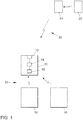
- Figure 1 shows a mobile device, here in this example in the form of a vehicle 10, such as a car, truck, motorcycle, bus or train. All land, air and water vehicles are regarded as vehicles here.
- the mobile device can also be a mobile computer, such as a tablet, or a mobile phone, such as a smartphone.
- the vehicle 10 contains a communication unit 12 which is in wireless or wired communication with a control unit 14 of the vehicle.
- the communication unit 12 is, for example, a transmitting / receiving unit for a V2X communication specified WLAN according to the IEEE 802.11p standard.
- the control device 14 can be a dedicated control device, for example for communication services or a car-to-X system.
- the control device can also be a computing unit such as a microprocessor.
- the vehicle 10 or the control device 14 includes a decentralized overload control 16, or a divider of a decentralized overload control.
- the decentralized overload control 16 is used to configure or control transmission properties of the communication unit 12.
- the communication unit 12 is used to establish a connection and / or communication between the vehicle 10 and further vehicles 18 which are identical or similar to the vehicle 10 in order to enable participation in a communication service 20.
- the other vehicles 18 contain one or more control units and a communication unit.
- the communication service 20 is, for example, a V2X or Vehicle-to-X service or a cellular service. Such services are referred to, for example, as car-to-car systems, car-to-infrastructure systems or car-to-X systems, where the X stands as a placeholder for any infrastructure facilities, other vehicles and other road users.
- Car2C Car2X
- C2C C2C or C2X systems
- V2V vehicle-to-vehicle systems
- V2I vehicle-to-infrastructure systems
- V2X vehicle-to-X systems
- the communication service 20 has at least one common transmission channel that is used or usable by all subscribers or vehicles.
- the communication service 20 is an ad-hoc network, that is to say a network without a central office Control in which the participants, such as vehicles 10 and 18, can log on and off at will.
- the communication service 20 is an ITS G5 network developed for car-to-X systems.
- the vehicles 18 communicate directly with the vehicle 10. It is also possible for other vehicles, such as the vehicle 22, to communicate indirectly via an installation 24, for example.
- the installation 24 can also be another stationary device, such as an infrastructure unit, for example a traffic light or a transmission mast, or another vehicle.
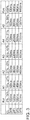
- the decentralized overload control 16 comprises a total of seven states, a relaxed state Rel, a first activated state A1, a second activated state A2, a third activated state A3, a fourth activated state A4, a fifth activated state A5 and a restricted state Res, whose classifications are based on a channel load CL in the transmission channel.
- the relaxed state Rel the decentralized overload control 16 is not active, there the channel load is very low.
- the activated states A1 to A5 the decentralized overload control 16 is active, since there is a sometimes considerable (here up to 59%) channel load CL.
- the restricted state Res the channel load CL is so great that normal operation is difficult to maintain.
- the first activated state A1 starts at 19% channel load.
- the 0 to less than 19% channel load selected here for the relaxed state Rel have proven to be well dimensioned for free operation and a smooth transition between the relaxed state Rel and the activated states.
- the second activated state A2 is defined for a channel load CL of greater than or equal to 27 percent to less than 35 percent
- the third activated state A3 is defined for a channel load of greater than or equal to 35 percent to less than 43 percent
- the fourth activated state A4 for a channel load of greater than or equal to 43 percent to less than 51 percent is defined
- the fifth activated state A5 for a channel load of greater than or equal to 51 Percent to less than 59 percent is defined and that the restricted state Res is defined for a channel load of greater than or equal to 59 percent.
- each subscriber or the communication unit 12 of the subscriber is put into a state of the decentralized overload control 16.
- a specific data transmission interval T OFF is specified for the subscriber, which defines how long the subscriber is not allowed to access the transmission channel.
- the data transmission interval T OFF for the relaxed state Rel is 60 ms, for the first activated state A1 100 ms, for the second activated state A2 180 ms, for the third activated state A3 260 ms, for the fourth activated state A4 340 ms, for the fifth activated state A5 420 ms and for the restricted state Res 460 ms.
- the graded selection of the data transmission interval T OFF sets a prioritization by which the repetition frequency of the access to the transmission channel by the subscriber is regulated.
- FIG 3 a further table of a decentralized overload control 16 is shown.
- the tables from the Figures 2 and 3 can for example in a memory of the participant, for example in a control device 14 of a vehicle 10 or a register of a microprocessor of a smartphone.
- each overload control profile DP0, DP1, DP2, DP3 being assigned a specific data transmission interval for each status Rel, A1-A5 and Res.
- An overload control profile can be assigned to a subscriber or a data or message type; this can be permanent or temporary.
- a second dimension or a second aspect for prioritization during transmission or access to the transmission channel is introduced via the profile.
- a minimum data transmission interval of 100 ms is assigned to the first overload control profile DP0 for each state.
- Subscribers or messages with this profile can access the transmission channel at maximum frequency regardless of the channel load CL.
- the second and third overload control profiles DP 1 and DP2 are assigned a data transmission interval of 100 ms for the relaxed state Rel, a data transmission interval of 140 ms for the first activated state A1 and a data transmission interval of 180 ms for the second activated state A2, for which A data transmission interval of 220 ms is assigned to the third activated state A3, a data transmission interval of 260 ms is assigned to the fourth activated state A4, a data transmission interval of 300 ms is assigned to the fifth activated state A5 and a data transmission interval of 340 ms is assigned to the restricted state Res.
- the fourth overload control profile DP3 is assigned a data transmission interval of 100 ms for the relaxed state Rel, a data transmission interval of 350 ms for the first activated state A1, a data transmission interval of 600 ms for the second activated state A2 and a data transmission interval of 600 ms for the third activated state A3 Assigned a data transmission interval of 850 ms, assigned a data transmission interval of 1100 ms for the fourth activated state A4, assigned a data transmission interval of 1350 ms for the fifth activated state A5 and assigned a data transmission interval of 1600 ms for the restricted state Res.
- signals for example to increase the brake pressure, are assigned to the overload control profile DP1.
- Such messages or signals can be viewed as Decentralized Environment Notification Messages (DENM) messages.
- DENM Decentralized Environment Notification Messages
- Position reports that contain information about the participant such as speed, direction and the like and can be sent cyclically, such as every 100 ms assigned to the overload control profile DP2. These messages can correspond to Cooperative Awareness Message (CAM) messages.
- CAM Cooperative Awareness Message
- the fourth overload control profile DP3 Messages from convenience functions, such as access to the Internet or a status message from a traffic light, are assigned to the fourth overload control profile DP3, for example. If, for example, the signal from a traffic light that it still has a red phase of a certain period, for example seven seconds, is delayed by 1 second by the decentralized overload control 16, the receiver can be set up to display the difference between the specified period and the delay to calculate. In this example, the receiving subscriber is informed that the red phase continues for six seconds.
- One or more, preferably not more than two, further overload control profiles can be provided in order, for example, to provide an open channel for further participants, such as a smartphone.
- further participants such as a smartphone.
- the communication system can also offer bandwidth for subscribers outside the system.
- the participants outside the system can be integrated via appropriate gateways or interfaces.
Landscapes
- Engineering & Computer Science (AREA)
- Computer Networks & Wireless Communication (AREA)
- Signal Processing (AREA)
- Mobile Radio Communication Systems (AREA)
Description
- Die Erfindung betrifft ein Verfahren und eine Vorrichtung zur Konfiguration einer Datenübertragung über einen Übertragungskanal eines drahtlosen Kommunikationssystems mit dezentraler Überlastregelung, sowie ein Fahrzeug und ein Computerprogrammprodukt.
- Die Steuerung von Datenverkehr oder Nachrichten ist Kommunikationsnetzwerken ein wichtiger Punkt, um die Zuverlässigkeit und Effizienz zu erhöhen oder zu gewährleiten. Auch bei C2C (Car-to-Car) Netzwerken ist dies ein wichtiger Punkt, da sicherheitsrelevante Informationen mit niedriger Latenz und hoher Zuverlässigkeit auch in Situationen mit hoher Fahrzeugdichte und/oder Geschwindigkeit übertragen werden müssen.
- Bei derzeitigen Ansätzen solcher Kommunikations- oder Kooperationsnetzwerke gelangt ein gemeinsam genutztes Übertragungsmedium, das heißt alle Teilnehmer oder Fahrzeuge nutzen den gleichen Übertragungskanal, in einem ad-hoc Netzwerk ohne zentrale Steuerung zum Einsatz. Deshalb wird oftmals eine dezentrale Überlastregelung DCC (Decentralised Congestion Control) vorgeschlagen. Aufgrund der hohen Mobilität der Teilnehmer muss die dezentrale Überlastregelung Situationen mit sich schnell ändernden Kanallasten verarbeiten können.
- ETSI TS 102 687 beschreibt Grundlagen der dezentralen Überlastregelung DCC mit vier Mechanismen, der Leistungssteuerung, der Übertragungsratensteuerung, der Empfindlichkeitssteuerung und der Datenratensteuerung. Die Unterteilung in entspannte, aktivierte und eingeschränkte Zustände wird beschrieben.
- ETSI TS 102 724 beschreibt Überlastregelungsprofile DP (DCC Profile).
-
DE 10 2012 208 645 A1 undDE 10 2013 205 058 A1 offenbaren ein Verfahren zum Betreiben einer stationären Einrichtung, bei der eine Adresszuordnung gemäß ermittelter geographischer Position erfolgt. -
DE 10 2013 013 621 A1 offenbart einen sicherheitskonformen Kanalwechsel in intelligenten Transportsystemen, wobei der Kanalwechsel in Abhängigkeit von einem Konfliktrisiko mit anderen Verkehrsteilnehmern vorgenommen wird. -
DE 10 2014 201 648 A1 offenbart ein Verfahren zur Kommunikation innerhalb eines nach Art des ad-hoc zusammenwirkenden, insbesondere Drahtlos-Kraftfahrzeugkommunikationssystems, bei dem eine Bestimmung der eigenen Position auf der aktuellen Fahrspur erfolgt. ETSI TR 101 612 V1.1.1 (2014-09) offenbart eine Leistungsprüfung von reaktiven und linear adaptiven DCC Mechanismen. Der reaktive Ansatz basiert beispielsweise auf einem entspannten, fünf aktiven und einem eingeschränkten DCC Zustand, wobei jeder aktive Zustand einer Einschränkung des nutzbaren Rtx im Kanal zugeordnet ist, und der linear adaptive Ansatz eine Zielvorgabe CL setzt und dann den Rtx positiv oder negativ anpasst, um die Zielvorgabe CL zu erreichen. - ETSI TR 101 613 V1 .1 .1 (2015-09) beschreibt eine Validierungsvorrichtung und Ergebnisse für eine schichtübergreifende DCC Management Einheit zum Betrieb in einem ITS G5A und ITS G5B Medium unter Einsatz eines entspannten, fünf aktiven und eines eingeschränkten DCC Zustands.
- Bansal, G. et al.; "Comparing LIMERIC and DCC Approaches for VANET Channel Congestion Control", in: IEEE Wireless Vehicular Communications (WiVeC) 2014, Seiten 1-7, September 2014, vergleicht LIMERIC und DCC Ansätze zur Kanalüberlastregelung in IEEE 802.11 p-basierten Fahrzeugen und ad-hoc Netzwerken.
- Der Erfindung liegt nun die Aufgabe zugrunde, den Datenverkehr eines drahtlosen Kommunikationssystems mit dezentraler Überlastregelung zu verbessern.
- Diese Aufgabe wird gelöst durch ein Verfahren gemäß Anspruch1, eine Vorrichtung gemäß Anspruch 10, ein Fahrzeug gemäß Anspruch 12 beziehungsweise ein Computerprogrammprodukt gemäß Anspruch 13.
- Das erfindungsgemäße Verfahren zur Konfiguration einer Datenübertragung über einen Übertragungskanal eines drahtlosen Kommunikationssystems mit dezentraler Überlastregelung, wobei die dezentrale Überlastregelung einen entspannten Zustand, einen eingeschränkten Zustand und fünf aktivierte Zustände umfasst, deren Einteilung auf einer Kanallast in dem Übertragungskanal basiert.
- Der Übertragungskanal kann einen oder mehrere physikalische Kanäle und/oder logische Kanäle, wie Kontroll- oder Servicekanäle, umfassen. Die Kanallast gibt die Last oder Beladung des Übertragungskanals durch Daten oder Nachrichten an und wird in Prozent angegeben. Der Prozentwert der Kanallast ist dann der belegte Anteil von der gesamten Bandbreite, die 100 Prozent entspricht, des Kanals.
- Das erfindungsgemäße Verfahren hat den Vorteil, dass die Leistungsfähigkeit insbesondere unter schwierigen Bedingungen hinsichtlich der Paketfehlerrate, von Paketkollisionen und der Paketübermittlungsverzögerung oder -latenz verbessert wird. Es hat sich gezeigt, dass die Vorgabe von fünf aktivierten Zuständen dazu führt, dass die Zustände nur relativ selten gewechselt werden, obwohl die Bandbreite jedes der fünf aktivierten Zustände schmaler ist als der üblicherweise nur eine vorgesehene aktivierte Zustand. Durch die geringere Anzahl an Wechseln, beziehungsweise der häufigere Verbleib der dezentralen Überlastregelung in einem der aktiven Zustände kann die Effizienz der Datenübertragung erhöht werden.
- Jeder der fünf aktivierten Zustände kann für eine Kanallast von sechs Prozent bis zehn Prozent, vorzugsweise acht Prozent, definiert werden. Diese Bandbreite hat sich während Tests als besonders vorteilhaft gezeigt.
- Vorteilhaft kann vorgesehen sein, dass der entspannte Zustand (Rel) für eine Kanallast von 0 Prozent bis kleiner 17 bis 21 Prozent definiert ist, dass ein erster aktivierter Zustand für eine Kanallast von 17 bis 21 Prozent bis kleiner 25 bis 29 Prozent definiert ist, dass ein zweiter aktivierter Zustand für eine Kanallast von 25 bis 29 Prozent bis kleiner 33 bis 37 Prozent definiert ist, dass ein dritter aktivierter Zustand für eine Kanallast von 33 bis 37 Prozent bis kleiner 41 bis 45 Prozent definiert ist, dass ein vierter aktivierter Zustand für eine Kanallast von 41 bis 45 Prozent bis kleiner 49 bis 53 Prozent definiert ist, dass ein fünfter aktivierter Zustand für eine Kanallast von 49 bis 53 Prozent bis kleiner 57 bis 61 Prozent definiert ist und dass der eingeschränkte Zustand für eine Kanallast von größer gleich 57 bis 61 Prozent definiert ist. Diese weitere Spezifikation aller Zustände erlaubt eine sehr gute Überlastregelung.
- Weiter kann vorteilhaft vorgesehen sein, dass der entspannte Zustand (Rel) für eine Kanallast von größer gleich 0 Prozent bis kleiner 19 Prozent definiert ist, dass ein erster aktivierter Zustand für eine Kanallast von größer gleich 19 Prozent bis kleiner 27 Prozent definiert ist, dass ein zweiter aktivierter Zustand für eine Kanallast von größer gleich 27 Prozent bis kleiner 35 Prozent definiert ist, dass ein dritter aktivierter Zustand für eine Kanallast von größer gleich 35 Prozent bis kleiner 43 Prozent definiert ist, dass ein vierter aktivierter Zustand für eine Kanallast von größer gleich 43 Prozent bis kleiner 51 Prozent definiert ist, dass ein fünfter aktivierter Zustand für eine Kanallast von größer gleich 51 Prozent bis kleiner 59 Prozent definiert ist und dass der eingeschränkte Zustand für eine Kanallast von größer gleich 59 Prozent definiert ist. Auch diese weitere Spezifikation aller Zustände erlaubt eine sehr gute Überlastregelung.
- Jedem der Zustände wird ein spezifisches Datenübertragungsintervall geordnet. Das Datenübertragungsintervall wird üblicherweise in Millisekunden (ms) bemessen und gibt den Zeitraum an, ab dem die nächste Nachricht oder die nächsten Daten über den Übertragungskanal geschickt werden dürfen. Anders ausgedrückt, gibt das Datenübertragungsintervall die Pause zwischen zwei Sendungen beziehungsweise zwischen zwei Zugriffen auf den Übertragungskanal an, in der der Teilnehmer nicht auf den Übertragungskanal zugreifen darf.
- Es kann vorgesehen sein, dass das Datenübertragungsintervall für den entspannten Zustand 40 bis 80, vorzugsweise 60 ms, für einen ersten aktivierten Zustand 80 bis 120, vorzugsweise 100 ms, für einen zweiten aktivierten Zustand 160 bis 200, vorzugsweise 180 ms, für einen dritten aktivierten Zustand 240 bis 280, vorzugsweise 260 ms, für einen vierten aktivierten Zustand 320 bis 360, vorzugsweise 340 ms, für einen fünften aktivierten Zustand 400 bis 440, vorzugsweise 420 ms und für den eingeschränkten Zustand 440 bis 480, vorzugsweise 460 ms beträgt. Es hat sich gezeigt, dass diese ansteigenden Datenübertragungsintervalle sehr gute Ergebnisse liefern.
- Vier Überlastregelungsprofile sind vorgesehen, wobei jedem Überlastregelungsprofil ein spezifisches Datenübertragungsintervall für jeden Zustand zugeordnet wird. Durch die Überlastregelungsprofile wird gewissermaßen eine zweite Dimension für die dezentrale Überlastregelung eingeführt, was die Effizienz und die Flexibilität erhöht. Neben den vier Überlastregelungsprofile kann ein fünftes Überlastregelungsprofil zum Durchleiten anderer Dienste wie zum Beispiel von einem Smartphone definiert werden. Durch die Überlastregelungsprofile können bestimmte Teilnehmer und/oder Dienste oder Typen von Daten oder Nachrichten priorisiert oder mit weniger Priorität behandelt werden.
- Einem ersten Überlastregelungsprofil wird für jeden Zustand dasselbe minimale spezifische Datenübertragungsintervall zugeordnet. Das minimale Datenübertragungsintervall wird dabei der minimal möglichen Latenz des Kommunikationssystems, also Sender, Übertragungsstrecke und/oder Empfänger, entsprechen. So steht ein Überlastregelungsprofil zur Verfügung, das eine besonders priorisierte Übertragung erlaubt, zum Beispiel für sehr relevante Informationen wie bei einem Unfallereignis.
- Es kann vorgesehen sein, dass einem ersten Überlastregelungsprofil für jeden Zustand ein Datenübertragungsintervall von 100 ms zugeordnet wird, dass einem zweiten und dritten Überlastregelungsprofil für den entspannten Zustand ein Datenübertragungsintervall von 100 ms zugeordnet wird, für einen ersten aktivierten Zustand ein Datenübertragungsintervall von 140 ms zugeordnet wird, für einen zweiten aktivierten Zustand ein Datenübertragungsintervall von 180 ms zugeordnet wird, für einen dritten aktivierten Zustand ein Datenübertragungsintervall von 220 ms zugeordnet wird, für einen vierten aktivierten Zustand ein Datenübertragungsintervall von 260 ms zugeordnet wird, für einen fünften aktivierten Zustand ein Datenübertragungsintervall von 300 ms zugeordnet wird und für den eingeschränkten Zustand ein Datenübertragungsintervall von 340 ms zugeordnet wird und dass einem vierten Überlastregelungsprofil für den entspannten Zustand ein Datenübertragungsintervall von 100 ms zugeordnet wird, für einen ersten aktivierten Zustand ein Datenübertragungsintervall von 350 ms zugeordnet wird, für einen zweiten aktivierten Zustand ein Datenübertragungsintervall von 600 ms zugeordnet wird, für einen dritten aktivierten Zustand ein Datenübertragungsintervall von 850 ms zugeordnet wird, für einen vierten aktivierten Zustand ein Datenübertragungsintervall von 1100 ms zugeordnet wird, für einen fünften aktivierten Zustand ein Datenübertragungsintervall von 1350 ms zugeordnet wird und für den eingeschränkten Zustand ein Datenübertragungsintervall von 1600 ms zugeordnet wird. Diese weitere Spezifikation aller Überlastregelungsprofile erlaubt eine sehr gute Überlastregelung.
- Über ein erstes und/oder zweites Überlastregelungsprofil können Decentralized Environment Notification Messages (DENM) Nachrichten gesendet werden und/oder über ein drittes Überlastregelungsprofil können Cooperative Awareness Message (CAM) Nachrichten gesendet werden. Gemäß dem Verfahren können unterschiedliche Nachrichtentypen des Fahrzeug-zu-X Netzwerks in Abhängigkeit von ihrer Wichtigkeit und/oder Dringlichkeit unterschiedlich behandelt und übertragen werden. Dies erlaubt eine Erhöhung von Effizienz und Sicherheit.
- Das drahtlose Kommunikationssystem kann ein ad-hoc Netzwerk für die Kommunikation von mobilen Geräten sein, insbesondere ein Netzwerk nach einem WLAN-Standard. Die beschriebene dezentrale Überlastregelung eignet sich für derartige Netzwerke besonders.
- Das drahtlose Kommunikationssystem kann ein ITS G5 Netzwerk sein. Das ITS (Intelligent Transportation System) G5 Netzwerk wird für diese Zwecke definiert und eignet sich daher besonders.
- Die erfindungsgemäße Vorrichtung zur Konfiguration einer Datenübertragung über einen Übertragungskanal eines drahtlosen Kommunikationssystems mit dezentraler Überlastregelung sieht vor, dass die Vorrichtung, insbesondere ein Steuergerät für ein Fahrzeug oder ein Mobilfunkgerät, eingerichtet ist, ein wie zuvor beschriebenes Verfahren durchzuführen. Insbesondere bei Fahrzeuge und Mobilfunkgeräten verspricht das Verfahren aufgrund der hohen Mobilität und/oder Geschwindigkeit der Teilnehmer besondere Vorteile bei der zuverlässigen Datenübertragung. Es gelten die gleichen Vorteile und Modifikationen wie zuvor beschrieben.
- Das erfindungsgemäße Fahrzeug umfasst eine Vorrichtung wie zuvor beschrieben. Es gelten die gleichen Vorteile und Modifikationen wie zuvor beschrieben.
- Das erfindungsgemäße Computer-Programmprodukt umfasst Programmcode zur Durchführung des zuvor beschriebenen Verfahrens, wenn das Programmprodukt auf einer Recheneinheit oder einer zuvor beschriebenen Vorrichtung ausgeführt wird. Es gelten die gleichen Vorteile und Modifikationen wie zuvor beschrieben.
- Weitere bevorzugte Ausgestaltungen der Erfindung ergeben sich aus den übrigen, in den Unteransprüchen genannten Merkmalen.
- Die verschiedenen in dieser Anmeldung genannten Ausführungsformen der Erfindung sind, sofern im Einzelfall nicht anders ausgeführt, mit Vorteil miteinander kombinierbar.
- Die Erfindung wird nachfolgend in Ausführungsbeispielen anhand der zugehörigen Zeichnungen erläutert. Es zeigen:
- Figur 1
- eine schematische Darstellung eines drahtlosen Kommunikationssystems mit dezentraler Überlastregelung;
- Figur 2
- eine Konfigurationstabelle einer dezentralen Überlastregelung; und
- Figur 3
- eine weitere Konfigurationstabelle einer dezentralen Überlastregelung.
-
Figur 1 zeigt ein Mobilgerät, hier in diesem Beispiel in Form eines Fahrzeugs 10, wie zum Beispiel einem PKW, LKW, Motorrad, Bus oder Bahn. Als Fahrzeug werden hier sämtliche Land-, Luft- und Wasserfahrzeuge angesehen. Das Mobilgerät kann auch ein mobiler Computer, wie zum Beispiel ein Tablet, oder ein Mobiltelefon, wie zum Beispiel ein Smartphone sein. - Das Fahrzeug 10 enthält eine Kommunikationseinheit 12, die in drahtloser oder drahtgebundener Kommunikation mit einem Steuergerät 14 des Fahrzeugs steht. Die Kommunikationseinheit 12 ist zum Beispiel eine Sende/Empfangseinheit für ein V2X-Kommunikation spezifiziertes WLAN gemäß dem IEEE 802.11p Standard.
- Das Steuergerät 14 kann ein dediziertes Steuergerät zum Beispiel für Kommunikationsdienste oder ein Car-to-X-System sein. Auch kann das Steuergerät eine Recheneinheit wie zum Beispiel ein Mikroprozessor sein. Des Weiteren umfasst das Fahrzeug 10 beziehungsweise das Steuergerät 14 eine dezentrale Überlastregelung 16, beziehungsweise einen Teiler einer dezentralen Überlastregelung. Die dezentrale Überlastregelung 16 dient dazu, Sendeeigenschaften der Kommunikationseinheit 12 zu konfigurieren beziehungsweise zu steuern.
- Die Kommunikationseinheit 12 dient zum Aufbau einer Verbindung und/oder der Kommunikation zwischen dem Fahrzeug 10 und weiteren Fahrzeugen 18, die identisch oder ähnlich zu dem Fahrzeug 10 sind, um so die Teilnahme an einem Kommunikationsdienst 20 zu ermöglichen. Die weiteren Fahrzeuge 18 enthalten ein oder mehrere Steuergeräte sowie eine Kommunikationseinheit. Der Kommunikationsdienst 20 ist zum Beispiel ein V2X oder Vehicle-to-X Dienst oder ein Mobilfunkdienst. Derartige Dienste werden zum Beispiel als Car-to-Car-Systeme, Car-to-Infrastructure-Systeme oder Car-to-X-Systeme bezeichnet, wobei das X als Platzhalter für beliebige Infrastruktureinrichtungen, andere Fahrzeuge und andere Verkehrsteilnehmer steht. Weitere übliche Bezeichnungen sind Car2C-, Car2X-, C2C- bzw. C2X-Systeme, Vehicle-to-Vehicle-Systeme (V2V), Vehicle-to-Infrastructure-Systeme (V2I) oder Vehicle-to-X-Systeme (V2X).
- Der Kommunikationsdienst 20 hat mindestens einen gemeinsam, das heißt von allen Teilnehmern beziehungsweise Fahrzeugen, genutzten oder nutzbaren Übertragungskanal. Der Kommunikationsdienst 20 ist ein ad-hoc Netzwerk, das heißt ein Netzwerk ohne zentrale Steuerung, bei dem sich die Teilnehmer, wie die Fahrzeuge 10 und 18, beliebig an- und abmelden können. Insbesondere ist der Kommunikationsdienst 20 ein für Car-to-X-Systeme entwickeltes ITS G5 Netzwerk.
- Die Fahrzeuge 18 kommunizieren direkt mit dem Fahrzeug 10. Ebenso ist es möglich das weitere Fahrzeuge, wie zum Beispiel das Fahrzeug 22, indirekt über zum Beispiel eine Installation 24 kommunizieren. Die Installation 24 kann auch eine andere stationäre Einrichtung, wie ein Infrastruktureinheit, zum Beispiel eine Ampel oder ein Sendemast, oder ein weiteres Fahrzeug sein.
- Anhand der
Figuren 2 und3 wird nun die Funktionsweise der dezentralen Überlastregelung 16 beschrieben, die zum Beispiel in dem Steuergerät 14 des Fahrzeugs 10 ausgeführt wird. - In
Figur 2 ist eine Konfigurationstabelle einer dezentralen Überlastregelung 16 dargestellt. Die dezentrale Überlastregelung 16 umfasst insgesamt sieben Zustände, einen entspannten Zustand Rel, einen ersten aktivierten Zustand A1, einen zweiten aktivierten Zustand A2, einen dritten aktivierten Zustand A3, einen vierten aktivierten Zustand A4, einen fünften aktivierten Zustand A5 und einen eingeschränkten Zustand Res umfasst, deren Einteilungen auf einer Kanallast CL in dem Übertragungskanal basieren. In dem entspannten Zustand Rel ist die dezentrale Überlastregelung 16 nicht aktiv, dort ist die Kanallast sehr niedrig. In den aktivierten Zuständen A1 bis A5 ist die dezentrale Überlastregelung 16 aktiv, da eine, teils erhebliche (hier bis zu 59%), Kanallast CL vorliegt. In dem eingeschränkten Zustand Res ist die Kanallast CL so groß, dass ein normaler Betrieb nur schwer aufrechtzuerhalten ist. - Es hat sich gezeigt, dass eine Kanallast oder ein anteiliger Wert von 8% der Bandbreite des Übertragungskanals beziehungsweise der Kanallast optimal für einen aktivierten Zustand A1 bis A5 ist. Der erste aktivierte Zustand A1 setzt bei 19 % Kanallast ein. Die hier gewählten 0 bis kleiner 19 % Kanallast für den entspannten Zustand Rel haben sich als gut dimensioniert für einen freien Betrieb und einen sanften Übergang zwischen dem entspannten Zustand Rel und den aktivierten Zuständen erwiesen.
- Weiter ist vorgesehen, dass der zweite aktivierte Zustand A2 für eine Kanallast CL von größer gleich 27 Prozent bis kleiner 35 Prozent definiert ist, dass der dritte aktivierte Zustand A3 für eine Kanallast von größer gleich 35 Prozent bis kleiner 43 Prozent definiert ist, dass der vierte aktivierte Zustand A4 für eine Kanallast von größer gleich 43 Prozent bis kleiner 51 Prozent definiert ist, dass der fünfte aktivierte Zustand A5 für eine Kanallast von größer gleich 51 Prozent bis kleiner 59 Prozent definiert ist und dass der eingeschränkte Zustand Res für eine Kanallast von größer gleich 59 Prozent definiert ist.
- Anhand der Kanallast CL, die entweder vom Teilnehmer gemessen oder diesem mitgeteilt wird, wird jeder Teilnehmer beziehungsweise die Kommunikationseinheit 12 des Teilnehmers in einen Zustand der dezentralen Überlastregelung 16 gesetzt.
- Mit der Zuordnung zu einem der Zustände der dezentralen Überlastregelung 16 wird für den Teilnehmer ein spezifisches Datenübertragungsintervall TOFF angegeben, das definiert wie lange der Teilnehmer nicht auf den Übertragungskanal zugreifen darf.
- Hier beträgt das Datenübertragungsintervall TOFF für den entspannten Zustand Rel 60 ms, für den ersten aktivierten Zustand A1 100 ms, für den zweiten aktivierten Zustand A2 180 ms, für den dritten aktivierten Zustand A3 260 ms, für den vierten aktivierten Zustand A4 340 ms, für den fünften aktivierten Zustand A5 420 ms und für den eingeschränkten Zustand Res 460 ms. Durch die abgestufte Wahl des Datenübertragungsintervalls TOFF wird eine Priorisierung eingestellt, durch welche die Wiederholfrequenz des Zugriffs auf den Übertragungskanal durch den Teilnehmer geregelt wird.
- In
Figur 3 ist eine weitere Tabelle einer dezentralen Überlastregelung 16 dargestellt. Die Tabellen aus denFiguren 2 und3 können zum Beispiel in einem Speicher des Teilnehmers, zum Beispiel in einem Steuergerät 14 eines Fahrzeugs 10 oder einem Register eines Mikroprozessors eines Smartphones. - Gemäß der Tabelle aus
Figur 3 sind zusätzlich zu den Zuständen der dezentralen Überlastregelung 16 noch vier Überlastregelungsprofile DP0, DP1, DP2, DP3 vorgesehen, wobei jedem Überlastregelungsprofil DP0, DP1, DP2, DP3 ein spezifisches Datenübertragungsintervall für jeden Zustand Rel, A1-A5 und Res zugeordnet ist. - Einem Teilnehmer oder einem Daten- oder Nachrichtentyp kann ein Überlastregelungsprofil zugeordnet werden, dies kann dauerhaft oder temporär geschehen. Über das Profil wird eine zweite Dimension beziehungsweise ein zweiter Aspekt für eine Priorisierung bei der Übertragung oder dem Zugriff auf den Übertragungskanal eingeführt.
- In diesem Beispiel wird dem ersten Überlastregelungsprofil DP0 für jeden Zustand ein minimales Datenübertragungsintervall von zum Beispiel 100 ms zugeordnet. Somit können Teilnehmer oder Nachrichten mit diesem Profil unabhängig von der Kanallast CL mit maximaler Frequenz auf den Übertragungskanal zugreifen.
- Dem zweiten und dritten Überlastregelungsprofil DP 1 und DP2 sind für den entspannten Zustand Rel ein Datenübertragungsintervall von 100 ms zugeordnet, für den ersten aktivierten Zustand A1 ein Datenübertragungsintervall von 140 ms zugeordnet, für den zweiten aktivierten Zustand A2 ein Datenübertragungsintervall von 180 ms zugeordnet, für den dritten aktivierten Zustand A3 ein Datenübertragungsintervall von 220 ms zugeordnet, für den vierten aktivierten Zustand A4 ein Datenübertragungsintervall von 260 ms zugeordnet, für den fünften aktivierten Zustand A5 ein Datenübertragungsintervall von 300 ms zugeordnet und für den eingeschränkten Zustand Res ein Datenübertragungsintervall von 340 ms zugeordnet.
- Dem vierten Überlastregelungsprofil DP3 ist für den entspannten Zustand Rel ein Datenübertragungsintervall von 100 ms zugeordnet, für den ersten aktivierten Zustand A1 ein Datenübertragungsintervall von 350 ms zugeordnet, für den zweiten aktivierten Zustand A2 ein Datenübertragungsintervall von 600 ms zugeordnet, für den dritten aktivierten Zustand A3 ein Datenübertragungsintervall von 850 ms zugeordnet, für den vierten aktivierten Zustand A4 ein Datenübertragungsintervall von 1100 ms zugeordnet, für den fünften aktivierten Zustand A5 ein Datenübertragungsintervall von 1350 ms zugeordnet und für den eingeschränkten Zustand Res ein Datenübertragungsintervall von 1600 ms zugeordnet.
- Mit dieser Ausgestaltung wird sichergestellt, das bei immer höherer Kanallast nur die wichtigsten Nachrichten oder Daten über den Übertragungskanal übertragen werden. In dem Beispiel einer Car-2-X Kommunikation werden zum Bespiel Nachrichten einen Crash betreffen, wie zum Beispiel Signale zur Parametrierung von Airbags oder Gurtstraffern, dem Überlastregelungsprofil DP0 zugeordnet.
- Zum Beispiel bei einer starken Bremsung, also in einer Situation, in der noch einige Sekunden Reaktionszeit verbleiben, werden Signale, zum Beispiel zur Erhöhung des Bremsdrucks, dem Überlastregelungsprofil DP1 zugeordnet.
- Derartige Nachrichten oder Signale können als Decentralized Environment Notification Messages (DENM) Nachrichten angesehen werden.
- Positionsmeldungen, die Informationen des Teilnehmers wie zum Beispiel Geschwindigkeit, Richtung und ähnliches enthalten und zyklisch, wie etwa alle 100 ms gesendet werden, können dem Überlastregelungsprofil DP2 zugeordnet werden. Diese Nachrichten können Cooperative Awareness Message (CAM) Nachrichten entsprechen.
- Dem vierten Überlastregelungsprofil DP3 sind zum Beispiel Nachrichten von Komfortfunktionen zugeordnet, wie zum Beispiel ein Zugriff auf das Internet oder eine Statusmeldung einer Ampel. Wenn zum Beispiel die Meldung einer Ampel, dass diese noch eine Rotphase von einem bestimmten Zeitraum, zum Beispiel von sieben Sekunden, hat, um 1 Sekunde durch die dezentrale Überlastregelung 16 verzögert wird, kann der Empfänger eingerichtet sein, die Differenz zwischen angegebenem Zeitraum und Verzögerung zu berechnen. In diesem Beispiel wird dem empfangenen Teilnehmer mitgeteilt, dass die Rotphase noch sechs Sekunden andauert.
- Ein oder mehrere, vorzugsweise nicht mehr als zwei, weitere Überlastregelungsprofile können vorgesehen sein, um zum Beispiel einen offenen Kanal für weitere Teilnehmer, wie zum Beispiel ein Smartphone, zur Verfügung zu stellen. Auf diese Weise kann das Kommunikationssystem, wenn nur wenig Bandbreite durch Systemdaten oder Systemnachrichten belegt ist, auch Bandbreite für systemexterne Teilnehmer anbieten. Die systemexternen Teilnehmer können über entsprechende Gateways oder Schnittstellen eingebunden werden.
-
- 10
- Fahrzeug
- 12
- Kommunikationseinheit
- 14
- Steuergerät
- 16
- dezentrale Überlastregelung
- 18
- Fahrzeug
- 20
- Kommunikationsdienst
- 22
- Fahrzeug
- 24
- Installation
- Rel
- entspannter Zustand
- A1
- erster aktivierter Zustand
- A2
- zweiter aktivierter Zustand
- A3
- dritter aktivierter Zustand
- A4
- vierter aktivierter Zustand
- A5
- fünfter aktivierter Zustand
- Res
- eingeschränkter Zustand
- CL
- Kanallast
- TOFF
- Datenübertragungsintervall
- DP0
- Überlastregelungsprofil
- DP1
- Überlastregelungsprofil
- DP2
- Überlastregelungsprofil
- DP3
- Überlastregelungsprofil
Claims (13)
- Verfahren zur Konfiguration einer Datenübertragung über einen Übertragungskanal eines drahtlosen Kommunikationssystems (20) mit dezentraler Überlastregelung (16), wobei die dezentrale Überlastregelung (16) einen entspannten Zustand (Rel) einen eingeschränkten Zustand (Res) und fünf aktivierte Zustände (A1, A2, A3, A4, A5) umfasst, und wobei die Einteilung aller Zustände auf einer Kanallast (CL) in dem Übertragungskanal basiert, dadurch gekennzeichnet, dass vier Überlastregelungsprofile (DP0, DP1, DP2, DP3) für eine Priorisierung bei der Datenübertragung oder einem Zugriff auf dem Übertragungskanal vorgesehen sind, wobei jedem Überlastregelungsprofil (DP0, DP1, DP2, DP3) ein spezifisches Datenübertragunsintervall (TOFF) für jeden Zustand zugeordnet wird, wobei das spezifische Datenübertragungsintervall die Pause zwischen zwei Sendungen beziehungsweise zwischen zwei Zugriffen auf den Übertragungskanal angibt, und wobei einem ersten Überlastregelungsprofil (DP0) für jeden Zustand dasselbe minimale spezifische Datenübertragunsintervall (TOFF) zugeordnet wird.
- Verfahren nach Anspruch 1, dadurch gekennzeichnet, dass jeder der fünf aktivierten Zustände (A1, A2, A3, A4, A5) für eine Kanallast (CL) von sechs Prozent bis zehn Prozent, vorzugsweise acht Prozent, definiert wird.
- Verfahren nach einem der vorhergehenden Ansprüche, dadurch gekennzeichnet, dass der entspannte Zustand (Rel) für eine Kanallast (CL) von 0 Prozent bis kleiner 17 bis 21 Prozent definiert ist, dass ein erster der fünf aktivierten Zustände (A1) für eine Kanallast (CL) von 17 bis 21 Prozent bis kleiner 25 bis 29 Prozent definiert ist, dass ein zweiter der fünf aktivierten Zustände (A2) für eine Kanallast (CL) von 25 bis 29 Prozent bis kleiner 33 bis 37 Prozent definiert ist, dass ein dritter der fünf aktivierten Zustände (A3) für eine Kanallast (CL) von 33 bis 37 Prozent bis kleiner 41 bis 45 Prozent definiert ist, dass ein vierter der fünf aktivierten Zustände (A4) für eine Kanallast (CL) von 41 bis 45 Prozent bis kleiner 49 bis 53 Prozent definiert ist, dass ein fünfter der fünf aktivierten Zustände (A5) für eine Kanallast (CL) von 49 bis 53 Prozent bis kleiner 57 bis 61 Prozent definiert ist und dass der eingeschränkte Zustand (Res) für eine Kanallast (CL) von größer gleich 57 bis 61 Prozent definiert ist.
- Verfahren nach den vorhergehenden Ansprüchen 1 und 2, dadurch gekennzeichnet, dass der entspannte Zustand (Rel) für eine Kanallast (CL) von größer gleich 0 Prozent bis kleiner 19 Prozent definiert ist, dass ein erster der fünf aktivierten Zustände (A1) für eine Kanallast (CL) von größer gleich 19 Prozent bis kleiner 27 Prozent definiert ist, dass ein zweiter der fünf aktivierten Zustände (A2) für eine Kanallast (CL) von größer gleich 27 Prozent bis kleiner 35 Prozent definiert ist, dass ein dritter der fünf aktivierten Zustände (A3) für eine Kanallast (CL) von größer gleich 35 Prozent bis kleiner 43 Prozent definiert ist, dass ein vierter der fünf aktivierten Zustände (A4) für eine Kanallast (CL) von größer gleich 43 Prozent bis kleiner 51 Prozent definiert ist, dass ein fünfter der fünf aktivierten Zustände (A5) für eine Kanallast (CL) von größer gleich 51 Prozent bis kleiner 59 Prozent definiert ist und dass der eingeschränkte Zustand (Res) für eine Kanallast (CL) von größer gleich 59 Prozent definiert ist.
- Verfahren nach Anspruch 1, dadurch gekennzeichnet, dass das spezifische Datenübertragungsintervall (TOFF) für den entspannten Zustand (Rel) 40 bis 80, vorzugsweise 60 ms, für einen ersten der fünf aktivierten Zustände (A1) 80 bis 120, vorzugsweise 100 ms, für einen zweiten der fünf aktivierten Zustände (A2) 160 bis 200, vorzugsweise 180 ms, für einen dritten der fünf aktivierten Zustände (A3) 240 bis 280, vorzugsweise 260 ms, für einen vierten der fünf aktivierten Zustände (A4) 320 bis 360, vorzugsweise 340 ms, für einen fünften der fünf aktivierten Zustände (A5) 400 bis 440, vorzugsweise 420 ms und für den eingeschränkten Zustand (Res) 440 bis 480, vorzugsweise 460 ms beträgt.
- Verfahren nach einem der vorhergehenden Ansprüche, dadurch gekennzeichnet, dass dem ersten Überlastregelungsprofil (DPO) der vier Überlastregelungsprofile für jeden Zustand (Rel, A1, A2, A3, A4, A5, Res) ein Datenübertragungsintervall (TOFF) von 100 ms zugeordnet wird, dass einem zweiten und dritten Überlastregelungsprofil (DP1, DP2) der vier Überlastregelungsprofile für den entspannten Zustand (Rel) ein Datenübertragungsintervall (TOFF) von 100 ms zugeordnet wird, für einen ersten aktivierten Zustand (A1) der fünf aktivierten Zustände ein Datenübertragungsintervall (TOFF) von 140 ms zugeordnet wird, für einen zweiten aktivierten Zustand (A2) der fünf aktivierten Zustände ein Datenübertragungsintervall (TOFF) von 180 ms zugeordnet wird, für einen dritten aktivierten Zustand (A3) der fünf aktivierten Zustände ein Datenübertragungsintervall (TOFF) von 220 ms zugeordnet wird, für einen vierten aktivierten Zustand (A4) der fünf aktivierten Zustände ein Datenübertragungsintervall (TOFF) von 260 ms zugeordnet wird, für einen fünften aktivierten Zustand (A5) der fünf aktivierten Zustände ein Datenübertragungsintervall (TOFF) von 300 ms zugeordnet wird und für den eingeschränkten Zustand (Res) ein Datenübertragungsintervall (TOFF) von 340 ms zugeordnet wird, und dass einem vierten Überlastregelungsprofil (DP3) der vier Überlastregelungsprofile für den entspannten Zustand (Rel) ein Datenübertragungsintervall (TOFF) von 100 ms zugeordnet wird, für einen ersten aktivierten Zustand (A1) der fünf aktivierten Zustände ein Datenübertragungsintervall (TOFF) von 350 ms zugeordnet wird, für einen zweiten aktivierten Zustand (A2) der fünf aktivierten Zustände ein Datenübertragungsintervall (TOFF) von 600 ms zugeordnet wird, für einen dritten aktivierten Zustand (A3) der fünf aktivierten Zustände ein Datenübertragungsintervall (TOFF) von 850 ms zugeordnet wird, für einen vierten aktivierten Zustand (A4) der fünf aktivierten Zustände ein Datenübertragungsintervall (TOFF) von 1100 ms zugeordnet wird, für einen fünften aktivierten Zustand (A5) der fünf aktivierten Zustände ein Datenübertragungsintervall (TOFF) von 1350 ms zugeordnet wird und für den eingeschränkten Zustand (Res) ein Datenübertragungsintervall (TOFF) von 1600 ms zugeordnet wird.
- Verfahren nach einem der vorhergehenden Ansprüche, dadurch gekennzeichnet, dass über das erste und/oder ein zweites Überlastregelungsprofil (DPO, DP1) der vier Übertragungsprofile Decentralized Environment Notification Messages (DENM) Nachrichten gesendet werden und/oder dass über ein drittes Übertragungsprofil (DP2) der vier Überlastregelungsprofile Cooperative Awareness Message (CAM) Nachrichten gesendet werden.
- Verfahren nach einem der vorhergehenden Ansprüche, dadurch gekennzeichnet, dass das drahtlose Kommunikationssystem (20) ein ad-hoc Netzwerk für die Kommunikation von mobilen Geräten ist.
- Verfahren nach einem der vorhergehenden Ansprüche, dadurch gekennzeichnet, dass das drahtlose Kommunikationssystem (20) ein ITS G5 Netzwerk ist oder ein ad-hoc Netzwerk für die Kommunikation von mobilen Geräten nach einem WLAN-Standard ist.
- Vorrichtung zur Konfiguration einer Datenübertragung über einen Übertragungskanal eines drahtlosen Kommunikationssystems (20) mit dezentraler Überlastregelung (16), dadurch gekennzeichnet, dass die Vorrichtung eingerichtet ist, ein Verfahren nach einem der Ansprüche 1 bis 9 durchzuführen.
- Vorrichtung nach Anspruch 10, dadurch gekennzeichnet, dass die Vorrichtung ein Steuergerät (14) für ein Fahrzeug (10) oder ein Mobilfunkgerät ist.
- Fahrzeug (10), umfassend eine Vorrichtung nach Anspruch 11 oder 11.
- Computer-Programmprodukt mit Programmcode zur Durchführung des Verfahrens nach einem der Ansprüche 1 bis 9, wenn das Programmprodukt auf einer Recheneinheit oder einer Vorrichtung gemäß Anspruch 10 oder 11 ausgeführt wird.
Applications Claiming Priority (2)
| Application Number | Priority Date | Filing Date | Title |
|---|---|---|---|
| DE102015219785.9A DE102015219785A1 (de) | 2015-10-13 | 2015-10-13 | Verfahren und Vorrichtung zur Konfiguration einer Datenübertragung über einen Übertragungskanal eines drahtlosen Kommunikationssystems mit dezentraler Überlastregelung |
| PCT/EP2016/071393 WO2017063801A1 (de) | 2015-10-13 | 2016-09-12 | Verfahren und vorrichtung zur konfiguration einer datenübertragung über einen übertragungskanal eines drahtlosen kommunikationssystems mit dezentraler überlastregelung |
Publications (2)
| Publication Number | Publication Date |
|---|---|
| EP3363232A1 EP3363232A1 (de) | 2018-08-22 |
| EP3363232B1 true EP3363232B1 (de) | 2021-05-05 |
Family
ID=56979528
Family Applications (1)
| Application Number | Title | Priority Date | Filing Date |
|---|---|---|---|
| EP16769901.6A Active EP3363232B1 (de) | 2015-10-13 | 2016-09-12 | Verfahren und vorrichtung zur konfiguration einer datenübertragung über einen übertragungskanal eines drahtlosen kommunikationssystems mit dezentraler überlastregelung |
Country Status (5)
| Country | Link |
|---|---|
| US (1) | US10616790B2 (de) |
| EP (1) | EP3363232B1 (de) |
| CN (1) | CN108141783B (de) |
| DE (1) | DE102015219785A1 (de) |
| WO (1) | WO2017063801A1 (de) |
Families Citing this family (6)
| Publication number | Priority date | Publication date | Assignee | Title |
|---|---|---|---|---|
| KR102096505B1 (ko) * | 2016-04-01 | 2020-04-02 | 엘지전자 주식회사 | 무선 통신 시스템에서 단말에 의해 수행되는 v2x 전송 자원 선택 방법 및 상기 방법을 이용하는 단말 |
| CN107171965B (zh) * | 2017-05-31 | 2019-10-18 | 华南理工大学 | 基于分布式拥塞控制策略的车联网跨层机会路由方法 |
| EP3879375B1 (de) * | 2017-06-23 | 2023-12-06 | Volkswagen Aktiengesellschaft | Vorrichtung, verfahren und computerprogramm für globale platooning-steuerung und platooning-system |
| JP7250472B2 (ja) * | 2018-10-18 | 2023-04-03 | Hapsモバイル株式会社 | 基地局装置、プログラム、制御装置及び制御方法 |
| KR102936555B1 (ko) | 2019-05-03 | 2026-03-06 | 삼성전자주식회사 | 차량의 주행을 보조하는 전자 장치 및 방법 |
| DE102022123608A1 (de) | 2022-09-15 | 2024-03-21 | ASFINAG Maut Service GmbH | Verfahren zum infrastrukturgestützten Assistieren eines Kraftfahrzeugs |
Family Cites Families (11)
| Publication number | Priority date | Publication date | Assignee | Title |
|---|---|---|---|---|
| CN101741433B (zh) * | 2008-11-18 | 2013-02-27 | 上海摩波彼克半导体有限公司 | 无线通信系统上行传输中基于功率控制的tfc选择方法 |
| DE102011077882A1 (de) * | 2011-06-21 | 2012-12-27 | Siemens Aktiengesellschaft | Mobiles Ad-hoc-Netzwerk |
| DE102012208645A1 (de) | 2012-05-23 | 2013-11-28 | Siemens Aktiengesellschaft | Verfahren zum Betreiben einer stationären Einrichtung sowie stationäre Einrichtung innerhalb eines Systems zur Kommunikation |
| US20140272971A1 (en) * | 2013-03-14 | 2014-09-18 | Health Diagnostic Laboratory, Inc. | Unheated extraction of genomic dna in an automated laboratory system |
| DE102013205057B3 (de) * | 2013-03-21 | 2014-08-28 | Siemens Aktiengesellschaft | Verfahren zum Betreiben einer stationären Einrichtung sowie stationäre Einrichtung innerhalb eines Systems zur Kommunikation |
| DE102013205058A1 (de) | 2013-03-21 | 2014-09-25 | Siemens Aktiengesellschaft | Verfahren zum Betreiben einer stationären Einrichtung sowie stationäre Einrichtung innerhalb eines Systems zur Kommunikation |
| DE102013013621A1 (de) | 2013-08-15 | 2015-02-19 | Bayerische Motoren Werke Aktiengesellschaft | Sicherheitskonformer Kanalwechsel in intelligenten Transportsvstemen |
| DE102014201648A1 (de) | 2014-01-30 | 2015-07-30 | Siemens Aktiengesellschaft | Verfahren zur Kommunikation innerhalb eines nach Art des ad-hoc zusammenwirkenden, insbesondere Drahtlos-, Kraftfahrzeugkommunikationssystems, Einrichtung der Verkehrsinfrastruktur sowie Verkehrsteilnehmereinrichtung |
| US9980193B2 (en) * | 2014-12-12 | 2018-05-22 | Telefonaktiebolaget Lm Ericsson (Publ) | Transport format for communications |
| WO2016138649A1 (zh) * | 2015-03-04 | 2016-09-09 | 华为技术有限公司 | 一种通信方法及相关设备 |
| EP3304971B1 (de) * | 2015-06-08 | 2018-12-12 | Nec Corporation | Verfahren für mehrfachkanaloperation in einem fahrzeugnetzwerk und fahrzeugnetzwerk |
-
2015
- 2015-10-13 DE DE102015219785.9A patent/DE102015219785A1/de not_active Withdrawn
-
2016
- 2016-09-12 EP EP16769901.6A patent/EP3363232B1/de active Active
- 2016-09-12 US US15/767,658 patent/US10616790B2/en active Active
- 2016-09-12 CN CN201680060157.0A patent/CN108141783B/zh active Active
- 2016-09-12 WO PCT/EP2016/071393 patent/WO2017063801A1/de not_active Ceased
Also Published As
| Publication number | Publication date |
|---|---|
| DE102015219785A1 (de) | 2017-04-13 |
| WO2017063801A1 (de) | 2017-04-20 |
| CN108141783B (zh) | 2021-10-26 |
| EP3363232A1 (de) | 2018-08-22 |
| CN108141783A (zh) | 2018-06-08 |
| US10616790B2 (en) | 2020-04-07 |
| US20180310200A1 (en) | 2018-10-25 |
Similar Documents
| Publication | Publication Date | Title |
|---|---|---|
| WO2017063801A1 (de) | Verfahren und vorrichtung zur konfiguration einer datenübertragung über einen übertragungskanal eines drahtlosen kommunikationssystems mit dezentraler überlastregelung | |
| DE102016105784B4 (de) | Verfahren und Vorrichtung eines dynamischen Wi-Fi-Multikanalwechsels basierend auf einem Datenverkehrskontext | |
| EP2684416B1 (de) | Funk-sende-/funk-empfangseinrichtung und verfahren zur kommunikation innerhalb eines nach art des ad-hoc zusammenwirkenden, insbesondere drahtlos-, kraftfahrzeugkommunikationssystems | |
| EP1678887A1 (de) | Verfahren, funkstation und computerprogrammprodukt zum zugriff auf funkressourcen in einem adhoc-funkkommunikationssystem | |
| EP3092829A1 (de) | Zentrale kommunikationseinheit eines kraftfahrzeuges | |
| EP3656165A1 (de) | VERFAHREN ZUM BETREIBEN EINER NETZWERKINFRASTRUKTURSEITIGEN NETZWERKEINHEIT, EINE NETZWERKINFRASTRUKTURSEITIGE NETZWERKEINHEIT, EIN VERFAHREN ZUM BETREIBEN EINER STRAßENSEITIGEN NETZWERKEINHEIT UND EINE STRAßENSEITIGE NETZWERKEINHEIT | |
| EP3656176B1 (de) | Verfahren zum betreiben einer strassenseitigen netzwerkeinheit und strassenseitige netzwerkeinheit | |
| WO2004019639A1 (de) | Verfahren zum betrieb eines funksystems sowie sendende station und funksystem | |
| EP3146795A1 (de) | Clusterhead-vorrichtung welche als gateway zwichen vehicular ad-hoc netzwerk und zellularem netzwerk fungiert | |
| EP3656163A1 (de) | VERFAHREN ZUM BETREIBEN EINER NETZWERKINFRASTRUKTURSEITIGEN NETZWERKEINHEIT, NETZWERKINFRASTRUKTURSEITIGE NETZWERKEINHEIT, VERFAHREN ZUM BETREIBEN EINER STRAßENSEITIGEN NETZWERKEINHEIT, STRAßENSEITIGE NETZWERKEINHEIT | |
| DE102004024647B4 (de) | Verfahren und Funkstation zur Regulierung von Zugriffsraten in einem Funkkommunikationssystem | |
| DE102013214946A1 (de) | Kommunikationsvorrichtung für ein Fahrzeug und System | |
| DE102006014308A1 (de) | Verfahren zur Multi-Hop-Datenübertragung in einem ad-hoc-Netz mit versteckten Knoten | |
| WO2005096552A1 (de) | Verfahren zur zuweisung von funkressourcen für ein wlan | |
| DE102009044757B4 (de) | Dienst-Übermittlungsverfahren und Dienst-Bereitstellungsvorrichtung | |
| EP1719291B1 (de) | Verfahren, Zwischenstation sowie zentrale Steuereinrichtung zur Paketvermittelten Datenübertragung in einem selbstorganisierten Funknetzwerk | |
| WO2020193019A1 (de) | Verfahren zum auswählen einer ersten übertragungstechnologie oder einer zweiten übertragungstechnologie in abhängigkeit einer anforderung eines aktuellen anwendungsfalls sowie elektronische recheneinrichtung | |
| DE10129740B4 (de) | Übertragungssystem für Interfahrzeug-Kommunikation | |
| DE102011105454B4 (de) | Verfahren zum Übertragen von Daten | |
| DE10044828C2 (de) | Verfahren zur Steuerung der Auslastung eines lokalen Netzes und Vorrichtung zur Durchführung des Verfahrens | |
| EP3656180B1 (de) | Erste strassenseitige netzwerkeinheit und verfahren zum betreiben der ersten strassenseitige netzwerkeinheit | |
| DE102007036875B4 (de) | Verfahren und Vorrichtung zur Datenübertragung in einem Funknetzwerk von oder zu einem Kraftfahrzeug | |
| DE102008026183A1 (de) | Verfahren und Kommunikationssystem zur Übertragung von Nachrichten | |
| WO2006134060A1 (de) | Verfahren und vorrichtung zur datenübertragung | |
| WO2005096562A1 (de) | Verfahren zur signalübertragung in einem funk-kommunikationssystem |
Legal Events
| Date | Code | Title | Description |
|---|---|---|---|
| STAA | Information on the status of an ep patent application or granted ep patent |
Free format text: STATUS: THE INTERNATIONAL PUBLICATION HAS BEEN MADE |
|
| PUAI | Public reference made under article 153(3) epc to a published international application that has entered the european phase |
Free format text: ORIGINAL CODE: 0009012 |
|
| STAA | Information on the status of an ep patent application or granted ep patent |
Free format text: STATUS: REQUEST FOR EXAMINATION WAS MADE |
|
| 17P | Request for examination filed |
Effective date: 20180514 |
|
| AK | Designated contracting states |
Kind code of ref document: A1 Designated state(s): AL AT BE BG CH CY CZ DE DK EE ES FI FR GB GR HR HU IE IS IT LI LT LU LV MC MK MT NL NO PL PT RO RS SE SI SK SM TR |
|
| AX | Request for extension of the european patent |
Extension state: BA ME |
|
| DAV | Request for validation of the european patent (deleted) | ||
| DAX | Request for extension of the european patent (deleted) | ||
| STAA | Information on the status of an ep patent application or granted ep patent |
Free format text: STATUS: EXAMINATION IS IN PROGRESS |
|
| 17Q | First examination report despatched |
Effective date: 20200415 |
|
| GRAP | Despatch of communication of intention to grant a patent |
Free format text: ORIGINAL CODE: EPIDOSNIGR1 |
|
| STAA | Information on the status of an ep patent application or granted ep patent |
Free format text: STATUS: GRANT OF PATENT IS INTENDED |
|
| INTG | Intention to grant announced |
Effective date: 20200819 |
|
| GRAJ | Information related to disapproval of communication of intention to grant by the applicant or resumption of examination proceedings by the epo deleted |
Free format text: ORIGINAL CODE: EPIDOSDIGR1 |
|
| STAA | Information on the status of an ep patent application or granted ep patent |
Free format text: STATUS: EXAMINATION IS IN PROGRESS |
|
| GRAP | Despatch of communication of intention to grant a patent |
Free format text: ORIGINAL CODE: EPIDOSNIGR1 |
|
| STAA | Information on the status of an ep patent application or granted ep patent |
Free format text: STATUS: GRANT OF PATENT IS INTENDED |
|
| INTC | Intention to grant announced (deleted) | ||
| INTG | Intention to grant announced |
Effective date: 20201209 |
|
| GRAS | Grant fee paid |
Free format text: ORIGINAL CODE: EPIDOSNIGR3 |
|
| GRAA | (expected) grant |
Free format text: ORIGINAL CODE: 0009210 |
|
| STAA | Information on the status of an ep patent application or granted ep patent |
Free format text: STATUS: THE PATENT HAS BEEN GRANTED |
|
| AK | Designated contracting states |
Kind code of ref document: B1 Designated state(s): AL AT BE BG CH CY CZ DE DK EE ES FI FR GB GR HR HU IE IS IT LI LT LU LV MC MK MT NL NO PL PT RO RS SE SI SK SM TR |
|
| REG | Reference to a national code |
Ref country code: GB Ref legal event code: FG4D Free format text: NOT ENGLISH |
|
| REG | Reference to a national code |
Ref country code: CH Ref legal event code: EP |
|
| REG | Reference to a national code |
Ref country code: AT Ref legal event code: REF Ref document number: 1391396 Country of ref document: AT Kind code of ref document: T Effective date: 20210515 |
|
| REG | Reference to a national code |
Ref country code: IE Ref legal event code: FG4D Free format text: LANGUAGE OF EP DOCUMENT: GERMAN |
|
| REG | Reference to a national code |
Ref country code: DE Ref legal event code: R096 Ref document number: 502016012999 Country of ref document: DE |
|
| REG | Reference to a national code |
Ref country code: SE Ref legal event code: TRGR |
|
| REG | Reference to a national code |
Ref country code: LT Ref legal event code: MG9D |
|
| PG25 | Lapsed in a contracting state [announced via postgrant information from national office to epo] |
Ref country code: FI Free format text: LAPSE BECAUSE OF FAILURE TO SUBMIT A TRANSLATION OF THE DESCRIPTION OR TO PAY THE FEE WITHIN THE PRESCRIBED TIME-LIMIT Effective date: 20210505 Ref country code: LT Free format text: LAPSE BECAUSE OF FAILURE TO SUBMIT A TRANSLATION OF THE DESCRIPTION OR TO PAY THE FEE WITHIN THE PRESCRIBED TIME-LIMIT Effective date: 20210505 Ref country code: BG Free format text: LAPSE BECAUSE OF FAILURE TO SUBMIT A TRANSLATION OF THE DESCRIPTION OR TO PAY THE FEE WITHIN THE PRESCRIBED TIME-LIMIT Effective date: 20210805 Ref country code: HR Free format text: LAPSE BECAUSE OF FAILURE TO SUBMIT A TRANSLATION OF THE DESCRIPTION OR TO PAY THE FEE WITHIN THE PRESCRIBED TIME-LIMIT Effective date: 20210505 |
|
| PG25 | Lapsed in a contracting state [announced via postgrant information from national office to epo] |
Ref country code: PL Free format text: LAPSE BECAUSE OF FAILURE TO SUBMIT A TRANSLATION OF THE DESCRIPTION OR TO PAY THE FEE WITHIN THE PRESCRIBED TIME-LIMIT Effective date: 20210505 Ref country code: NO Free format text: LAPSE BECAUSE OF FAILURE TO SUBMIT A TRANSLATION OF THE DESCRIPTION OR TO PAY THE FEE WITHIN THE PRESCRIBED TIME-LIMIT Effective date: 20210805 Ref country code: PT Free format text: LAPSE BECAUSE OF FAILURE TO SUBMIT A TRANSLATION OF THE DESCRIPTION OR TO PAY THE FEE WITHIN THE PRESCRIBED TIME-LIMIT Effective date: 20210906 Ref country code: RS Free format text: LAPSE BECAUSE OF FAILURE TO SUBMIT A TRANSLATION OF THE DESCRIPTION OR TO PAY THE FEE WITHIN THE PRESCRIBED TIME-LIMIT Effective date: 20210505 Ref country code: GR Free format text: LAPSE BECAUSE OF FAILURE TO SUBMIT A TRANSLATION OF THE DESCRIPTION OR TO PAY THE FEE WITHIN THE PRESCRIBED TIME-LIMIT Effective date: 20210806 Ref country code: IS Free format text: LAPSE BECAUSE OF FAILURE TO SUBMIT A TRANSLATION OF THE DESCRIPTION OR TO PAY THE FEE WITHIN THE PRESCRIBED TIME-LIMIT Effective date: 20210905 Ref country code: LV Free format text: LAPSE BECAUSE OF FAILURE TO SUBMIT A TRANSLATION OF THE DESCRIPTION OR TO PAY THE FEE WITHIN THE PRESCRIBED TIME-LIMIT Effective date: 20210505 |
|
| REG | Reference to a national code |
Ref country code: NL Ref legal event code: MP Effective date: 20210505 |
|
| PG25 | Lapsed in a contracting state [announced via postgrant information from national office to epo] |
Ref country code: NL Free format text: LAPSE BECAUSE OF FAILURE TO SUBMIT A TRANSLATION OF THE DESCRIPTION OR TO PAY THE FEE WITHIN THE PRESCRIBED TIME-LIMIT Effective date: 20210505 |
|
| PG25 | Lapsed in a contracting state [announced via postgrant information from national office to epo] |
Ref country code: SK Free format text: LAPSE BECAUSE OF FAILURE TO SUBMIT A TRANSLATION OF THE DESCRIPTION OR TO PAY THE FEE WITHIN THE PRESCRIBED TIME-LIMIT Effective date: 20210505 Ref country code: SM Free format text: LAPSE BECAUSE OF FAILURE TO SUBMIT A TRANSLATION OF THE DESCRIPTION OR TO PAY THE FEE WITHIN THE PRESCRIBED TIME-LIMIT Effective date: 20210505 Ref country code: CZ Free format text: LAPSE BECAUSE OF FAILURE TO SUBMIT A TRANSLATION OF THE DESCRIPTION OR TO PAY THE FEE WITHIN THE PRESCRIBED TIME-LIMIT Effective date: 20210505 Ref country code: DK Free format text: LAPSE BECAUSE OF FAILURE TO SUBMIT A TRANSLATION OF THE DESCRIPTION OR TO PAY THE FEE WITHIN THE PRESCRIBED TIME-LIMIT Effective date: 20210505 Ref country code: EE Free format text: LAPSE BECAUSE OF FAILURE TO SUBMIT A TRANSLATION OF THE DESCRIPTION OR TO PAY THE FEE WITHIN THE PRESCRIBED TIME-LIMIT Effective date: 20210505 Ref country code: ES Free format text: LAPSE BECAUSE OF FAILURE TO SUBMIT A TRANSLATION OF THE DESCRIPTION OR TO PAY THE FEE WITHIN THE PRESCRIBED TIME-LIMIT Effective date: 20210505 Ref country code: RO Free format text: LAPSE BECAUSE OF FAILURE TO SUBMIT A TRANSLATION OF THE DESCRIPTION OR TO PAY THE FEE WITHIN THE PRESCRIBED TIME-LIMIT Effective date: 20210505 |
|
| REG | Reference to a national code |
Ref country code: DE Ref legal event code: R097 Ref document number: 502016012999 Country of ref document: DE |
|
| PLBE | No opposition filed within time limit |
Free format text: ORIGINAL CODE: 0009261 |
|
| STAA | Information on the status of an ep patent application or granted ep patent |
Free format text: STATUS: NO OPPOSITION FILED WITHIN TIME LIMIT |
|
| 26N | No opposition filed |
Effective date: 20220208 |
|
| REG | Reference to a national code |
Ref country code: CH Ref legal event code: PL |
|
| REG | Reference to a national code |
Ref country code: BE Ref legal event code: MM Effective date: 20210930 |
|
| PG25 | Lapsed in a contracting state [announced via postgrant information from national office to epo] |
Ref country code: IS Free format text: LAPSE BECAUSE OF FAILURE TO SUBMIT A TRANSLATION OF THE DESCRIPTION OR TO PAY THE FEE WITHIN THE PRESCRIBED TIME-LIMIT Effective date: 20210905 Ref country code: MC Free format text: LAPSE BECAUSE OF FAILURE TO SUBMIT A TRANSLATION OF THE DESCRIPTION OR TO PAY THE FEE WITHIN THE PRESCRIBED TIME-LIMIT Effective date: 20210505 Ref country code: AL Free format text: LAPSE BECAUSE OF FAILURE TO SUBMIT A TRANSLATION OF THE DESCRIPTION OR TO PAY THE FEE WITHIN THE PRESCRIBED TIME-LIMIT Effective date: 20210505 |
|
| PG25 | Lapsed in a contracting state [announced via postgrant information from national office to epo] |
Ref country code: LU Free format text: LAPSE BECAUSE OF NON-PAYMENT OF DUE FEES Effective date: 20210912 Ref country code: IT Free format text: LAPSE BECAUSE OF FAILURE TO SUBMIT A TRANSLATION OF THE DESCRIPTION OR TO PAY THE FEE WITHIN THE PRESCRIBED TIME-LIMIT Effective date: 20210505 Ref country code: IE Free format text: LAPSE BECAUSE OF NON-PAYMENT OF DUE FEES Effective date: 20210912 Ref country code: BE Free format text: LAPSE BECAUSE OF NON-PAYMENT OF DUE FEES Effective date: 20210930 |
|
| PG25 | Lapsed in a contracting state [announced via postgrant information from national office to epo] |
Ref country code: LI Free format text: LAPSE BECAUSE OF NON-PAYMENT OF DUE FEES Effective date: 20210930 Ref country code: CH Free format text: LAPSE BECAUSE OF NON-PAYMENT OF DUE FEES Effective date: 20210930 |
|
| REG | Reference to a national code |
Ref country code: AT Ref legal event code: MM01 Ref document number: 1391396 Country of ref document: AT Kind code of ref document: T Effective date: 20210912 |
|
| PG25 | Lapsed in a contracting state [announced via postgrant information from national office to epo] |
Ref country code: AT Free format text: LAPSE BECAUSE OF NON-PAYMENT OF DUE FEES Effective date: 20210912 |
|
| P01 | Opt-out of the competence of the unified patent court (upc) registered |
Effective date: 20230523 |
|
| PG25 | Lapsed in a contracting state [announced via postgrant information from national office to epo] |
Ref country code: CY Free format text: LAPSE BECAUSE OF FAILURE TO SUBMIT A TRANSLATION OF THE DESCRIPTION OR TO PAY THE FEE WITHIN THE PRESCRIBED TIME-LIMIT Effective date: 20210505 |
|
| PG25 | Lapsed in a contracting state [announced via postgrant information from national office to epo] |
Ref country code: HU Free format text: LAPSE BECAUSE OF FAILURE TO SUBMIT A TRANSLATION OF THE DESCRIPTION OR TO PAY THE FEE WITHIN THE PRESCRIBED TIME-LIMIT; INVALID AB INITIO Effective date: 20160912 |
|
| PG25 | Lapsed in a contracting state [announced via postgrant information from national office to epo] |
Ref country code: MK Free format text: LAPSE BECAUSE OF FAILURE TO SUBMIT A TRANSLATION OF THE DESCRIPTION OR TO PAY THE FEE WITHIN THE PRESCRIBED TIME-LIMIT Effective date: 20210505 |
|
| PG25 | Lapsed in a contracting state [announced via postgrant information from national office to epo] |
Ref country code: TR Free format text: LAPSE BECAUSE OF FAILURE TO SUBMIT A TRANSLATION OF THE DESCRIPTION OR TO PAY THE FEE WITHIN THE PRESCRIBED TIME-LIMIT Effective date: 20210505 |
|
| PG25 | Lapsed in a contracting state [announced via postgrant information from national office to epo] |
Ref country code: MT Free format text: LAPSE BECAUSE OF FAILURE TO SUBMIT A TRANSLATION OF THE DESCRIPTION OR TO PAY THE FEE WITHIN THE PRESCRIBED TIME-LIMIT Effective date: 20210505 |
|
| PGFP | Annual fee paid to national office [announced via postgrant information from national office to epo] |
Ref country code: DE Payment date: 20250930 Year of fee payment: 10 |
|
| PGFP | Annual fee paid to national office [announced via postgrant information from national office to epo] |
Ref country code: GB Payment date: 20250923 Year of fee payment: 10 |
|
| PGFP | Annual fee paid to national office [announced via postgrant information from national office to epo] |
Ref country code: FR Payment date: 20250925 Year of fee payment: 10 |
|
| PGFP | Annual fee paid to national office [announced via postgrant information from national office to epo] |
Ref country code: SE Payment date: 20250924 Year of fee payment: 10 |