EP3361806B1 - Verfahren und vorrichtungen zur steuerung von kanalübertragung in einem drahtloskommunikationssystem - Google Patents
Verfahren und vorrichtungen zur steuerung von kanalübertragung in einem drahtloskommunikationssystem Download PDFInfo
- Publication number
- EP3361806B1 EP3361806B1 EP18151139.5A EP18151139A EP3361806B1 EP 3361806 B1 EP3361806 B1 EP 3361806B1 EP 18151139 A EP18151139 A EP 18151139A EP 3361806 B1 EP3361806 B1 EP 3361806B1
- Authority
- EP
- European Patent Office
- Prior art keywords
- pdcch
- slot
- symbol
- minimum function
- configuration
- Prior art date
- Legal status (The legal status is an assumption and is not a legal conclusion. Google has not performed a legal analysis and makes no representation as to the accuracy of the status listed.)
- Active
Links
Images


Classifications
-
- H—ELECTRICITY
- H04—ELECTRIC COMMUNICATION TECHNIQUE
- H04W—WIRELESS COMMUNICATION NETWORKS
- H04W72/00—Local resource management
- H04W72/20—Control channels or signalling for resource management
- H04W72/23—Control channels or signalling for resource management in the downlink direction of a wireless link, i.e. towards a terminal
- H04W72/231—Control channels or signalling for resource management in the downlink direction of a wireless link, i.e. towards a terminal the control data signalling from the layers above the physical layer, e.g. RRC or MAC-CE signalling
-
- H—ELECTRICITY
- H04—ELECTRIC COMMUNICATION TECHNIQUE
- H04L—TRANSMISSION OF DIGITAL INFORMATION, e.g. TELEGRAPHIC COMMUNICATION
- H04L5/00—Arrangements affording multiple use of the transmission path
- H04L5/003—Arrangements for allocating sub-channels of the transmission path
- H04L5/0053—Allocation of signalling, i.e. of overhead other than pilot signals
-
- H—ELECTRICITY
- H04—ELECTRIC COMMUNICATION TECHNIQUE
- H04L—TRANSMISSION OF DIGITAL INFORMATION, e.g. TELEGRAPHIC COMMUNICATION
- H04L5/00—Arrangements affording multiple use of the transmission path
- H04L5/0091—Signalling for the administration of the divided path, e.g. signalling of configuration information
- H04L5/0094—Indication of how sub-channels of the path are allocated
-
- H—ELECTRICITY
- H04—ELECTRIC COMMUNICATION TECHNIQUE
- H04W—WIRELESS COMMUNICATION NETWORKS
- H04W72/00—Local resource management
- H04W72/04—Wireless resource allocation
- H04W72/044—Wireless resource allocation based on the type of the allocated resource
- H04W72/0446—Resources in time domain, e.g. slots or frames
-
- H—ELECTRICITY
- H04—ELECTRIC COMMUNICATION TECHNIQUE
- H04W—WIRELESS COMMUNICATION NETWORKS
- H04W76/00—Connection management
- H04W76/20—Manipulation of established connections
- H04W76/27—Transitions between radio resource control [RRC] states
-
- H—ELECTRICITY
- H04—ELECTRIC COMMUNICATION TECHNIQUE
- H04B—TRANSMISSION
- H04B7/00—Radio transmission systems, i.e. using radiation field
- H04B7/24—Radio transmission systems, i.e. using radiation field for communication between two or more posts
- H04B7/26—Radio transmission systems, i.e. using radiation field for communication between two or more posts at least one of which is mobile
- H04B7/2603—Arrangements for wireless physical layer control
-
- H—ELECTRICITY
- H04—ELECTRIC COMMUNICATION TECHNIQUE
- H04L—TRANSMISSION OF DIGITAL INFORMATION, e.g. TELEGRAPHIC COMMUNICATION
- H04L5/00—Arrangements affording multiple use of the transmission path
- H04L5/0001—Arrangements for dividing the transmission path
- H04L5/0003—Two-dimensional division
- H04L5/0005—Time-frequency
- H04L5/0007—Time-frequency the frequencies being orthogonal, e.g. OFDM(A) or DMT
- H04L5/0008—Wavelet-division
-
- H—ELECTRICITY
- H04—ELECTRIC COMMUNICATION TECHNIQUE
- H04L—TRANSMISSION OF DIGITAL INFORMATION, e.g. TELEGRAPHIC COMMUNICATION
- H04L5/00—Arrangements affording multiple use of the transmission path
- H04L5/0001—Arrangements for dividing the transmission path
- H04L5/0014—Three-dimensional division
- H04L5/0023—Time-frequency-space
-
- H—ELECTRICITY
- H04—ELECTRIC COMMUNICATION TECHNIQUE
- H04L—TRANSMISSION OF DIGITAL INFORMATION, e.g. TELEGRAPHIC COMMUNICATION
- H04L5/00—Arrangements affording multiple use of the transmission path
- H04L5/003—Arrangements for allocating sub-channels of the transmission path
- H04L5/0053—Allocation of signalling, i.e. of overhead other than pilot signals
- H04L5/0055—Physical resource allocation for ACK/NACK
-
- H—ELECTRICITY
- H04—ELECTRIC COMMUNICATION TECHNIQUE
- H04W—WIRELESS COMMUNICATION NETWORKS
- H04W72/00—Local resource management
- H04W72/20—Control channels or signalling for resource management
- H04W72/23—Control channels or signalling for resource management in the downlink direction of a wireless link, i.e. towards a terminal
-
- H—ELECTRICITY
- H04—ELECTRIC COMMUNICATION TECHNIQUE
- H04W—WIRELESS COMMUNICATION NETWORKS
- H04W88/00—Devices specially adapted for wireless communication networks, e.g. terminals, base stations or access point devices
- H04W88/02—Terminal devices
-
- H—ELECTRICITY
- H04—ELECTRIC COMMUNICATION TECHNIQUE
- H04W—WIRELESS COMMUNICATION NETWORKS
- H04W88/00—Devices specially adapted for wireless communication networks, e.g. terminals, base stations or access point devices
- H04W88/08—Access point devices
Definitions
- This disclosure generally relates to wireless communication networks, and more particularly, to a method and apparatus for control channel transmission in a wireless communication system.
- IP Internet Protocol
- An exemplary network structure is an Evolved Universal Terrestrial Radio Access Network (E-UTRAN).
- E-UTRAN Evolved Universal Terrestrial Radio Access Network
- the E-UTRAN system can provide high data throughput in order to realize the above-noted voice over IP and multimedia services.
- a new radio technology for the next generation e.g., 5G
- 5G next generation
- changes to the current body of 3GPP standard are currently being submitted and considered to evolve and finalize the 3GPP standard.
- WO2016/143968A1 discloses methods for reducing control channel resource usage in short Transmission Time Intervals (sTTIs) by configuring time section transmission resource structures via RRC signaling in wireless communication systems.
- a method and apparatus are disclosed from the perspective of a UE (User Equipment) and a base station and apparatus are defined in the independent claims.
- the dependent claims define preferred embodiments thereof.
- Wireless communication systems are widely deployed to provide various types of communication such as voice, data, and so on. These systems may be based on code division multiple access (CDMA), time division multiple access (TDMA), orthogonal frequency division multiple access (OFDMA), 3GPP LTE (Long Term Evolution) wireless access, 3GPP LTE-A or LTE-Advanced (Long Term Evolution Advanced), 3GPP2 UMB (Ultra Mobile Broadband), WiMax, or some other modulation techniques.
- CDMA code division multiple access
- TDMA time division multiple access
- OFDMA orthogonal frequency division multiple access
- 3GPP LTE Long Term Evolution
- 3GPP LTE-A or LTE-Advanced Long Term Evolution Advanced
- 3GPP2 UMB Ultra Mobile Broadband
- WiMax Worldwide Interoperability for Mobile communications
- the exemplary wireless communication systems devices described below may be designed to support one or more standards such as the standard offered by a consortium named "3rd Generation Partnership Project” referred to herein as 3GPP, including: RP-150465, "New SI proposal: Study on Latency reduction techniques for LTE", Ericsson, Huawei ; TR 36.211 V13.1.0, “E-UTRA Study on latency reduction techniques for LTE (Release 13) "; TS 36.331, V13.2.0, “Evolved Universal Terrestrial Radio Access (E-UTRA); Radio Resource Control (RRC); Protocol specification (Release 13) "; TS 36.212 v13.1.0, “Evolved Universal Terrestrial Radio Access (E-UTRA); Multiplexing and channel coding (Release 13) "; TS 36.213 v13.1.1, “E-UTRA Physical layer procedures (Release 13) "; RAN1# 86bis Chairman's note; and RAN1#87 Chairman's note.
- 3GPP 3rd Generation
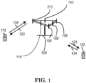
- Access terminal (AT) 122 is in communication with antennas 106 and 108, where antennas 106 and 108 transmit information to access terminal (AT) 122 over forward link 126 and receive information from access terminal (AT) 122 over reverse link 124.
- communication links 118, 120, 124 and 126 may use different frequency for communication.
- forward link 120 may use a different frequency then that used by reverse link 118.
- antenna groups each are designed to communicate to access terminals in a sector of the areas covered by access network 100.
- the transmitting antennas of access network 100 may utilize beamforming in order to improve the signal-to-noise ratio of forward links for the different access terminals 116 and 122. Also, an access network using beamforming to transmit to access terminals scattered randomly through its coverage causes less interference to access terminals in neighboring cells than an access network transmitting through a single antenna to all its access terminals.
- An access network may be a fixed station or base station used for communicating with the terminals and may also be referred to as an access point, a Node B, a base station, an enhanced base station, an evolved Node B (eNB), or some other terminology.
- An access terminal may also be called user equipment (UE), a wireless communication device, terminal, access terminal or some other terminology.
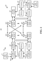
- FIG. 2 is a simplified block diagram of an embodiment of a transmitter system 210 (also known as the access network) and a receiver system 250 (also known as access terminal (AT) or user equipment (UE)) in a MIMO system 200.
- a transmitter system 210 also known as the access network
- a receiver system 250 also known as access terminal (AT) or user equipment (UE)
- traffic data for a number of data streams is provided from a data source 212 to a transmit (TX) data processor 214.
- TX transmit
- each data stream is transmitted over a respective transmit antenna.
- TX data processor 214 formats, codes, and interleaves the traffic data for each data stream based on a particular coding scheme selected for that data stream to provide coded data.
- the coded data for each data stream may be multiplexed with pilot data using OFDM techniques.
- the pilot data is typically a known data pattern that is processed in a known manner and may be used at the receiver system to estimate the channel response.
- the multiplexed pilot and coded data for each data stream is then modulated (i.e., symbol mapped) based on a particular modulation scheme (e.g., BPSK, QPSK, M-PSK, or M-QAM) selected for that data stream to provide modulation symbols.
- a particular modulation scheme e.g., BPSK, QPSK, M-PSK, or M-QAM
- the data rate, coding, and modulation for each data stream may be determined by instructions performed by processor 230.
- TX MIMO processor 220 may further process the modulation symbols (e.g., for OFDM).
- TX MIMO processor 220 then provides N T modulation symbol streams to N T transmitters (TMTR) 222a through 222t.
- TMTR TX MIMO processor 220 applies beamforming weights to the symbols of the data streams and to the antenna from which the symbol is being transmitted.
- Each transmitter 222 receives and processes a respective symbol stream to provide one or more analog signals, and further conditions (e.g., amplifies, filters, and upconverts) the analog signals to provide a modulated signal suitable for transmission over the MIMO channel.
- N T modulated signals from transmitters 222a through 222t are then transmitted from N T antennas 224a through 224t, respectively.
- the transmitted modulated signals are received by N R antennas 252a through 252r and the received signal from each antenna 252 is provided to a respective receiver (RCVR) 254a through 254r.
- Each receiver 254 conditions (e.g., filters, amplifies, and downconverts) a respective received signal, digitizes the conditioned signal to provide samples, and further processes the samples to provide a corresponding "received" symbol stream.
- An RX data processor 260 then receives and processes the N R received symbol streams from N R receivers 254 based on a particular receiver processing technique to provide N T "detected" symbol streams.
- the RX data processor 260 then demodulates, deinterleaves, and decodes each detected symbol stream to recover the traffic data for the data stream.
- the processing by RX data processor 260 is complementary to that performed by TX MIMO processor 220 and TX data processor 214 at transmitter system 210.
- a processor 270 periodically determines which pre-coding matrix to use (discussed below). Processor 270 formulates a reverse link message comprising a matrix index portion and a rank value portion.
- the reverse link message may comprise various types of information regarding the communication link and/or the received data stream.
- the reverse link message is then processed by a TX data processor 238, which also receives traffic data for a number of data streams from a data source 236, modulated by a modulator 280, conditioned by transmitters 254a through 254r, and transmitted back to transmitter system 210.
- the modulated signals from receiver system 250 are received by antennas 224, conditioned by receivers 222, demodulated by a demodulator 240, and processed by a RX data processor 242 to extract the reserve link message transmitted by the receiver system 250.
- Processor 230 determines which pre-coding matrix to use for determining the beamforming weights then processes the extracted message.
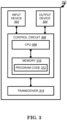
- FIG. 3 shows an alternative simplified functional block diagram of a communication device according to one embodiment of the invention.
- the communication device 300 in a wireless communication system can be utilized for realizing the UEs (or ATs) 116 and 122 in FIG. 1 or the base station (or AN) 100 in FIG. 1 , and the wireless communications system is preferably the LTE system.
- the communication device 300 may include an input device 302, an output device 304, a control circuit 306, a central processing unit (CPU) 308, a memory 310, a program code 312, and a transceiver 314.
- the control circuit 306 executes the program code 312 in the memory 310 through the CPU 308, thereby controlling an operation of the communications device 300.
- the communications device 300 can receive signals input by a user through the input device 302, such as a keyboard or keypad, and can output images and sounds through the output device 304, such as a monitor or speakers.
- the transceiver 314 is used to receive and transmit wireless signals, delivering received signals to the control circuit 306, and outputting signals generated by the control circuit 306 wirelessly.
- the communication device 300 in a wireless communication system can also be utilized for realizing the AN 100 in FIG. 1 .
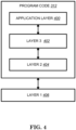
- FIG. 4 is a simplified block diagram of the program code 312 shown in FIG. 3 in accordance with one embodiment of the invention.
- the program code 312 includes an application layer 400, a Layer 3 portion 402, and a Layer 2 portion 404, and is coupled to a Layer 1 portion 406.
- the Layer 3 portion 402 generally performs radio resource control.
- the Layer 2 portion 404 generally performs link control.
- the Layer 1 portion 406 generally performs physical connections.
- Packet data latency is generally one of the important metrics for performance evaluation. Reducing packet data latency improves the system performance. In 3GPP RP-150465, the study item "study on latency reduction techniques for LTE" aims to investigate and standardize some techniques of latency reduction.
- Reducing latency of protocol is an important improvement between different generations or releases, which can improve efficiency as well as meeting new application requirements, e.g., real-time service.
- An effective method frequently adopted to reduce latency is to reduce the length of TTIs, from 10 ms in 3G to 1 ms in LTE.
- SI or WI was proposed to reduce the TTI to sub-ms level, e.g. 0.1 ⁇ 0.5 ms, by reducing the number of OFDM (Orthogonal Frequency Division Multiplexing) symbols within a TTI, without changing any existing LTE numerology, i.e., in LTE there is only one numerology.
- transmission in each downlink subframe shall use the same cyclic prefix length as used for downlink subframe #0.
- a downlink physical channel corresponds to a set of resource elements carrying information originating from higher layers and is the interface defined between 3GPP TS 36.212 [3] and the present document 3GPP TS 36.211.
- the following downlink physical channels are defined:
- a physical resource block is defined as N symb DL consecutive OFDM symbols in the time domain and N sc RB consecutive subcarriers in the frequency domain, where N symb DL and N sc RB are given by Table 6.2.3-1.
- a physical resource block thus consists of N symb DL ⁇ N sc RB resource elements, corresponding to one slot in the time domain and 180 kHz in the frequency domain.
- Physical resource blocks are numbered from 0 to N RB DL ⁇ 1 in the frequency domain.
- the UE may assume the PCFICH is transmitted when the number of OFDM symbols for PDCCH is greater than zero unless stated otherwise in [4, clause 12].
- CCE number n corresponds to bits b (72 n ), b (72 n + 1),..., b (72 n +71).
- the block of scrambled bits b ⁇ (0),..., b ⁇ ( M tot -1) shall be modulated as described in clause 7.1, resulting in a block of complex-valued modulation symbols d (0),..., d ( M symb -1).
- Table 6.8.3-1 specifies the modulation mappings applicable for the physical downlink control channel.
- Table 6.12-1 lists the value of N CP, l that shall be used. Note that different OFDM symbols within a slot in some cases have different cyclic prefix lengths.
- Cyclic prefix (CP) of the cell e.g., normal CP or extended CP
- duplex mode of the cell e.g., FDD or TDD
- MIB master information block
- PBCH physical broadcast channel
- SFN system frame number
- the UE would receive the DL control channel (e.g., PDCCH (Physical Downlink Control Channel) on proper resource elements and with proper payload size according to the system bandwidth and can acquire some more system information required to access the cell in system information block (SIB), such as whether the cell can be access, UL bandwidth and frequency, random access parameter, and so on.
- SIB system information block
- the UE then can perform random access and request the connection to the cell.
- the UE After the connection set up is complete, the UE would enter connected mode and be able to perform data transmission to the cell or perform data reception from the cell.
- the resource allocation for data reception and transmission is done according to system bandwidth (e.g., N RB DL or N RB UL in the following quotation) signaled in MIB or SIB. More details can be found in 3GPP TR 36.211, TS 36.331, TS 36.212, and TS 36.213 as follows:
- FIG.3.3-1 shows the processing structure for one DCI. The following coding steps can be identified:
- Each field is mapped in the order in which it appears in the description, including the zero-padding bit(s), if any, with the first field mapped to the lowest order information bit a 0 and each successive field mapped to higher order information bits.
- the most significant bit of each field is mapped to the lowest order information bit for that field, e.g. the most significant bit of the first field is mapped to a 0 .
- DCI format 0 is used for the scheduling of PUSCH in one UL cell.
- the UE shall apply the procedures described in this clause for both MCG and SCG
- a non-BL/CE UE For a non-BL/CE UE, and for FDD and transmission mode 1, there shall be 8 uplink HARQ processes per serving cell for non-subframe bundling operation, i.e. normal HARQ operation, and 3 uplink HARQ processes for subframe bundling operation when parameter e-HARQ-Pattern-r12 is set to TRUE and 4 uplink HARQ processes for subframe bundling operation otherwise.
- a non-BL/CE UE and for FDD and transmission mode 2
- the subframe bundling operation is configured by the parameter ttiBundling provided by higher layers.
- the subframe bundling operation is only applied to UL-SCH, such that four consecutive uplink subframes are used.
- a BL/CE UE is not expected to be configured with simultaneous PUSCH and PUCCH transmission.
- the UE shall upon detection on a given serving cell of a PDCCH/EPDCCH with DCI format 0/4 and/or a PHICH transmission in subframe n intended for the UE, adjust the corresponding PUSCH transmission in subframe n+4 according to the PDCCH/EPDCCH and PHICH information.
- the UE shall upon detection of a PDCCH/EPDCCH with DCI format 0/4 and/or a PHICH transmission in subframe n intended for the UE, adjust the corresponding PUSCH transmission for serving cell c in subframe n+4 according to the PDCCH/EPDCCH and PHICH information.
- the UE For normal HARQ operation, if the UE detects a PHICH transmission and if the most recent PUSCH transmission for the same transport block was using spatial multiplexing according to subclause 8.0.2 and the UE does not detect a PDCCH/EPDCCH with DCI format 4 in subframe n intended for the UE, the UE shall adjust the corresponding PUSCH retransmission in the associated subframe according to the PHICH information, and using the number of transmission layers and precoding matrix according to the most recent PDCCH/EPDCCH, if the number of negatively acknowledged transport blocks is equal to the number of transport blocks indicated in the most recent PDCCH/EPDCCH associated with the corresponding PUSCH.
- the UE For normal HARQ operation, if the UE detects a PHICH transmission and if the most recent PUSCH transmission for the same transport block was using spatial multiplexing according to subclause 8.0.2 and the UE does not detect a PDCCH/EPDCCH with DCI format 4 in subframe n intended for the UE, and if the number of negatively acknowledged transport blocks is not equal to the number of transport blocks indicated in the most recent PDCCH/EPDCCH associated with the corresponding PUSCH then the UE shall adjust the corresponding PUSCH retransmission in the associated subframe according to the PHICH information, using the precoding matrix with codebook index 0 and the number of transmission layers equal to number of layers corresponding to the negatively acknowledged transport block from the most recent PDCCH/EPDCCH.
- the UL DMRS resources are calculated according to the cyclic shift field for DMRS [3] in the most recent PDCCH/EPDCCH with DCI format 4 associated with the corresponding PUSCH transmission and number of layers corresponding to the negatively acknowledged transport block.
- the UE shall use the carrier indicator field value from the detected PDCCH/EPDCCH with uplink DCI format to determine the serving cell for the corresponding PUSCH transmission.
- a PDCCH/EPDCCH with CSI request field set to trigger an aperiodic CSI report is detected by a UE on subframe n, then on subframe n+4 UCI is mapped on the corresponding PUSCH transmission, when simultaneous PUSCH and PUCCH transmission is not configured for the UE.
- the UE When a UE is configured with higher layer parameter ttiBundling and configured with higher layer parameter e-HARQ-Pattern-r12 set to FALSE or not configured, for FDD and subframe bundling operation, the UE shall upon detection of a PDCCH/EPDCCH with DCI format 0 in subframe n intended for the UE, and/or a PHICH transmission in subframe n -5 intended for the UE, adjust the corresponding first PUSCH transmission in the bundle in subframe n +4 according to the PDCCH/EPDCCH and PHICH information.
- the UE shall upon detection of a PDCCH/EPDCCH with DCI format 0 in subframe n intended for the UE, and/or a PHICH transmission in subframe n -1 intended for the UE, adjust the corresponding first PUSCH transmission in the bundle in subframe n +4 according to the PDCCH/EPDCCH and PHICH information.
- the NDI as signalled on PDCCH/EPDCCH, the RV as determined in subclause 8.6.1, and the TBS as determined in subclause 8.6.2, shall be delivered to higher layers.
- the number of HARQ processes per serving cell shall be determined by the UL/DL configuration (Table 4.2-2 of [3]), as indicated in Table 8-1.
- the number of HARQ processes per serving cell for non-subframe bundling operation shall be twice the number determined by the UL/DL configuration (Table 4.2-2 of [3]) as indicated in Table 8-1 and there are two HARQ processes associated with a given subframe as described in [8].
- the maximum number of HARQ processes per serving cell shall be determined by the UL/DL configuration (Table 4.2-2 of [3]) according to the normal HARQ operation in Table 8-1.
- a BL/CE UE configured with CEModeB is not expected to support more than 2 uplink HARQ processes per serving cell.
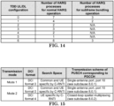
- a UE is semi-statically configured via higher layer signalling to transmit PUSCH transmissions signalled via PDCCH/EPDCCH according to one of two uplink transmission modes, denoted mode 1 - 2.
- a UE If a UE is configured by higher layers to decode PDCCHs with the CRC scrambled by the C-RNTI, the UE shall decode the PDCCH according to the combination defined in Table 8-3 and transmit the corresponding PUSCH.
- the scrambling initialization of this PUSCH corresponding to these PDCCHs and the PUSCH retransmission for the same transport block is by C-RNTI.
- a UE If a UE is configured by higher layers to decode EPDCCHs with the CRC scrambled by the C-RNTI, the UE shall decode the EPDCCH according to the combination defined in Table 8-3A and transmit the corresponding PUSCH.
- the scrambling initialization of this PUSCH corresponding to these EPDCCHs and the PUSCH retransmission for the same transport block is by C-RNTI.
- a UE If a UE is configured by higher layers to decode MPDCCHs with the CRC scrambled by the C-RNTI, the UE shall decode the MPDCCH according to the combination defined in Table 8-3B and transmit the corresponding PUSCH.
- the scrambling initialization of this PUSCH corresponding to these MPDCCHs and the PUSCH retransmission for the same transport block is by C-RNTI.
- Transmission mode 1 is the default uplink transmission mode for a UE until the UE is assigned an uplink transmission mode by higher layer signalling.
- a UE configured in transmission mode 2 When a UE configured in transmission mode 2 receives a DCI Format 0 uplink scheduling grant, it shall assume that the PUSCH transmission is associated with transport block 1 and that transport block 2 is disabled.
- a UE is configured by higher layers to decode PDCCHs with the CRC scrambled by the C-RNTI and is also configured to receive random access procedures initiated by "PDCCH orders", the UE shall decode the PDCCH according to the combination defined in Table 8-4.
- a UE is configured by higher layers to decode EPDCCHs with the CRC scrambled by the C-RNTI and is also configured to receive random access procedures initiated by "PDCCH orders", the UE shall decode the EPDCCH according to the combination defined in Table 8-4A.
- a UE is configured by higher layers to decode MPDCCHs with the CRC scrambled by the C-RNTI and is also configured to receive random access procedures initiated by "PDCCH orders", the UE shall decode the MPDCCH according to the combination defined in Table 8-4B.
- the UE shall decode the PDCCH according to the combination defined in Table 8-5 and transmit the corresponding PUSCH.
- the scrambling initialization of this PUSCH corresponding to these PDCCHs and PUSCH retransmission for the same transport block is by SPS C-RNTI.
- the scrambling initialization of initial transmission of this PUSCH without a corresponding PDCCH and the PUSCH retransmission for the same transport block is by SPS C-RNTI.
- the UE shall decode the EPDCCH according to the combination defined in Table 8-5A and transmit the corresponding PUSCH.
- the scrambling initialization of this PUSCH corresponding to these EPDCCHs and PUSCH retransmission for the same transport block is by SPS C-RNTI.
- the scrambling initialization of initial transmission of this PUSCH without a corresponding EPDCCH and the PUSCH retransmission for the same transport block is by SPS C-RNTI.
- the UE shall decode the MPDCCH according to the combination defined in Table 8-5B and transmit the corresponding PUSCH.
- the scrambling initialization of this PUSCH corresponding to these MPDCCHs and PUSCH retransmission for the same transport block is by SPS C-RNTI.
- the scrambling initialization of initial transmission of this PUSCH without a corresponding MPDCCH and the PUSCH retransmission for the same transport block is by SPS C-RNTI.
- a UE If a UE is configured by higher layers to decode PDCCHs with the CRC scrambled by the Temporary C-RNTI regardless of whether UE is configured or not configured to decode PDCCHs with the CRC scrambled by the C-RNTI, the UE shall decode the PDCCH according to the combination defined in Table 8-6 and transmit the corresponding PUSCH.
- the scrambling initialization of PUSCH corresponding to these PDCCH is by Temporary C-RNTI.
- Type 0 and Type 1 Two resource allocation schemes Type 0 and Type 1 are supported for PDCCH/EPDCCH with uplink DCI format.
- Resource allocation scheme Type 0 or Type 2 are supported for MPDCCH with uplink DCI format.
- resource allocation type bit is not present in the uplink DCI format, only resource allocation type 0 is supported.
- the selected resource allocation type for a decoded PDCCH/EPDCCH is indicated by a resource allocation type bit where type 0 is indicated by 0 value and type 1 is indicated otherwise.
- the UE shall interpret the resource allocation field depending on the resource allocation type bit in the PDCCH/EPDCCH with uplink DCI format detected.
- the resource allocation information for uplink resource allocation type 0 indicates to a scheduled UE a set of contiguously allocated virtual resource block indices denoted by n VRB .
- a resource allocation field in the scheduling grant consists of a resource indication value ( RIV ) corresponding to a starting resource block ( RB START ) and a length in terms of contiguously allocated resource blocks ( L CRBs ⁇ 1).
- RIV resource indication value
- the resource indication value is defined by
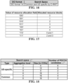
- the resource allocation information for uplink resource allocation type 1 indicates to a scheduled UE two sets of resource blocks with each set including one or more consecutive resource block groups of size P as given in table 7.1.6.1-1 assuming N RB UL as the system bandwidth.
- a combinatorial index r consists of log 2 N RB UL / P + 1 4 bits. The bits from the resource allocation field in the scheduling grant represent r unless the number of bits in the resource allocation field in the scheduling grant is
- Uplink resource allocation type 2 is only applicable for BL/CE UE configured with CEModeB.
- the resource allocation information for uplink resource allocation type 2 indicates to a scheduled UE a set of contiguously allocated resource blocks within a narrowband as given in Table 8.1.3-1
- the control region of each serving cell consists of a set of CCEs, numbered from 0 to N CCE, k -1 according to subclause 6.8.1 in [3], where N CCE, k is the total number of CCEs in the control region of subframe k .
- the UE shall monitor a set of PDCCH candidates on one or more activated serving cells as configured by higher layer signalling for control information, where monitoring implies attempting to decode each of the PDCCHs in the set according to all the monitored DCI formats.
- a BL/CE UE is not required to monitor PDCCH.
- the set of PDCCH candidates to monitor are defined in terms of search spaces, where a search space S k L at aggregation level L ⁇ ⁇ 1,2,4,8 ⁇ is defined by a set of PDCCH candidates.
- m' m.
- the carrier indicator field value corresponds to cif-InSchedulingCell-r13, otherwise, the carrier indicator field value is the same as ServCellIndex given in [11].
- the UE shall monitor one common search space in every non-DRX subframe at each of the aggregation levels 4 and 8 on the primary cell.
- a UE shall monitor common search space on a cell to decode the PDCCHs necessary to receive MBMS on that cell when configured by higher layers.
- a UE is not configured for EPDCCH monitoring, and if the UE is not configured with a carrier indicator field, then the UE shall monitor one PDCCH UE-specific search space at each of the aggregation levels 1, 2, 4, 8 on each activated serving cell in every non-DRX subframe.
- a UE is not configured for EPDCCH monitoring, and if the UE is configured with a carrier indicator field, then the UE shall monitor one or more UE-specific search spaces at each of the aggregation levels 1, 2, 4, 8 on one or more activated serving cells as configured by higher layer signalling in every non-DRX subframe.
- a UE is configured for EPDCCH monitoring on a serving cell, and if that serving cell is activated, and if the UE is not configured with a carrier indicator field, then the UE shall monitor one PDCCH UE-specific search space at each of the aggregation levels 1, 2, 4, 8 on that serving cell in all non-DRX subframes where EPDCCH is not monitored on that serving cell.
- a UE is configured for EPDCCH monitoring on a serving cell, and if that serving cell is activated, and if the UE is configured with a carrier indicator field, then the UE shall monitor one or more PDCCH UE-specific search spaces at each of the aggregation levels 1, 2, 4, 8 on that serving cell as configured by higher layer signalling in all non-DRX subframes where EPDCCH is not monitored on that serving cell.
- the common and PDCCH UE-specific search spaces on the primary cell may overlap.
- a UE configured with the carrier indicator field associated with monitoring PDCCH on serving cell c shall monitor PDCCH configured with carrier indicator field and with CRC scrambled by C-RNTI in the PDCCH UE specific search space of serving cell c .
- a UE configured with the carrier indicator field associated with monitoring PDCCH on the primary cell shall monitor PDCCH configured with carrier indicator field and with CRC scrambled by SPS C-RNTI in the PDCCH UE specific search space of the primary cell.
- the UE shall monitor the common search space for PDCCH without carrier indicator field.
- the UE For the serving cell on which PDCCH is monitored, if the UE is not configured with a carrier indicator field, it shall monitor the PDCCH UE specific search space for PDCCH without carrier indicator field, if the UE is configured with a carrier indicator field it shall monitor the PDCCH UE specific search space for PDCCH with carrier indicator field.
- the UE is not configured with a LAA Scell, the UE is not expected to monitor the PDCCH of a secondary cell if it is configured to monitor PDCCH with carrier indicator field corresponding to that secondary cell in another serving cell.
- the UE is not expected to monitor the PDCCH UE specific space of the LAA SCell if it is configured to monitor PDCCH with carrier indicator field corresponding to that LAA Scell in another serving cell,
- the UE shall monitor PDCCH candidates at least for the same serving cell.
- a UE configured to monitor PDCCH candidates with CRC scrambled by C-RNTI or SPS C-RNTI with a common payload size and with the same first CCE index n CCE (as described in subclause 10.1) but with different sets of DCI information fields as defined in [4] in the
- a serving cell is a LAA Scell
- the higher layer parameter subframeStartPosition for the Scell indicates 's07'
- the UE may receive PDCCH with DCI CRC scrambled by CC-RNTI as described in subclause 13A on the LAA Scell.
- the DCI formats that the UE shall monitor depend on the configured transmission mode per each serving cell as defined in subclause 7.1.
- a UE is configured with higher layer parameter skipMonitoringDCI-format0-1A for a serving cell, the UE is not required to monitor the PDCCH with DCI Format 0/1A in the UE specific search space for that serving cell.
- M L round a ⁇ M full L , where the value of a is determined according to Table 9.1.1-2 and M full L is determined according to Table 9.1.1-1 by replacing M ( L ) with M full L .
- Y k A ⁇ Y k ⁇ 1 mod D
- n RNTI The RNTI value used for n RNTI is defined in subclause 7.1 in downlink and subclause 8 in uplink.
- subcarrier spacing selection e.g., FFT size, definition/number of PRB, the design of CP, supportable system bandwidth, .... While as NR considers larger system bandwidth, and larger coherence bandwidth, inclusion of a larger sub carrier spacing is a nature choice.
- URLLC Ultra-Reliable and Low Latency Communication
- eMBB Enhanced Mobile Broadband
- the transmission interval/scheduling interval would need to be short.
- One way to shorten the transmission interval/scheduling interval is to increase the subcarrier spacing so as to reduce the OFDM symbol length in the time domain. For example, when subcarrier spacing is 15 KHz, 7 OFDM symbols transmission interval would occupy 0.5 ms while when subcarrier spacing is 60 KHz, 7OFDDM symbols transmission interval would occupy 0.125 ms, which can fulfil the stringent timing requirement easier.
- eMBB service might also use a reduced transmission interval while not necessarily always to do so as it would come with some potential side effect, e.g., larger control signaling overhead per amount of data traffic, shorter or more frequent control channel reception interval (may increase power consumption), shorter processing time (more complexity). Therefore, it is expected the communication system would be operated with different transmission intervals for different services or UEs. And multiplexing different transmission time interval within a system would be a challenge.
- RAN1 #86bis Chairman's Note and RAN1 #87 Chairman's Note describe how to define transmission interval as scheduling unit, such as slot or min-slot (shortened version of slot) with y is the number of OFDM symbol within a slot, as follows:
- control channel in NR (e.g., NR-PDCCH) needs to be designed for adapting different services requirements/scenarios.
- the composition of a slot may also be different, e.g., which portion of a slot would be DL or which portion of a slot would be uplink could depends on traffic property.
- pure downlink slot, pure uplink slot, or a slot with DL portion and uplink portion could be a minimum set of slot structure to be considered. It is further considered to use a group common control channel to indicate slot structure as follows:
- group common PDCCH and how to reveal the slot structure information is unclear.
- One key factor is how to group the UE.
- One example of grouping is to group UE with similar service requirements (e.g., the same numerology, the same RTT or timing relationship), or the same length of data duration (e.g., the same length of mini-slot). If the property of UE grouped together is more similar, the slot structure is more regular and the information amount related to slot structure could be less.
- the number of mini-slot with in a slot could be known by dividing the slot length with a mini-slot length, so as to allow UE realize which symbol is DL or UL or which symbol is control or data. Taking 2 symbol mini slots as an example. If the number of symbol can be used to carry mini slot is 12 and UE is indicated a mini-slot length of 2 symbols, the UE knows that symbols 0, 2, 4, 6, 8, and 10 may contain control information which requires PDCCH monitoring, while 1, 3, 5, 7, 9, and 11 do not contain control information which does not require PDCCH monitoring. Note that in the example, mini slots include the symbol for control information, while even if mini slot does not include control channel, similar situation can be observed.
- Another example is the number of DL symbol or UL symbol. For example, if all UEs in a group has a same ratio of DL symbol and UL symbol (e.g., after every 3 DL symbols there is one UL symbol), the UE may know that symbols 1, 2, 3, 5, 6, 7, 9, 10, and 11 are downlink symbols and symbols 4, 8, and 12 are uplink symbols, if a ratio (or the total number of symbols as well) are indicated in the group common PDCCH for the UEs. (Note that potential gap symbols are not considered in the above example, while similar situation can be observed if gap symbol exist.). The above example can be considered as "regular" slot structure.
- the slot structure is not regular (e.g., some UE(s) may use 2 symbol mini slots while some other UE(s) may use 5 symbol mini-slots), more detailed information is required for UE to know which symbol is control/data, and which symbol is UL/DL comparing with knowing the structure with one or a few factor(s) for regular structure case.
- a worst case could be using a bitmap for indicating the slot structure revealing the role (DL or UL control, or data) of each symbol which could be a quite significant overhead.
- a first concept of this invention is, in general, the UEs can be indicated with two modes to realize the slot structure.
- One mode leads to regular slot structure where the slot structure comprises several minimum function blocks.
- the minimum function blocks are identical from at least from the UE side in a same slot. Identical from UE side means every X symbol UE would expect a symbol with a same functionality (e.g., UL or DL control or data).
- group common PDCCH may indicate the value of X, and/or information to allow UE deriving X, and/or information to allow UE the functionality of each symbol within minimum function blocks (symbol 1 ⁇ symbol X).
- Another mode leads to allowing irregular slot structure where the slot structure can be known on a per symbol basis, e.g., using a bit map to indicate the functionality of each symbol where a least one bit corresponding to one symbol within a slot.
- a second concept is generally a base station groups UE(s) with different properties in a group common PDCCH while different UEs expect a regular structure with different minimum function blocks.
- the UEs receiving group common PDCCH may interpret or determines the slot structure with different minimum function blocks according to some pre-configurations.
- the difference of deriving the slot configuration may suffer from some constraint.
- One example of the difference is a length of the minimum function block of a first UE is an integer multiple of a length of the minimum function block of a second UE.
- the first UE may expect every 2*X symbol there is a symbol with a same functionality.
- the second UE may expect every X symbol there is a symbol with a same functionality.
- a first UE expects the first symbol of every X symbol containing control information (e.g., not other symbols) and a second UE expects the first two symbols of every X symbol containing control information (e.g., not other symbols).
- a UE is informed/configured a mode for determine a slot structure according to a group common PDCCH by a base station.
- a mode for determine a slot structure according to a group common PDCCH by a base station.
- the functionality comprises all or some or combinations of DL, UL, data, control symbol.
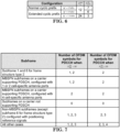
- the base station could indicate the length of minimum function block in a group common PDCCH.
- the functionality could comprise all or some or combinations of DL, UL, data, control symbol.
- the base station would indicate the length of minimum function block in a pre-configuration or RRC (Radio Resource Control) message.
- the base station could indicate the functionalities of each symbol within a minimum function block in a group common PDCCH.
- the base station indicates the functionalities of each symbol within a minimum function block in a RRC message.
- the base station could also indicate the functionalities of each symbol with a minimum function block in a pre-configuration.
- a second mode could be an irregular slot structure mode in which UE cannot derive the slot structure with one minimum function block.
- the UE could be configured with more than one minimum function blocks.
- the UE could be informed which minimum function block is included in which portion of a slot via a group common DCI associated with the slot.
- the UE could also be informed of a presence and/or a sequence of configured minimum function blocks.
- the UE can be configured with certain restriction for transmission or reception for the minimum function block by a base station.
- the restriction could be the UE would receive or transmit for one type of minimum function block while skip a second type of minimum function block in a slot.
- the type of minimum function block could be characterized by a length of minimum function block.
- the type of minimum function block could also be characterized by the composition of the minimum function block, such as functionality of each symbol in the minimum function block.
- the UE could be provided with functionality of each symbol in a slot via a group common PDCCH associated with the slot by a base station.
- the UE could be configured with certain restriction to skip some portion of a slot by the base station, e.g., if the DL portion is too short/too long according to the bitmap.
- a base station configures UE with different type of minimum function blocks to receive a same group common PDCCH.
- a UE is configured with a type of minimum function block, and interprets or determines the slot structure of a slot according to the configured minimum function block type as well as the group common PDCCH associated with the slot.
- the type of minimum function block could be characterized by a length of minimum function block. More specifically, the UEs receiving a same group common PDCCH would have different lengths of minimum function block, while one length among the different lengths is an integer multiple of length among the different lengths.
- the type of minimum function block is characterized by functionality of each symbol in the minimum function block, preferably by the composition of the minimum function block. More specifically, the UEs receiving a same group common PDCCH would have the same length of minimum function block.
- the UE could receive or transmit each symbol accordingly, e.g., for control or data reception or transmission.
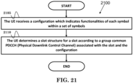
- FIG. 21 is a flow chart 2100 according to one exemplary embodiment from the perspective of a UE.
- the UE receives a configuration which indicates functionalities of each symbol within a minimum function block.
- the UE determines a slot structure for a slot according to a group common PDCCH associated with the slot and the configuration.
- the UE cannot derive a slot format according to the group common PDCCH without the configuration.
- the configuration is signaled by a RRC (Radio Resource Control) message, and could be specifically for the UE. Furthermore, the configuration indicates different functionalities of each symbol within different minimum function blocks. The UE could receive information regarding which configured set of symbols is present.
- RRC Radio Resource Control
- the minimum function block could be a basic unit for a group common PDCCH to provide information.
- the device 300 includes a program code 312 stored in the memory 310.
- the CPU 308 could execute program code 312 to enable the UE (i) to receive a configuration which indicates functionalities of each symbol within a set of symbols, and (ii) to determine a slot structure for a slot according to a group common PDCCH associated with the slot and the configuration. Furthermore, the CPU 308 can execute the program code 312 to perform all of the above-described actions and steps or others described herein.
- the base station could signal a second configuration to a second UE which indicates functionalities of each symbol within a minimum function block.
- the base station could determine for the second UE the slot structure for the slot according to the group common PDCCH associated with the slot and the second configuration.
- the base station could configure the first UE and the second UE to receive a same group common PDCCH.
- the first UE and the second UE could have different understandings regarding slot structure of a same slot according to the same group common PDCCH.
- the base station configures the UE (e.g., the first UE and/or the second UE) different functionalities of each symbol within different minimum function blocks.
- the base station could also inform the UE which configured set of symbols is present.
- concurrent channels may be established based on pulse repetition frequencies.
- concurrent channels may be established based on pulse position or offsets.
- concurrent channels may be established based on time hopping sequences.
- concurrent channels may be established based on pulse repetition frequencies, pulse positions or offsets, and time hopping sequences.
- the various illustrative logical blocks, modules, and circuits described in connection with the aspects disclosed herein may be implemented within or performed by an integrated circuit ("IC"), an access terminal, or an access point.
- the IC may comprise a general purpose processor, a digital signal processor (DSP), an application specific integrated circuit (ASIC), a field programmable gate array (FPGA) or other programmable logic device, discrete gate or transistor logic, discrete hardware components, electrical components, optical components, mechanical components, or any combination thereof designed to perform the functions described herein, and may execute codes or instructions that reside within the IC, outside of the IC, or both.
- a general purpose processor may be a microprocessor, but in the alternative, the processor may be any conventional processor, controller, microcontroller, or state machine.
- a processor may also be implemented as a combination of computing devices, e.g., a combination of a DSP and a microprocessor, a plurality of microprocessors, one or more microprocessors in conjunction with a DSP core, or any other such configuration.
- a software module e.g., including executable instructions and related data
- other data may reside in a data memory such as RAM memory, flash memory, ROM memory, EPROM memory, EEPROM memory, registers, a hard disk, a removable disk, a CD-ROM, or any other form of computer-readable storage medium known in the art.
Landscapes
- Engineering & Computer Science (AREA)
- Signal Processing (AREA)
- Computer Networks & Wireless Communication (AREA)
- Mobile Radio Communication Systems (AREA)
Claims (12)
- Verfahren einer Benutzerausrüstung, im Folgenden auch als UE bezeichnet, umfassend:die UE empfängt eine Konfiguration, die einen Typ eines minimalen Funktionsblocks angibt, wobei der Typ eines minimalen Funktionsblocks Funktionalitäten jedes Symbols innerhalb des minimalen Funktionsblocks bedeutet (2105); unddie UE bestimmt eine Zeitschlitz-Struktur für einen Zeitschlitz gemäß einem gruppengemeinsamen physikalischen Downlink-Steuerkanal, im Folgenden auch als PDCCH bezeichnet, der mit dem Zeitschlitz und der Konfiguration assoziiert ist (2110),die Konfiguration wird durch eine Funkressourcensteuerung, im Folgenden auch als RRC bezeichnet, -Nachricht signalisiert, unddie Konfiguration gibt verschiedene Typen von verschiedenen minimalen Funktionsblöcken an.
- Verfahren nach Anspruch 1, wobei die UE die Zeitschlitz-Struktur gemäß dem gruppengemeinsamen PDCCH ohne die Konfiguration nicht ableiten kann.
- Verfahren nach Anspruch 1 oder 2, wobei die Konfiguration speziell für die UE ist.
- Verfahren nach Anspruch 1, wobei die UE Informationen darüber empfängt, welcher konfigurierte minimale Funktionsblock vorhanden ist.
- Verfahren nach einem der Ansprüche 1 bis 4, wobei der minimale Funktionsblock eine Basiseinheit für einen gruppengemeinsamen PDCCH ist, um Informationen bereitzustellen.
- Verfahren einer Basisstation, umfassend:die Basisstation signalisiert einer ersten Benutzerausrüstung, im Folgenden auch als UE bezeichnet, eine erste Konfiguration, die einen Typ eines minimalen Funktionsblocks angibt, wobei der Typ eines minimalen Funktionsblocks Funktionalitäten jedes Symbols innerhalb des minimalen Funktionsblocks bedeutet (2205); unddie Basisstation bestimmt für die erste UE die Zeitschlitz-Struktur für einen Zeitschlitz gemäß einem gruppengemeinsamen physikalischen Downlink-Steuerkanal, PDCCH, der mit dem Zeitschlitz und der ersten Konfiguration assoziiert ist (2210),die Konfiguration wird durch eine Funkressourcensteuerung, im Folgenden auch als RRC bezeichnet, -Nachricht signalisiert, unddie Basisstation konfiguriert die erste UE mit verschiedenen Typen von verschiedenen minimalen Funktionsblöcken.
- Verfahren nach Anspruch 6, wobei:die Basisstation signalisiert einer zweiten UE eine zweite Konfiguration, die Funktionalitäten jedes Symbols innerhalb eines minimalen Funktionsblocks angibt, unddie Basisstation bestimmt für die zweite UE die Zeitschlitz-Struktur für den Zeitschlitz gemäß dem gruppengemeinsamen PDCCH, der mit dem Zeitschlitz und der zweiten Konfiguration assoziiert ist.
- Verfahren nach Anspruch 7, wobei die Basisstation die erste UE und die zweite UE konfiguriert, um einen gleichen gruppengemeinsamen PDCCH zu empfangen.
- Verfahren nach Anspruch 7 oder 8, wobei die erste UE und die zweite UE unterschiedliche Verständnisse hinsichtlich der Zeitschlitz-Struktur eines gleichen Zeitschlitzes gemäß dem gleichen gruppengemeinsamen PDCCH haben.
- Verfahren nach Anspruch 6, wobei die Basisstation die UE informiert, welcher konfigurierte minimale Funktionsblock vorhanden ist.
- Benutzerausrüstung, im Folgenden auch als UE bezeichnet, umfassend:eine Steuerschaltung (306);einen Prozessor (308), der in der Steuerschaltung (306) installiert ist; undeinen Speicher (310), der in der Steuerschaltung (306) installiert und betriebsfähig mit dem Prozessor (308) gekoppelt ist;wobei der Prozessor (308) konfiguriert ist, um einen Programmcode (312) auszuführen, der in dem Speicher (310) gespeichert ist, um die in einem der Ansprüche 1 bis 5 definierten Verfahrensschritte durchzuführen.
- Basisstation, umfassend:eine Steuerschaltung (306);einen Prozessor (308), der in der Steuerschaltung (306) installiert ist; undeinen Speicher (310), der in der Steuerschaltung (306) installiert und betriebsfähig mit dem Prozessor (308) gekoppelt ist;wobei der Prozessor (308) konfiguriert ist, um einen Programmcode (312) auszuführen, der in dem Speicher (310) gespeichert ist, um die in einem der Ansprüche 6 bis 10 definierten Verfahrensschritte durchzuführen.
Applications Claiming Priority (1)
| Application Number | Priority Date | Filing Date | Title |
|---|---|---|---|
| US201762457693P | 2017-02-10 | 2017-02-10 |
Publications (3)
| Publication Number | Publication Date |
|---|---|
| EP3361806A1 EP3361806A1 (de) | 2018-08-15 |
| EP3361806B1 true EP3361806B1 (de) | 2025-04-16 |
| EP3361806B8 EP3361806B8 (de) | 2025-05-28 |
Family
ID=61131895
Family Applications (1)
| Application Number | Title | Priority Date | Filing Date |
|---|---|---|---|
| EP18151139.5A Active EP3361806B8 (de) | 2017-02-10 | 2018-01-11 | Verfahren und vorrichtungen zur steuerung von kanalübertragung in einem drahtloskommunikationssystem |
Country Status (7)
| Country | Link |
|---|---|
| US (2) | US10912070B2 (de) |
| EP (1) | EP3361806B8 (de) |
| JP (2) | JP2018129795A (de) |
| KR (1) | KR102035918B1 (de) |
| CN (1) | CN108419296B (de) |
| ES (1) | ES3029613T3 (de) |
| TW (1) | TWI729258B (de) |
Families Citing this family (22)
| Publication number | Priority date | Publication date | Assignee | Title |
|---|---|---|---|---|
| JP6911137B2 (ja) * | 2017-03-03 | 2021-07-28 | 華為技術有限公司Huawei Technologies Co.,Ltd. | リソース割り当て方法および装置、ならびにリソース決定方法および装置 |
| US10645641B2 (en) * | 2017-05-05 | 2020-05-05 | Mediatek Inc. | Group common PDCCH design in NR |
| WO2019028751A1 (en) * | 2017-08-10 | 2019-02-14 | Zte Corporation | SYSTEMS AND METHODS FOR INDICATING AND DETERMINING CHANNEL STRUCTURE INFORMATION |
| WO2019033017A1 (en) * | 2017-08-10 | 2019-02-14 | Convida Wireless, Llc | ENHANCED MODE DRX PROCEDURES ENHANCED FOR NR |
| EP3704821B1 (de) * | 2017-11-02 | 2021-12-01 | Nokia Technologies Oy | Schlitzformatanzeige für eine benutzergerätegruppe in einer zelle einer basisstation |
| US10945251B2 (en) * | 2017-11-15 | 2021-03-09 | Sharp Kabushiki Kaisha | User equipments, base stations and methods |
| US10771225B2 (en) | 2017-11-17 | 2020-09-08 | Qualcomm Incorporated | Techniques and apparatuses for using mini-slots for hybrid automatic repeat request (HARQ) transmissions |
| US10779276B2 (en) | 2018-03-30 | 2020-09-15 | Apple Inc. | Self-contained slot and slot duration configuration in NR systems |
| CN119450731A (zh) | 2018-08-20 | 2025-02-14 | 韦勒斯标准与技术协会公司 | 无线通信系统中接收物理控制信道的方法及使用其的设备 |
| CN109314989A (zh) * | 2018-08-30 | 2019-02-05 | 北京小米移动软件有限公司 | 指示、确定传输单元的传输方向的方法、装置及存储介质 |
| WO2020066606A2 (en) * | 2018-09-28 | 2020-04-02 | Nec Corporation | Communication system |
| CN111356213B (zh) | 2018-12-20 | 2021-07-13 | 大唐移动通信设备有限公司 | 一种信息传输方法、基站及终端 |
| CN111385889B (zh) * | 2018-12-29 | 2024-02-02 | 华为技术有限公司 | 用于侧行链路通信的方法、网络设备以及终端设备 |
| EP3681233B1 (de) * | 2019-01-10 | 2022-06-15 | Panasonic Intellectual Property Corporation of America | Sendeempfängervorrichtung und planungsvorrichtung |
| US12185280B2 (en) * | 2019-03-28 | 2024-12-31 | Sharp Kabushiki Kaisha | Resource management for wireless backhaul networks |
| WO2020204775A1 (en) * | 2019-03-29 | 2020-10-08 | Telefonaktiebolaget Lm Ericsson (Publ) | Csi-based precoding in search space subset |
| US12034670B2 (en) * | 2019-04-09 | 2024-07-09 | Beijing Xiaomi Mobile Software Co., Ltd. | Method for feeding back data, method for transmitting data and user equipment |
| EP4042829B1 (de) * | 2019-11-21 | 2024-11-06 | Guangdong Oppo Mobile Telecommunications Corp., Ltd. | Verfahren zur pdcch-überwachung, benutzergerät, basisstation und computerlesbares medium |
| WO2021159339A1 (zh) * | 2020-02-12 | 2021-08-19 | 华为技术有限公司 | 信号传输方法及装置 |
| CN113676292B (zh) | 2020-05-15 | 2023-04-07 | 维沃移动通信有限公司 | 信息传输、harq-ack码本的生成、传输方法及设备 |
| CN114071757B (zh) * | 2020-08-06 | 2025-11-28 | 华硕电脑股份有限公司 | 无线通信系统中资源分配的方法和设备 |
| CN117426131A (zh) * | 2021-07-23 | 2024-01-19 | Oppo广东移动通信有限公司 | 通信方法及装置 |
Citations (1)
| Publication number | Priority date | Publication date | Assignee | Title |
|---|---|---|---|---|
| WO2016143968A1 (ko) * | 2015-03-12 | 2016-09-15 | 엘지전자 주식회사 | Short tti 내 제어 채널의 전송 자원을 감소시키는 방법 및 이를 사용한 기기 |
Family Cites Families (9)
| Publication number | Priority date | Publication date | Assignee | Title |
|---|---|---|---|---|
| KR100290862B1 (ko) | 1998-04-02 | 2001-07-12 | 구자홍 | 이동통신시스템에서의패킷데이터를전송하기위한슬롯의구조 |
| US7072971B2 (en) * | 2000-11-13 | 2006-07-04 | Digital Foundation, Inc. | Scheduling of multiple files for serving on a server |
| US8493873B2 (en) | 2007-06-18 | 2013-07-23 | Qualcomm Incorporated | Multiplexing of sounding signals in ACK and CQI channels |
| JP5213414B2 (ja) | 2007-10-30 | 2013-06-19 | 株式会社エヌ・ティ・ティ・ドコモ | 移動通信システム、基地局装置、ユーザ装置及び方法 |
| KR101497154B1 (ko) * | 2008-06-26 | 2015-03-02 | 엘지전자 주식회사 | Sc-fdma 시스템에서 전송 다이버시티를 이용한 데이터 전송장치 및 방법 |
| US8325685B2 (en) * | 2010-02-12 | 2012-12-04 | Research In Motion Limited | System and method for improved control channel transmit diversity |
| CN104025673B (zh) * | 2012-01-03 | 2018-06-19 | Lg电子株式会社 | 用于在无线接入系统中设置下行发射功率的方法及其设备 |
| WO2013151405A1 (ko) * | 2012-04-06 | 2013-10-10 | 엘지전자 주식회사 | 무선 접속 시스템에서 협력적 프리코딩 방법 및 이를 위한 장치 |
| WO2015142244A1 (en) * | 2014-03-21 | 2015-09-24 | Telefonaktiebolaget L M Ericsson (Publ) | System and method for improving uplink control channels for weak communication links |
-
2018
- 2018-01-11 CN CN201810026465.2A patent/CN108419296B/zh active Active
- 2018-01-11 JP JP2018002318A patent/JP2018129795A/ja active Pending
- 2018-01-11 TW TW107101108A patent/TWI729258B/zh active
- 2018-01-11 EP EP18151139.5A patent/EP3361806B8/de active Active
- 2018-01-11 KR KR1020180004075A patent/KR102035918B1/ko active Active
- 2018-01-11 ES ES18151139T patent/ES3029613T3/es active Active
- 2018-01-11 US US15/868,419 patent/US10912070B2/en active Active
-
2020
- 2020-08-19 JP JP2020138517A patent/JP2020195155A/ja active Pending
- 2020-12-17 US US17/124,707 patent/US20210105757A1/en not_active Abandoned
Patent Citations (2)
| Publication number | Priority date | Publication date | Assignee | Title |
|---|---|---|---|---|
| WO2016143968A1 (ko) * | 2015-03-12 | 2016-09-15 | 엘지전자 주식회사 | Short tti 내 제어 채널의 전송 자원을 감소시키는 방법 및 이를 사용한 기기 |
| US20180049165A1 (en) * | 2015-03-12 | 2018-02-15 | Lg Electronics Inc. | Method for reducing transmission resource of control channel in short tti, and device using same |
Also Published As
| Publication number | Publication date |
|---|---|
| TW201830907A (zh) | 2018-08-16 |
| CN108419296A (zh) | 2018-08-17 |
| US10912070B2 (en) | 2021-02-02 |
| JP2020195155A (ja) | 2020-12-03 |
| US20210105757A1 (en) | 2021-04-08 |
| KR102035918B1 (ko) | 2019-10-23 |
| KR20180092830A (ko) | 2018-08-20 |
| JP2018129795A (ja) | 2018-08-16 |
| US20180234955A1 (en) | 2018-08-16 |
| EP3361806B8 (de) | 2025-05-28 |
| TWI729258B (zh) | 2021-06-01 |
| CN108419296B (zh) | 2022-07-26 |
| ES3029613T3 (en) | 2025-06-24 |
| EP3361806A1 (de) | 2018-08-15 |
Similar Documents
| Publication | Publication Date | Title |
|---|---|---|
| EP3361806B1 (de) | Verfahren und vorrichtungen zur steuerung von kanalübertragung in einem drahtloskommunikationssystem | |
| EP3349529B1 (de) | Verfahren und vorrichtung für das timing des zeitlichen zusammenhangs zwischen steuerkanal und datenkanal in einem drahtloskommunikationssystem | |
| US11337205B2 (en) | Method and apparatus for determining numerology bandwidth in a wireless communication system | |
| EP4358463B9 (de) | Verfahren zum senden und empfangen eines gemeinsamen kanals in einem drahtlosen kommunikationssystem und vorrichtung zur unterstützung davon | |
| JP7313699B2 (ja) | ワイヤレス通信システムにおけるアップリンク制御情報を送信するための方法、およびそれを使用する装置 | |
| EP3244565B1 (de) | Verfahren und vorrichtung zur verbesserung der uplink-genehmigungen in einem gekürzten übertragungszeitintervall (tti) in einem drahtloskommunikationssystem | |
| EP3403362B1 (de) | Verfahren und benutzervorrichtung zum empfangen von downlink-kanälen sowie verfahren und basisstation zum senden von downlink-kanälen | |
| EP3525542A1 (de) | Verfahren und vorrichtung zur überwachung von ununterbrochener übertragungsanzeige in einem drahtloskommunikationssystem | |
| EP4149040A1 (de) | Verfahren und vorrichtung zur verbesserung von vorcodierungsressourcenblockgruppen in einem drahtloskommunikationssystem |
Legal Events
| Date | Code | Title | Description |
|---|---|---|---|
| PUAI | Public reference made under article 153(3) epc to a published international application that has entered the european phase |
Free format text: ORIGINAL CODE: 0009012 |
|
| STAA | Information on the status of an ep patent application or granted ep patent |
Free format text: STATUS: THE APPLICATION HAS BEEN PUBLISHED |
|
| AK | Designated contracting states |
Kind code of ref document: A1 Designated state(s): AL AT BE BG CH CY CZ DE DK EE ES FI FR GB GR HR HU IE IS IT LI LT LU LV MC MK MT NL NO PL PT RO RS SE SI SK SM TR |
|
| AX | Request for extension of the european patent |
Extension state: BA ME |
|
| STAA | Information on the status of an ep patent application or granted ep patent |
Free format text: STATUS: REQUEST FOR EXAMINATION WAS MADE |
|
| 17P | Request for examination filed |
Effective date: 20190131 |
|
| RBV | Designated contracting states (corrected) |
Designated state(s): AL AT BE BG CH CY CZ DE DK EE ES FI FR GB GR HR HU IE IS IT LI LT LU LV MC MK MT NL NO PL PT RO RS SE SI SK SM TR |
|
| STAA | Information on the status of an ep patent application or granted ep patent |
Free format text: STATUS: EXAMINATION IS IN PROGRESS |
|
| 17Q | First examination report despatched |
Effective date: 20190718 |
|
| GRAP | Despatch of communication of intention to grant a patent |
Free format text: ORIGINAL CODE: EPIDOSNIGR1 |
|
| STAA | Information on the status of an ep patent application or granted ep patent |
Free format text: STATUS: GRANT OF PATENT IS INTENDED |
|
| RIC1 | Information provided on ipc code assigned before grant |
Ipc: H04B 7/26 20060101ALN20241129BHEP Ipc: H04L 5/00 20060101ALN20241129BHEP Ipc: H04W 72/12 20090101ALN20241129BHEP Ipc: H04W 72/04 20090101AFI20241129BHEP |
|
| RIC1 | Information provided on ipc code assigned before grant |
Ipc: H04B 7/26 20060101ALN20241212BHEP Ipc: H04L 5/00 20060101ALN20241212BHEP Ipc: H04W 72/12 20090101ALN20241212BHEP Ipc: H04W 72/04 20090101AFI20241212BHEP |
|
| INTG | Intention to grant announced |
Effective date: 20241219 |
|
| GRAS | Grant fee paid |
Free format text: ORIGINAL CODE: EPIDOSNIGR3 |
|
| GRAA | (expected) grant |
Free format text: ORIGINAL CODE: 0009210 |
|
| STAA | Information on the status of an ep patent application or granted ep patent |
Free format text: STATUS: THE PATENT HAS BEEN GRANTED |
|
| GRAT | Correction requested after decision to grant or after decision to maintain patent in amended form |
Free format text: ORIGINAL CODE: EPIDOSNCDEC |
|
| P01 | Opt-out of the competence of the unified patent court (upc) registered |
Free format text: CASE NUMBER: APP_10797/2025 Effective date: 20250305 |
|
| AK | Designated contracting states |
Kind code of ref document: B1 Designated state(s): AL AT BE BG CH CY CZ DE DK EE ES FI FR GB GR HR HU IE IS IT LI LT LU LV MC MK MT NL NO PL PT RO RS SE SI SK SM TR |
|
| RAP3 | Party data changed (applicant data changed or rights of an application transferred) |
Owner name: ASUSTEK COMPUTER INC. |
|
| REG | Reference to a national code |
Ref country code: GB Ref legal event code: FG4D |
|
| REG | Reference to a national code |
Ref country code: CH Ref legal event code: PK Free format text: BERICHTIGUNG B8 Ref country code: CH Ref legal event code: EP Ref country code: DE Ref legal event code: R096 Ref document number: 602018081088 Country of ref document: DE |
|
| RIN2 | Information on inventor provided after grant (corrected) |
Inventor name: LIN, KO-CHIANG |
|
| REG | Reference to a national code |
Ref country code: IE Ref legal event code: FG4D |
|
| REG | Reference to a national code |
Ref country code: ES Ref legal event code: FG2A Ref document number: 3029613 Country of ref document: ES Kind code of ref document: T3 Effective date: 20250624 |
|
| REG | Reference to a national code |
Ref country code: NL Ref legal event code: FP |
|
| REG | Reference to a national code |
Ref country code: AT Ref legal event code: MK05 Ref document number: 1786734 Country of ref document: AT Kind code of ref document: T Effective date: 20250416 |
|
| PG25 | Lapsed in a contracting state [announced via postgrant information from national office to epo] |
Ref country code: FI Free format text: LAPSE BECAUSE OF FAILURE TO SUBMIT A TRANSLATION OF THE DESCRIPTION OR TO PAY THE FEE WITHIN THE PRESCRIBED TIME-LIMIT Effective date: 20250416 Ref country code: PT Free format text: LAPSE BECAUSE OF FAILURE TO SUBMIT A TRANSLATION OF THE DESCRIPTION OR TO PAY THE FEE WITHIN THE PRESCRIBED TIME-LIMIT Effective date: 20250818 |
|
| REG | Reference to a national code |
Ref country code: LT Ref legal event code: MG9D |
|
| PG25 | Lapsed in a contracting state [announced via postgrant information from national office to epo] |
Ref country code: NO Free format text: LAPSE BECAUSE OF FAILURE TO SUBMIT A TRANSLATION OF THE DESCRIPTION OR TO PAY THE FEE WITHIN THE PRESCRIBED TIME-LIMIT Effective date: 20250716 Ref country code: GR Free format text: LAPSE BECAUSE OF FAILURE TO SUBMIT A TRANSLATION OF THE DESCRIPTION OR TO PAY THE FEE WITHIN THE PRESCRIBED TIME-LIMIT Effective date: 20250717 |
|
| PG25 | Lapsed in a contracting state [announced via postgrant information from national office to epo] |
Ref country code: PL Free format text: LAPSE BECAUSE OF FAILURE TO SUBMIT A TRANSLATION OF THE DESCRIPTION OR TO PAY THE FEE WITHIN THE PRESCRIBED TIME-LIMIT Effective date: 20250416 |
|
| PG25 | Lapsed in a contracting state [announced via postgrant information from national office to epo] |
Ref country code: BG Free format text: LAPSE BECAUSE OF FAILURE TO SUBMIT A TRANSLATION OF THE DESCRIPTION OR TO PAY THE FEE WITHIN THE PRESCRIBED TIME-LIMIT Effective date: 20250416 |
|
| PG25 | Lapsed in a contracting state [announced via postgrant information from national office to epo] |
Ref country code: HR Free format text: LAPSE BECAUSE OF FAILURE TO SUBMIT A TRANSLATION OF THE DESCRIPTION OR TO PAY THE FEE WITHIN THE PRESCRIBED TIME-LIMIT Effective date: 20250416 |
|
| PG25 | Lapsed in a contracting state [announced via postgrant information from national office to epo] |
Ref country code: AT Free format text: LAPSE BECAUSE OF FAILURE TO SUBMIT A TRANSLATION OF THE DESCRIPTION OR TO PAY THE FEE WITHIN THE PRESCRIBED TIME-LIMIT Effective date: 20250416 |
|
| PG25 | Lapsed in a contracting state [announced via postgrant information from national office to epo] |
Ref country code: RS Free format text: LAPSE BECAUSE OF FAILURE TO SUBMIT A TRANSLATION OF THE DESCRIPTION OR TO PAY THE FEE WITHIN THE PRESCRIBED TIME-LIMIT Effective date: 20250716 |
|
| PG25 | Lapsed in a contracting state [announced via postgrant information from national office to epo] |
Ref country code: IS Free format text: LAPSE BECAUSE OF FAILURE TO SUBMIT A TRANSLATION OF THE DESCRIPTION OR TO PAY THE FEE WITHIN THE PRESCRIBED TIME-LIMIT Effective date: 20250816 |
|
| PG25 | Lapsed in a contracting state [announced via postgrant information from national office to epo] |
Ref country code: LV Free format text: LAPSE BECAUSE OF FAILURE TO SUBMIT A TRANSLATION OF THE DESCRIPTION OR TO PAY THE FEE WITHIN THE PRESCRIBED TIME-LIMIT Effective date: 20250416 |
|
| PGFP | Annual fee paid to national office [announced via postgrant information from national office to epo] |
Ref country code: NL Payment date: 20251003 Year of fee payment: 9 |
|
| PGFP | Annual fee paid to national office [announced via postgrant information from national office to epo] |
Ref country code: GB Payment date: 20251103 Year of fee payment: 9 |
|
| PG25 | Lapsed in a contracting state [announced via postgrant information from national office to epo] |
Ref country code: DK Free format text: LAPSE BECAUSE OF FAILURE TO SUBMIT A TRANSLATION OF THE DESCRIPTION OR TO PAY THE FEE WITHIN THE PRESCRIBED TIME-LIMIT Effective date: 20250416 Ref country code: SM Free format text: LAPSE BECAUSE OF FAILURE TO SUBMIT A TRANSLATION OF THE DESCRIPTION OR TO PAY THE FEE WITHIN THE PRESCRIBED TIME-LIMIT Effective date: 20250416 |
|
| PGFP | Annual fee paid to national office [announced via postgrant information from national office to epo] |
Ref country code: FR Payment date: 20251016 Year of fee payment: 9 |
|
| REG | Reference to a national code |
Ref country code: DE Ref legal event code: R097 Ref document number: 602018081088 Country of ref document: DE |
|
| PG25 | Lapsed in a contracting state [announced via postgrant information from national office to epo] |
Ref country code: CZ Free format text: LAPSE BECAUSE OF FAILURE TO SUBMIT A TRANSLATION OF THE DESCRIPTION OR TO PAY THE FEE WITHIN THE PRESCRIBED TIME-LIMIT Effective date: 20250416 |
|
| PG25 | Lapsed in a contracting state [announced via postgrant information from national office to epo] |
Ref country code: SK Free format text: LAPSE BECAUSE OF FAILURE TO SUBMIT A TRANSLATION OF THE DESCRIPTION OR TO PAY THE FEE WITHIN THE PRESCRIBED TIME-LIMIT Effective date: 20250416 Ref country code: RO Free format text: LAPSE BECAUSE OF FAILURE TO SUBMIT A TRANSLATION OF THE DESCRIPTION OR TO PAY THE FEE WITHIN THE PRESCRIBED TIME-LIMIT Effective date: 20250416 |
|
| PLBE | No opposition filed within time limit |
Free format text: ORIGINAL CODE: 0009261 |
|
| STAA | Information on the status of an ep patent application or granted ep patent |
Free format text: STATUS: NO OPPOSITION FILED WITHIN TIME LIMIT |
|
| REG | Reference to a national code |
Ref country code: CH Ref legal event code: L10 Free format text: ST27 STATUS EVENT CODE: U-0-0-L10-L00 (AS PROVIDED BY THE NATIONAL OFFICE) Effective date: 20260225 |
|
| 26N | No opposition filed |
Effective date: 20260119 |