US8325685B2 - System and method for improved control channel transmit diversity - Google Patents
System and method for improved control channel transmit diversity Download PDFInfo
- Publication number
- US8325685B2 US8325685B2 US12/705,459 US70545910A US8325685B2 US 8325685 B2 US8325685 B2 US 8325685B2 US 70545910 A US70545910 A US 70545910A US 8325685 B2 US8325685 B2 US 8325685B2
- Authority
- US
- United States
- Prior art keywords
- slot
- reference signal
- location
- symbol
- slot structure
- Prior art date
- Legal status (The legal status is an assumption and is not a legal conclusion. Google has not performed a legal analysis and makes no representation as to the accuracy of the status listed.)
- Active, expires
Links
- 238000000034 method Methods 0.000 title claims abstract description 43
- 238000004891 communication Methods 0.000 claims abstract description 29
- 230000001131 transforming effect Effects 0.000 claims description 10
- 230000009466 transformation Effects 0.000 claims description 6
- 230000021615 conjugation Effects 0.000 claims description 2
- 230000005540 biological transmission Effects 0.000 description 69
- 238000012545 processing Methods 0.000 description 26
- 230000006870 function Effects 0.000 description 15
- 230000011664 signaling Effects 0.000 description 15
- 230000000875 corresponding effect Effects 0.000 description 11
- 125000004122 cyclic group Chemical group 0.000 description 11
- 230000015654 memory Effects 0.000 description 10
- 238000013459 approach Methods 0.000 description 8
- 238000010586 diagram Methods 0.000 description 8
- 238000003860 storage Methods 0.000 description 8
- 230000015556 catabolic process Effects 0.000 description 6
- 238000006731 degradation reaction Methods 0.000 description 6
- 238000005516 engineering process Methods 0.000 description 6
- 230000003111 delayed effect Effects 0.000 description 5
- 238000010295 mobile communication Methods 0.000 description 4
- 230000008901 benefit Effects 0.000 description 3
- 238000004590 computer program Methods 0.000 description 3
- 238000013461 design Methods 0.000 description 3
- 238000001514 detection method Methods 0.000 description 3
- 238000011156 evaluation Methods 0.000 description 3
- 230000007246 mechanism Effects 0.000 description 3
- 230000003287 optical effect Effects 0.000 description 3
- 230000007480 spreading Effects 0.000 description 3
- 238000003892 spreading Methods 0.000 description 3
- 230000009471 action Effects 0.000 description 2
- 238000006243 chemical reaction Methods 0.000 description 2
- 238000013500 data storage Methods 0.000 description 2
- 230000000994 depressogenic effect Effects 0.000 description 2
- 238000012905 input function Methods 0.000 description 2
- 230000002452 interceptive effect Effects 0.000 description 2
- 239000004973 liquid crystal related substance Substances 0.000 description 2
- 238000007726 management method Methods 0.000 description 2
- 238000004519 manufacturing process Methods 0.000 description 2
- 238000012986 modification Methods 0.000 description 2
- 230000004048 modification Effects 0.000 description 2
- 230000002093 peripheral effect Effects 0.000 description 2
- 230000008569 process Effects 0.000 description 2
- 230000004044 response Effects 0.000 description 2
- 102100038530 Chorionic somatomammotropin hormone 2 Human genes 0.000 description 1
- 101710178035 Chorismate synthase 2 Proteins 0.000 description 1
- 101710152694 Cysteine synthase 2 Proteins 0.000 description 1
- 241000699670 Mus sp. Species 0.000 description 1
- 230000004913 activation Effects 0.000 description 1
- 230000004075 alteration Effects 0.000 description 1
- 230000001413 cellular effect Effects 0.000 description 1
- 239000003795 chemical substances by application Substances 0.000 description 1
- 239000004020 conductor Substances 0.000 description 1
- 230000002596 correlated effect Effects 0.000 description 1
- 238000013479 data entry Methods 0.000 description 1
- 230000006735 deficit Effects 0.000 description 1
- 230000000694 effects Effects 0.000 description 1
- 238000005562 fading Methods 0.000 description 1
- 239000000835 fiber Substances 0.000 description 1
- 230000006872 improvement Effects 0.000 description 1
- 230000003993 interaction Effects 0.000 description 1
- 230000007774 longterm Effects 0.000 description 1
- 238000013507 mapping Methods 0.000 description 1
- 239000000203 mixture Substances 0.000 description 1
- 238000012544 monitoring process Methods 0.000 description 1
- 239000013307 optical fiber Substances 0.000 description 1
- 230000010363 phase shift Effects 0.000 description 1
- 238000011176 pooling Methods 0.000 description 1
- 230000008707 rearrangement Effects 0.000 description 1
- 238000013515 script Methods 0.000 description 1
- 238000006467 substitution reaction Methods 0.000 description 1
- 238000012546 transfer Methods 0.000 description 1
- 230000001960 triggered effect Effects 0.000 description 1
Images


Classifications
-
- H—ELECTRICITY
- H04—ELECTRIC COMMUNICATION TECHNIQUE
- H04W—WIRELESS COMMUNICATION NETWORKS
- H04W72/00—Local resource management
- H04W72/04—Wireless resource allocation
- H04W72/044—Wireless resource allocation based on the type of the allocated resource
- H04W72/0446—Resources in time domain, e.g. slots or frames
-
- H—ELECTRICITY
- H04—ELECTRIC COMMUNICATION TECHNIQUE
- H04L—TRANSMISSION OF DIGITAL INFORMATION, e.g. TELEGRAPHIC COMMUNICATION
- H04L5/00—Arrangements affording multiple use of the transmission path
- H04L5/0001—Arrangements for dividing the transmission path
- H04L5/0014—Three-dimensional division
- H04L5/0023—Time-frequency-space
-
- H—ELECTRICITY
- H04—ELECTRIC COMMUNICATION TECHNIQUE
- H04L—TRANSMISSION OF DIGITAL INFORMATION, e.g. TELEGRAPHIC COMMUNICATION
- H04L5/00—Arrangements affording multiple use of the transmission path
- H04L5/0001—Arrangements for dividing the transmission path
- H04L5/0003—Two-dimensional division
- H04L5/0005—Time-frequency
- H04L5/0007—Time-frequency the frequencies being orthogonal, e.g. OFDM(A), DMT
- H04L5/001—Time-frequency the frequencies being orthogonal, e.g. OFDM(A), DMT the frequencies being arranged in component carriers
-
- H—ELECTRICITY
- H04—ELECTRIC COMMUNICATION TECHNIQUE
- H04L—TRANSMISSION OF DIGITAL INFORMATION, e.g. TELEGRAPHIC COMMUNICATION
- H04L5/00—Arrangements affording multiple use of the transmission path
- H04L5/003—Arrangements for allocating sub-channels of the transmission path
- H04L5/0037—Inter-user or inter-terminal allocation
-
- H—ELECTRICITY
- H04—ELECTRIC COMMUNICATION TECHNIQUE
- H04L—TRANSMISSION OF DIGITAL INFORMATION, e.g. TELEGRAPHIC COMMUNICATION
- H04L5/00—Arrangements affording multiple use of the transmission path
- H04L5/003—Arrangements for allocating sub-channels of the transmission path
- H04L5/0048—Allocation of pilot signals, i.e. of signals known to the receiver
-
- H—ELECTRICITY
- H04—ELECTRIC COMMUNICATION TECHNIQUE
- H04L—TRANSMISSION OF DIGITAL INFORMATION, e.g. TELEGRAPHIC COMMUNICATION
- H04L5/00—Arrangements affording multiple use of the transmission path
- H04L5/003—Arrangements for allocating sub-channels of the transmission path
- H04L5/0058—Allocation criteria
- H04L5/0062—Avoidance of ingress interference, e.g. ham radio channels
-
- H—ELECTRICITY
- H04—ELECTRIC COMMUNICATION TECHNIQUE
- H04B—TRANSMISSION
- H04B7/00—Radio transmission systems, i.e. using radiation field
- H04B7/02—Diversity systems; Multi-antenna system, i.e. transmission or reception using multiple antennas
- H04B7/04—Diversity systems; Multi-antenna system, i.e. transmission or reception using multiple antennas using two or more spaced independent antennas
- H04B7/06—Diversity systems; Multi-antenna system, i.e. transmission or reception using multiple antennas using two or more spaced independent antennas at the transmitting station
- H04B7/0613—Diversity systems; Multi-antenna system, i.e. transmission or reception using multiple antennas using two or more spaced independent antennas at the transmitting station using simultaneous transmission
- H04B7/0667—Diversity systems; Multi-antenna system, i.e. transmission or reception using multiple antennas using two or more spaced independent antennas at the transmitting station using simultaneous transmission of delayed versions of same signal
- H04B7/0669—Diversity systems; Multi-antenna system, i.e. transmission or reception using multiple antennas using two or more spaced independent antennas at the transmitting station using simultaneous transmission of delayed versions of same signal using different channel coding between antennas
-
- H—ELECTRICITY
- H04—ELECTRIC COMMUNICATION TECHNIQUE
- H04B—TRANSMISSION
- H04B7/00—Radio transmission systems, i.e. using radiation field
- H04B7/02—Diversity systems; Multi-antenna system, i.e. transmission or reception using multiple antennas
- H04B7/04—Diversity systems; Multi-antenna system, i.e. transmission or reception using multiple antennas using two or more spaced independent antennas
- H04B7/06—Diversity systems; Multi-antenna system, i.e. transmission or reception using multiple antennas using two or more spaced independent antennas at the transmitting station
- H04B7/0613—Diversity systems; Multi-antenna system, i.e. transmission or reception using multiple antennas using two or more spaced independent antennas at the transmitting station using simultaneous transmission
- H04B7/0678—Diversity systems; Multi-antenna system, i.e. transmission or reception using multiple antennas using two or more spaced independent antennas at the transmitting station using simultaneous transmission using different spreading codes between antennas
-
- H—ELECTRICITY
- H04—ELECTRIC COMMUNICATION TECHNIQUE
- H04L—TRANSMISSION OF DIGITAL INFORMATION, e.g. TELEGRAPHIC COMMUNICATION
- H04L5/00—Arrangements affording multiple use of the transmission path
- H04L5/003—Arrangements for allocating sub-channels of the transmission path
- H04L5/0053—Allocation of signaling, i.e. of overhead other than pilot signals
- H04L5/0057—Physical resource allocation for CQI
-
- H—ELECTRICITY
- H04—ELECTRIC COMMUNICATION TECHNIQUE
- H04L—TRANSMISSION OF DIGITAL INFORMATION, e.g. TELEGRAPHIC COMMUNICATION
- H04L5/00—Arrangements affording multiple use of the transmission path
- H04L5/0091—Signaling for the administration of the divided path
- H04L5/0094—Indication of how sub-channels of the path are allocated
Definitions
- the present invention relates generally to data transmission in mobile communication systems and more specifically to a user equipment (UE) specific slot structure for Physical Uplink Control CHannel (PUCCH) with transmit diversity to improve multiplexing capability.
- UE user equipment
- PUCCH Physical Uplink Control CHannel
- the terms “user equipment” and “UE” can refer to wireless devices such as mobile telephones, personal digital assistants (PDAs), handheld or laptop computers, and similar devices or other User Agents (“UAs”) that have telecommunications capabilities.
- a UE may refer to a mobile, or wireless device.
- the term “UE” may also refer to devices that have similar capabilities but that are not generally transportable, such as desktop computers, set-top boxes, or network nodes.
- LTE long-term evolution
- EPS evolved packet system
- base station or “access device” will refer to any component, such as a traditional base station or an LTE or LTE-A base station (including eNBs), that can provide a UE with access to other components in a telecommunications system.
- LTE or LTE-A base station including eNBs
- a base station provides radio access to one or more UEs.
- the base station comprises a packet scheduler for dynamically scheduling downlink traffic data packet transmissions and allocating uplink traffic data packet transmission resources among all the UEs communicating with the base station.
- the functions of the scheduler include, among others, dividing the available air interface capacity between UEs, deciding the transport channel to be used for each UE's packet data transmissions, and monitoring packet allocation and system load.
- the scheduler dynamically allocates resources for Physical Downlink Shared CHannel (PDSCH) and Physical Uplink Shared CHannel (PUSCH) data transmissions, and sends scheduling information to the UEs through a scheduling channel.
- PDSCH Physical Downlink Shared CHannel
- PUSCH Physical Uplink Shared CHannel
- control information is communicated from the UE to the base station using the PUCCH.
- RBs are allocated Resource Blocks (RBs).
- PUCCH resource blocks RBs
- RBs 100 include two PUCCH RBs 102 that are allocated at the beginning of system bandwidth and two PUCCH RBs 102 that are allocated at the end of the available system bandwidth.
- the PUCCH for a single UE is transmitted over a single RB 102 at each of the two available slots 104 within the subframe. Note that here each PUCCH RB occupies all of one slot. Generally, for a UE, the assigned PUCCH RBs in the two slots of a subframe are allocated at opposite sides of the bandwidth. Accordingly, if a UE is assigned a first RB having index 1 (one greater than the lowest index of 0) in the first slot, the UE is also assigned the RB at index N ⁇ 2 in the second slot. Accordingly, referring to FIG. 1 a , a UE may be assigned RB 106 in addition to RB 108 .
- FIG. 1 b is an illustration showing additional detail of the PUCCH RBs of FIG. 1 a .
- RBs 100 each include several symbols formed in each of the two available slots.
- Each slot includes several symbols 110 that may each contain either data or a reference signal (RS).
- the RS may be used to measure channel conditions between the UE and a base station.
- the PUCCH RB structure is summarized as a plurality of individual slots.
- a UE may be configured to initiate simultaneous transmission from multiple antennas for uplink (UL) communications.
- the communications may be referred to as multiple-input, multiple-output (MIMO) communications.
- MIMO multiple-input, multiple-output
- TxD transmit diversity
- the TxD scheme can be used to improve the coverage in an LTE-A system, to reduce required UE transmission power to reach a given level of coverage, and/or to reduce the interference caused by the transmissions.
- the multiple-access method for the PUCCH is code division multiple access (CDMA).
- CDMA code division multiple access
- OS UE-specific orthogonal sequence
- the PUCCH can be configured in several different possible formats (some existing PUCCH configurations may have 6 different configurations).
- PUCCH format designated format 2 the orthogonal resources are generated by applying cyclic shifting to a base sequence of length 12 with different cyclic shifts.
- the orthogonal resources may be referred to as cyclic shift (CS) sequences or OS sequences. Accordingly, the number of these mutually orthogonal resources may be equal to 12.
- each slot contains five DSs and one RS.
- FIGS. 2 a and 2 b are illustrations of example slot structures for format 2 PUCCHs.
- FIG. 2 a is an illustration of the slot structure including a normal CP
- FIG. 2 b is an illustration of the slot structure including an extended CP.
- the position of the DSs and RSs may be fixed as specified by a standard.
- the resource elements (e.g., subcarriers) at each DS or RS are filled using an appropriate CS sequence.
- the corresponding CS sequence is multiplied by one of the symbols generated from the encoded data to be transmitted.
- the assignment of CS sequence to the symbols in each subframe may be configured by the base station and can be signaled to the UE using higher layer signaling.
- each CS sequence can be used by at most one UE. Accordingly, in the existing configurations of LTE, the multiplexing capacity of PUCCH is limited to 12 UEs (using a single antenna) when 12 CS OSs are provided, meaning that a maximum of 12 UEs could multiplex and transmit their PUCCH on the same PUCCH RBs.
- Transparent schemes are those that use a single orthogonal sequence for the DSs of a PUCCH slot.
- the power resources of both transmit antennas are utilized while making the scheme transparent to the base station.
- Examples of this type of scheme include RF combining and slot-based precoding vector switching (PVS) as described in R1-090786, LG Electronics, “PUCCH TxD Schemes for LTE-A”, 3GPP TSG RAN WG1 #56, February 2009 and R1-091374, Nortel, “Evaluation of transmit diversity for PUCCH in LTE-A”, 3GPP TSG RAN WG1 #56b, March 2009. In these schemes, both transmit antennas use the same CS OS sequence.
- non-transparent schemes using a single OS for the DS, but different OSs for the RS may be implemented.
- this scheme include Space Time Block Code (STBC) based TxD schemes described in R1-090786, LG Electronics, “PUCCH TxD Schemes for LTE-A”, 3GPP TSG RAN WG1 #56, February 2009, R1-091374, Nortel, “Evaluation of transmit diversity for PUCCH in LTE-A”, 3GPP TSG RAN WG1 #56b, March 2009, and R1-094223, Qualcomm Europe, “Transmit Diversity for PUCCH Format 2/2a/2b”, 3GPP TSG RAN WG1 #58b, October 2009.
- STBC Space Time Block Code
- both transmit antennas are configured to use the same orthogonal sequence for transmission of DSs.
- RS transmissions using different antennas use different OSs to allow for base station channel estimation to be performed for each antenna individually. In that case, because two OSs are needed for the two RSs transmitted by the two antennas, the multiplexing capacity of these schemes is reduced by a factor of two as compared with the single antenna transmission in Rel-8.
- non-transparent schemes using two orthogonal sequences for both the DS and RS may be implemented.
- different transmit antennas use different orthogonal sequences for transmission of both DSs and RSs.
- Example of such schemes include Spatial Orthogonal-Resource Transmit Diversity (SORTD) in which the same modulated symbols are transmitted simultaneously from different antennas using different CS sequences.
- SORTD Spatial Orthogonal-Resource Transmit Diversity
- Example schemes are described in R1-090786, LG Electronics, “PUCCH TxD Schemes for LTE-A”, 3GPP TSG RAN WG1 #56, February 2009, R1-091374, Nortel, “Evaluation of transmit diversity for PUCCH in LTE-A”, 3GPP TSG RAN WG1 #56b, March 2009, R1-094223, Qualcomm Europe, “Transmit Diversity for PUCCH Format 2/2a/2b”, 3GPP TSG RAN WG1 #58b, October 2009, and R1-093052, Huawei, “Performance of UL multiple antenna transmission for PUCCH”, 3GPP TSG RAN WG1 #58, August 2009.
- the advantage of these schemes is that their performance is better than schemes that use the same OS on each antenna.
- the schemes' PUCCH multiplexing capacity is reduced by a factor of two as compared with the PUCCH multiplexing capacity of single antenna transmission in Rel-8.
- FIG. 1 a is an illustration of example Physical Uplink Control CHannel (PUCCH) resource block (RB) locations;
- PUCCH Physical Uplink Control CHannel
- RB resource block
- FIG. 1 b is an illustration showing additional detail of the PUCCH RBs of FIG. 1 a;
- FIG. 2 a is an illustration of a slot structure with a normal cyclic prefix (CP);
- FIG. 2 b is an illustration of a slot structure with an extended CP
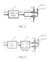
- FIG. 3 is a block diagram of Spatial Orthogonal-Resource Transmit Diversity (SORTD) illustrating how incoming information is processed and transmitted using two antennas in a multiple-input multiple-output (MIMO) configuration;
- SORTD Spatial Orthogonal-Resource Transmit Diversity
- FIG. 4 is a block diagram of Space Time Block Code (STBC) illustrating how incoming information is processed and precoded before being transmitted using two antennas in a MIMO configuration;
- STBC Space Time Block Code
- FIG. 5 is an illustration of transmission slots implemented using a UE-specific relative delay
- FIG. 6 is an illustration of transmission slots implemented using a UE-specific relative delay for an extended CP case
- FIG. 7 is an illustration of a UE-specific slot offset for STBC+SORTD with normal CP
- FIG. 8 is a diagram of a wireless communications system including a UE operable for some of the various embodiments of the disclosure
- FIG. 9 is a block diagram of a UE operable for some of the various embodiments of the disclosure.
- FIG. 10 is a diagram of a software environment that may be implemented on a UE operable for some of the various embodiments of the disclosure.
- FIG. 11 is an illustrative general purpose computer system suitable for some of the various embodiments of the disclosure.
- the present invention relates generally to data transmission in mobile communication systems and more specifically to a user equipment (UE) specific slot structure for Physical Uplink Control CHannel (PUCCH) with transmit diversity to improve multiplexing capability.
- UE user equipment
- PUCCH Physical Uplink Control CHannel
- Some implementations include a method for providing transmit diversity in wireless network communications.
- the method includes receiving an indication of a slot structure.
- the slot structure identifies at least a first location of a reference signal within a slot.
- the method includes transmitting a first reference signal within a first slot using a first antenna. A location of the first reference signal within the first slot is determined by the slot structure.
- the method includes transmitting a second reference signal within the first slot using a second antenna. A location of the second reference signal within the first slot is determined by the slot structure.
- the method includes receiving an indication of a slot structure.
- the slot structure identifies at least a location of a first reference signal and a location of a second reference signal.
- the method includes transmitting a first and a second symbol within a first slot using a first antenna and a first orthogonal resource.
- the second symbol is transmitted after the first symbol.
- the method includes transforming the first and second symbols to form a first transformed symbol and a second transformed symbol, and transmitting the transformed first symbol and the transformed second symbol within the first slot using a second antenna and the first orthogonal resource.
- the first transformed symbol is transmitted after the second transformed symbol.
- the method includes transmitting a first reference signal within the first slot at a location determined by the slot structure.
- the first reference signal is transmitted using a first antenna.
- the method includes transmitting a second reference signal within the first slot at a second location determined by the slot structure.
- the second reference signal is transmitted using a second antenna.
- implementations include a method for providing transmit diversity in wireless network communications.
- the method includes receiving an indication of a slot structure.
- the slot structure identifies at least one location of a reference signal within a slot and identifies a first and second orthogonal code.
- the method includes encoding one or more reference signals using the first orthogonal code and the second orthogonal code identified by the slot structure, and transmitting the encoded one or more reference signal within a first slot.
- a location of the encoded one or more reference signal is determined by the slot structure.
- the method includes receiving an indication of a Physical Uplink Control Channel (PUCCH) timing advance, transmitting a first reference signal of a PUCCH at a delay relative to downlink frame timing at least partially determined by the PUCCH timing advance, and transmitting a second reference signal of a PUCCH at a delay relative to downlink frame timing at least partially determined by the PUCCH timing advance.
- the method includes transmitting a reference signal in a Physical Uplink Shared Channel (PUSCH) at a delay relative to downlink frame timing at least partially determined by a different timing advance than the PUCCH timing advance.
- PUSCH Physical Uplink Shared Channel
- a base station comprising a processor configured to transmit an indication of a slot structure.
- the slot structure identifies at least a first location of a reference signal within a slot.
- the processor is configured to receive a first reference signal within a first slot. A location of the first reference signal within the first slot is determined by the slot structure.
- the processor is configured to receive a second reference signal within the first slot. A location of the second reference signal within the first slot is determined by the slot structure.
- a base station comprising a processor configured to transmit an indication of a slot structure.
- the slot structure identifies at least one location of a reference signal within a slot and identifies a first and second orthogonal code.
- the processor is configured to receive one or more encoded reference signals within a first slot. A location of the one or more encoded reference signal is determined by the slot structure.
- the one or more encoded reference signals are encoded using the first orthogonal code and the second orthogonal code identified by the slot structure.
- a user equipment comprising a processor configured to receive an indication of a slot structure.
- the slot structure identifies at least a first location of a reference signal within a slot.
- the processor is configured to transmit a first reference signal within a first slot using a first antenna. A location of the first reference signal within the first slot is determined by the slot structure.
- the processor is configured to transmit a second reference signal within the first slot using a second antenna. A location of the second reference signal within the first slot is determined by the slot structure.
- a component may be, but is not limited to being, a process running on a processor, a processor, an object, an executable, a thread of execution, a program, and/or a computer.
- an application running on a computer and the computer can be a component.
- One or more components may reside within a process and/or thread of execution and a component may be localized on one computer and/or distributed between two or more computers.
- exemplary is used herein to mean serving as an example, instance, or illustration. Any aspect or design described herein as “exemplary” is not necessarily to be construed as preferred or advantageous over other aspects or designs.
- the disclosed subject matter may be implemented as a system, method, apparatus, or article of manufacture using standard programming and/or engineering techniques to produce software, firmware, hardware, or any combination thereof to control a computer or processor based device to implement aspects detailed herein.
- article of manufacture (or alternatively, “computer program product”) as used herein is intended to encompass a computer program accessible from any computer-readable device, carrier, or media.
- computer readable media can include but are not limited to magnetic storage devices (e.g., hard disk, floppy disk, magnetic strips . . . ), optical disks (e.g., compact disk (CD), digital versatile disk (DVD) . . . ), smart cards, and flash memory devices (e.g., card, stick).
- a carrier wave can be employed to carry computer-readable electronic data such as those used in transmitting and receiving electronic mail or in accessing a network such as the Internet or a local area network (LAN).
- LAN local area network
- multiple antennas may be used to transmit PUCCH communications from a UE to a base station.
- a suitable transmit diversity (TxD) scheme may be implemented to improve the coverage in an LTE-A system.
- TxD schemes for PUCCH may be configured to use orthogonal resources to assist in distinguishing between the transmissions of each antenna.
- existing TxD schemes allocate unique orthogonal resources for each antenna, the existing schemes use excessive amounts of the available orthogonal resources limiting the number of UEs that can be serviced using the same PUCCH RB in a MIMO system.
- the existing schemes make it difficult to separate PUCCH transmissions from each antenna.
- the first problem is overuse of the limited number of available orthogonal resources.
- a base station needs to estimate the channel coefficients of each of the two transmit antennas.
- different orthogonal sequences should be used for transmission of RSs from the two transmit antennas.
- the PUCCH multiplexing capacity may be reduced to 6 for two antenna TxD as two orthogonal sequences are needed for each UE, one for each antenna.
- FIG. 3 is a block diagram of SORTD illustrating how incoming information is processed and transmitted using two antennas in a MIMO configuration.
- information bits b i enter the FEC/Modulator block 12 to generate 10 quadrature phase-shift keying (QPSK) modulated symbols d i .
- QPSK quadrature phase-shift keying
- Each modulated symbol s i is mapped to antenna i.
- the symbol s i over antenna i where i may be equal to 1 or 2 is multiplied by the orthogonal CS sequence c i , where c 1 is not the same as c 2 .
- the resultant value is then mapped to the corresponding DS in the assigned RB and is transmitted on the antenna corresponding to the symbol.
- the RSs are also transmitted using different CS sequences for different antennas.
- each UE uses two OSs, one for each antenna.
- the assignment of CS OS to UEs can be made in various ways. One example of the assignment is shown below in Table 1.
- rows correspond to UEs that can be multiplexed in the same time-frequency resource, and columns correspond to symbol times, where S i denotes the i th symbol in the transmission slot.
- the underlined and non-underlined values illustrate the locations of RSs and DSs, respectively, within each slot.
- the numbers within the table are the index of the OS (namely, the index of cyclic shift sequences) ranging from 1 to 12. These are logical indices of OS. In practice, as in Rel. 8, these indices can be mapped to actual indices based on the symbol number.
- each table is used to represent different orthogonal codes that may be used when transmitting each symbol.
- the index below S i in each row of the table shows the orthogonal sequences are used by the corresponding UE at the i th symbol.
- UE# 1 uses CS sequences CS- 1 and CS- 7 for transmitting via each antenna.
- UE# 2 uses CS sequences CS- 2 and CS- 8 for transmitting via each antenna.
- SORTD at most 6 UEs, each with two antennas, can be multiplexed within the same RB.
- FIG. 4 is a block diagram of STBC illustrating how incoming information is processed and precoded before being transmitted using two antennas in a MIMO configuration.
- FEC/modulator block 12 performs similarly as described in FIG. 3 , although in FIG. 4 s 1 and s 2 need not be equal.
- MIMO precoder 14 may be an Alamouti encoder that performs over pairs of modulated symbols and generates symbols for pairs of DSs in the subframe.
- s 1 and s 2 For a given pair (s 1 and s 2 ) of modulated symbols, at the first DS (i.e., symbol S 1 ), s 1 is mapped to antenna 1 and s 2 is mapped to antenna 2 . At the second DS, however, ⁇ s 2 ′′ is mapped to antenna 1 and s 1 is mapped to antenna 2 .
- the corresponding symbols of both antennas are multiplied by the same CS sequence CS- 1 .
- the resultant sequence for each antenna is then mapped to the subcarriers of the corresponding DS and is transmitted using OFDM. Similar to SORTD, the RS is transmitted from the two antennas using two different CS sequences.
- s 1 and s 2 may be transformed using any of negation, complex conjugation, or leaving one of the symbols unchanged.
- a first transformation is performed on s 1 while a different transformation is applied to s 2 .
- a second problem with STBC is that of orphan symbols.
- each block of STBC requires one pair of modulated symbols. Because each slot for PUCCH contains five modulated symbols for DS transmissions (see FIGS. 2 a and 2 b ), after making two pairs of symbols, one symbol in each slot remains unpaired and leads to an orphan symbol that requires special treatment.
- the orphan symbol problem may be mitigated by transmitting the orphan symbol from both antennas at the same time.
- no spatial diversity gain is obtained.
- the antennas are correlated, there are chances that transmitted signals are added destructively at the receiver resulting in a performance degradation.
- only one antenna may be used for transmission of the orphan symbols.
- the orphan symbols of two slots may be paired with one another. In that case, an MMSE receiver can be used to detect the code block composed of these two symbols.
- some performance loss may result.
- a UE-specific slot structure in which the position of RSs in each slot is different from UE to UE.
- the rearrangement of RS positions allows for the allocation of additional orthogonal resources for additional UEs to be multiplexed within the same RB, leading to increased multiplexing capability for the PUCCH.
- the RS arrangement of the present system provides performance gains when compared to conventional RS arrangements wherein both slot structures are examined with the same number of multiplexed UEs.
- SORTD may be used for transmission of orphan symbols.
- the multiplexing capacity may be increased, for example, from 6 to 9.
- UE-specific slot structures or UE-specific slot offsets are defined so that RS locations of different UEs are distributed across the slots.
- congestion of CS resources at specific symbols e.g., RS symbols of Rel-8
- the additional available OSs may be used to multiplex more UEs within the same RB.
- non-transparent TxD schemes that use one OS for data transmission use two orthogonal sequences for RS transmissions limiting their multiplexing capacity to 6 UEs.
- 6 orthogonal sequences are used and 6 orthogonal sequences are left unused.
- UE-specific slot structures or UE-specific slot offsets may be used so that RS locations of different UEs are distributed across the slot.
- congestion of CS resources at specific symbols (RS symbols of Rel-8) is avoided and unused orthogonal sequences in all symbols are made available.
- the newly available orthogonal sequences can be used to multiplex additional UEs within the same RB.
- Non-transparent TxD schemes may use one OS for DSs and two OSs for RSs.
- UE-specific slot structures are established such that the RS of different UEs are not transmitted on fixed symbols of the slot.
- the utilization of OSs are evenly distributed across the symbols of one slot and multiplexing capacity is increased.
- Table 3 and Table 4 illustrate example UE-specific slot structures implementing the present system.
- Table 3 and Table 4 show an example of the structure for normal CP and extended CP, respectively.
- RS transmissions for each UE are offset from one another allowing different UEs to use the same OS when transmitting RSs using two antennas. There is no collision in this example, because UEs that use the same OS when transmitting their RSs, transmit the RSs in different symbols.
- UE# 1 is assigned symbols # 1 and # 5 for RS transmissions.
- UE# 1 is assigned CS- 1 and CS- 10 (cyclic shift orthogonal sequences with indices 1 and 10 ) for use in the RS transmission from antennas 1 and 2 .
- UE# 1 is assigned CS- 1 .
- UE# 2 also uses CS- 10 when transmitting its RSs, however UE# 2 is configured to transmit RSs in symbols 2 and 6 , so the RSs transmitted by UE# 2 are offset from those of UE# 1 .
- UE# 3 also uses CS- 10 when transmitting its RSs, however UE# 3 is configured to transmit RSs in symbols 3 and 7 , so the RSs transmitted by UE# 3 are offset from those of UE# 1 and UE# 2 .
- CS- 10 can be reused by UE# 1 , UE# 2 , and UE# 3 while maintaining orthogonality between RSs.
- symbols # 3 and # 7 are to be used for UE# 6 's RS transmissions.
- UE# 6 is assigned CS- 6 and CS- 11 for UE# 6 's RS transmission on antennas 1 and 2 , respectively, while UE# 6 's DS will be transmitted on symbols 1 , 2 , 4 , 5 and 6 using CS- 6 .
- Table 3 and Table 4 show slot structures of the present system that allow all 12 OS resources to be fully utilized without compromising OS orthogonality. This leads to increased multiplexing capability for UEs.
- the number of multiplexed UEs for normal CP equals 9, whereas 10 UEs can be multiplexed in the case of extended CP.
- the present system may be used to increase the multiplexing capacity of the supported TxD schemes (e.g., category 2 described above) from 6 to 9 for normal CP and 10 for extended CP, respectively.
- a UE may use different slot structures in the two slots of a subframe.
- a UE that uses symbols S 1 and S 5 for RS transmission in the first slot of a subframe may be configured to use symbols S 9 and S 13 (instead of S 8 and S 12 ) in the second slot.
- a first slot structure may be defined for a first slot within a subframe, while a second slot structure having a different configuration than the first slot structure is defined for the second slot of the subframe.
- the present system is generally backward compatible to LTE Rel-8 UEs.
- Backward compatibility is facilitated because sequences for both DS and RS are chosen from the same CS OS set. Accordingly, rearranging the location of RS and DS does not break the orthogonality amongst UEs, even for Rel-8 UEs.
- UE-specific slot structures illustrated in Table 3 and Table 4 respectively, there exists 3 or 2 Rel-8 slot structures that can be reserved and assigned specifically to Rel-8 UEs.
- Those UE-specific slot structures are transparent to Rel-8 UEs, and, accordingly, Rel-8 and Rel-10 UEs may be mixed in such structures with some Rel-8 UEs being assigned the Rel-8 compatible slots, while the remaining slot structures are assigned to Rel-10 UEs. Because OS orthogonality is maintained in the described UE-specific slot structure, performance degradation for Rel-8 UEs is minimized.
- Table 5 illustrates an alternative to Table 3 in which 4 UEs (UE 1 , UE 2 , UE 3 , and UE 4 ) are Rel-8 UEs and so use a single OS to encode their RSs as they only are configured to use a single antenna.
- UE 5 -UE 10 may be reserved for Rel-10 UEs. With this scheme up to 10 (Rel-8 and Rel-10) UEs can be multiplexed in the same RB.
- Rel-10 UE be backward compatible to Rel-8, the above mentioned Rel-8 UE could also include those Rel-10 UEs which work in a Rel-8 transmission mode, for example in a single antenna mode.
- UE indices that correspond to new slot structures can be assigned to Rel-8 UEs. Because a Rel-8 UE uses only one OS at a time, Rel-8 UE's may ignore the assigned slot structure and only use the assigned OS (by Rel-8 slot structure) instead. For example, referring to Table 3, if the slot identified by UE index 3 is considered for a Rel-8 UE, the UE can use OS index 3 with a Rel-8 slot structure rather than the slot structure considered for UE index 3 . Because, OS index 10 is not used by this UE, the orthogonality of OS among different UEs is preserved.
- some of the UE indices can be specifically dedicated to Rel-8 UEs, possibly allowing for a more efficient multiplexing of Rel-10 and Rel-8 UEs.
- some PUCCH RBs can be completely reserved and configured for Rel-8 UEs to make sure there are enough resources to support legacy Rel-8 UEs.
- increasing numbers of the present UE-specific slot structures may be configured to support both Rel-8 and Rel-10 UEs, or support only Rel-10 UEs.
- the present system may be used in circumstances where the potential locations of the RS are restricted. For example, if extended CP symbols S 1 and S 6 are not allowed to carry RS (for example to avoid performance degradation for high speed UEs), alternative configurations of the present slot structure can be implemented to maintain support for more than 6 UEs. In some cases, the number of supported UEs in this case may be less than 10.
- a base station will configure a slot allocation for a UE.
- the slot allocation may then be communicated to the UE.
- the slot allocation includes information (or implicitly identifies information) that allow the UE to determine the slot structure to be used when transmitting to the base station using PUCCH.
- the assignment of slot structure and OS i.e., slot allocation
- the cqi-pucch resource index is semi-statically signaled to the UE via higher layer signaling such as RRC signaling.
- This resource index which is unique for each UE in each subframe, may be used by the UE to determine the slot structure, including which RB and which OS indices should be used in the corresponding subframe.
- a one-to-one mapping between this resource index and the slot structure, the OS, and the RB used for transmitting the PUCCH can be defined in LTE-A.
- one resource index value may correspond to a particular RB reserved for PUCCH format 2/2a/2b and the configuration (i.e. slot structure and corresponding OS) in each row shown in Table 3 and Table 4. Accordingly, without any signaling overhead, each UE can recognize the specific slot structure and the associated OSs based upon the UE's resource index for PUCCH format 2.
- the assignment of slot structure and OS can be implicitly signaled to the UE by any reserved field in the SPS activation signaling, for example, indicated by the ‘TPC command for PUCCH’.
- Other reserved fields are also possible.
- the assignment of slot structure and OS may be explicitly conveyed to the Rel-10 UE, semi-statically or dynamically, through higher layer signaling or physical layer control signaling.
- explicit signaling can be performed by signaling an index for RB, an index for the OS of DS, an index for the first OS of RS, and an index for the second OS of RS.
- the base station may signal a bitmap indicating the slot structure.
- a table-based or list-based scheme may be used. For example, a table such as those illustrated in Table 3 or Table 4 may be established and assigned an index that is used to represent different schemes known to both the base station and the UE. In that case, the table index as well as the cqi-pucch resource index is signaled to the UE. This resource index tells the UE which row of the specified table is assigned to the UE. Generally, any indicator may be used to signal the slot structure to a UE.
- the base station does not have to be bound to a specific slot structure and OS assignment scheme, such as those illustrated in Table 3 and Table 4. Instead, the base station may have several alternative schemes, which can be used depending upon traffic loading, channel conditions. For example, if there are more than 3 Rel-8 UEs that need to be scheduled in the same RB, the base station can switch from Table 3 to a scheme that provides additional Rel-8 slot structures such as that illustrated in Table 5. Alternatively, in high Doppler frequency channel conditions, the base station can switch from Table 4 to a scheme that avoids using symbols S 1 and S 6 for RS transmissions.
- the assignment of OS to slot structures may be defined such that the CS indices in different slot structures are relatively far apart from one another. Accordingly, when loading is low, different slot structures may be assigned to the UEs (OS balancing) and, automatically, UEs use CS indices that are far apart from one another. This may result in improved orthogonality amongst UEs resulting in more accurate channel estimation and data detection.
- the base station may select specific slot structures based upon traffic loading and available PUCCH resources.
- loading is low, namely, there are a small number of UEs that require to transmit PUCCH, the base station may assign different slot structures (for example, the first several rows of Table 3) to the UEs.
- This kind of slot structure assignment prevents unbalanced utilization of the OS resources.
- the base station could assign all available slot structures (for example, all the slot structures illustrated in either Table 3 or Table 4).
- it is preferable to allocate the slot structure and OS so that OS utilization is distributed evenly across DS and RS.
- the base station may also be configured to assign different slot structures to different UEs based upon their mobility or based upon uplink interference knowledge. For example, the base station may assign slot structures having more balanced RS positions (RS on symbols 2 and 6 , for example) to UEs with relatively high mobility to maintain channel estimation performance, while the base station may assign slot structures with unbalanced RS locations (for example RS on symbols 1 and 5 ) to UEs with low mobility where the location of the RSs does not strongly affect channel estimation performance.
- RS positions RS on symbols 2 and 6 , for example
- unbalanced RS locations for example RS on symbols 1 and 5
- the present system may be implemented as a time shift of each slot assigned to each UE, with the time shift causing different UEs to transmit DS and RS at different times or in different symbols.
- a UE-specific relative delay or timing advance may be implemented between PUCCHs while using the existing PUCCH slot structure. This timing advance would be different from the one in Release 8 LTE that adjusts uplink frame timing.
- the UE-specific delay or timing advance would adjust the delay at which PUCCH is transmitted relative to downlink frame timing, but not the delay at which PUSCH is transmitted relative to downlink frame timing.
- FIGS. 5 and 6 are illustrations of transmission slots being implemented using a UE-specific relatively delay and illustrate normal and extended CP cases, respectively. In FIGS. 5 and 6 symbol times are indicated with T with maximum indices corresponding to the 12 or 14 OFDM symbols in a subframe. Consecutive, similarly shaded symbols on a row represent one subframe transmission from a single UE.
- UE# 2 is set to have zero delay relative to normal PUCCH timing. Accordingly, DS transmission 20 is the first of UE# 2 's transmission and occurs during symbol T 1 . Conversely, UE# 1 is set to begin transmitting one symbol earlier. Accordingly, UE# 1 's first transmission 22 occurs during symbol T 14 . By transmitting one symbol earlier, the RS transmissions of UEs # 1 and # 2 are offset from one another. As such, both UE# 1 and UE# 2 can use OS CS- 10 without interfering with one another. Similarly, UE# 3 is set to begin transmitting one symbol later. Accordingly, UE# 3 's first transmission 24 occurs during symbol T 2 . By transmitting one symbol later, the RS transmissions of UEs # 1 , # 2 and # 3 are offset from one another. As such, UEs # 1 , # 2 and # 3 can use CS- 10 without interfering with one another.
- up to 9 UEs can simultaneously transmit on the PUCCH resource without inter-user interference. This is enabled by delaying or advancing a UEs transmission relative to normal PUCCH timing by one OFDM symbol. (In the example of FIG. 5 , UEs 1 , 4 , and 7 are advanced by one OFDM symbol, and UEs 3 , 6 , and 9 are each delayed by one OFDM symbol.) Due to the delay, different groups of UEs overlap in time on the first or last two OFDM symbols of a subframe. The different transmission of each UE is distinguished using shading.
- FIG. 6 shows an implementation of the UE-specific relative delay when extended CP is used. Because there is only one RS per slot and there are more possible positions for the RS within the slot, slightly more UEs can be multiplexed within the same subframe than when the normal CP is used. In this case, up to 10 UEs may be multiplexed with UE-specific relative delay with extended CP, as compared to 9 with the normal CP.
- the present slot offset approach is generally compatible with Rel-8 as the position of an RS within a slot is unchanged, enabling the same channel estimation approaches to be used. Furthermore, when a single UE occupies the PUCCH, impairments such as channel non-stationarity or multipath have the same performance degradation as Rel-8.
- the present slot offset may result in a more complicated PUSCH transmission implementation. For example, because PUSCH is not delayed, if a UE is to transmit a PUSCH in the next subframe after the UE transmits a delayed PUCCH, the UE must simultaneously transmit the PUCCH and PUSCH for one OFDM symbol in the first or last symbol of a subframe. Accordingly, transmission may be constrained so that a UE is not required to transmit a PUSCH in the next subframe after the UE transmits a delayed PUCCH.
- multi-user detection receivers can be more difficult to implement, because more groups of users can interfere with one another. For example, if there is multipath fading, a UE in a first group of users is interfered with only by the other UEs in the first group over most of the frame, but can be interfered with by a mixture of users from the first and second or third groups of UEs in up to the first or last symbol of a subframe. For example, referring to FIG. 5 , during transmission of DS 26, UE# 2 may be interfered with by DS transmission 28 , which may be transmitted by a different user in a different group. However, because this interference only result in 2 of the 14 symbols in a UE's subframe, and the use of multiuser detection receivers for PUCCH may not be widespread, this disadvantage may not be severe.
- the present UE-specific slot offset is similar to the UE specific slot structure in that Rel-8 UEs can be transmitted on the same subcarriers as those with a UE specific slot offset.
- the Rel-8 UEs may transmit with no offset.
- UE-specific slot offset is UE-specific UL frame timing shift, i.e. shifting the UL frame timing by ⁇ 1 symbols to obtain the desired RS time shift.
- SRS and PUSCH can interfere: While scheduling might avoid this, if SRS is used often, it might be better to have UEs transmit SRS with a ⁇ 1 symbol offset, to synchronize them with the rest of the cell.
- a combination of STBC and SORTD is used to provide a TxD scheme for PUCCH.
- Four symbols in each slot form two pairs of symbols which are transmitted using an Alamouti precoder, as described above. After encoding, a single orphan symbol remains in each slot.
- the orphan symbols are transmitted using the SORTD method described above.
- each slot includes three types of symbols: RS using two orthogonal sequences for the two antennas, DS using one orthogonal sequence (DS 1 ) (DS 1 symbols are transmitted using the Alamouti code), and DS using two orthogonal sequences (DS 2 ) (the DS 2 symbols are the orphan symbols and are transmitted using SORTD).
- the multiplexing capacity of this method is equal to 6. This limitation is set by RS and DS 2 types of symbols which use two orthogonal sequences.
- this scheme may provide an increased multiplexing capacity.
- Table 6 and Table 7 below illustrate examples of UE-specific slot structure for STBC+SORTD with normal CP and extended CP, respectively.
- underlined values represent RS, while the values in italics and double-underlined represent a symbol including an orphan symbol (DS 2 ) that has been encoded in accordance with SORTD.
- FIG. 7 is an illustration of a UE-specific slot offset for STBC+SORTD with normal CP.
- S i denotes the i th symbol in the slot.
- the OSs are indexed from 1 to 12.
- the indices below S i show the OSs used by the corresponding UE at the i th symbol.
- UE# 1 is assigned symbols # 1 and # 5 for its RS transmission, and CS- 1 and CS- 9 are allocated for its RS transmission from antennas 1 and 2 , while for the DS 1 symbols, which will be transmitted on symbols 2 , 3 , 6 , and 7 , CS- 1 will be used, and consecutive symbols such as ⁇ S 2 S 3 ⁇ and ⁇ S 6 S 7 ⁇ will be transmitted after Alamouti coding.
- DS 2 will be transmitted on symbol S 3 using two orthogonal sequences, CS- 1 and CS- 9 , one for each antenna.
- the pattern used for the UE-Specific offset based approach in FIG. 7 may be similar to the approach illustrated in Table 6. However, in FIG. 7 some UEs transmit with a delay or advance, which allows the same slot structure to be used for all UEs. The ability to have the same slot structure for all UEs in FIG. 7 results from the pattern of Table 6 in which the location of the orphan symbol (DS 2 ) relative to the location of RS is the same for all slot structures.
- Table 6 a UE-specific slot structure is given in which the location of the orphan symbol (DS 2 ) relative to the location of RS is the same for all UEs. As shown in Table 6, most of the paired symbols (for Alamouti encoding) are apart from each other by one symbol (RS or orphan symbol). This may lead to performance degradation at high UE speeds.
- An alternative pattern is shown in Table 8, in which the number of paired symbols in which the individual symbols are next to each other is increased over that shown in Table 6.
- a potential disadvantage of the example implementation illustrated in Table 6 and Table 8 is that they include two symbols in which only 10 OS are used (see symbols S 1 and S 7 of Table 6 and symbols S 3 and S 5 of Table 8), whereas in the other 5 symbols all 12 OS are used.
- Other schemes may be developed in which the use of OS resources is more balanced across a particular slot.
- An example of such a scheme is shown in Table 9.
- the drawback of this scheme is that for UE # 8 , there exists a pair of Alamouti encoded symbols which have two other symbols between them. This may introduce some performance degradation for this UE at high speeds.
- the present TxD scheme allow for configurations that accommodate a maximum number of UEs in each RB. It should be noted, however, that the examples shown in Table 6, Table 7, Table 8, Table 9, and FIG. 7 are only examples as other slot configuration including alternative allocations of RS, DS 1 and DS 2 to available symbols may be implemented.
- FIG. 8 illustrates a wireless communications system including an embodiment of a UE 10 .
- UE 10 is operable for implementing aspects of the disclosure, but the disclosure should not be limited to these implementations.
- the UE 10 may take various forms including a wireless handset, a pager, a personal digital assistant (PDA), a portable computer, a tablet computer, a laptop computer. Many suitable devices combine some or all of these functions.
- the UE 10 is not a general purpose computing device like a portable, laptop or tablet computer, but rather is a special-purpose communications device such as a mobile phone, a wireless handset, a pager, a PDA, or a telecommunications device installed in a vehicle.
- the UE 10 may also be a device, include a device, or be included in a device that has similar capabilities but that is not transportable, such as a desktop computer, a set-top box, or a network node.
- the UE 10 may support specialized activities such as gaming, inventory control, job control, and/or task management functions, and so on.
- the UE 10 includes a display 702 .
- the UE 10 also includes a touch-sensitive surface, a keyboard or other input keys generally referred as 704 for input by a user.
- the keyboard may be a full or reduced alphanumeric keyboard such as QWERTY, Dvorak, AZERTY, and sequential types, or a traditional numeric keypad with alphabet letters associated with a telephone keypad.
- the input keys may include a trackwheel, an exit or escape key, a trackball, and other navigational or functional keys, which may be inwardly depressed to provide further input function.
- the UE 10 may present options for the user to select, controls for the user to actuate, and/or cursors or other indicators for the user to direct.
- the UE 10 may further accept data entry from the user, including numbers to dial or various parameter values for configuring the operation of the UE 10 .
- the UE 10 may further execute one or more software or firmware applications in response to user commands. These applications may configure the UE 10 to perform various customized functions in response to user interaction. Additionally, the UE 10 may be programmed and/or configured over-the-air, for example from a wireless base station, a wireless access point, or a peer UE 10 .
- the various applications executable by the UE 10 are a web browser, which enables the display 702 to show a web page.
- the web page may be obtained via wireless communications with a wireless network access node, a cell tower, a peer UE 10 , or any other wireless communication network or system 700 .
- the network 700 is coupled to a wired network 708 , such as the Internet.
- the UE 10 has access to information on various servers, such as a server 710 .
- the server 710 may provide content that may be shown on the display 702 .
- the UE 10 may access the network 700 through a peer UE 10 acting as an intermediary, in a relay type or hop type of connection.
- FIG. 9 shows a block diagram of the UE 10 . While a variety of known components of UEs 110 are depicted, in an embodiment a subset of the listed components and/or additional components not listed may be included in the UE 10 .
- the UE 10 includes a digital signal processor (DSP) 802 and a memory 804 .
- DSP digital signal processor
- the UE 10 may further include an antenna and front end unit 806 , a radio frequency (RF) transceiver 808 , an analog baseband processing unit 810 , a microphone 812 , an earpiece speaker 814 , a headset port 816 , an input/output interface 818 , a removable memory card 820 , a universal serial bus (USB) port 822 , a short range wireless communication sub-system 824 , an alert 826 , a keypad 828 , a liquid crystal display (LCD), which may include a touch sensitive surface 830 , an LCD controller 832 , a charge-coupled device (CCD) camera 834 , a camera controller 836 , and a global positioning system (GPS) sensor 838 .
- the UE 10 may include another kind of display that does not provide a touch sensitive screen.
- the DSP 802 may communicate directly with the memory 804 without passing through the input/output interface 818 .
- the DSP 802 or some other form of controller or central processing unit operates to control the various components of the UE 10 in accordance with embedded software or firmware stored in memory 804 or stored in memory contained within the DSP 802 itself.
- the DSP 802 may execute other applications stored in the memory 804 or made available via information carrier media such as portable data storage media like the removable memory card 820 or via wired or wireless network communications.
- the application software may comprise a compiled set of machine-readable instructions that configure the DSP 802 to provide the desired functionality, or the application software may be high-level software instructions to be processed by an interpreter or compiler to indirectly configure the DSP 802 .
- the antenna and front end unit 806 may be provided to convert between wireless signals and electrical signals, enabling the UE 10 to send and receive information from a cellular network or some other available wireless communications network or from a peer UE 10 .
- the antenna and front end unit 806 may include multiple antennas to support beam forming and/or multiple input multiple output (MIMO) operations.
- MIMO operations may provide spatial diversity which can be used to overcome difficult channel conditions and/or increase channel throughput.
- the antenna and front end unit 806 may include antenna tuning and/or impedance matching components, RF power amplifiers, and/or low noise amplifiers.
- the RF transceiver 808 provides frequency shifting, converting received RF signals to baseband and converting baseband transmit signals to RF.
- a radio transceiver or RF transceiver may be understood to include other signal processing functionality such as modulation/demodulation, coding/decoding, interleaving/deinterleaving, spreading/despreading, inverse fast Fourier transforming (IFFT)/fast Fourier transforming (FFT), cyclic prefix appending/removal, and other signal processing functions.
- IFFT inverse fast Fourier transforming
- FFT fast Fourier transforming
- cyclic prefix appending/removal and other signal processing functions.
- the description here separates the description of this signal processing from the RF and/or radio stage and conceptually allocates that signal processing to the analog baseband processing unit 810 and/or the DSP 802 or other central processing unit.
- the analog base band processing unit 810 may provide various analog processing of inputs and outputs, for example analog processing of inputs from the microphone 812 and the headset 816 and outputs to the earpiece 814 and the headset 816 .
- the analog base band processing unit 810 may have ports for connecting to the built-in microphone 812 and the earpiece speaker 814 that enable the UE 10 to be used as a cell phone.
- the analog base band processing unit 810 may further include a port for connecting to a headset or other hands-free microphone and speaker configuration.
- the analog base band processing unit 810 may provide digital-to-analog conversion in one signal direction and analog-to-digital conversion in the opposing signal direction.
- at least some of the functionality of the analog base band processing unit 810 may be provided by digital processing components, for example by the DSP 802 or by other central processing units.
- the DSP 802 may perform modulation/demodulation, coding/decoding, interleaving/deinterleaving, spreading/despreading, inverse fast Fourier transforming (IFFT)/fast Fourier transforming (FFT), cyclic prefix appending/removal, and other signal processing functions associated with wireless communications.
- IFFT inverse fast Fourier transforming
- FFT fast Fourier transforming
- cyclic prefix appending/removal and other signal processing functions associated with wireless communications.
- CDMA code division multiple access
- the DSP 802 may perform modulation, coding, interleaving, inverse fast Fourier transforming, and cyclic prefix appending, and for a receiver function the DSP 802 may perform cyclic prefix removal, fast Fourier transforming, deinterleaving, decoding, and demodulation.
- DSP 802 may perform similar functions to the OFDMA transmitter, but may additionally perform a fast Fourier transform.
- SC-FDMA single carrier frequency division multiple access
- the DSP 802 may communicate with a wireless network via the analog baseband processing unit 810 .
- the communication may provide Internet connectivity, enabling a user to gain access to content on the Internet and to send and receive e-mail or text messages.
- the input/output interface 818 interconnects the DSP 802 and various memories and interfaces.
- the memory 804 and the removable memory card 820 may provide software and data to configure the operation of the DSP 802 .
- the interfaces may be the USB interface 822 and the short range wireless communication sub-system 824 .
- the USB interface 822 may be used to charge the UE 10 and may also enable the UE 10 to function as a peripheral device to exchange information with a personal computer or other computer system.
- the short range wireless communication sub-system 824 may include an infrared port, a Bluetooth interface, an IEEE 802.11 compliant wireless interface, or any other short range wireless communication sub-system, which may enable the UE 10 to communicate wirelessly with other nearby mobile devices and/or wireless base stations.
- the input/output interface 818 may further connect the DSP 802 to the alert 826 that, when triggered, causes the UE 10 to provide a notice to the user, for example, by ringing, playing a melody, or vibrating.
- the alert 826 may serve as a mechanism for alerting the user to any of various events such as an incoming call, a new text message, and an appointment reminder by silently vibrating, or by playing a specific pre-assigned melody for a particular caller.
- the keypad 828 couples to the DSP 802 via the interface 818 to provide one mechanism for the user to make selections, enter information, and otherwise provide input to the UE 10 .
- the keyboard 828 may be a full or reduced alphanumeric keyboard such as QWERTY, Dvorak, AZERTY and sequential types, or a traditional numeric keypad with alphabet letters associated with a telephone keypad.
- the input keys may include a trackwheel, an exit or escape key, a trackball, and other navigational or functional keys, which may be inwardly depressed to provide further input function.
- Another input mechanism may be the LCD 830 , which may include touch screen capability and also display text and/or graphics to the user.
- the LCD controller 832 couples the DSP 802 to the LCD 830 .
- the CCD camera 834 if equipped, enables the UE 10 to take digital pictures.
- the DSP 802 communicates with the CCD camera 834 via the camera controller 836 .
- a camera operating according to a technology other than Charge Coupled Device cameras may be employed.
- the GPS sensor 838 is coupled to the DSP 802 to decode global positioning system signals, thereby enabling the UE 10 to determine its position.
- Various other peripherals may also be included to provide additional functions, e.g., radio and television reception.
- FIG. 10 illustrates a software environment 902 that may be implemented by the DSP 802 .
- the DSP 802 executes operating system drivers 904 that provide a platform from which the rest of the software operates.
- the operating system drivers 904 provide drivers for the UE hardware with standardized interfaces that are accessible to application software.
- the operating system drivers 904 include application management services (“AMS”) 906 that transfer control between applications running on the UE 10 .
- AMS application management services
- FIG. 10 also shown in FIG. 10 are a web browser application 908 , a media player application 910 , and Java applets 912 .
- the web browser application 908 configures the UE 10 to operate as a web browser, allowing a user to enter information into forms and select links to retrieve and view web pages.
- the media player application 910 configures the UE 10 to retrieve and play audio or audiovisual media.
- the Java applets 912 configure the UE 10 to provide games, utilities, and other functionality.
- a component 914 might provide functionality described
- FIG. 11 illustrates an example of a system 1000 that includes a processing component 1010 suitable for implementing one or more embodiments disclosed herein.
- the system 1000 might include network connectivity devices 1020 , random access memory (RAM) 1030 , read only memory (ROM) 1040 , secondary storage 1050 , and input/output (I/O) devices 1060 .
- RAM random access memory
- ROM read only memory
- secondary storage 1050 secondary storage
- I/O input/output
- some of these components may not be present or may be combined in various combinations with one another or with other components not shown.
- These components might be located in a single physical entity or in more than one physical entity. Any actions described herein as being taken by the processor 1010 might be taken by the processor 1010 alone or by the processor 1010 in conjunction with one or more components shown or not shown in the drawing.
- the processor 1010 executes instructions, codes, computer programs, or scripts that it might access from the network connectivity devices 1020 , RAM 1030 , ROM 1040 , or secondary storage 1050 (which might include various disk-based systems such as hard disk, floppy disk, or optical disk). While only one processor 1010 is shown, multiple processors may be present. Thus, while instructions may be discussed as being executed by a processor, the instructions may be executed simultaneously, serially, or otherwise by one or multiple processors.
- the processor 1010 may be implemented as one or more CPU chips.
- the network connectivity devices 1020 may take the form of modems, modem banks, Ethernet devices, universal serial bus (USB) interface devices, serial interfaces, token ring devices, fiber distributed data interface (FDDI) devices, wireless local area network (WLAN) devices, radio transceiver devices such as code division multiple access (CDMA) devices, global system for mobile communications (GSM) radio transceiver devices, worldwide interoperability for microwave access (WiMAX) devices, and/or other well-known devices for connecting to networks.
- FDDI fiber distributed data interface
- WLAN wireless local area network
- radio transceiver devices such as code division multiple access (CDMA) devices, global system for mobile communications (GSM) radio transceiver devices, worldwide interoperability for microwave access (WiMAX) devices, and/or other well-known devices for connecting to networks.
- CDMA code division multiple access
- GSM global system for mobile communications
- WiMAX worldwide interoperability for microwave access
- the network connectivity devices 1020 might also include one or more transceiver components 1025 capable of transmitting and/or receiving data wirelessly in the form of electromagnetic waves, such as radio frequency signals or microwave frequency signals. Alternatively, the data may propagate in or on the surface of electrical conductors, in coaxial cables, in waveguides, in optical media such as optical fiber, or in other media.
- the transceiver component 1025 might include separate receiving and transmitting units or a single transceiver.
- Information transmitted or received by the transceiver 1025 may include data that has been processed by the processor 1010 or instructions that are to be executed by processor 1010 . Such information may be received from and outputted to a network in the form, for example, of a computer data baseband signal or signal embodied in a carrier wave.
- the data may be ordered according to different sequences as may be desirable for either processing or generating the data or transmitting or receiving the data.
- the baseband signal, the signal embedded in the carrier wave, or other types of signals currently used or hereafter developed may be referred to as the transmission medium and may be generated according to several methods well known to one skilled in the art.
- the RAM 1030 might be used to store volatile data and perhaps to store instructions that are executed by the processor 1010 .
- the ROM 1040 is a non-volatile memory device that typically has a smaller memory capacity than the memory capacity of the secondary storage 1050 .
- ROM 1040 might be used to store instructions and perhaps data that are read during execution of the instructions. Access to both RAM 1030 and ROM 1040 is typically faster than to secondary storage 1050 .
- the secondary storage 1050 is typically comprised of one or more disk drives or tape drives and might be used for non-volatile storage of data or as an over-flow data storage device if RAM 1030 is not large enough to hold all working data. Secondary storage 1050 may be used to store programs that are loaded into RAM 1030 when such programs are selected for execution.
- the I/O devices 1060 may include liquid crystal displays (LCDs), touch screen displays, keyboards, keypads, switches, dials, mice, track balls, voice recognizers, card readers, paper tape readers, printers, video monitors, or other well-known input/output devices.
- the transceiver 1025 might be considered to be a component of the I/O devices 1060 instead of or in addition to being a component of the network connectivity devices 1020 .
- Some or all of the I/O devices 1060 may be substantially similar to various components depicted in the previously described drawing of the UE 10 , such as the display 702 and the input 704 .
Landscapes
- Engineering & Computer Science (AREA)
- Signal Processing (AREA)
- Computer Networks & Wireless Communication (AREA)
- Mobile Radio Communication Systems (AREA)
- Radio Transmission System (AREA)
Abstract
Description
| TABLE 1 | |||||||
| UE | S1 | S2 | S3 | S4 | S5 | S6 | S7 |
| 1 | 1, 7 | 1, 7 | 1, 7 | 1, 7 | 1, 7 | 1, 7 | 1, 7 |
| 2 | 2, 8 | 2, 8 | 2, 8 | 2, 8 | 2, 8 | 2, 8 | 2, 8 |
| 3 | 3, 9 | 3, 9 | 3, 9 | 3, 9 | 3, 9 | 3, 9 | 3, 9 |
| 4 | 4, 10 | 4, 10 | 4, 10 | 4, 10 | 4, 10 | 4, 10 | 4, 10 |
| 5 | 5, 11 | 5, 11 | 5, 11 | 5, 11 | 5, 11 | 5, 11 | 5, 11 |
| 6 | 6, 12 | 6, 12 | 6, 12 | 6, 12 | 6, 12 | 6, 12 | 6, 12 |
| TABLE 2 | |||||||||
| UE | S1 | S2 | S3 | S4 | S5 | S6 | S7 | ||
| 1 | 1 | 1, 7 | 1 | 1 | 1 | 1, 7 | 1 | ||
| 2 | 2 | 2, 8 | 2 | 2 | 2 | 2, 8 | 2 | ||
| 3 | 3 | 3, 9 | 3 | 3 | 3 | 3, 9 | 3 | ||
| 4 | 4 | 4, 10 | 4 | 4 | 4 | 4, 10 | 4 | ||
| 5 | 5 | 5, 11 | 5 | 5 | 5 | 5, 11 | 5 | ||
| 6 | 6 | 6, 12 | 6 | 6 | 6 | 6, 12 | 6 | ||
| TABLE 3 | |||||||
| UE | S1 | S2 | S3 | S4 | S5 | S6 | S7 |
| 1 | 1, 10 | 1 | 1 | 1 | 1, 10 | 1 | 1 |
| 2 | 2 | 2, 10 | 2 | 2 | 2 | 2, 10 | 2 |
| 3 | 3 | 3 | 3, 10 | 3 | 3 | 3 | 3, 10 |
| 4 | 4, 11 | 4 | 4 | 4 | 4, 11 | 4 | 4 |
| 5 | 5 | 5, 11 | 5 | 5 | 5 | 5, 11 | 5 |
| 6 | 6 | 6 | 6, 11 | 6 | 6 | 6 | 6, 11 |
| 7 | 7, 12 | 7 | 7 | 7 | 7, 12 | 7 | 7 |
| 8 | 8 | 8, 12 | 8 | 8 | 8 | 8, 12 | 8 |
| 9 | 9 | 9 | 9, 12 | 9 | 9 | 9 | 9, 12 |
| TABLE 4 | ||||||||
| UE | S1 | S2 | S3 | S4 | S5 | S6 | ||
| 1 | 1 | 1 | 1 | 1 | 1, 11 | 1 | ||
| 2 | 2 | 2 | 2 | 2, 11 | 2 | 2 | ||
| 3 | 3 | 3 | 3, 11 | 3 | 3 | 3 | ||
| 4 | 4 | 4, 11 | 4 | 4 | 4 | 4 | ||
| 5 | 5, 11 | 5 | 5 | 5 | 5 | |||
| 6 | 6 | 6 | 6 | 6 | 6 | 6, 12 | ||
| 7 | 7 | 7 | 7 | 7 | 7, 12 | 7 | ||
| 8 | 8 | 8 | 8 | 8, 12 | 8 | 8 | ||
| 9 | 9 | 9 | 9, 12 | 9 | 9 | 9 | ||
| 10 | 10 | 10, 12 | 10 | 10 | 10 | 10 | ||
| TABLE 5 | |||||||
| UE | S1 | S2 | S3 | S4 | S5 | S6 | S7 |
| 1 | 1 | 1 | 1 | 1 | 1 | 1 | 1 |
| 2 | 2 | 2 | 2 | 2 | 2 | 2 | 2 |
| 3 | 3 | 3 | 3 | 3 | 3 | 3 | 3 |
| 4 | 4 | 4 | 4 | 4 | 4 | 4 | 4 |
| 5 | 5, 11 | 5 | 5 | 5 | 5, 11 | 5 | 5 |
| 6 | 6 | 6, 11 | 6 | 6 | 6 | 6, 11 | 6 |
| 7 | 7 | 7 | 7, 11 | 7 | 7 | 7 | 7, 11 |
| 8 | 8, 12 | 8 | 8 | 8 | 8, 12 | 8 | 8 |
| 9 | 9 | 9, 12 | 9 | 9 | 9 | 9, 12 | 9 |
| 10 | 10 | 10 | 10, 12 | 10 | 10 | 10 | 10, 12 |
| TABLE 6 | |||||||
| UE | S1 | S2 | S3 | S4 | S5 | S6 | S7 |
| 1 | 1, 9 | 1 | 1, 9 | 1 | 1,9 | 1 | 1 |
| 2 | 2 | 2, 9 | 2 | 2, 9 | 2 | 2, 9 | 2 |
| 3 | 3 | 3 | 3, 10 | 3 | 3, 10 | 3 | 3, 10 |
| 4 | 4 | 4, 10 | 4 | 4, 10 | 4 | 4, 10 | 4 |
| 5 | 5, 11 | 5 | 5, 11 | 5 | 5, 11 | 5 | 5 |
| 6 | 6 | 6, 11 | 6 | 6, 11 | 6 | 6, 11 | 6 |
| 7 | 7 | 7 | 7, 12 | 7 | 7, 12 | 7 | 7, 12 |
| 8 | 8 | 8, 12 | 8 | 8, 12 | 8 | 8, 12 | 8 |
| TABLE 7 | ||||||||
| UE | S1 | S2 | S3 | S4 | S5 | S6 | ||
| 1 | 1, 10 | 1 | 1, 10 | 1 | 1 | 1 | ||
| 2 | 2 | 2, 10 | 2 | 2, 10 | 2 | 2 | ||
| 3 | 3 | 3 | 3 | 3 | 3, 10 | 3, 10 | ||
| 4 | 4, 11 | 4 | 4 | 4, 11 | 4 | 4 | ||
| 5 | 5 | 5 | 5, 11 | 5 | 5, 11 | 5 | ||
| 6 | 6 | 6, 11 | 6 | 6 | 6 | 6, 11 | ||
| 7 | 7, 12 | 7 | 7, 12 | 7 | 7 | 7 | ||
| 8 | 8 | 8, 12 | 8 | 8, 12 | 8 | 8 | ||
| 9 | 9 | 9 | 9 | 9 | 9, 12 | 9, 12 | ||
| TABLE 8 | |||||||
| UE | S1 | S2 | S3 | S4 | S5 | S6 | S7 |
| 1 | 1, 9 | 1 | 1 | 1, 9 | 1, 9 | 1 | 1 |
| 2 | 2 | 2, 9 | 2 | 2 | 2 | 2, 9 | 2, 9 |
| 3 | 3 | 3 | 3, 10 | 3, 10 | 3 | 3 | 3, 10 |
| 4 | 4, 10 | 4, 10 | 4 | 4 | 4 | 4, 10 | 4 |
| 5 | 5, 11 | 5 | 5 | 5, 11 | 5, 11 | 5 | 5 |
| 6 | 6 | 6, 11 | 6 | 6 | 6 | 6, 11 | 6, 11 |
| 7 | 7 | 7 | 7, 12 | 7, 12 | 7 | 7 | 7, 12 |
| 8 | 8, 12 | 8, 12 | 8 | 8 | 8 | 8, 12 | 8 |
| TABLE 9 | |||||||
| UE | S1 | S2 | S3 | S4 | S5 | S6 | S7 |
| 1 | 1, 9 | 1 | 1 | 1, 9 | 1, 9 | 1 | 1 |
| 2 | 2 | 2, 9 | 2 | 2 | 2 | 2, 9 | 2, 9 |
| 3 | 3 | 3 | 3, 10 | 3, 10 | 3 | 3 | 3, 10 |
| 4 | 4, 10 | 4, 10 | 4 | 4 | 4 | 4, 10 | 4 |
| 5 | 5, 11 | 5 | 5, 11 | 5 | 5, 11 | 5 | 5 |
| 6 | 6 | 6, 11 | 6 | 6 | 6 | 6, 11 | 6, 11 |
| 7 | 7 | 7 | 7, 12 | 7, 12 | 7 | 7 | 7, 12 |
| 8 | 8 | 8, 12 | 8 | 8 | 8, 12 | 8, 12 | 8 |
Claims (13)
Priority Applications (6)
| Application Number | Priority Date | Filing Date | Title |
|---|---|---|---|
| US12/705,459 US8325685B2 (en) | 2010-02-12 | 2010-02-12 | System and method for improved control channel transmit diversity |
| EP11742855.7A EP2534803B1 (en) | 2010-02-12 | 2011-02-11 | System and method for improved control channel transmit diversity |
| CA2789026A CA2789026C (en) | 2010-02-12 | 2011-02-11 | System and method for improved control channel transmit diversity |
| PCT/US2011/024506 WO2011100533A1 (en) | 2010-02-12 | 2011-02-11 | System and method for improved control channel transmit diversity |
| CN201180018834.XA CN102893569B (en) | 2010-02-12 | 2011-02-11 | For the system and method for control channel transmit diversity improved |
| US13/692,695 US8891496B2 (en) | 2010-02-12 | 2012-12-03 | System and method for improved control channel transmit diversity |
Applications Claiming Priority (1)
| Application Number | Priority Date | Filing Date | Title |
|---|---|---|---|
| US12/705,459 US8325685B2 (en) | 2010-02-12 | 2010-02-12 | System and method for improved control channel transmit diversity |
Related Child Applications (1)
| Application Number | Title | Priority Date | Filing Date |
|---|---|---|---|
| US13/692,695 Continuation US8891496B2 (en) | 2010-02-12 | 2012-12-03 | System and method for improved control channel transmit diversity |
Publications (2)
| Publication Number | Publication Date |
|---|---|
| US20110200018A1 US20110200018A1 (en) | 2011-08-18 |
| US8325685B2 true US8325685B2 (en) | 2012-12-04 |
Family
ID=44368143
Family Applications (2)
| Application Number | Title | Priority Date | Filing Date |
|---|---|---|---|
| US12/705,459 Active 2030-10-30 US8325685B2 (en) | 2010-02-12 | 2010-02-12 | System and method for improved control channel transmit diversity |
| US13/692,695 Active 2030-04-19 US8891496B2 (en) | 2010-02-12 | 2012-12-03 | System and method for improved control channel transmit diversity |
Family Applications After (1)
| Application Number | Title | Priority Date | Filing Date |
|---|---|---|---|
| US13/692,695 Active 2030-04-19 US8891496B2 (en) | 2010-02-12 | 2012-12-03 | System and method for improved control channel transmit diversity |
Country Status (5)
| Country | Link |
|---|---|
| US (2) | US8325685B2 (en) |
| EP (1) | EP2534803B1 (en) |
| CN (1) | CN102893569B (en) |
| CA (1) | CA2789026C (en) |
| WO (1) | WO2011100533A1 (en) |
Cited By (3)
| Publication number | Priority date | Publication date | Assignee | Title |
|---|---|---|---|---|
| US20110319106A1 (en) * | 2010-06-25 | 2011-12-29 | Jong Bu Lim | Method for grouping access points in high speed mobile environment and communication system using the method |
| US20130094463A1 (en) * | 2010-02-12 | 2013-04-18 | Research In Motion Limited | System and Method for Improved Control Channel Transmit Diversity |
| US20150188599A1 (en) * | 2013-12-31 | 2015-07-02 | Futurewei Technologies Inc. | Wireless electronic device with switchable antenna system |
Families Citing this family (27)
| Publication number | Priority date | Publication date | Assignee | Title |
|---|---|---|---|---|
| KR101682004B1 (en) * | 2010-03-16 | 2016-12-05 | 삼성전자주식회사 | Apparatus and method for drx operating in wireless communication system |
| CN105813108B (en) * | 2010-03-29 | 2019-11-01 | Lg电子株式会社 | Method and apparatus for the measurement to the Inter-Cell Interference Coordination in radio communications system |
| WO2011122874A2 (en) * | 2010-03-31 | 2011-10-06 | Samsung Electronics Co., Ltd. | Indexing resources for transmission of acknowledgement signals in multi-cell tdd communication systems |
| EP3407522B1 (en) * | 2010-05-04 | 2020-07-15 | LG Electronics Inc. | Method and apparatus for transmitting a reference signal in a wireless communication system |
| US8902844B2 (en) * | 2010-07-06 | 2014-12-02 | Lg Electronics Inc. | Method and device for allocating wireless resources for a machine type communication device in a wireless communication system |
| WO2012076043A1 (en) * | 2010-12-08 | 2012-06-14 | Nokia Siemens Networks Oy | Resource allocation in a wireless communication system |
| US9215050B2 (en) | 2011-09-23 | 2015-12-15 | Lg Electronics Inc. | Method and apparatus for transmitting uplink control information in wireless communication system |
| US20150009921A1 (en) * | 2011-11-17 | 2015-01-08 | Docomo Innovations, Inc | Method for scheduling and mu-mimo transmission over ofdm via interference alignment based on user multipath intensity profile information |
| CN103166880A (en) * | 2011-12-15 | 2013-06-19 | 中国移动通信集团公司 | Sending method and receiving method of uploading demodulating pilot frequency, base station and moving relay |
| US9166663B2 (en) * | 2012-12-14 | 2015-10-20 | Futurewei Technologies, Inc. | System and method for open-loop MIMO communications in a SCMA communications system |
| WO2014113088A1 (en) * | 2013-01-17 | 2014-07-24 | Intel IP Corporation | Systems and methods for generating a discovery signal in a device-to-device or network communication |
| CN107534453B (en) * | 2015-02-19 | 2020-07-21 | 瑞典爱立信有限公司 | Wireless node, radio node and method for transmitting and receiving reference signals |
| CN105025570B (en) * | 2015-05-15 | 2019-04-02 | 南京邮电大学 | The design method of mobile position estimation based on Alamouti coding |
| US9949260B2 (en) * | 2015-10-23 | 2018-04-17 | Futurewei Technologies Co., Ltd. | Apparatus and method for transmit power control command transmission |
| US10038488B2 (en) * | 2016-12-22 | 2018-07-31 | Qualcomm Incorporated | PUCCH transmit diversity with one-symbol STBC |
| EP3566367B1 (en) * | 2017-01-06 | 2021-04-28 | Telefonaktiebolaget LM Ericsson (publ) | Methods, device and node for adapting a numerology depending on a position of a wireless device |
| CN113067688A (en) * | 2017-02-01 | 2021-07-02 | Oppo广东移动通信有限公司 | Communication method, network equipment and terminal |
| US10912070B2 (en) * | 2017-02-10 | 2021-02-02 | Asustek Computer Inc. | Method and apparatus for control channel transmission in a wireless communication system |
| EP3479615B1 (en) * | 2017-05-05 | 2022-01-19 | Telefonaktiebolaget LM Ericsson (publ) | Method and device for configuring semi-persistent scheduling |
| US11343039B2 (en) | 2017-05-15 | 2022-05-24 | Telefonaktiebolaget Lm Ericsson (Publ) | Demodulation reference signaling for mini-slots |
| WO2019034672A1 (en) * | 2017-08-15 | 2019-02-21 | Fraunhofer-Gesellschaft zur Förderung der angewandten Forschung e.V. | Wireless network and devices |
| US10374768B2 (en) | 2017-10-02 | 2019-08-06 | Telefonaktiebolaget Lm Ericsson (Publ) | Efficient SRS resource indication methods |
| EP4236101A3 (en) | 2017-10-02 | 2024-02-28 | Telefonaktiebolaget LM Ericsson (publ) | Efficient srs resource indication methods |
| WO2019088787A1 (en) * | 2017-11-03 | 2019-05-09 | 엘지전자 주식회사 | Method for transmitting and receiving plurality of slot-based long pucchs in wireless communication system and apparatus therefor |
| CN110381568B (en) | 2018-04-13 | 2022-07-12 | 维沃移动通信有限公司 | Method for monitoring physical downlink control channel, user equipment and network side equipment |
| US20230093484A1 (en) * | 2021-09-23 | 2023-03-23 | Apple Inc. | Systems and methods for de-correlating coded signals in dual port transmissions |
| CN114173222B (en) * | 2022-02-11 | 2022-04-15 | 上海英哈科技有限公司 | Internet of things equipment, internet of things data server and corresponding operation method |
Citations (9)
| Publication number | Priority date | Publication date | Assignee | Title |
|---|---|---|---|---|
| US20080101310A1 (en) * | 2006-10-26 | 2008-05-01 | Thomas Louis Marzetta | MIMO Communication System with Variable Slot Structure |
| US20080318608A1 (en) * | 2007-06-19 | 2008-12-25 | Nec Corporation | Method and device for assigning reference signal sequences in mobile communications system |
| US20090034505A1 (en) | 2007-07-30 | 2009-02-05 | Samsung Electronics Co., Ltd. | Method and apparatus for transmitting and receiving different signal types in communication systems |
| US20090046645A1 (en) * | 2007-08-13 | 2009-02-19 | Pierre Bertrand | Uplink Reference Signal Sequence Assignments in Wireless Networks |
| US20100002800A1 (en) | 2008-07-02 | 2010-01-07 | Lg Electronics Inc. | Method and apparatus of transmitting reference signal for uplink transmission |
| US20100027450A1 (en) | 2006-11-01 | 2010-02-04 | Qualcomm Incorporated | Multiplexing of control and data with varying power offsets in a SC-FDMA system |
| US20100034174A1 (en) | 2007-01-19 | 2010-02-11 | Ntt Docomo, Inc. | Base station apparatus and communication control method |
| US20100034312A1 (en) * | 2008-07-29 | 2010-02-11 | Tarik Muharemovic | Reference Signal Resource Allocation for Single User MIMO |
| US20100182975A1 (en) * | 2006-10-04 | 2010-07-22 | Qualcomm Incorporated | Uplink ack transmission for sdma in a wireless communication system |
Family Cites Families (4)
| Publication number | Priority date | Publication date | Assignee | Title |
|---|---|---|---|---|
| US8331478B2 (en) * | 2010-01-08 | 2012-12-11 | Research In Motion Limited | Transmit diversity using low code rate spatial multiplexing |
| US8325685B2 (en) * | 2010-02-12 | 2012-12-04 | Research In Motion Limited | System and method for improved control channel transmit diversity |
| CA2813242C (en) * | 2010-10-01 | 2016-06-07 | Research In Motion Limited | Orthogonal resource selection transmit diversity |
| WO2012060630A2 (en) * | 2010-11-02 | 2012-05-10 | Lg Electronics Inc. | Method and apparatus for transmitting control information in radio communication system |
-
2010
- 2010-02-12 US US12/705,459 patent/US8325685B2/en active Active
-
2011
- 2011-02-11 EP EP11742855.7A patent/EP2534803B1/en active Active
- 2011-02-11 CA CA2789026A patent/CA2789026C/en active Active
- 2011-02-11 CN CN201180018834.XA patent/CN102893569B/en active Active
- 2011-02-11 WO PCT/US2011/024506 patent/WO2011100533A1/en active Application Filing
-
2012
- 2012-12-03 US US13/692,695 patent/US8891496B2/en active Active
Patent Citations (9)
| Publication number | Priority date | Publication date | Assignee | Title |
|---|---|---|---|---|
| US20100182975A1 (en) * | 2006-10-04 | 2010-07-22 | Qualcomm Incorporated | Uplink ack transmission for sdma in a wireless communication system |
| US20080101310A1 (en) * | 2006-10-26 | 2008-05-01 | Thomas Louis Marzetta | MIMO Communication System with Variable Slot Structure |
| US20100027450A1 (en) | 2006-11-01 | 2010-02-04 | Qualcomm Incorporated | Multiplexing of control and data with varying power offsets in a SC-FDMA system |
| US20100034174A1 (en) | 2007-01-19 | 2010-02-11 | Ntt Docomo, Inc. | Base station apparatus and communication control method |
| US20080318608A1 (en) * | 2007-06-19 | 2008-12-25 | Nec Corporation | Method and device for assigning reference signal sequences in mobile communications system |
| US20090034505A1 (en) | 2007-07-30 | 2009-02-05 | Samsung Electronics Co., Ltd. | Method and apparatus for transmitting and receiving different signal types in communication systems |
| US20090046645A1 (en) * | 2007-08-13 | 2009-02-19 | Pierre Bertrand | Uplink Reference Signal Sequence Assignments in Wireless Networks |
| US20100002800A1 (en) | 2008-07-02 | 2010-01-07 | Lg Electronics Inc. | Method and apparatus of transmitting reference signal for uplink transmission |
| US20100034312A1 (en) * | 2008-07-29 | 2010-02-11 | Tarik Muharemovic | Reference Signal Resource Allocation for Single User MIMO |
Non-Patent Citations (1)
| Title |
|---|
| International Search Report and Written Opinion for PCT Application No. PCT/US2011/024506, mailed Apr. 6, 2011. |
Cited By (6)
| Publication number | Priority date | Publication date | Assignee | Title |
|---|---|---|---|---|
| US20130094463A1 (en) * | 2010-02-12 | 2013-04-18 | Research In Motion Limited | System and Method for Improved Control Channel Transmit Diversity |
| US8891496B2 (en) * | 2010-02-12 | 2014-11-18 | Blackberry Limited | System and method for improved control channel transmit diversity |
| US20110319106A1 (en) * | 2010-06-25 | 2011-12-29 | Jong Bu Lim | Method for grouping access points in high speed mobile environment and communication system using the method |
| US8868117B2 (en) * | 2010-06-25 | 2014-10-21 | Samsung Electronics Co., Ltd. | Method for grouping access points in high speed mobile environment and communication system using the method |
| US20150188599A1 (en) * | 2013-12-31 | 2015-07-02 | Futurewei Technologies Inc. | Wireless electronic device with switchable antenna system |
| US9100100B2 (en) * | 2013-12-31 | 2015-08-04 | Futurewei Technologies, Inc. | Wireless electronic device with switchable antenna system |
Also Published As
| Publication number | Publication date |
|---|---|
| CA2789026A1 (en) | 2011-08-18 |
| EP2534803B1 (en) | 2018-06-13 |
| EP2534803A4 (en) | 2017-02-15 |
| EP2534803A1 (en) | 2012-12-19 |
| US8891496B2 (en) | 2014-11-18 |
| CN102893569A (en) | 2013-01-23 |
| CN102893569B (en) | 2016-01-13 |
| US20110200018A1 (en) | 2011-08-18 |
| CA2789026C (en) | 2016-11-29 |
| WO2011100533A1 (en) | 2011-08-18 |
| US20130094463A1 (en) | 2013-04-18 |
Similar Documents
| Publication | Publication Date | Title |
|---|---|---|
| US8891496B2 (en) | System and method for improved control channel transmit diversity | |
| US9295051B2 (en) | Systems and methods for bundling resource blocks in a wireless communication network | |
| US9258095B2 (en) | Uplink demodulation reference signal design for MIMO transmission | |
| CA2786034C (en) | Method and system for enabling resource block bundling in lte-a systems | |
| US8644238B2 (en) | Demodulation reference signals in a communication system | |
| US20170156132A1 (en) | Design on Enhanced Control Channel For Wireless System | |
| US9531515B2 (en) | Local area optimized uplink control channel | |
| CN115314083B (en) | Method and node for adaptive demodulation reference signal density | |
| US8665993B2 (en) | Orthogonal resource selection transmit diversity | |
| US8934427B2 (en) | Method and device for generating reference signal in cellular mobile communication system | |
| KR20120086291A (en) | Method and system of multi-layer beamforming | |
| KR20100124000A (en) | Method for allocating resource block in long term evolution system | |
| WO2011052273A1 (en) | Downlink control signalling for downlink mimo | |
| US8908492B2 (en) | Orthogonal resource selection transmit diversity and resource assignment | |
| EP2378698A2 (en) | Systems and methods for bundling resource blocks in a wireless communication system | |
| WO2013023170A1 (en) | Orthogonal resource selection transmit diversity and resource assignment | |
| KR20130121656A (en) | Radio resource allocation method for control channel and method for receiving the same |
Legal Events
| Date | Code | Title | Description |
|---|---|---|---|
| AS | Assignment |
Owner name: RESEARCH IN MOTION LIMITED, CANADA Free format text: ASSIGNMENT OF ASSIGNORS INTEREST;ASSIGNORS:TAZEH MAHALLEH, MASOUD EBRAHIMI;JIA, YONGKANG;XU, HUA;SIGNING DATES FROM 20100114 TO 20110114;REEL/FRAME:026431/0397 Owner name: RESEARCH IN MOTION CORPORATION, DELAWARE Free format text: ASSIGNMENT OF ASSIGNORS INTEREST;ASSIGNOR:HARRISON, ROBERT MARK;REEL/FRAME:026431/0351 Effective date: 20110114 |
|
| AS | Assignment |
Owner name: RESEARCH IN MOTION LIMITED, ONTARIO Free format text: ASSIGNMENT OF ASSIGNORS INTEREST;ASSIGNOR:RESEARCH IN MOTION CORPORATION;REEL/FRAME:026996/0022 Effective date: 20110927 |
|
| AS | Assignment |
Owner name: RESEARCH IN MOTION CORPORATION, DELAWARE Free format text: ASSIGNMENT OF ASSIGNORS INTEREST;ASSIGNOR:HARRISON, ROBERT MARK;REEL/FRAME:027412/0851 Effective date: 20110114 Owner name: RESEARCH IN MOTION LIMITED, CANADA Free format text: ASSIGNMENT OF ASSIGNORS INTEREST;ASSIGNORS:EBRAHIMI TAZEH MAHALLEH, MASOUD;JIA, YONGKANG;XU, HUA;SIGNING DATES FROM 20100114 TO 20110114;REEL/FRAME:027412/0693 |
|
| STCF | Information on status: patent grant |
Free format text: PATENTED CASE |
|
| AS | Assignment |
Owner name: BLACKBERRY LIMITED, ONTARIO Free format text: CHANGE OF NAME;ASSIGNOR:RESEARCH IN MOTION LIMITED;REEL/FRAME:033627/0145 Effective date: 20130709 |
|
| FPAY | Fee payment |
Year of fee payment: 4 |
|
| MAFP | Maintenance fee payment |
Free format text: PAYMENT OF MAINTENANCE FEE, 8TH YEAR, LARGE ENTITY (ORIGINAL EVENT CODE: M1552); ENTITY STATUS OF PATENT OWNER: LARGE ENTITY Year of fee payment: 8 |
|
| AS | Assignment |
Owner name: OT PATENT ESCROW, LLC, ILLINOIS Free format text: ASSIGNMENT OF ASSIGNORS INTEREST;ASSIGNOR:BLACKBERRY LIMITED;REEL/FRAME:063471/0474 Effective date: 20230320 |
|
| AS | Assignment |
Owner name: MALIKIE INNOVATIONS LIMITED, IRELAND Free format text: NUNC PRO TUNC ASSIGNMENT;ASSIGNOR:OT PATENT ESCROW, LLC;REEL/FRAME:064015/0001 Effective date: 20230511 |
|
| AS | Assignment |
Owner name: MALIKIE INNOVATIONS LIMITED, IRELAND Free format text: NUNC PRO TUNC ASSIGNMENT;ASSIGNOR:BLACKBERRY LIMITED;REEL/FRAME:064066/0001 Effective date: 20230511 |
|
| AS | Assignment |
Owner name: MALIKIE INNOVATIONS LIMITED, IRELAND Free format text: CORRECTIVE ASSIGNMENT TO CORRECT 12817157 APPLICATION NUMBER PREVIOUSLY RECORDED AT REEL: 064015 FRAME: 0001. ASSIGNOR(S) HEREBY CONFIRMS THE ASSIGNMENT;ASSIGNOR:OT PATENT ESCROW, LLC;REEL/FRAME:064807/0001 Effective date: 20230511 Owner name: MALIKIE INNOVATIONS LIMITED, IRELAND Free format text: CORRECTIVE ASSIGNMENT TO CORRECT THE REMOVE APPLICATION NUMBER PREVIOUSLY RECORDED AT REEL: 064015 FRAME: 0001. ASSIGNOR(S) HEREBY CONFIRMS THE ASSIGNMENT;ASSIGNOR:OT PATENT ESCROW, LLC;REEL/FRAME:064807/0001 Effective date: 20230511 Owner name: OT PATENT ESCROW, LLC, ILLINOIS Free format text: CORRECTIVE ASSIGNMENT TO CORRECT THE COVER SHEET AT PAGE 50 TO REMOVE 12817157 PREVIOUSLY RECORDED ON REEL 063471 FRAME 0474. ASSIGNOR(S) HEREBY CONFIRMS THE ASSIGNMENT;ASSIGNOR:BLACKBERRY LIMITED;REEL/FRAME:064806/0669 Effective date: 20230320 |
|
| MAFP | Maintenance fee payment |
Free format text: PAYMENT OF MAINTENANCE FEE, 12TH YEAR, LARGE ENTITY (ORIGINAL EVENT CODE: M1553); ENTITY STATUS OF PATENT OWNER: LARGE ENTITY Year of fee payment: 12 |