EP3361495A1 - Polymer-hybrid-material, method of manufacturing it and its use, and splitting method - Google Patents
Polymer-hybrid-material, method of manufacturing it and its use, and splitting method Download PDFInfo
- Publication number
- EP3361495A1 EP3361495A1 EP18163583.0A EP18163583A EP3361495A1 EP 3361495 A1 EP3361495 A1 EP 3361495A1 EP 18163583 A EP18163583 A EP 18163583A EP 3361495 A1 EP3361495 A1 EP 3361495A1
- Authority
- EP
- European Patent Office
- Prior art keywords
- polymer
- fillers
- hybrid material
- solid
- matrix
- Prior art date
- Legal status (The legal status is an assumption and is not a legal conclusion. Google has not performed a legal analysis and makes no representation as to the accuracy of the status listed.)
- Pending
Links
- 239000000463 material Substances 0.000 title claims abstract description 112
- 238000000034 method Methods 0.000 title claims abstract description 73
- 238000004519 manufacturing process Methods 0.000 title claims abstract description 16
- 229920000642 polymer Polymers 0.000 claims abstract description 146
- 239000007787 solid Substances 0.000 claims abstract description 145
- 239000000945 filler Substances 0.000 claims abstract description 85
- 239000011159 matrix material Substances 0.000 claims abstract description 56
- 239000007858 starting material Substances 0.000 claims abstract description 42
- 230000008569 process Effects 0.000 claims abstract description 32
- 229910052751 metal Inorganic materials 0.000 claims abstract description 15
- 239000002184 metal Substances 0.000 claims abstract description 15
- 239000002131 composite material Substances 0.000 claims abstract description 7
- 229920001971 elastomer Polymers 0.000 claims abstract description 7
- 239000000806 elastomer Substances 0.000 claims abstract description 7
- 239000002245 particle Substances 0.000 claims description 25
- VYPSYNLAJGMNEJ-UHFFFAOYSA-N Silicium dioxide Chemical compound O=[Si]=O VYPSYNLAJGMNEJ-UHFFFAOYSA-N 0.000 claims description 13
- XEEYBQQBJWHFJM-UHFFFAOYSA-N Iron Chemical compound [Fe] XEEYBQQBJWHFJM-UHFFFAOYSA-N 0.000 claims description 10
- 238000006243 chemical reaction Methods 0.000 claims description 9
- 239000004205 dimethyl polysiloxane Substances 0.000 claims description 9
- 229920000435 poly(dimethylsiloxane) Polymers 0.000 claims description 9
- 229910052782 aluminium Inorganic materials 0.000 claims description 8
- XAGFODPZIPBFFR-UHFFFAOYSA-N aluminium Chemical compound [Al] XAGFODPZIPBFFR-UHFFFAOYSA-N 0.000 claims description 8
- 239000011258 core-shell material Substances 0.000 claims description 8
- -1 polydimethylsiloxane Polymers 0.000 claims description 8
- 239000000376 reactant Substances 0.000 claims description 8
- 239000011701 zinc Substances 0.000 claims description 8
- HCHKCACWOHOZIP-UHFFFAOYSA-N Zinc Chemical compound [Zn] HCHKCACWOHOZIP-UHFFFAOYSA-N 0.000 claims description 7
- 229910052725 zinc Inorganic materials 0.000 claims description 7
- RYGMFSIKBFXOCR-UHFFFAOYSA-N Copper Chemical compound [Cu] RYGMFSIKBFXOCR-UHFFFAOYSA-N 0.000 claims description 6
- 229910052802 copper Inorganic materials 0.000 claims description 6
- 239000010949 copper Substances 0.000 claims description 6
- 229920002748 Basalt fiber Polymers 0.000 claims description 5
- OKTJSMMVPCPJKN-UHFFFAOYSA-N Carbon Chemical compound [C] OKTJSMMVPCPJKN-UHFFFAOYSA-N 0.000 claims description 5
- 229910052799 carbon Inorganic materials 0.000 claims description 5
- 239000011521 glass Substances 0.000 claims description 5
- 239000012784 inorganic fiber Substances 0.000 claims description 5
- 229910052742 iron Inorganic materials 0.000 claims description 5
- 239000007800 oxidant agent Substances 0.000 claims description 5
- 238000002360 preparation method Methods 0.000 claims description 5
- 239000000377 silicon dioxide Substances 0.000 claims description 5
- 230000006872 improvement Effects 0.000 claims description 4
- 239000003054 catalyst Substances 0.000 claims description 2
- 239000003112 inhibitor Substances 0.000 claims description 2
- 239000003999 initiator Substances 0.000 claims description 2
- YPFNIPKMNMDDDB-UHFFFAOYSA-K 2-[2-[bis(carboxylatomethyl)amino]ethyl-(2-hydroxyethyl)amino]acetate;iron(3+) Chemical compound [Fe+3].OCCN(CC([O-])=O)CCN(CC([O-])=O)CC([O-])=O YPFNIPKMNMDDDB-UHFFFAOYSA-K 0.000 claims 1
- 239000003795 chemical substances by application Substances 0.000 claims 1
- 235000012431 wafers Nutrition 0.000 description 38
- 230000007547 defect Effects 0.000 description 22
- 230000005855 radiation Effects 0.000 description 19
- 239000000919 ceramic Substances 0.000 description 11
- 238000009826 distribution Methods 0.000 description 10
- 239000004065 semiconductor Substances 0.000 description 10
- 229910052594 sapphire Inorganic materials 0.000 description 9
- 239000010980 sapphire Substances 0.000 description 9
- 238000001816 cooling Methods 0.000 description 8
- 238000004062 sedimentation Methods 0.000 description 8
- VEXZGXHMUGYJMC-UHFFFAOYSA-N Hydrochloric acid Chemical compound Cl VEXZGXHMUGYJMC-UHFFFAOYSA-N 0.000 description 7
- XUIMIQQOPSSXEZ-UHFFFAOYSA-N Silicon Chemical compound [Si] XUIMIQQOPSSXEZ-UHFFFAOYSA-N 0.000 description 7
- 238000004132 cross linking Methods 0.000 description 7
- 238000000354 decomposition reaction Methods 0.000 description 7
- 229910052710 silicon Inorganic materials 0.000 description 7
- 239000010703 silicon Substances 0.000 description 7
- JBRZTFJDHDCESZ-UHFFFAOYSA-N AsGa Chemical compound [As]#[Ga] JBRZTFJDHDCESZ-UHFFFAOYSA-N 0.000 description 6
- 229910001218 Gallium arsenide Inorganic materials 0.000 description 6
- HBMJWWWQQXIZIP-UHFFFAOYSA-N silicon carbide Chemical compound [Si+]#[C-] HBMJWWWQQXIZIP-UHFFFAOYSA-N 0.000 description 6
- 229910010271 silicon carbide Inorganic materials 0.000 description 6
- 239000000758 substrate Substances 0.000 description 6
- 230000008901 benefit Effects 0.000 description 5
- 230000006378 damage Effects 0.000 description 5
- 230000000737 periodic effect Effects 0.000 description 5
- 229920006254 polymer film Polymers 0.000 description 5
- 239000002904 solvent Substances 0.000 description 5
- IJGRMHOSHXDMSA-UHFFFAOYSA-N Atomic nitrogen Chemical compound N#N IJGRMHOSHXDMSA-UHFFFAOYSA-N 0.000 description 4
- 229910002601 GaN Inorganic materials 0.000 description 4
- GPXJNWSHGFTCBW-UHFFFAOYSA-N Indium phosphide Chemical compound [In]#P GPXJNWSHGFTCBW-UHFFFAOYSA-N 0.000 description 4
- 241000960387 Torque teno virus Species 0.000 description 4
- XLOMVQKBTHCTTD-UHFFFAOYSA-N Zinc monoxide Chemical compound [Zn]=O XLOMVQKBTHCTTD-UHFFFAOYSA-N 0.000 description 4
- PNEYBMLMFCGWSK-UHFFFAOYSA-N aluminium oxide Inorganic materials [O-2].[O-2].[O-2].[Al+3].[Al+3] PNEYBMLMFCGWSK-UHFFFAOYSA-N 0.000 description 4
- JNDMLEXHDPKVFC-UHFFFAOYSA-N aluminum;oxygen(2-);yttrium(3+) Chemical compound [O-2].[O-2].[O-2].[Al+3].[Y+3] JNDMLEXHDPKVFC-UHFFFAOYSA-N 0.000 description 4
- 229910010293 ceramic material Inorganic materials 0.000 description 4
- 239000007795 chemical reaction product Substances 0.000 description 4
- 230000001419 dependent effect Effects 0.000 description 4
- 238000004090 dissolution Methods 0.000 description 4
- 239000012530 fluid Substances 0.000 description 4
- 230000009477 glass transition Effects 0.000 description 4
- 230000000087 stabilizing effect Effects 0.000 description 4
- 238000010897 surface acoustic wave method Methods 0.000 description 4
- 239000012780 transparent material Substances 0.000 description 4
- 229910019901 yttrium aluminum garnet Inorganic materials 0.000 description 4
- 230000008859 change Effects 0.000 description 3
- KRKNYBCHXYNGOX-UHFFFAOYSA-N citric acid Chemical compound OC(=O)CC(O)(C(O)=O)CC(O)=O KRKNYBCHXYNGOX-UHFFFAOYSA-N 0.000 description 3
- 239000000835 fiber Substances 0.000 description 3
- 229910052732 germanium Inorganic materials 0.000 description 3
- GNPVGFCGXDBREM-UHFFFAOYSA-N germanium atom Chemical compound [Ge] GNPVGFCGXDBREM-UHFFFAOYSA-N 0.000 description 3
- 230000000977 initiatory effect Effects 0.000 description 3
- 230000003993 interaction Effects 0.000 description 3
- 239000000203 mixture Substances 0.000 description 3
- 229910003465 moissanite Inorganic materials 0.000 description 3
- 238000012546 transfer Methods 0.000 description 3
- 229910018072 Al 2 O 3 Inorganic materials 0.000 description 2
- 229910005540 GaP Inorganic materials 0.000 description 2
- 229910000673 Indium arsenide Inorganic materials 0.000 description 2
- WHXSMMKQMYFTQS-UHFFFAOYSA-N Lithium Chemical compound [Li] WHXSMMKQMYFTQS-UHFFFAOYSA-N 0.000 description 2
- 229910000577 Silicon-germanium Inorganic materials 0.000 description 2
- RTAQQCXQSZGOHL-UHFFFAOYSA-N Titanium Chemical compound [Ti] RTAQQCXQSZGOHL-UHFFFAOYSA-N 0.000 description 2
- 230000009471 action Effects 0.000 description 2
- 239000000853 adhesive Substances 0.000 description 2
- 230000001070 adhesive effect Effects 0.000 description 2
- JRPBQTZRNDNNOP-UHFFFAOYSA-N barium titanate Chemical compound [Ba+2].[Ba+2].[O-][Ti]([O-])([O-])[O-] JRPBQTZRNDNNOP-UHFFFAOYSA-N 0.000 description 2
- 229910002113 barium titanate Inorganic materials 0.000 description 2
- 230000015572 biosynthetic process Effects 0.000 description 2
- AOWKSNWVBZGMTJ-UHFFFAOYSA-N calcium titanate Chemical compound [Ca+2].[O-][Ti]([O-])=O AOWKSNWVBZGMTJ-UHFFFAOYSA-N 0.000 description 2
- 239000000470 constituent Substances 0.000 description 2
- 229910052593 corundum Inorganic materials 0.000 description 2
- 239000013078 crystal Substances 0.000 description 2
- 239000010432 diamond Substances 0.000 description 2
- 229910003460 diamond Inorganic materials 0.000 description 2
- 238000009792 diffusion process Methods 0.000 description 2
- 230000000694 effects Effects 0.000 description 2
- 229910000154 gallium phosphate Inorganic materials 0.000 description 2
- QZQVBEXLDFYHSR-UHFFFAOYSA-N gallium(iii) oxide Chemical compound O=[Ga]O[Ga]=O QZQVBEXLDFYHSR-UHFFFAOYSA-N 0.000 description 2
- 239000001257 hydrogen Substances 0.000 description 2
- 229910052739 hydrogen Inorganic materials 0.000 description 2
- RPQDHPTXJYYUPQ-UHFFFAOYSA-N indium arsenide Chemical compound [In]#[As] RPQDHPTXJYYUPQ-UHFFFAOYSA-N 0.000 description 2
- 239000007788 liquid Substances 0.000 description 2
- 229910052744 lithium Inorganic materials 0.000 description 2
- GQYHUHYESMUTHG-UHFFFAOYSA-N lithium niobate Chemical compound [Li+].[O-][Nb](=O)=O GQYHUHYESMUTHG-UHFFFAOYSA-N 0.000 description 2
- 238000011068 loading method Methods 0.000 description 2
- 229910052749 magnesium Inorganic materials 0.000 description 2
- 239000011777 magnesium Substances 0.000 description 2
- 150000002739 metals Chemical class 0.000 description 2
- BDAGIHXWWSANSR-UHFFFAOYSA-N methanoic acid Natural products OC=O BDAGIHXWWSANSR-UHFFFAOYSA-N 0.000 description 2
- 238000004377 microelectronic Methods 0.000 description 2
- 229910052757 nitrogen Inorganic materials 0.000 description 2
- 239000011164 primary particle Substances 0.000 description 2
- 238000012545 processing Methods 0.000 description 2
- 239000000047 product Substances 0.000 description 2
- 239000010453 quartz Substances 0.000 description 2
- 229910052761 rare earth metal Inorganic materials 0.000 description 2
- 150000002910 rare earth metals Chemical class 0.000 description 2
- 238000000926 separation method Methods 0.000 description 2
- 239000011343 solid material Substances 0.000 description 2
- 239000000126 substance Substances 0.000 description 2
- 239000002887 superconductor Substances 0.000 description 2
- 238000012876 topography Methods 0.000 description 2
- 229910001845 yogo sapphire Inorganic materials 0.000 description 2
- 239000011787 zinc oxide Substances 0.000 description 2
- OSWFIVFLDKOXQC-UHFFFAOYSA-N 4-(3-methoxyphenyl)aniline Chemical compound COC1=CC=CC(C=2C=CC(N)=CC=2)=C1 OSWFIVFLDKOXQC-UHFFFAOYSA-N 0.000 description 1
- 229910017083 AlN Inorganic materials 0.000 description 1
- PIGFYZPCRLYGLF-UHFFFAOYSA-N Aluminum nitride Chemical compound [Al]#N PIGFYZPCRLYGLF-UHFFFAOYSA-N 0.000 description 1
- 229910005191 Ga 2 O 3 Inorganic materials 0.000 description 1
- GYHNNYVSQQEPJS-UHFFFAOYSA-N Gallium Chemical compound [Ga] GYHNNYVSQQEPJS-UHFFFAOYSA-N 0.000 description 1
- JMASRVWKEDWRBT-UHFFFAOYSA-N Gallium nitride Chemical compound [Ga]#N JMASRVWKEDWRBT-UHFFFAOYSA-N 0.000 description 1
- UFHFLCQGNIYNRP-UHFFFAOYSA-N Hydrogen Chemical compound [H][H] UFHFLCQGNIYNRP-UHFFFAOYSA-N 0.000 description 1
- FYYHWMGAXLPEAU-UHFFFAOYSA-N Magnesium Chemical compound [Mg] FYYHWMGAXLPEAU-UHFFFAOYSA-N 0.000 description 1
- GRYLNZFGIOXLOG-UHFFFAOYSA-N Nitric acid Chemical compound O[N+]([O-])=O GRYLNZFGIOXLOG-UHFFFAOYSA-N 0.000 description 1
- 229910000831 Steel Inorganic materials 0.000 description 1
- 238000010521 absorption reaction Methods 0.000 description 1
- 230000001133 acceleration Effects 0.000 description 1
- 229910045601 alloy Inorganic materials 0.000 description 1
- 239000000956 alloy Substances 0.000 description 1
- MDPILPRLPQYEEN-UHFFFAOYSA-N aluminium arsenide Chemical compound [As]#[Al] MDPILPRLPQYEEN-UHFFFAOYSA-N 0.000 description 1
- NWAIGJYBQQYSPW-UHFFFAOYSA-N azanylidyneindigane Chemical compound [In]#N NWAIGJYBQQYSPW-UHFFFAOYSA-N 0.000 description 1
- 230000002902 bimodal effect Effects 0.000 description 1
- 229910052729 chemical element Inorganic materials 0.000 description 1
- 238000001311 chemical methods and process Methods 0.000 description 1
- 150000001875 compounds Chemical class 0.000 description 1
- 239000002826 coolant Substances 0.000 description 1
- PMHQVHHXPFUNSP-UHFFFAOYSA-M copper(1+);methylsulfanylmethane;bromide Chemical compound Br[Cu].CSC PMHQVHHXPFUNSP-UHFFFAOYSA-M 0.000 description 1
- 238000005336 cracking Methods 0.000 description 1
- 229920006037 cross link polymer Polymers 0.000 description 1
- 230000007423 decrease Effects 0.000 description 1
- 230000006866 deterioration Effects 0.000 description 1
- 238000001704 evaporation Methods 0.000 description 1
- 230000008020 evaporation Effects 0.000 description 1
- 238000002474 experimental method Methods 0.000 description 1
- 239000011888 foil Substances 0.000 description 1
- 235000019253 formic acid Nutrition 0.000 description 1
- 229910021485 fumed silica Inorganic materials 0.000 description 1
- 229910052733 gallium Inorganic materials 0.000 description 1
- HZXMRANICFIONG-UHFFFAOYSA-N gallium phosphide Chemical compound [Ga]#P HZXMRANICFIONG-UHFFFAOYSA-N 0.000 description 1
- 239000007789 gas Substances 0.000 description 1
- 230000005484 gravity Effects 0.000 description 1
- 238000010438 heat treatment Methods 0.000 description 1
- 150000002431 hydrogen Chemical class 0.000 description 1
- 238000005286 illumination Methods 0.000 description 1
- 230000003116 impacting effect Effects 0.000 description 1
- 239000012535 impurity Substances 0.000 description 1
- 238000010348 incorporation Methods 0.000 description 1
- 239000011256 inorganic filler Substances 0.000 description 1
- 229910003475 inorganic filler Inorganic materials 0.000 description 1
- 229910010272 inorganic material Inorganic materials 0.000 description 1
- 239000011147 inorganic material Substances 0.000 description 1
- 238000011835 investigation Methods 0.000 description 1
- 230000031700 light absorption Effects 0.000 description 1
- 239000007791 liquid phase Substances 0.000 description 1
- 230000007246 mechanism Effects 0.000 description 1
- 229910021645 metal ion Inorganic materials 0.000 description 1
- LNOPIUAQISRISI-UHFFFAOYSA-N n'-hydroxy-2-propan-2-ylsulfonylethanimidamide Chemical compound CC(C)S(=O)(=O)CC(N)=NO LNOPIUAQISRISI-UHFFFAOYSA-N 0.000 description 1
- 239000002105 nanoparticle Substances 0.000 description 1
- 229910017604 nitric acid Inorganic materials 0.000 description 1
- 239000012766 organic filler Substances 0.000 description 1
- 239000011368 organic material Substances 0.000 description 1
- 230000010355 oscillation Effects 0.000 description 1
- TWNQGVIAIRXVLR-UHFFFAOYSA-N oxo(oxoalumanyloxy)alumane Chemical compound O=[Al]O[Al]=O TWNQGVIAIRXVLR-UHFFFAOYSA-N 0.000 description 1
- 238000013082 photovoltaic technology Methods 0.000 description 1
- 238000007517 polishing process Methods 0.000 description 1
- 239000002861 polymer material Substances 0.000 description 1
- 239000002243 precursor Substances 0.000 description 1
- 238000009790 rate-determining step (RDS) Methods 0.000 description 1
- 239000002994 raw material Substances 0.000 description 1
- 230000002787 reinforcement Effects 0.000 description 1
- 230000006641 stabilisation Effects 0.000 description 1
- 238000011105 stabilization Methods 0.000 description 1
- 239000003381 stabilizer Substances 0.000 description 1
- 239000010959 steel Substances 0.000 description 1
- 238000000859 sublimation Methods 0.000 description 1
- 230000008022 sublimation Effects 0.000 description 1
- 238000004381 surface treatment Methods 0.000 description 1
- 238000007669 thermal treatment Methods 0.000 description 1
Images

Classifications
-
- H—ELECTRICITY
- H01—ELECTRIC ELEMENTS
- H01L—SEMICONDUCTOR DEVICES NOT COVERED BY CLASS H10
- H01L21/00—Processes or apparatus adapted for the manufacture or treatment of semiconductor or solid state devices or of parts thereof
- H01L21/02—Manufacture or treatment of semiconductor devices or of parts thereof
- H01L21/04—Manufacture or treatment of semiconductor devices or of parts thereof the devices having at least one potential-jump barrier or surface barrier, e.g. PN junction, depletion layer or carrier concentration layer
- H01L21/18—Manufacture or treatment of semiconductor devices or of parts thereof the devices having at least one potential-jump barrier or surface barrier, e.g. PN junction, depletion layer or carrier concentration layer the devices having semiconductor bodies comprising elements of Group IV of the Periodic System or AIIIBV compounds with or without impurities, e.g. doping materials
- H01L21/30—Treatment of semiconductor bodies using processes or apparatus not provided for in groups H01L21/20 - H01L21/26
- H01L21/302—Treatment of semiconductor bodies using processes or apparatus not provided for in groups H01L21/20 - H01L21/26 to change their surface-physical characteristics or shape, e.g. etching, polishing, cutting
- H01L21/304—Mechanical treatment, e.g. grinding, polishing, cutting
-
- H—ELECTRICITY
- H01—ELECTRIC ELEMENTS
- H01L—SEMICONDUCTOR DEVICES NOT COVERED BY CLASS H10
- H01L21/00—Processes or apparatus adapted for the manufacture or treatment of semiconductor or solid state devices or of parts thereof
- H01L21/70—Manufacture or treatment of devices consisting of a plurality of solid state components formed in or on a common substrate or of parts thereof; Manufacture of integrated circuit devices or of parts thereof
- H01L21/77—Manufacture or treatment of devices consisting of a plurality of solid state components or integrated circuits formed in, or on, a common substrate
- H01L21/78—Manufacture or treatment of devices consisting of a plurality of solid state components or integrated circuits formed in, or on, a common substrate with subsequent division of the substrate into plural individual devices
-
- C—CHEMISTRY; METALLURGY
- C08—ORGANIC MACROMOLECULAR COMPOUNDS; THEIR PREPARATION OR CHEMICAL WORKING-UP; COMPOSITIONS BASED THEREON
- C08K—Use of inorganic or non-macromolecular organic substances as compounding ingredients
- C08K3/00—Use of inorganic substances as compounding ingredients
- C08K3/02—Elements
- C08K3/08—Metals
-
- C—CHEMISTRY; METALLURGY
- C08—ORGANIC MACROMOLECULAR COMPOUNDS; THEIR PREPARATION OR CHEMICAL WORKING-UP; COMPOSITIONS BASED THEREON
- C08K—Use of inorganic or non-macromolecular organic substances as compounding ingredients
- C08K3/00—Use of inorganic substances as compounding ingredients
- C08K3/34—Silicon-containing compounds
- C08K3/36—Silica
-
- H—ELECTRICITY
- H01—ELECTRIC ELEMENTS
- H01L—SEMICONDUCTOR DEVICES NOT COVERED BY CLASS H10
- H01L21/00—Processes or apparatus adapted for the manufacture or treatment of semiconductor or solid state devices or of parts thereof
- H01L21/02—Manufacture or treatment of semiconductor devices or of parts thereof
- H01L21/02002—Preparing wafers
-
- H—ELECTRICITY
- H01—ELECTRIC ELEMENTS
- H01L—SEMICONDUCTOR DEVICES NOT COVERED BY CLASS H10
- H01L21/00—Processes or apparatus adapted for the manufacture or treatment of semiconductor or solid state devices or of parts thereof
- H01L21/02—Manufacture or treatment of semiconductor devices or of parts thereof
- H01L21/02104—Forming layers
- H01L21/02107—Forming insulating materials on a substrate
- H01L21/02109—Forming insulating materials on a substrate characterised by the type of layer, e.g. type of material, porous/non-porous, pre-cursors, mixtures or laminates
- H01L21/02112—Forming insulating materials on a substrate characterised by the type of layer, e.g. type of material, porous/non-porous, pre-cursors, mixtures or laminates characterised by the material of the layer
-
- H—ELECTRICITY
- H01—ELECTRIC ELEMENTS
- H01L—SEMICONDUCTOR DEVICES NOT COVERED BY CLASS H10
- H01L31/00—Semiconductor devices sensitive to infrared radiation, light, electromagnetic radiation of shorter wavelength or corpuscular radiation and specially adapted either for the conversion of the energy of such radiation into electrical energy or for the control of electrical energy by such radiation; Processes or apparatus specially adapted for the manufacture or treatment thereof or of parts thereof; Details thereof
- H01L31/18—Processes or apparatus specially adapted for the manufacture or treatment of these devices or of parts thereof
- H01L31/1892—Processes or apparatus specially adapted for the manufacture or treatment of these devices or of parts thereof methods involving the use of temporary, removable substrates
- H01L31/1896—Processes or apparatus specially adapted for the manufacture or treatment of these devices or of parts thereof methods involving the use of temporary, removable substrates for thin-film semiconductors
-
- Y—GENERAL TAGGING OF NEW TECHNOLOGICAL DEVELOPMENTS; GENERAL TAGGING OF CROSS-SECTIONAL TECHNOLOGIES SPANNING OVER SEVERAL SECTIONS OF THE IPC; TECHNICAL SUBJECTS COVERED BY FORMER USPC CROSS-REFERENCE ART COLLECTIONS [XRACs] AND DIGESTS
- Y02—TECHNOLOGIES OR APPLICATIONS FOR MITIGATION OR ADAPTATION AGAINST CLIMATE CHANGE
- Y02E—REDUCTION OF GREENHOUSE GAS [GHG] EMISSIONS, RELATED TO ENERGY GENERATION, TRANSMISSION OR DISTRIBUTION
- Y02E10/00—Energy generation through renewable energy sources
- Y02E10/50—Photovoltaic [PV] energy
Definitions
- the invention relates to a polymer hybrid material for a splitting process for dividing a solid starting material into at least two solid sections, a method for producing such a polymer hybrid material, the use of the polymer hybrid material in a splitting Method and a splitting method.
- thin discs or plates made of materials such as silicon, germanium or sapphire. These are currently usually obtained from a columnar or block-shaped solid, which is also referred to as ingot.
- cylinder-shaped or disk-shaped sections are produced. These sections may already represent a wafer or the resulting sections are further subdivided until they have the desired thickness of a wafer to be produced.
- Wire or diamond wire saws are usually used in the sawing or tearing process, whereby a part of up to 50% of the original solid in the form of chips is lost as so-called "kerf loss", which is disadvantageous especially with expensive starting materials.
- the sawing process often damages the wafer surface, which must be eliminated by means of additional process steps for surface treatment, such as lapping or polishing process steps.
- a method is known in which for the production of wafers on the solid body, a polymer film is applied by means of adhesive. After curing of the adhesive, the solid is thermally stressed together with the polymer film. Due to different thermal properties of solid and polymer, the solid breaks into two thinner sections. On one side of the two sections now still adheres the polymer film, which must be removed in a subsequent step from the surface.
- splitting method can also be used for splitting a thick wafer into two thin wafers by adhering polymer foils to both opposite sides of the thick wafer and splitting the same into two thin wafers by a corresponding thermal treatment becomes.
- T g glass transition temperature
- a disadvantage of this method is the long period of time, which can last up to several hours, which elapses until complete removal of the polymer layer. This severely restricts industrial use.
- the object of the invention is to provide a way to increase the overall yield, d. H. the efficiency in terms of raw materials used and other resources, such as energy and labor, of a splitting process.
- the time course of the polymer removal should be influenced in a targeted manner by a splitting method.
- the polymer should be quickly, residue-free and without damage to the divided starting material of this separable.
- the polymer should be reusable.
- the process stability should be increased by minimizing the number of process steps.
- a polymer hybrid material is used in a splitting method, in which at least two solid sections are produced from a solid starting material.
- the polymer hybrid material can be used in a splitting method in which a plurality of cylindrical, preferably disk-shaped, solid body sections, in particular wafers, are produced from a cylindrical solid state starting material.
- Under cylinder is to be understood by one of two parallel, flat, congruent surfaces (top and top surface) and a shell or cylindrical surface of limited body, wherein the lateral surface is formed by parallel straight lines.
- the base and top surfaces are circular and lie congruently one above the other, so that a straight circular cylinder results.
- a solid state starting material is understood to mean a monocrystalline, polycrystalline or amorphous material. Preferably, they are suitable because of the highly anisotropic atomic Binding forces Monocrystalline with a strongly anisotropic structure.
- the solid-state starting material preferably comprises a material or a combination of materials from one of the main groups 3, 4, 5 and / or 12 of the Periodic Table of the Elements, in particular a combination of elements of the 3rd, 5th and 12th main group.
- the semiconductor starting material can also be composed, for example, of gallium arsenide GaAs, gallium nitride GaN, silicon carbide SiC, indium phosphide InP, zinc oxide ZnO, aluminum nitride AlN, germanium, gallium (III) oxide Ga 2 O 3 , aluminum oxide Al 2 O 3 (sapphire), Gallium phosphide GaP, indium arsenide InAs, indium nitride InN, aluminum arsenide AlAs or diamond.
- the solid or the workpiece preferably comprises a material or a combination of materials from one of the main groups 3, 4 and 5 of the Periodic Table of the Elements, such as Si, SiC, SiGe, Ge, GaAs, InP, GaN, Al2O3 (sapphire), AlN , Particularly preferably, the solid has a combination of elements occurring in the third and fifth group of the periodic table.
- Conceivable materials or combinations of materials are eg gallium arsenide, silicon, silicon carbide, etc.
- the solid may have a ceramic (eg Al203 - alumina) or consist of a ceramic, preferred ceramics are eg Perovskitkeramiken (such as Pb-, O-, Ti / Zr-containing ceramics) in general and lead magnesium niobates, barium titanate, lithium titanate, yttrium aluminum garnet, in particular yttrium aluminum garnet crystals for solid-state laser applications, surface acoustic wave (SAW) ceramics such as lithium niobate, gallium orthophosphate, Quartz, calcium titanate, etc. in particular.
- the solid body thus preferably has a semiconductor material or a ceramic material or Particularly preferably, the solid body consists of at least one semiconductor material or a ceramic material.
- the solid body has a transparent material or partially made of a transparent material, such as sapphire, or is made. Further materials that may be used here as solid material alone or in combination with another material are, for example, "wide band gap" materials, InAlSb, high-temperature superconductors, in particular rare earth cuprates (eg YBa2Cu307). It is additionally or alternatively conceivable that the solid body is a photomask, wherein as photomask material in the present case, preferably any known to the filing date photomask material and more preferably combinations thereof can be used.
- a polymer hybrid material is to be understood as meaning a material which contains one or more fillers in a polymer matrix. Insofar as in the following of one or the filler is mentioned, should also be included the possibility of multiple fillers.
- the polymer matrix any polymer can be used, with the help of which can generate the necessary voltages for a division of the solid state starting material.
- the polymer matrix may be formed as an elastomer matrix, preferably as a polydiorganosiloxane matrix, particularly preferably as a polydimethylsiloxane matrix.
- Such polymer materials are particularly easy to use as a matrix material in combination with fillers, since the properties can be flexibly adjusted due to the variable degree of crosslinking and adapted to the respective filler and the solid-state starting material to be divided.
- polymer hybrid material also includes that various polymers having one or more same or different fillers are used, which together form the polymer hybrid material.
- the filler may be of organic or inorganic nature and consist of both a chemical element and a chemical compound or a mixture of substances, for example an alloy. It is present in particulate form distributed in the polymer matrix, wherein the particle size is usually in the pm and nm range, based on at least one dimension of the particle. In addition to a spherical shape, the filler particles can also assume other configurations, for example a rod-shaped or disc-shaped form.
- the filler particles can have all particle size distributions, for example monomodal or bimodal, narrow, in particular monodisperse, or broad.
- the filler can be attached to the polymer matrix both physically, e.g. B. by embedding in the polymer network, as well as be chemically attached.
- the concrete filler content in the polymer matrix is highly dependent on the material of the filler and its mode of action. On the one hand, despite its filler, the polymer matrix must be able to do justice to its task of generating stresses. On the other hand, the filler must be high enough to achieve the desired effect on the polymer removal.
- the optimum filler content in each case can be determined by the person skilled in the art within the scope of simple experiments carried out in a concentration-dependent manner.
- the polymer hybrid material is used in a splitting process by first providing the solid state starting material to be separated with an exposed surface. On this surface will be applied the polymer hybrid material, so that a corresponding composite structure results.
- the polymer-hybrid material can also be applied to a plurality of exposed surfaces, in particular to surfaces arranged parallel to one another.
- the polymer-hybrid material is applied to an exposed base and / or top surface.
- a precursor substance of the liquid phase polymer hybrid material can also be applied to the exposed surface of the solid starting material which undergoes a physical and / or chemical process, such as evaporation and / or crosslinking, to form the actual polymer hybrid. Material connects.
- the composite structure is subjected to a voltage field such that the solid state starting material is split along a plane within the solid state starting material into at least two solid sections.
- the stress field can be, for example, by sudden cooling or heating, in particular by sudden cooling by means of liquid nitrogen, wherein the stress field arises due to the different thermal expansion coefficients of the solid state starting material and the polymer hybrid material and the resulting significant change in the modulus of elasticity.
- the polymer-hybrid material for example, by a chemical Reaction, removed a physical detachment process and / or mechanical removal.
- a sacrificial layer may be provided between the solid state starting material and the polymer hybrid material to facilitate removal of the polymer hybrid material after division, for example, by decomposing the sacrificial layer by a suitable chemical reaction.
- the primary function of the filler is to effectuate targeted polymer removal after the solid state starting material has been partitioned.
- the filler may act, for example, as a catalyst, promoter, initiator, but also as an inhibitor.
- the thermal and / or mechanical properties can also be influenced.
- the use of a filler can accelerate polymer removal by improving the delivery and removal of the solvent and solutes or reaction products and products.
- the previously required according to the prior art additional voltages can be reduced to a complete waiver, so that caused damage to the solid sections can be avoided.
- the result is a shorter process time and an improved overall yield.
- the removal of the polymer hybrid material is accelerated in such a way that it is possible to dispense with an additional sacrificial layer. This contributes to a further simplification and thus to an increase in the process stability of the splitting method.
- a filler consists of at least one metal, in particular aluminum, iron, zinc and / or copper.
- Consisting of includes all materials referred to above, that technologically caused impurities or technologically caused admixtures, the z. B. the preparation of the fillers and their distribution or attachment to the polymer matrix are useful, may be included.
- Metallic fillers can with oxidizing agents such as.
- oxidizing agents such as.
- aluminum reacts with concentrated hydrochloric acid to form solvated metal ions and hydrogen according to the following equation: 6HCl + 2Al + 12H 2 O ⁇ 2 [AlCl 3 * 6H 2 O] + 3H 2
- the resulting in the polymer matrix cavities allow faster access of the reactants or solvents to the polymer or sacrificial layer and also cause a faster removal of the educts or dissolved constituents.
- the cavity density can be selectively influenced in the boundary region between the solid body section and the polymer hybrid material or between the sacrificial layer and the polymer hybrid material.
- Another advantage in the case where the filler is metal is the improved thermal conductivity within the polymer hybrid material.
- the voltages generated by the cooling for the division of the solid state starting material are more effective, i. H. faster and with lower consumption of coolant, can be generated. This increases the overall yield of the splitting method.
- a filler may consist of inorganic fibers, such as carbon, glass or basalt fibers.
- Fibers usually have strongly anisotropic properties.
- By a direction-dependent positioning of the filler in the polymer-hybrid material there is the possibility of a targeted influencing necessary for the division of the solid starting material Tensions. This can help increase the overall yield of the splitting process.
- An additional advantage in the case where an organic or inorganic filler is used as a pulp having a highly anisotropic structure, is that it can achieve an improvement in mechanical properties within the polymer hybrid material.
- a filler consists of core-shell particles or silica.
- Core-shell particles are characterized by the fact that a generally spherical core of a material is surrounded by a shell of a second material. The shell can either completely encase the core or be permeable.
- the materials may be both inorganic materials, such as. As metals, or organic materials such.
- As polymers act. For example, two different metals can be combined with each other. But it is also possible to surround a core of a polymer with a shell of a metal or a second polymer.
- Core-shell particles allow the combination of the properties of the first and second materials.
- the size and density of the filler particles can be determined via a low-cost polymer core, while the metallic shell can react as described above. Due to their often monodisperse particle size distribution, the properties of the core-shell particles can also be accurately predicted and adjusted.
- To improve the mechanical properties can also contribute an additional filler to contribute, such as fumed silica in the form of an inorganic network in the polymer.
- an additional filler such as fumed silica in the form of an inorganic network in the polymer.
- less strong interactions can contribute to the improvement through purely hydrodynamic enhancements.
- a targeted increase in viscosity should be mentioned, which enables improved processing in the split behavior and thus can contribute to improved manufacturing tolerances.
- this interaction makes it difficult to reduce the internal degrees of freedom with regard to structural reorientation with increasing reinforcement. This leads to a desired lowering of the glass transition temperature of the polymer used in the polymer hybrid material, which allows the advantage of a lower chip temperature.
- the filler may be distributed in the polymer matrix such that the polymer hybrid material has isotropic or anisotropic properties.
- Anisotropic properties can be achieved, for example, by anisotropic filler properties or by a targeted variation of the filler concentration within the polymer matrix.
- an increase in the filler concentration in the boundary region to the solid state starting material or to the sacrificial layer can increase the number of cavities in a targeted manner and thus accelerate the removal of the polymer.
- An inhomogeneous particle density distribution with a gradient perpendicular to the layer can be helpful for improving the mechanical properties, a homogeneous distribution for improving the thermal properties.
- a variation of the filler concentration can be achieved, for example, by the use of fillers of different types Density can be achieved.
- the mixture of the polymer matrix with the filler takes place before the final crosslinking of the polymer matrix. This opens up the possibility of carrying out the distribution of the filler within the polymer matrix as a function of the viscosity of the polymer matrix which changes as a result of the crosslinking.
- a uniform filler distribution can be achieved.
- a slow cross-linking without effecting results from the action of the gravitational force due to the sedimentation to a filler enrichment in the near-earth region, provided that the filler has a higher density than the polymer matrix. This can be utilized for enrichment of the filler in the boundary region to the solid state starting material or to the sacrificial layer, for example in order to selectively generate cavities there by means of suitable reactions.
- the particle shape In addition to the ratio of the densities of filler and polymer matrix, the particle shape also influences the sedimentation.
- the aspect ratio is preferably understood as the Ratio of length to diameter, length to width or length to thickness.
- the aspect ratio is always greater than or equal to one.
- the aspect ratio of one corresponds to a perfect spherical shape. Deviations from a spherical shape are described with aspect ratios greater than one.
- the primary particles of the materials used according to the invention typically have a very high aspect ratio (strongly anisotropic particle shape).
- the aspect ratio of the primary particles may be greater than 100, often even greater than 1000, but the present invention should not be limited thereto.
- the properties of the polymer hybrid material can be adapted specifically to the particular solid state starting material and the process conditions of the splitting process.
- a filler which primarily serves to create cavities and thus the improved removal of the polymer hybrid material, primarily in the boundary region, while a second filler to improve the heat conduction distributed as evenly as possible in the polymer hybrid material should.
- the object of the invention is also achieved by a polymer-hybrid material and a process for its preparation. Explanations of these solutions and their embodiments are the same as those for corresponding embodiments of the splitting method.
- kerf-free wafering refers to methods that dispense with the conventional sawing and can split off, for example by using temperature-induced voltages directly thin wafers from a thicker workpiece. These include, in particular, methods such as those in PCT / US2008 / 012140 and PCT / EP2009 / 067539 where a polymer layer applied to the workpiece is used to generate these stresses.
- the polymer layer has in the mentioned method a compared to the workpiece by about two orders of magnitude higher thermal expansion coefficient.
- a relatively high modulus of elasticity in the polymer layer can be achieved, so that sufficiently high voltages can be induced in the layer system polymer layer workpiece by cooling in order to enable the removal of wafers from the workpiece.
- solid-state plates or wafers with a uniform thickness are to be produced inexpensively by means of the method for producing solid-state layers described below. In particular, this achieves a TTV of less than 120 microns.
- the release layer or defect layer can be generated in the solid body through which the crack propagates during the crack propagation, which results in the realization of very small TTVs, in particular less than 200 micrometers or 100 micrometers or less than 80 microns or less than 60 microns or less than 40 microns or less than 20 microns or less than 10 microns or less than 5 microns, especially 4, 3, 2, 1 microns.
- the radiation of the wafer thus creates a kind of perforation in the interior of the solid in a first step. along in a second step the Crack propagation takes place or along which the solid state layer is separated from the solid.
- the tensions for detaching the solid state layer can be generated by the solid body by the thermal loading of the receiving layer, in particular a polymer layer.
- the thermal exposure preferably represents a cooling of the receiving layer or polymer layer to or below the ambient temperature and preferably below 10 ° C and more preferably below 0 ° C and more preferably below -10 ° C.
- the cooling of the polymer layer is most preferably such that at least a part of the polymer layer, which preferably consists of PDMS, undergoes a glass transition.
- the cooling may in this case be a cooling to below -100 ° C, e.g. is effected by means of liquid nitrogen.
- This embodiment is advantageous because the polymer layer contracts as a function of the temperature change and / or experiences a gas transfer and transfers the resulting forces to the solid, whereby mechanical stresses can be generated in the solid, which trigger a crack and / or crack propagation lead, wherein the crack propagates first along the first release plane for splitting off the solid layer.
- the solid body can be arranged on a holding layer for holding the solid body, wherein the holding layer is disposed on a first flat surface portion of the solid, wherein the first planar surface portion of the solid from a second planar area portion of the solid is spaced, wherein at the second planar area portion of the polymer layer is arranged and wherein the Ablöseebene compared to the first planar surface portion and / or the second planar surface portion is aligned in parallel or is generated in parallel.
- This embodiment is advantageous since the solid body is arranged at least in sections and preferably completely between the holding layer and the polymer layer, whereby the stresses for crack generation or crack propagation into the solid body can be introduced by means of one of these layers or by means of both layers.
- At least or precisely one radiation source may be configured to provide the radiation to be introduced into the solid such that the rays emitted by it produce the defects at predetermined locations within the solid.
- This embodiment is advantageous because defects in the solid can be generated extremely accurately by means of a radiation source, in particular by means of a laser.
- the radiation source can be adjusted such that the beams emitted by it for generating the release plane to a defined depth. in particular ⁇ 100 pm, penetrate into the solid.
- the Ablöseebene spaced parallel to an outer and preferably flat surface of the solid is formed.
- the release plane is less than 100 microns, and preferably less than 50 microns, and more preferably less than or equal to 20, 10, 5, or 2 microns spaced from the planar surface of the solid within the solid.
- the solid body can be acted upon with a predetermined wavelength and / or power, wherein the predetermined wavelength is preferably adapted to the respective material or substrate.
- This embodiment is advantageous because the defect size can be influenced by the wavelength and / or the power.
- the solid has according to another preferred Embodiment of the present invention silicon and / or gallium or perovskite and the polymer layer and / or the holding layer at least partially and preferably completely or more than 75% of polydimethylsiloxane (PDMS), wherein the holding layer arranged on an at least partially planar surface of a stabilizer is that at least partially consists of at least one metal.
- the stabilizing device is preferably a plate, in particular a plate comprising or consisting of aluminum. This embodiment is advantageous because defined by the stabilizing device and the holding layer of the solid or held wild, whereby the voltages can be generated very accurately in the solid.
- the stresses may be adjustable or producible in the solid body in such a way that the crack initiation and / or the crack propagation is controllable for producing a topography of the surface resulting in the crack plane.
- the stresses are thus preferably in different areas of the solid preferably at least temporarily differently strong generated. This embodiment is advantageous since the topography of the generated or separated solid-state layer can be advantageously influenced by controlling the crack initiation and / or the crack progression.
- the solid preferably comprises a material or a combination of materials from one of the main groups 3, 4 and 5 of the Periodic Table of the Elements, such as Si, SiC, SiGe, Ge, GaAs, InP, GaN, Al 2 O 3 (sapphire), AlN. Particularly preferably, the solid has a combination of elements occurring in the third and fifth group of the periodic table.
- Conceivable materials or Material combinations are eg gallium arsenide, silicon. Silicon carbide, etc.
- the solid body may have a ceramic (eg A1203 - alumina) or consist of a ceramic.
- Preferred ceramics are, for example, perovskite ceramics (such as Pb.sub.0, Ti / Zr-containing ceramics) in general, and lead-magnesium niobates, barium titanate, lithium titanate, yttrium-aluminum garnet, in particular yttrium-aluminum-garnet crystals for solid-state laser applications , SAW ceramics (surface acoustic wave) such as lithium niobate, gallium orthophosphate, quartz, calcium titanate, etc. in particular.
- the solid body thus preferably has a semiconductor material or a ceramic material or particularly preferably the solid body consists of at least one semiconductor material or a ceramic material. It is still conceivable.
- the solid body comprises a transparent material or partially consists of a transparent material, such as sapphire, or is made.
- Further materials that may be used here as solid material alone or in combination with another material are, for example, "wide band gap" materials, InAlSb, high-temperature superconductors, in particular rare earth cuprates (eg YBa2Cu307).
- the invention further relates to a wafer.
- Fig. 1a is shown in the solid state 2 or a substrate which is arranged in the region of a radiation source 18, in particular a laser.
- the solid body 2 preferably has a first planar surface portion 14 and a second planar surface portion 16, wherein the first planar surface portion 14 is preferably aligned substantially or exactly parallel to the second planar surface portion 16.
- the first planar surface portion 14 and the second planar surface portion 16 preferably define the solid 2 in a Y-direction, which is preferably oriented vertically or vertically.
- the flat surface portions 14 and 16 preferably extend in each case in an XZ plane, wherein the XZ plane is preferably aligned horizontally.
- the radiation source 18 emits steel 6 onto the solid 2.
- the beams 6 penetrate deeply into the solid body 2 and produce a defect at the respective position or at a predetermined position.
- Fig. 1b a multilayer arrangement is shown, wherein the solid body 2 includes the Ablöseebene 8 and is provided in the region of the first planar surface portion 14 with a holding layer 12, which in turn is preferably superimposed by a further layer 20, wherein the further layer 20 is preferably a stabilizing device, in particular a metal plate, is.
- a polymer layer 10 is preferably arranged at the second planar surface portion 16 of the solid 2.
- the polymer layer 10 and / or the holding layer 12 preferably consist at least partially and particularly preferably completely of PDMS.
- Fig. 1c Is a state after a crack release and subsequent cracking shown.
- the solid state layer 4 adheres to the polymer layer 10 and is spaced from the remainder of the solid 2.
- FIGS. 2a and 2b are examples of the in Fig. 1a shown generation of a release plane 8 by the introduction of defects in a solid state 2 by means of light rays shown.
- the present invention thus relates to a method for producing solid-state layers.
- the method according to the invention comprises at least the steps of providing a solid body (2) for separating at least one solid layer (4), producing defects by means of at least one radiation source, in particular a laser, in the internal structure of the solid body for predetermining a release plane along which the solid state layer is separated from the solid body, and the thermal impacting of a polymer layer (10) arranged on the solid body (2) for, in particular mechanical, generating stresses in the solid body (2), whereby a crack in the solid body (2 ) propagates along the release plane (8), which separates the solid-state layer (4) from the solid body (2).
- Fig. 2a is thus shown schematically how defects 34 in a solid state 2, in particular for generating a Ablöseebene 8 by means of a radiation source 18, in particular one or more lasers, can be generated.
- the radiation source 18 emits radiation 6 having a first wavelength 30 and a second wavelength 32.
- the wavelengths 30, 32 are matched to one another or the distance between the radiation source 18 and the release plane 8 to be generated is tuned such that the waves 30 , 32 essentially or precisely at the release level 8 in the solid state 2 meet, whereby at the meeting place 34 due to the energies of both waves 30, 32 a defect is generated.
- the defect can be produced by different or combined decomposition mechanisms such as sublimation or chemical reaction, the decomposition z. B., can be initiated thermally and / or photochemically.
- a focused light beam 6 is shown, the focal point of which is preferably in the detachment plane 8. It is conceivable here that the light beam 6 is focused by one or more focusing bodies, in particular lens / s (not shown).
- the solid body 2 is formed in this embodiment, multi-layered and preferably has a partially transparent or transparent substrate layer 3 or material layer, which preferably consists of sapphire or has sapphire.
- the light rays 6 pass through the substrate layer 3 to the release plane 8, which is preferably formed by a sacrificial layer 5, wherein the sacrificial layer 5 is acted upon by the radiation such that thermally and / or photochemically a partial or complete destruction of the sacrificial layer 5 in the focal point or in the region of the focal point is effected. It is also conceivable that the defects for producing the release layer 8 are generated in the region or precisely on an interface between two layers 3. 4.
- the solid state layer 4 is produced on a carrier layer, in particular a substrate layer 3, and by means of one or more sacrificial layers 5 and / or by the production of defects in an interface, in particular between the solid state layer 4 and the carrier layer, a Ablöseebene 8 for detaching or separating the solid state layer 4 can be generated.
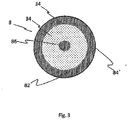
- a detachment level 8 is shown, the areas with different defect concentrations 82, 84, 86 has. It is conceivable that a plurality of regions with different defect concentrations form a release plane 8, wherein it is also conceivable that the defects 34 in the release plane 8 are distributed substantially or exactly uniformly over the surface.
- the different defect concentrations can be of the same size or different in size.
- a first increased defect concentration represents a crack initiation concentration 82, which is preferably generated in the region of the edge or extending to the edge or adjacent to the edge.
- a crack guidance concentration 84 may be formed such that the crack separating the solid-state layer 4 from the solid 2 can be controlled or controlled.
- a center concentration 86 can be generated, which preferably allows a very flat surface in the region of the center of the solid 2.
- the crack guide concentration 84 is partially or completely annular or enclosing and thus preferably encloses sections and more preferably completely the center of the solid 2 and the solid layer 4. It is also conceivable that the crack guidance concentration 84 in a starting from the edge of the solid second and gradually decreases in the direction of the center of the solid 2 or continuously or fluently. Furthermore, it is conceivable. the crack guidance concentration 84 is formed in a ribbon-like and homogeneous or substantially or exactly homogeneous manner.
Abstract
Die Erfindung betrifft ein Polymer-Hybrid-Material für ein Splitting-Verfahren zur Teilung eines Festkörper-Ausgangsmaterial in zumindest zwei Festkörper-Teilstücke, ein Verfahren zur Herstellung eines solchen Polymer-Hybrid-Materials, die Verwendung des Polymer-Hybrid-Materials in einem Splitting-Verfahren sowie ein Splitting-Verfahren. Das Polymer-Hybrid-Material enthält eine Polymermatrix, die eine Elastomermatrix ist und einen oder mehrere Füllstoffe enthält. Zur Herstellung des Polymer-Hybrid-Materials werden einer Elastomermatrix als einer Polymermatrix ein oder mehrere Füllstoffe zugefügt.The invention relates to a polymer hybrid material for a splitting process for dividing a solid starting material into at least two solid sections, a method for producing such a polymer hybrid material, the use of the polymer hybrid material in a splitting Method and a splitting method. The polymer hybrid material contains a polymer matrix which is an elastomer matrix and contains one or more fillers. To prepare the polymer hybrid material, one or more fillers are added to an elastomer matrix as a polymer matrix.
Ein Splitting-Verfahren umfasst die Schritte des Bereitstellens des Festkörper-Ausgangsmaterials mit zumindest einer freiliegenden Oberfläche, des Aufbringens eines Polymer-Hybrid-Materials, welches einen oder mehrere Füllstoffe in einer Polymermatrix enthält, auf zumindest eine freiliegende Oberfläche des Festkörper-Ausgangsmaterial, so dass eine Verbundstruktur resultiert und die Beaufschlagung der Verbundstruktur mit einem Spannungsfeld derart, dass das Festkörper-Ausgangsmaterial entlang einer Ebene innerhalb des Festkörper-Ausgangsmaterials in zumindest zwei Festkörper-Teilstücke gespalten wird. Einer der Füllstoffe besteht aus zumindest einem Metall und bewirkt eine verbesserte Wärmeleitfähigkeit innerhalb des Polymer-Hybrid-Materials.

Description
Die Erfindung betrifft ein Polymer-Hybrid-Material für ein Splitting-Verfahren zur Teilung eines Festkörper-Ausgangsmaterial in zumindest zwei Festkörper-Teilstücke, ein Verfahren zur Herstellung eines solchen Polymer-Hybrid-Materials, die Verwendung des Polymer-Hybrid-Materials in einem Splitting-Verfahren sowie ein Splitting-Verfahren.The invention relates to a polymer hybrid material for a splitting process for dividing a solid starting material into at least two solid sections, a method for producing such a polymer hybrid material, the use of the polymer hybrid material in a splitting Method and a splitting method.
Vor allem in der Mikroelektronik und Photovoltaik werden Wafer, d. h. dünne Scheiben oder Platten, aus Materialien wie Silizium, Germanium oder Saphir eingesetzt. Diese werden derzeit üblicherweise aus einem säulen- oder blockförmigen Festkörper, welcher auch als Ingot bezeichnet wird, gewonnen.Especially in microelectronics and photovoltaics wafers, d. H. thin discs or plates, made of materials such as silicon, germanium or sapphire. These are currently usually obtained from a columnar or block-shaped solid, which is also referred to as ingot.
Aus derartigen Ingots werden beispielsweise mittels eines Säge- oder Zerreißverfahrens zylinder- oder scheibenförmige Teilstücke erzeugt. Diese Teilstücke können bereits einen Wafer repräsentieren oder die erhaltenen Teilstücke werden weiter unterteilt, bis diese die gewünschte Dicke eines herzustellenden Wafers aufweisen.From such ingots, for example, by means of a sawing or tearing process, cylinder-shaped or disk-shaped sections are produced. These sections may already represent a wafer or the resulting sections are further subdivided until they have the desired thickness of a wafer to be produced.
Bei dem Säge- oder Zerreißverfahren werden zumeist Draht- oder Diamantdrahtsägen eingesetzt, wodurch ein Teil von bis zu 50 % des ursprünglichen Festkörpers in Form von Spänen als sog. "kerf-loss" verloren geht, was insbesondere bei teuren Ausgangsmaterialien nachteilig ist.Wire or diamond wire saws are usually used in the sawing or tearing process, whereby a part of up to 50% of the original solid in the form of chips is lost as so-called "kerf loss", which is disadvantageous especially with expensive starting materials.
Zudem beschädigt der Sägevorgang häufig die Waferoberfläche, welche mittels zusätzlicher Prozessschritte zur Oberflächenbehandlung, wie beispielsweise Läpp- oder Polierverfahrensschritten, beseitigt werden müssen.In addition, the sawing process often damages the wafer surface, which must be eliminated by means of additional process steps for surface treatment, such as lapping or polishing process steps.
Zur Vermeidung der genannten Nachteile ist beispielsweise aus der
Das beschriebene Verfahren, nachfolgend als "Splitting-Verfahren" bezeichnet, kann auch zur Spaltung eines dicken Wafers in zwei dünne Wafer genutzt werden, indem auf beide gegenüberliegende Seiten des dicken Wafers Polymerfolien aufgeklebt werden und dieser durch eine entsprechende thermische Behandlung in zwei dünne Wafer aufgespalten wird.The described method, hereinafter referred to as "splitting method", can also be used for splitting a thick wafer into two thin wafers by adhering polymer foils to both opposite sides of the thick wafer and splitting the same into two thin wafers by a corresponding thermal treatment becomes.
Die Effektivität eines solchen Verfahrens ist insbesondere von der Auswahl eines Polymers mit einer geeigneten Glasübergangstemperatur (Tg), der Wärmeleitfähigkeit des Polymers sowie dessen mechanischen Eigenschaften wie Sprödigkeit, Zugfestigkeit und Elastizität abhängig.The effectiveness of such a process depends in particular on the choice of a polymer with a suitable glass transition temperature (T g ), the thermal conductivity of the polymer and its mechanical properties such as brittleness, tensile strength and elasticity.
Weiterhin ist in der
Nachteilig an diesem Verfahren ist jedoch die lange Zeitdauer, welche bis zu mehreren Stunden bestragen kann, die bis zu einer vollständigen Entfernung der Polymerschicht vergeht. Dies schränkt eine industrielle Nutzung stark ein.A disadvantage of this method, however, is the long period of time, which can last up to several hours, which elapses until complete removal of the polymer layer. This severely restricts industrial use.
Zur Beschleunigung des Prozesses der Polymerentfernung besteht die Möglichkeit, durch eine entsprechende Vorbehandlung zusätzliche Triebkräfte in Form von geeigneten, auch bei Raumtemperatur wirkenden Zugspannungen einzubringen. Diese führen zu einer Vergrößerung der Angriffsfläche für die Reaktanden bzw. das Lösungsmittel und begünstigen das Zersetzen bzw. das Ab- und Auflösen. Durch die eingebrachten zusätzlichen Spannungen kann es jedoch auch nach der Entfernung des Polymers zu einer Beschädigung des gespaltenen Festkörpers, also z. B. des Wafers, kommen, indem dieser beispielsweise bricht. Damit verbunden ist eine Verschlechterung der Gesamtausbeute, welche den Kostenvorteil des Splitting-Verfahrens verringert.To speed up the process of polymer removal it is possible to introduce additional driving forces in the form of suitable tensile stresses, which also act at room temperature, by means of a corresponding pretreatment. These lead to an increase in the attack surface for the reactants or the solvent and promote decomposition or dissolution and dissolution. Due to the introduced additional stresses, however, it may also after the removal of the polymer to damage the cleaved solid, so z. As the wafer, come by this breaks, for example. This is associated with a deterioration of the overall yield, which reduces the cost advantage of the splitting method.
Aufgabe der Erfindung ist es, eine Möglichkeit zur Erhöhung der Gesamtausbeute, d. h. der Effizienz in Bezug auf die eingesetzten Rohmaterialien und die anderweitigen Ressourcen wie Energie und Arbeitskraft, eines Splitting-Verfahrens anzugeben.The object of the invention is to provide a way to increase the overall yield, d. H. the efficiency in terms of raw materials used and other resources, such as energy and labor, of a splitting process.
Bevorzugt soll der zeitliche Verlauf der Polymerentfernung nach einem Splitting-Verfahren gezielt beeinflusst werden.Preferably, the time course of the polymer removal should be influenced in a targeted manner by a splitting method.
Bevorzugt soll das Polymer schnell, rückstandsfrei und ohne Beschädigung des geteilten Ausgangsmaterials von diesem abtrennbar sein.Preferably, the polymer should be quickly, residue-free and without damage to the divided starting material of this separable.
Vorteilhaft soll das Polymer wiederverwendbar sein.Advantageously, the polymer should be reusable.
Zudem soll die Prozessstabilität durch eine Minimierung der Anzahl an Verfahrensschritten erhöht werden.In addition, the process stability should be increased by minimizing the number of process steps.
Die erfindungsgemäße Lösung dieser Aufgabe erfolgt gemäß den Merkmalen der unabhängigen Ansprüche. Die abhängigen Ansprüche geben vorteilhafte Ausführungsvarianten der erfindungsgemäßen Lösung wider.The inventive solution of this object is achieved according to the features of the independent claims. The dependent claims reflect advantageous embodiments of the inventive solution.
Untersuchungen zeigten, dass es sich bei der Entfernung der Polymerschicht durch Zersetzung, Ab- oder Auflösung um eine diffusionskontrollierte Reaktion der beteiligten Reaktanden bzw. Lösungsmittel handelt. Mit fortschreitendem Zeitverlauf wird der Zu- und Abtransport der Reaktanden im sich ausbildenden Spalt zwischen Festkörper und Polymer immer mehr erschwert und sehr stark verlangsamt. Somit ist der An- und Abtransport der Reaktionsprodukte und -edukte bzw. des Lösungsmittels und der gelösten Bestandteile der diffusionskontrollierte geschwindigkeitsbestimmende Schritt.Investigations showed that the removal of the Polymer layer by decomposition, dissolution or dissolution by a diffusion-controlled reaction of the reactants or solvents involved. As the time progresses, the supply and removal of the reactants in the forming gap between solid and polymer becomes increasingly more difficult and very much slowed down. Thus, the supply and removal of the reaction products and educts or the solvent and the dissolved constituents of the diffusion-controlled rate-determining step.
Erfindungsgemäß wird in einem Splitting-Verfahren, bei welchem aus einem Festkörper-Ausgangsmaterial zumindest zwei Festkörper-Teilstücke erzeugt werden, ein Polymer-Hybrid-Material verwendet.According to the invention, a polymer hybrid material is used in a splitting method, in which at least two solid sections are produced from a solid starting material.
Insbesondere kann das Polymer-Hybrid-Material in einem Splitting-Verfahren verwendet werden, bei dem aus einem zylinderförmigen Festkörper-Ausgangsmaterial mehrere zylinderförmige, bevorzugt scheibenförmige, Festkörper-Teilstücke, insbesondere Wafer, erzeugt werden.In particular, the polymer hybrid material can be used in a splitting method in which a plurality of cylindrical, preferably disk-shaped, solid body sections, in particular wafers, are produced from a cylindrical solid state starting material.
Unter Zylinder ist dabei ein von zwei parallelen, ebenen, kongruenten Flächen (Grund- und Deckfläche) und einer Mantel- bzw. Zylinderfläche begrenzter Körper zu verstehen, wobei die Mantelfläche von parallelen Geraden gebildet wird. Bevorzugt sind Grund- und Deckfläche kreisförmig ausgebildet und liegen deckungsgleich übereinander, so dass ein gerader Kreiszylinder resultiert. Gleichwohl sind auch andere Zylindergestaltungen, z. B. mit n-eckigen Grundflächen mit n = 3, 4, 5 oder 6, denkbar, wobei Grund- und Deckfläche bevorzugt deckungsgleich übereinander liegen.Under cylinder is to be understood by one of two parallel, flat, congruent surfaces (top and top surface) and a shell or cylindrical surface of limited body, wherein the lateral surface is formed by parallel straight lines. Preferably, the base and top surfaces are circular and lie congruently one above the other, so that a straight circular cylinder results. Nevertheless, other cylinder designs, eg. B. with n-sided base areas with n = 3, 4, 5 or 6, conceivable, with the base and top surfaces preferably above one another congruent.
Gemäß der vorliegenden Beschreibung wird unter einem Festkörper-Ausgangsmaterial ein monokristallines, polykristallines oder amorphes Material verstanden. Bevorzugt eignen sich wegen der stark anisotropen atomaren Bindungskräfte Monokristalline mit einer stark anisotropen Struktur. Das Festkörper-Ausgangsmaterial weist bevorzugt ein Material oder eine Materialkombination aus einer der Hauptgruppen 3, 4, 5 und/oder 12 des Periodensystems der Elemente, insbesondere eine Kombination aus Elementen der 3., 5. und der 12. Hauptgruppe, auf.As used herein, a solid state starting material is understood to mean a monocrystalline, polycrystalline or amorphous material. Preferably, they are suitable because of the highly anisotropic atomic Binding forces Monocrystalline with a strongly anisotropic structure. The solid-state starting material preferably comprises a material or a combination of materials from one of the main groups 3, 4, 5 and / or 12 of the Periodic Table of the Elements, in particular a combination of elements of the 3rd, 5th and 12th main group.
Neben Silizium kann das Halbleiter-Ausgangsmaterial beispielsweise auch aus Galliumarsenid GaAs, Galliumnitrid GaN, Siliciumcarbid SiC, Indiumphosphid InP, Zinkoxid ZnO, Aluminiumnitrid AlN, Germanium, Gallium(III)-oxid Ga2O3, Aluminiumoxid Al2O3 (Saphir), Galliumphosphid GaP, Indiumarsenid InAs, Indiumnitrid InN, Aluminiumarsenid AlAs oder Diamant bestehen.In addition to silicon, the semiconductor starting material can also be composed, for example, of gallium arsenide GaAs, gallium nitride GaN, silicon carbide SiC, indium phosphide InP, zinc oxide ZnO, aluminum nitride AlN, germanium, gallium (III) oxide Ga 2 O 3 , aluminum oxide Al 2 O 3 (sapphire), Gallium phosphide GaP, indium arsenide InAs, indium nitride InN, aluminum arsenide AlAs or diamond.
Der Festkörper bzw. das Werkstück weist bevorzugt ein Material oder eine Materialkombination aus einer der Hauptgruppen 3, 4 und 5 des Periodensystems der Elemente auf, wie z.B. Si, SiC, SiGe, Ge, GaAs, InP, GaN, Al2O3 (Saphir), AlN. Besonders bevorzugt weist der Festkörper eine Kombination aus in der dritten und fünften Gruppe des Periodensystems vorkommenden Elementen auf. Denkbare Materialien oder Materialkombinationen sind dabei z.B. Galliumarsenid, Silizium, Siliziumcarbid, etc. Weiterhin kann der Festkörper eine Keramik (z.B. Al203 - Alumiumoxid) aufweisen oder aus einer Keramik bestehen, bevorzugte Keramiken sind dabei z.B. Perovskitkeramiken (wie z.B. Pb-, O-, Ti/Zr-haltige Keramiken) im Allgemeinen und Blei-Magnesium-Niobate, Bariumtitanat, Lithiumtitanat, Yttrium-Aluminium-Granat, insbesondere Yttrium-Aluminium-Granat Kristalle für Festkörperlaseranwendungen, SAW-Keramiken (surface acoustic wave), wie z.B. Lithiumniobat, Galliumorthophosphat, Quartz, Calziumtitanat, etc. im Speziellen. Der Festkörper weist somit bevorzugt ein Halbleitermaterial oder ein Keramikmaterial auf bzw. besonders bevorzugt besteht der Festkörper aus mindestens einem Halbleitermaterial oder einem Keramikmaterial. Es ist weiterhin denkbar, dass der Festkörper ein transparentes Material aufweist oder teilweise aus einem transparenten Material, wie z.B. Saphir, besteht bzw. gefertigt ist. Weitere Materialien, die hierbei als Festkörpermaterial alleine oder in Kombination mit einem anderen Material in Frage kommen, sind z.B. "wide band gap"-Materialien, InAlSb, Hochtemperatursupraleiter, insbesondere seltene Erden Cuprate (z.B. YBa2Cu307). Es ist zusätzlich oder alternativ denkbar, dass der Festkörper eine Photomaske ist, wobei als Photomaskenmaterial im vorliegenden Fall bevorzugt jedes zum Anmeldetag bekannte Photomaskenmaterial und besonders bevorzugt Kombinationen daraus verwendet werden können.The solid or the workpiece preferably comprises a material or a combination of materials from one of the main groups 3, 4 and 5 of the Periodic Table of the Elements, such as Si, SiC, SiGe, Ge, GaAs, InP, GaN, Al2O3 (sapphire), AlN , Particularly preferably, the solid has a combination of elements occurring in the third and fifth group of the periodic table. Conceivable materials or combinations of materials are eg gallium arsenide, silicon, silicon carbide, etc. Furthermore, the solid may have a ceramic (eg Al203 - alumina) or consist of a ceramic, preferred ceramics are eg Perovskitkeramiken (such as Pb-, O-, Ti / Zr-containing ceramics) in general and lead magnesium niobates, barium titanate, lithium titanate, yttrium aluminum garnet, in particular yttrium aluminum garnet crystals for solid-state laser applications, surface acoustic wave (SAW) ceramics such as lithium niobate, gallium orthophosphate, Quartz, calcium titanate, etc. in particular. The solid body thus preferably has a semiconductor material or a ceramic material or Particularly preferably, the solid body consists of at least one semiconductor material or a ceramic material. It is also conceivable that the solid body has a transparent material or partially made of a transparent material, such as sapphire, or is made. Further materials that may be used here as solid material alone or in combination with another material are, for example, "wide band gap" materials, InAlSb, high-temperature superconductors, in particular rare earth cuprates (eg YBa2Cu307). It is additionally or alternatively conceivable that the solid body is a photomask, wherein as photomask material in the present case, preferably any known to the filing date photomask material and more preferably combinations thereof can be used.
Unter einem Polymer-Hybrid-Material ist erfindungsgemäß ein Material zu verstehen, welches einen oder mehrere Füllstoffe in einer Polymermatrix enthält. Insofern im Folgenden von einem bzw. dem Füllstoff die Rede ist, soll gleichfalls die Möglichkeit mehrerer Füllstoffe mit einbezogen sein.According to the invention, a polymer hybrid material is to be understood as meaning a material which contains one or more fillers in a polymer matrix. Insofar as in the following of one or the filler is mentioned, should also be included the possibility of multiple fillers.
Als Polymermatrix kann jedes Polymer genutzt werden, mit dessen Hilfe sich die für eine Teilung des Festkörper-Ausgangsmaterials notwendigen Spannungen erzeugen lassen. Beispielsweise kann die Polymermatrix als Elastomermatrix, bevorzugt als Polydiorganolsiloxan-Matrix, besonders bevorzugt als Polydimethylsiloxan-Matrix, ausgebildet sein. Derartige Polymermaterialien lassen sich besonders einfach als Matrixmaterial in Kombination mit Füllstoffen nutzen, da die Eigenschaften aufgrund des variierbaren Vernetzungsgrads flexibel eingestellt und an den jeweiligen Füllstoff sowie das zu teilende Festkörper-Ausgangsmaterial angepasst werden können.As the polymer matrix, any polymer can be used, with the help of which can generate the necessary voltages for a division of the solid state starting material. For example, the polymer matrix may be formed as an elastomer matrix, preferably as a polydiorganosiloxane matrix, particularly preferably as a polydimethylsiloxane matrix. Such polymer materials are particularly easy to use as a matrix material in combination with fillers, since the properties can be flexibly adjusted due to the variable degree of crosslinking and adapted to the respective filler and the solid-state starting material to be divided.
Die Verwendung eines Polymer-Hybrid-Materials schließt auch ein, dass verschiedene Polymere mit einem oder mehreren gleichen oder unterschiedlichen Füllstoffen genutzt werden, welche zusammen das Polymer-Hybrid-Material bilden.The use of a polymer hybrid material also includes that various polymers having one or more same or different fillers are used, which together form the polymer hybrid material.
Der Füllstoff kann organischer oder anorganischer Natur sein und sowohl aus einem chemischen Element als auch aus einer chemischen Verbindung oder einem Stoffgemisch, beispielsweise einer Legierung, bestehen. Er liegt in partikulärer Form in der Polymermatrix verteilt vor, wobei die Partikelgröße üblicherweise im pm- und nm-Bereich, bezogen auf zumindest eine Dimension des Partikels, liegt. Neben einer kugelförmigen Gestalt können die Füllstoffpartikel auch andere Ausgestaltungen, beispielsweise eine stäbchenförmige oder scheibenförmige Gestalt annehmen.The filler may be of organic or inorganic nature and consist of both a chemical element and a chemical compound or a mixture of substances, for example an alloy. It is present in particulate form distributed in the polymer matrix, wherein the particle size is usually in the pm and nm range, based on at least one dimension of the particle. In addition to a spherical shape, the filler particles can also assume other configurations, for example a rod-shaped or disc-shaped form.
Die Füllstoffpartikel können sämtliche Partikelgrößenverteilungen aufweisen, beispielsweise monomodal oder bimodal, eng, insbesondere monodispers, oder breit. Der Füllstoff kann an die Polymermatrix sowohl physikalisch, z. B. durch Einbettung in das Polymernetzwerk, als auch chemisch angebunden sein.The filler particles can have all particle size distributions, for example monomodal or bimodal, narrow, in particular monodisperse, or broad. The filler can be attached to the polymer matrix both physically, e.g. B. by embedding in the polymer network, as well as be chemically attached.
Der konkrete Füllstoffanteil in der Polymermatrix ist stark vom Material des Füllstoffs und dessen Wirkungsweise abhängig. Zum einen muss die Polymermatrix trotz Füllstoff ihrer Aufgabe der Erzeugung von Spannungen noch gerecht werden können. Zum anderen muss der Füllstoffanteil hoch genug sein, um die angestrebte Beeinflussung der Polymerentfernung zu erreichen. Den jeweils optimalen Füllstoffanteil kann der Fachmann im Rahmen einfacher konzentrationsabhängig durchgeführter Versuche ermitteln.The concrete filler content in the polymer matrix is highly dependent on the material of the filler and its mode of action. On the one hand, despite its filler, the polymer matrix must be able to do justice to its task of generating stresses. On the other hand, the filler must be high enough to achieve the desired effect on the polymer removal. The optimum filler content in each case can be determined by the person skilled in the art within the scope of simple experiments carried out in a concentration-dependent manner.
Das Polymer-Hybrid-Material wird in einem Splitting-Verfahren verwendet, indem zunächst das zu teilende Festkörper-Ausgangsmaterial mit einer freiliegenden Oberfläche bereitgestellt wird. Auf diese Oberfläche wird das Polymer-Hybrid-Material aufgebracht, so dass eine entsprechende Verbundstruktur resultiert. Optional kann das Polymer-Hybrid-Material auch auf mehrere freiliegende Oberflächen, insbesondere auf parallel zueinander angeordnete Oberflächen aufgebracht werden.The polymer hybrid material is used in a splitting process by first providing the solid state starting material to be separated with an exposed surface. On this surface will be applied the polymer hybrid material, so that a corresponding composite structure results. Optionally, the polymer-hybrid material can also be applied to a plurality of exposed surfaces, in particular to surfaces arranged parallel to one another.
Insbesondere kann es sich um ein zylinderförmiges Festkörper-Ausgangsmaterial handeln. In diesem Fall wird das Polymer-Hybrid-Material auf eine freiliegende Grund- und/oder Deckfläche aufgebracht.In particular, it may be a cylindrical solid-state starting material. In this case, the polymer-hybrid material is applied to an exposed base and / or top surface.
Dies kann beispielsweise durch Aufkleben einer Folie bestehend aus dem Polymer-Hybrid-Material erfolgen. Alternativ kann auch eine Vorläufersubstanz des Polymer-Hybrid-Materials aus flüssiger Phase auf der freiliegenden Oberfläche des Festkörper-Ausgangsmaterials aufgetragen werden, der sich ein physikalischer und/oder chemischer Vorgang, beispielsweise Verdunstung und/oder Vernetzungsreaktionen, zur Ausbildung des eigentlichen Polymer-Hybrid-Material anschließt.This can be done for example by sticking a film consisting of the polymer-hybrid material. Alternatively, a precursor substance of the liquid phase polymer hybrid material can also be applied to the exposed surface of the solid starting material which undergoes a physical and / or chemical process, such as evaporation and / or crosslinking, to form the actual polymer hybrid. Material connects.
Darauffolgend wird die Verbundstruktur mit einem Spannungsfeld derart beaufschlagt, dass das Festkörper-Ausgangsmaterial entlang einer Ebene innerhalb des Festkörper-Ausgangsmaterials in zumindest zwei Festkörper-Teilstücke gespalten wird. Das Spannungsfeld kann beispielsweise durch plötzliches Abkühlen oder Erwärmen, insbesondere durch plötzliches Abkühlen mittels flüssigen Stickstoffs, erfolgen, wobei das Spannungsfeld aufgrund der unterschiedlichen Wärmeausdehnungskoeffizienten des Festkörper-Ausgangsmaterials und des Polymer-Hybrid-Materials sowie der resultierenden signifikanten Änderung des E-Moduls entsteht.Subsequently, the composite structure is subjected to a voltage field such that the solid state starting material is split along a plane within the solid state starting material into at least two solid sections. The stress field can be, for example, by sudden cooling or heating, in particular by sudden cooling by means of liquid nitrogen, wherein the stress field arises due to the different thermal expansion coefficients of the solid state starting material and the polymer hybrid material and the resulting significant change in the modulus of elasticity.
Zur Weiterverwendung der Festkörper-Teilstücke wird das Polymer-Hybrid-Material beispielsweise durch eine chemische Reaktion, ein physikalischen Ablösevorgang und/oder mechanisches Abtragen entfernt.For further use of the solid sections, the polymer-hybrid material, for example, by a chemical Reaction, removed a physical detachment process and / or mechanical removal.
Optional kann zwischen dem Festköper-Ausgangsmaterial und dem Polymer-Hybrid-Material eine Opferschicht vorgesehen sein, die das Entfernen des Polymer-Hybrid-Materials nach erfolgter Teilung vereinfacht, indem beispielsweise die Opferschicht durch eine geeignete chemische Reaktion zersetzt wird.Optionally, a sacrificial layer may be provided between the solid state starting material and the polymer hybrid material to facilitate removal of the polymer hybrid material after division, for example, by decomposing the sacrificial layer by a suitable chemical reaction.
Während die Polymermatrix der Generierung der zur Teilung des Festkörper-Ausgangsmaterials notwendigen Spannungen dient, ist die primäre Aufgabe des Füllstoffs eine gezielte Beeinflussung der Polymerentfernung nach der Teilung des Festkörper-Ausgangsmaterials zu bewirken. Dazu kann der Füllstoff beispielsweise als Katalysator, Promotor, Initiator, aber auch als Inhibitor wirken. Neben dem Ablöseverhalten können auch die thermischen und/oder mechanischen Eigenschaften beeinflusst werden.While the polymer matrix serves to generate the stresses necessary to divide the solid state starting material, the primary function of the filler is to effectuate targeted polymer removal after the solid state starting material has been partitioned. For this purpose, the filler may act, for example, as a catalyst, promoter, initiator, but also as an inhibitor. In addition to the detachment behavior, the thermal and / or mechanical properties can also be influenced.
Insbesondere kann durch die Verwendung eines Füllstoffs die Polymerentfernung beschleunigt werden, indem der An- und Abtransport des Lösungsmittels und der gelösten Bestandteile bzw. der Reaktionsedukte und -produkte verbessert wird. Dadurch können die nach dem Stand der Technik bisher erforderlichen zusätzlichen Spannungen bis hin zu einem kompletten Verzicht reduziert werden, so dass dadurch verursachte Beschädigungen der Festkörper-Teilstücke vermieden werden können. Im Ergebnis resultieren eine verkürzte Prozesszeit und eine verbesserte Gesamtausbeute.In particular, the use of a filler can accelerate polymer removal by improving the delivery and removal of the solvent and solutes or reaction products and products. As a result, the previously required according to the prior art additional voltages can be reduced to a complete waiver, so that caused damage to the solid sections can be avoided. The result is a shorter process time and an improved overall yield.
Zudem wird die Prozessstabilität des Gesamtverfahrens erhöht, da aufgrund des möglichen Verzichts auf das Einbringen zusätzlicher Spannungen weniger Prozessschritte notwendig sind.In addition, the process stability of the overall process is increased, since fewer process steps are necessary due to the possible omission of the introduction of additional voltages.
Unterliegen die Polymermatrix und/oder die Füllstoffe keiner chemischen Reaktion, so ist zudem deren Wiederverwendung möglich.Are the polymer matrix and / or the fillers none chemical reaction, their reuse is also possible.
Besonders bevorzugt wird die Entfernung des Polymer-Hybrid-Materials derart beschleunigt, dass auf eine zusätzliche Opferschicht verzichtet werden kann. Dies trägt zu einer weiteren Vereinfachung und damit zur Erhöhung der Prozessstabilität des Splitting-Verfahrens bei.Particularly preferably, the removal of the polymer hybrid material is accelerated in such a way that it is possible to dispense with an additional sacrificial layer. This contributes to a further simplification and thus to an increase in the process stability of the splitting method.
Gemäß einer Ausführungsvariante besteht ein Füllstoff aus zumindest einem Metall, insbesondere aus Aluminium, Eisen, Zink und/oder Kupfer.According to one embodiment, a filler consists of at least one metal, in particular aluminum, iron, zinc and / or copper.
"Bestehend aus" schließt auf alle vorliegend genannten Materialien bezogen ein, dass technologisch bedingte Verunreinigungen oder technologisch bedingte Beimengungen, die z. B. der Herstellung der Füllstoffe sowie deren Verteilung oder Anbindung an die Polymermatrix dienlich sind, enthalten sein können."Consisting of" includes all materials referred to above, that technologically caused impurities or technologically caused admixtures, the z. B. the preparation of the fillers and their distribution or attachment to the polymer matrix are useful, may be included.
Metallische Füllstoffe können mit Oxidationsmitteln wie z. B. Salzsäure, Salpetersäure, Zitronensäure, Ameisensäure oder Sulfaminsäure reagieren und dadurch aus dem Polymer-Hybrid-Material entfernt werden. Beispielsweise reagiert Aluminium mit konzentrierter Salzsäure unter Ausbildung von solvatisierten Metallionen und Wasserstoff gemäß folgender Gleichung:
6 HCl + 2 Al + 12 H2O → 2 [AlCl3*6 H2O] + 3 H2
Metallic fillers can with oxidizing agents such as. For example, hydrochloric acid, nitric acid, citric acid, formic acid or sulfamic acid and thereby be removed from the polymer-hybrid material. For example, aluminum reacts with concentrated hydrochloric acid to form solvated metal ions and hydrogen according to the following equation:
6HCl + 2Al + 12H 2 O → 2 [AlCl 3 * 6H 2 O] + 3H 2
Die dadurch in der Polymermatrix entstehenden Kavitäten ermöglichen einen schnelleren Zugang der Reaktanden bzw. Lösungsmittel zur Polymer- bzw. Opferschicht und bewirken zudem einen schnelleren Abtransport der Edukte bzw. gelösten Bestandteile.The resulting in the polymer matrix cavities allow faster access of the reactants or solvents to the polymer or sacrificial layer and also cause a faster removal of the educts or dissolved constituents.
In ähnlicher Weise führt die Reaktion von Zink als Füllstoff durch Reaktion mit konzentrierter Salzsäure zur Bildung zusätzlicher Kavitäten:
Zn + 2 HCl → ZnCl2 + H2
Similarly, the reaction results in zinc as a filler by reaction with concentrated hydrochloric acid to form additional cavities:
Zn + 2 HCl → ZnCl 2 + H 2
Zudem werden durch die Generierung gasförmiger Reaktionsprodukte, in den genannten Beispielen durch die Generierung von Wasserstoff, zusätzliche Triebkräfte eingebracht, die die Entfernung des Polymer-Hybrid-Materials weiter unterstützen.In addition, by the generation of gaseous reaction products, in the examples mentioned by the generation of hydrogen, additional driving forces are introduced, which further support the removal of the polymer-hybrid material.
Die Ausbildung zusätzlicher Kavitäten sowie das Entstehen gasförmiger Reaktionsprodukte beschleunigt die Polymerentfernung und trägt daher zu einer Erhöhung der Gesamtausbeute des Splitting-Verfahrens bei. Durch Variation der Füllstoffkonzentration kann die Kavitätendichte im Grenzbereich zwischen Festkörper-Teilstück und Polymer-Hybrid-Material bzw. zwischen Opferschicht und Polymer-Hybrid-Material gezielt beeinflusst werden.The formation of additional cavities and the formation of gaseous reaction products accelerate the polymer removal and therefore contributes to an increase in the overall yield of the splitting process. By varying the filler concentration, the cavity density can be selectively influenced in the boundary region between the solid body section and the polymer hybrid material or between the sacrificial layer and the polymer hybrid material.
Ein weiterer Vorteil für den Fall, dass der Füllstoff aus Metall besteht, liegt in der verbesserten Wärmeleitfähigkeit innerhalb des Polymer-Hybrid-Materials. Dadurch sind die für die Teilung des Festkörper-Ausgangsmaterials mittels Abkühlung erzeugten Spannungen effektiver, d. h. schneller und unter geringerem Verbrauch an Kühlmittel, generierbar. Dies erhöht die Gesamtausbeute des Splitting-Verfahrens.Another advantage in the case where the filler is metal is the improved thermal conductivity within the polymer hybrid material. As a result, the voltages generated by the cooling for the division of the solid state starting material are more effective, i. H. faster and with lower consumption of coolant, can be generated. This increases the overall yield of the splitting method.
Gemäß einer Ausführungsvariante kann ein Füllstoff aus anorganischen Fasern, wie beispielsweise Kohle-, Glas- oder Basaltfasern bestehen.According to one embodiment, a filler may consist of inorganic fibers, such as carbon, glass or basalt fibers.
Fasern weisen üblicherweise stark anisotrope Eigenschaften auf. Durch eine richtungsabhängige Positionierung des Füllstoffs im Polymer-Hybrid-Material besteht die Möglichkeit einer gezielten Beeinflussung der für die Teilung des Festkörper-Ausgangsmaterials notwendigen Spannungen. Dies kann zur Erhöhung der Gesamtausbeute des Splitting-Verfahrens beitragen.Fibers usually have strongly anisotropic properties. By a direction-dependent positioning of the filler in the polymer-hybrid material there is the possibility of a targeted influencing necessary for the division of the solid starting material Tensions. This can help increase the overall yield of the splitting process.
Ein zusätzlicher Vorteil besteht in dem Falle, dass ein organischer oder anorganischer Füllstoff als Faserstoff mit einer stark anisotropen Struktur eingesetzt wird, darin, dass dadurch eine Verbesserung der mechanischen Eigenschaften innerhalb des Polymer-Hybrid-Materials erreicht werden kann.An additional advantage, in the case where an organic or inorganic filler is used as a pulp having a highly anisotropic structure, is that it can achieve an improvement in mechanical properties within the polymer hybrid material.
Gemäß eine weiteren Ausführungsvariante besteht ein Füllstoff aus Kern-Schale-Partikeln oder Kieselsäure. Kern-Schale-Partikel zeichnen sich dadurch aus, dass ein in der Regel kugelförmiger Kern aus einem Material von einer Schale aus einem zweiten Material umgeben ist. Die Schale kann entweder den Kern komplett umhüllen oder aber auch durchlässig sein.According to a further embodiment variant, a filler consists of core-shell particles or silica. Core-shell particles are characterized by the fact that a generally spherical core of a material is surrounded by a shell of a second material. The shell can either completely encase the core or be permeable.
Bei den Materialien kann es sich sowohl um anorganische Materialien, wie z. B. Metalle, oder um organische Materialien, wie z. B. Polymere handeln. Beispielsweise können zwei verschiedene Metalle miteinander kombiniert werden. Es besteht aber auch die Möglichkeit, einen Kern aus einem Polymer mit einer Schale aus einem Metall oder einem zweiten Polymer zu umgeben.The materials may be both inorganic materials, such as. As metals, or organic materials such. As polymers act. For example, two different metals can be combined with each other. But it is also possible to surround a core of a polymer with a shell of a metal or a second polymer.
Kern-Schale-Partikel ermöglichen die Kombination der Eigenschaften des ersten und zweiten Materials. Beispielsweise kann über einen preiswerten Polymerkern die Größe und Dichte der Füllstoffpartikel festgelegt werden, während die metallische Schale wie oben beschrieben reagieren kann. Aufgrund ihrer oftmals monodispersen Partikelgrößenverteilung lassen sich die Eigenschaften der Kern-Schale-Partikel zudem präzise vorhersagen und einstellen.Core-shell particles allow the combination of the properties of the first and second materials. For example, the size and density of the filler particles can be determined via a low-cost polymer core, while the metallic shell can react as described above. Due to their often monodisperse particle size distribution, the properties of the core-shell particles can also be accurately predicted and adjusted.
Zur Verbesserung der mechanischen Eigenschaften kann ebenfalls ein zusätzlich einzubringender Füllstoff, wie z.B. pyrogene Kieselsäure in Form eines anorganischen Netzwerkes im Polymer beitragen. Neben diesen starken Wechselwirkungen können auch weniger starke Interaktionen durch rein hydrodynamische Verstärkungen zur Verbesserung beitragen. Beispielhaft ist hier eine gezielte Steigerung der Viskosität zu nennen, die eine verbesserte Verarbeitung im Splitverhalten ermöglicht und so zu verbesserten Fertigungstoleranzen beitragen kann. Weiterhin wird durch diese Wechselwirkung eine Verringerung der inneren Freiheitsgrade hinsichtlich einer strukturellen Umorientierung mit zunehmender Bewehrung erschwert. Dies führt zu einer gewünschten Erniedrigung der Glasübergangstemperatur des eingesetzten Polymers im Polymer-Hybrid-Material, was den Vorteil einer geringeren Splittemperatur ermöglicht.To improve the mechanical properties can also contribute an additional filler to contribute, such as fumed silica in the form of an inorganic network in the polymer. In addition to these strong interactions, less strong interactions can contribute to the improvement through purely hydrodynamic enhancements. By way of example, a targeted increase in viscosity should be mentioned, which enables improved processing in the split behavior and thus can contribute to improved manufacturing tolerances. Furthermore, this interaction makes it difficult to reduce the internal degrees of freedom with regard to structural reorientation with increasing reinforcement. This leads to a desired lowering of the glass transition temperature of the polymer used in the polymer hybrid material, which allows the advantage of a lower chip temperature.
Der Füllstoff kann in der Polymermatrix so verteilt sein, dass das Polymer-Hybrid-Material isotrope oder anisotrope Eigenschaften aufweist.The filler may be distributed in the polymer matrix such that the polymer hybrid material has isotropic or anisotropic properties.
Anisotrope Eigenschaften können beispielsweise durch anisotrope Füllstoffeigenschaften oder durch eine gezielte Variation der Füllstoffkonzentration innerhalb der Polymermatrix erreicht werden. Beispielsweise lässt sich durch eine Erhöhung der Füllstoffkonzentration im Grenzbereich zum Festkörper-Ausgangsmaterials bzw. zur Opferschicht die Anzahl der Kavitäten gezielt erhöhen und damit die Entfernung des Polymers beschleunigen. Eine inhomogene Partikeldichteverteilung mit einem in der Schicht senkrechten Gradienten kann zur Verbesserung der mechanischen Eigenschaften, eine homogene Verteilung zur Verbesserung der thermischen Eigenschaften hilfreich sein.Anisotropic properties can be achieved, for example, by anisotropic filler properties or by a targeted variation of the filler concentration within the polymer matrix. For example, an increase in the filler concentration in the boundary region to the solid state starting material or to the sacrificial layer can increase the number of cavities in a targeted manner and thus accelerate the removal of the polymer. An inhomogeneous particle density distribution with a gradient perpendicular to the layer can be helpful for improving the mechanical properties, a homogeneous distribution for improving the thermal properties.
Eine Variation der Füllstoffkonzentration kann zum Beispiel durch die Verwendung von Füllstoffen mit unterschiedlicher Dichte erreicht werden.A variation of the filler concentration can be achieved, for example, by the use of fillers of different types Density can be achieved.
Zur Erzielung von isotropen oder anisotropen Eigenschaften sind stets auch der Vorgang der Herstellung des Polymer-Hybrid-Materials sowie die Eigenschaften der Polymermatrix zu beachten.To achieve isotropic or anisotropic properties, the process of producing the polymer hybrid material and the properties of the polymer matrix must always be taken into account.
Üblicherweise erfolgt die Mischung der Polymermatrix mit dem Füllstoff vor der abschließenden Vernetzung der Polymermatrix. Dies eröffnet die Möglichkeit, die Verteilung des Füllstoffs innerhalb der Polymermatrix in Abhängigkeit der sich durch die Vernetzung verändernden Viskosität der Polymermatrix vorzunehmen.Usually, the mixture of the polymer matrix with the filler takes place before the final crosslinking of the polymer matrix. This opens up the possibility of carrying out the distribution of the filler within the polymer matrix as a function of the viscosity of the polymer matrix which changes as a result of the crosslinking.
Durch eine geeignete Bewegung des Gemischs aus Füllstoff und noch nicht oder nur teilweiser vernetzter Polymermatrix während der abschließenden Vernetzung kann eine gleichmäßige Füllstoffverteilung erreicht werden. Eine langsame Vernetzung ohne Bewirkung führt durch Einwirken der Erdgravitationskraft hingegen aufgrund der Sedimentation zu einer Füllstoffanreicherung im erdnahen Bereich, sofern der Füllstoff eine höhere Dichte als die Polymermatrix aufweist. Dies kann zur Anreicherung des Füllstoffs im Grenzbereich zum Festkörper-Ausgangsmaterials bzw. zur Opferschicht ausgenutzt werden, beispielsweise um dort gezielt durch geeignete Reaktionen Kavitäten zu generieren.By a suitable movement of the mixture of filler and not yet or only partially crosslinked polymer matrix during the final crosslinking, a uniform filler distribution can be achieved. On the other hand, a slow cross-linking without effecting results from the action of the gravitational force due to the sedimentation to a filler enrichment in the near-earth region, provided that the filler has a higher density than the polymer matrix. This can be utilized for enrichment of the filler in the boundary region to the solid state starting material or to the sacrificial layer, for example in order to selectively generate cavities there by means of suitable reactions.
Neben dem Verhältnis der Dichten von Füllstoff und Polymermatrix beeinflusst auch die Partikelform die Sedimentation. Eine stark anisotrope Partikelform insbesondere mit einem hohen nichtrotationssymmetrischen Aspektverhaltnis, wie sie beispielsweise Fasern eigen ist, führt beispielsweise zu einer Verzögerung der Sedimentation und zu einer sich graduell ändernden Füllstoffverteilung innerhalb der Polymermatrix.In addition to the ratio of the densities of filler and polymer matrix, the particle shape also influences the sedimentation. A strongly anisotropic particle shape, in particular with a high non-rotationally symmetrical aspect ratio, such as, for example, fibers, leads, for example, to a delay in sedimentation and to a gradual change in the filler distribution within the polymer matrix.
Das Aspektverhältnis wird vorzugsweise verstanden als das Verhältnis von Länge zu Durchmesser, Länge zu Breite oder Länge zu Dicke.The aspect ratio is preferably understood as the Ratio of length to diameter, length to width or length to thickness.
Als Länge wird dabei immer die größte Ausdehnung eines Partikels in eine der Raumrichtungen gewählt.As a length always the largest extent of a particle is chosen in one of the spatial directions.
Somit ist das Aspektverhältnis immer größer oder gleich eins. Das Aspektverhältnis von eins entspricht einer perfekten Kugelform. Abweichungen von einer Kugelform werden mit Aspektverhältnissen, die größer eins sind, beschrieben.Thus, the aspect ratio is always greater than or equal to one. The aspect ratio of one corresponds to a perfect spherical shape. Deviations from a spherical shape are described with aspect ratios greater than one.
Die Primärpartikel der erfindungsgemäß verwendeten Materialien (in diesem Fall also anorganische oder organische Fasern) weisen typischerweise ein sehr hohes Aspektverhältnis (stark anisotrope Partikelform) auf.The primary particles of the materials used according to the invention (in this case inorganic or organic fibers) typically have a very high aspect ratio (strongly anisotropic particle shape).
Je nach eingesetzten Füllstoffen bzw. die Kombination von Füllstoffen kann hierbei das Aspektverhältnis der Primärpartikel größer als 100, oft sogar größer 1000, wobei die vorliegende Erfindung hierauf nicht beschränkt sein soll.Depending on the fillers used or the combination of fillers, in this case the aspect ratio of the primary particles may be greater than 100, often even greater than 1000, but the present invention should not be limited thereto.
Auch können bei stark anisotropen Füllstoffpartikeln zusätzliche Stabilisierungen durch Überstrukturen auftreten, die einer Sedimentation entgegen wirken. Bei nanoskaligen Füllstoffpartikeln sind zudem dreidimensionale Gerüststrukturen möglich, die eine Sedimentation weiter erschweren, so dass die Eigenschaften insbesondere im Grenzbereich gezielt beeinflusst werden können.In the case of strongly anisotropic filler particles, additional stabilization by superstructures may occur which counteract sedimentation. In the case of nanoscale filler particles, three-dimensional framework structures are also possible which further complicate sedimentation, so that the properties can be specifically influenced, especially in the limit region.
Hinzu kommt, dass aufgrund der Stokesschen Gleichung, welche auf dem Gesetz von Stokes aufbaut, der Partikelradius im Quadrat zur Sedimentationsgeschwindigkeit eingeht: ![]()
- νp
- Sedimentationsgeschwindigkeit
- r
- Radius des sinkenden Partikels
- g
- Erdbeschleunigung
- ρp
- Dichte des Partikels
- ρf
- Dichte des Fluids
- η
- dynamische Viskosität des Fluids
- ν p
- sedimentation
- r
- Radius of the sinking particle
- G
- acceleration of gravity
- p
- Density of the particle
- ρ f
- Density of the fluid
- η
- dynamic viscosity of the fluid
Danach reduziert sich die Sedimentationsgeschwindigkeit gerade bei submikro- und nanoskaligen Partikeln im Verlauf der Polymervernetzungszeit.Thereafter, the sedimentation rate is reduced, especially in the case of submicroscale and nanoscale particles, in the course of the polymer crosslinking time.
Mit Hilfe der beschriebenen Vorgänge können die Eigenschaften des Polymer-Hybrid-Materials gezielt an das jeweilige Festkörper-Ausgangsmaterials und die Prozessbedingungen des Splitting-Verfahrens angepasst werden. Beispielsweise ist es möglich, einen Füllstoff, der vorrangig der Schaffung von Kavitäten und damit der verbesserten Entfernung des Polymer-Hybrid-Materials dient, vorrangig im Grenzbereich anzuordnen, während ein zweiter Füllstoff zur Verbesserung der Wärmeleitung möglichst gleichmäßig verteilt im Polymer-Hybrid-Material vorliegen sollte.With the aid of the processes described, the properties of the polymer hybrid material can be adapted specifically to the particular solid state starting material and the process conditions of the splitting process. For example, it is possible to arrange a filler, which primarily serves to create cavities and thus the improved removal of the polymer hybrid material, primarily in the boundary region, while a second filler to improve the heat conduction distributed as evenly as possible in the polymer hybrid material should.
Die erfindungsgemäße Aufgabenstellung wird auch durch ein Polymer-Hybrid-Material sowie ein Verfahren zu dessen Herstellung gelöst. Erläuterung zu diesen Lösungen und deren Ausgestaltungen sind gleich denen zu entsprechenden Ausgestaltungen des Splitting-Verfahrens.The object of the invention is also achieved by a polymer-hybrid material and a process for its preparation. Explanations of these solutions and their embodiments are the same as those for corresponding embodiments of the splitting method.
Die Erfindung soll nachfolgend anhand des Einsatzes eines erfindungsgemäßen Polymers in nachfolgend geschildertem Verfahren erläutert werden. In vielen technischen Bereichen (z.B. Mikroelektronik- oder Photovoltaiktechnologie) werden Materialien, wie z.B. Silizium, Germanium oder Saphir, häufig In der Form dünner Scheiben und Platten (so genannte Wafer) gebraucht.The invention will be explained below with reference to the use of a polymer according to the invention in the following process. In many technical fields (eg microelectronics or photovoltaic technology), materials such as silicon, germanium or sapphire, often in the form of thin disks and plates (so-called wafers) are needed.
Standardmäßig werden solche Wafer derzeit durch Sägen aus einem Ingot hergestellt, wobei relativ große Materialverluste ("kerf-loss") entstehen. Da das verwendete Ausgangsmaterial oft sehr teuer ist, gibt es starke Bestrebungen, solche Wafers mit weniger Materialaufwand und damit effizienter und kostengünstiger herzustellen.By default, such wafers are currently produced by sawing from an ingot, resulting in relatively large material losses ("kerf-loss"). Since the starting material used is often very expensive, there are strong efforts to produce such wafers with less material and thus more efficient and cost-effective.
Beispielsweise gehen mit den derzeit üblichen Verfahren allein bei der Herstellung von Siliziumwafern für Solarzellen fast 50% des eingesetzten Materials als "kerfloss" verloren. Weltweit gesehen entspricht dies einem jährlichen Verlust von über 2 Milliarden Euro. Da die Kosten des Wafers den größten Anteil an den Kosten der fertigen Solarzelle ausmachen (über 40%), könnten durch entsprechende Verbesserungen der Waferherstellung die Kosten von Solarzellen signifikant reduziert werden.For example, in the production of silicon wafers for solar cells, almost 50% of the material used is lost as a "kerfloss" with the currently customary processes alone. Worldwide, this represents an annual loss of over 2 billion euros. Since the cost of the wafer accounts for the largest share of the cost of the finished solar cell (over 40%), the cost of solar cells could be significantly reduced through improvements in wafer manufacturing.
Besonders attraktiv für eine solche Waferherstellung ohne kerf-loss ("kerf-free wafering") erscheinen Verfahren, die auf das herkömmliche Sägen verzichten und z.B. durch Einsatz von temperaturinduzierten Spannungen direkt dünne Wafer von einem dickeren Werkstück abspalten können. Dazu gehören insbesondere Verfahren, wie sie z.B. in
Die Polymerschicht weist bei den erwähnten Verfahren einen im Vergleich zum Werkstück um ungefähr zwei Größenordnungen höheren thermischen Ausdehnungskoeffizienten auf. Außerdem kann durch Ausnutzen eines Glasübergangs ein relativ hoher Elastizitätsmodul in der Polymerschicht erreicht werden, so dass im Schichtsystem Polymerschicht-Werkstück durch Abkühlen genügend große Spannungen induziert werden können, um die Abspaltung von Wafer vom Werkstück zu ermöglichen. Beim Abspalten eines Wafers vom Werkstück haftet bei den erwähnten Verfahren jeweils auf einer Seite des Wafers noch Polymer an. Der Wafer krümmt sich dabei sehr stark in Richtung dieser Polymerschicht, was ein kontrolliertes Abspalten erschwert, und z.B. zu Dickenschwankungen des abgespaltenen Wafers führen kann. Außerdem erschwert die starke Krümmung die weitere Verarbeitung und kann sogar zum Zerbrechen des Wafers führen.The polymer layer has in the mentioned method a compared to the workpiece by about two orders of magnitude higher thermal expansion coefficient. In addition, by utilizing a glass transition, a relatively high modulus of elasticity in the polymer layer can be achieved, so that sufficiently high voltages can be induced in the layer system polymer layer workpiece by cooling in order to enable the removal of wafers from the workpiece. When a wafer is split off from the workpiece, polymer still adheres to one side of the wafer in each of the methods mentioned. The wafer bends very strongly in the direction of this polymer layer, which makes controlled separation more difficult, and may, for example, lead to thickness fluctuations of the split-off wafer. In addition, the high curvature makes further processing difficult and may even break the wafer.
Bei Verwendung der Verfahren nach bisherigem Stand der Technik weisen die hergestellten Wafer üblicherweise jeweils größere Dickenschwankungen auf, wobei die räumliche Dickenverteilung häufig ein Muster mit vielzähliger Symmetrie zeigt. Die totale Dickenschwankung über den ganzen Wafer gesehen ("total thickness variation", TTV) beträgt bei Verwendung der bisherigen Verfahren häufig mehr als 100% der mittleren Waferdicke (ein Wafer von bspw. 100 Mikrometer mittlerer Dicke, der z.B. an seiner dünnsten Stelle 50 Mikrometer dick und an seiner dicksten Stelle 170 Mikrometer dick 1st, hat ein TTV von 170-50=120 Mikrometer, was relativ zu seiner mittleren Dicke einer totalen Dickenschwankung van 120% entspricht). Wafer mit solch starken Dickenschwankungen sind für viele Anwendungen nicht geeignet. Außerdem liegen bei den am häufigsten auftretenden vielzähligen Dickenverteilungsmustern die Bereiche mit den größten Schwankungen unglücklicherweise in der Mitte des Wafers, wo sie am meisten stören.When using the methods of the prior art, the wafers produced usually each have larger variations in thickness, wherein the spatial thickness distribution often shows a pattern with multiple symmetry. The total thickness variation over the whole wafer ("total thickness variation", TTV) is often greater than 100% of the average wafer thickness using a previous method (a wafer of, for example, 100 microns average thickness, eg 50 microns at its thinnest point thick and at its thickest point 170 microns thick 1st, has a TTV of 170-50 = 120 microns, which corresponds to a total thickness variation of 120% relative to its mean thickness). Wafers with such large thickness variations are not suitable for many applications. In addition, in the most common multiple thickness distribution patterns, the areas of greatest variability unfortunately lie in the center of the wafer where they are most disturbing.
Außerdem entstehen beim Verfahren nach aktuellem Stand der Technik während der Bruchpropagation beim Abspalten selbst unerwünschte Oszillationen in den beteiligten Schichtsystemen, die den Verlauf der Bruchfront ungünstig beeinflussen und insbesondere zu signifikanten Dickenschwankungen des abgespaltenen Wafers führen können.In addition, in the method according to the current state of the art during the fracture propagation during the splitting off, undesired oscillations in the layer systems involved occur, which unfavorably influence the course of the fracture front and in particular can lead to significant thickness fluctuations of the split-off wafer.
Zudem ist es bei den bisherigen Verfahren schwierig, einen reproduzierbar guten Wärmekontakt über die ganze Fläche der Polymerschicht sicherzustellen. Lokal ungenügender Wärmekontakt kann aber aufgrund der geringen thermischen Leitfähigkeit der verwendeten Polymere zu ungewollten. signifikanten lokalen Temperaturabweichungen im Schichtsystem führen, was sich seinerseits negativ auf die Kontrollierbarkeit der erzeugten Spannungsfelder und damit die Qualität der hergestellten Wafer auswirkt.Moreover, it is difficult in the previous method, a reproducibly ensure good thermal contact over the entire surface of the polymer layer. Locally insufficient thermal contact, however, may become undesirable due to the low thermal conductivity of the polymers used. lead to significant local temperature deviations in the layer system, which in turn has a negative effect on the controllability of the stress fields generated and thus the quality of the produced wafer.
Weiterhin Ist aus der Druckschrift
Durch das erfindungsgemäße Polymer-Hybrid-Material soll mittels des nachfolgend geschilderten Verfahrens zur Herstellung von Festkörperschichten Festkörperplatten bzw. Wafern mit einer gleichmäßigen Dicke kostengünstig hergestellt werden. Insbesondere wird damit eine TTV von weniger als 120 Mikrometer erreicht.By means of the polymer-hybrid material according to the invention, solid-state plates or wafers with a uniform thickness are to be produced inexpensively by means of the method for producing solid-state layers described below. In particular, this achieves a TTV of less than 120 microns.
Bei dem Verfahren wird ein erfindungsgemäßes Polymer-Hybrid-Material, wie es vorstehend ausführlich dargestellt wurde, eingesetzt und es umfasst dabei bevorzugt mindestens die Schritte, des
- Bereitstellens eines Festkörpers zum Abtrennen mindestens einer Festkörperschicht, des Erzeugens von Defekten mittels mindestens einer Strahlungsquelle, insbesondere eines Laser, in der inneren Struktur des Festkörpers zum Vorgeben einer Ablöseebene, entlang der die Festkörperschicht vom Festkörper abgetrennt wird,
- des Anordnens einer Aufnahmeschicht zum Halten der Festkörperschicht an dem Festkörper,
- des thermischen Beaufschlagens der Aufnahmeschicht zum, insbesondere mechanischen, Erzeugen von Spannungen In dem Festkörper, wobei sich durch die Spannungen ein Riss in dem Festkörper entlang der Ablöseebene ausbreitet, der die Festkörperschicht von dem Festkörper abtrennt.
- Providing a solid for separating at least one solid-state layer, producing defects by means of at least one radiation source, in particular a laser, in the internal structure of the solid for predetermining a release plane along which the solid-state layer is separated from the solid,
- arranging a receiving layer for holding the solid-state layer on the solid,
- the thermal loading of the recording layer for, in particular mechanical, generating stresses in the solid body, wherein the stresses propagate a crack in the solid body along the Ablöseebene that separates the solid state layer of the solid.
Diese Lösung ist vorteilhaft, da aufgrund der Strahlungsquelle die Ablöseschicht bzw. Defektschicht In dem Festkörper erzeugbar ist, durch die der Riss bei der Rissausbreitung geleitet bzw. geführt wird, was die Realisierung sehr kleiner TTVs, insbesondere kleiner als 200 Mikrometer oder 100 Mikrometer oder kleiner als 80 Mikrometer oder kleiner als 60 Mikrometer oder kleiner als 40 Mikrometer oder kleiner als 20 Mikrometer oder kleiner als 10 Mikrometer oder kleiner als 5 Mikrometer, insbesondere 4, 3, 2. 1 Mikrometer, ermöglicht.This solution is advantageous because, due to the radiation source, the release layer or defect layer can be generated in the solid body through which the crack propagates during the crack propagation, which results in the realization of very small TTVs, in particular less than 200 micrometers or 100 micrometers or less than 80 microns or less than 60 microns or less than 40 microns or less than 20 microns or less than 10 microns or less than 5 microns, especially 4, 3, 2, 1 microns.
Die Strahlenbeaufschlagung des Wafers schafft somit in einem ersten Schritt eine Art Perforation im Inneren des Festkörpers. entlang der in einem zweiten Schritt die Rissausbreitung erfolgt bzw. entlang der die Festkörperschicht von dem Festkörper abgetrennt wird.The radiation of the wafer thus creates a kind of perforation in the interior of the solid in a first step. along in a second step the Crack propagation takes place or along which the solid state layer is separated from the solid.
Die Spannungen zum Ablösen der Festkörperschicht können von dem Festkörper durch die thermische Beaufschlagung der Aufnahmeschicht, insbesondere einer Polymerschicht, erzeugt werden. Die thermische Beaufschlagung stellt bevorzugt ein Abkühlen der Aufnahmeschicht bzw. Polymerschicht auf oder unter die Umgebungstemperatur und bevorzugt unter 10 °C und besondere bevorzugt unter 0°C und weiter bevorzugt unter - 10°C dar. Die Abkühlung der Polymerschicht erfolgt höchst bevorzugt derart, dass zumindest ein Teil der Polymerschicht, die bevorzugt aus PDMS besteht, einen Glasübergang vollzieht. Die Abkühlung kann hierbei eins Abkühlung auf unter -100°C sein, die z.B. mittels flüssigen Stickstoffs bewirkbar ist. Diese Ausführungsform ist vorteilhaft, da sich die Polymerschicht in Abhängigkeit von der Temperaturveränderung zusammenzieht und/oder einen Gasübergang erfahrt und die dabei entstehenden Kräfte auf den Festkörper überträgt, wodurch mechanische Spannungen in dem Festkörper erzeugbar sind, die zum Auslösen eines Risses und/oder zur Rissausbreitung führen, wobei sich der Riss zunächst entlang der ersten Ablöseebene zum Abspalten der Festkörperschicht ausbreitet.The tensions for detaching the solid state layer can be generated by the solid body by the thermal loading of the receiving layer, in particular a polymer layer. The thermal exposure preferably represents a cooling of the receiving layer or polymer layer to or below the ambient temperature and preferably below 10 ° C and more preferably below 0 ° C and more preferably below -10 ° C. The cooling of the polymer layer is most preferably such that at least a part of the polymer layer, which preferably consists of PDMS, undergoes a glass transition. The cooling may in this case be a cooling to below -100 ° C, e.g. is effected by means of liquid nitrogen. This embodiment is advantageous because the polymer layer contracts as a function of the temperature change and / or experiences a gas transfer and transfers the resulting forces to the solid, whereby mechanical stresses can be generated in the solid, which trigger a crack and / or crack propagation lead, wherein the crack propagates first along the first release plane for splitting off the solid layer.
Der Festkörper kann an einer Halteschicht zum Halten des Festkörpers angeordnet sein, wobei die Halteschicht an einem ersten ebenen Flächenanteil des Festkörpers angeordnet wird, wobei der erste ebene Flächenanteil des Festkörpers von einem zweiten ebenen Flächenanteil das Festkörpers beabstandet ist, wobei am zweiten ebenen Flächenanteil die Polymerschicht angeordnet ist und wobei die Ablöseebene gegenüber dem ersten ebenen Flächenanteil und/oder dem zweiten ebenen Flächenanteil parallel ausgerichtet wird bzw. parallel erzeugt wird.The solid body can be arranged on a holding layer for holding the solid body, wherein the holding layer is disposed on a first flat surface portion of the solid, wherein the first planar surface portion of the solid from a second planar area portion of the solid is spaced, wherein at the second planar area portion of the polymer layer is arranged and wherein the Ablöseebene compared to the first planar surface portion and / or the second planar surface portion is aligned in parallel or is generated in parallel.
Diese Ausführungsform ist vorteilhaft, da der Festkörper zumindest abschnittweise und bevorzugt vollständig zwischen der Halteschicht und der Polymerschicht angeordnet ist, wodurch mittels einer dieser Schichten oder mittels beider Schichten die Spannungen zur Risserzeugung bzw. Rissausbreitung in den Festkörper einleitbar sind.This embodiment is advantageous since the solid body is arranged at least in sections and preferably completely between the holding layer and the polymer layer, whereby the stresses for crack generation or crack propagation into the solid body can be introduced by means of one of these layers or by means of both layers.
Mindestens oder genau eine Strahlungsquelle kann zum Bereitstellen der in den Festkörper einzubringenden Strahlung derart konfiguriert sein, dass die von Ihr ausgestrahlten Strahlen die Defekte an vorbestimmten Orten innerhalb des Festkörpers erzeugen. Diese Ausführungsform ist vorteilhaft, da mittels einer Strahlungsquelle, insbesondere mittels eines Lasers, äußerst genau Defekte in dem Festkörper erzeugbar sind.At least or precisely one radiation source may be configured to provide the radiation to be introduced into the solid such that the rays emitted by it produce the defects at predetermined locations within the solid. This embodiment is advantageous because defects in the solid can be generated extremely accurately by means of a radiation source, in particular by means of a laser.
Die Strahlungsquelle kann derart eingestellt werden, dass die von ihr ausgestrahlten Strahlen zum Erzeugen der Ablöseebene auf eine definierte Tiefe. insbesondere <100pm, in den Festkörper eindringen. Bevorzugt wird die Ablöseebene parallel beabstandet zu einer äußeren und bevorzugt ebenen Oberfläche des Festkörpers ausgebildet. Bevorzugt ist die Ablösebene weniger als 100 Mikrometer und bevorzugt weniger als 50 Mikrometer und besonders bevorzugt weniger als oder gleich 20, 10, 5 oder 2 Mikrometer von der ebenen Oberfläche des Festkörpers beabstandet innerhalb des Festkörpers ausgebildet.The radiation source can be adjusted such that the beams emitted by it for generating the release plane to a defined depth. in particular <100 pm, penetrate into the solid. Preferably, the Ablöseebene spaced parallel to an outer and preferably flat surface of the solid is formed. Preferably, the release plane is less than 100 microns, and preferably less than 50 microns, and more preferably less than or equal to 20, 10, 5, or 2 microns spaced from the planar surface of the solid within the solid.
Der Festkörper kann mit einer vorgegebenen Wellenlänge und/oder Leistung beaufschlagt werden, wobei die vorgegebene Wellenlänge bevorzugt an das jeweilige Material bzw. Substrat angepasst ist. Diese Ausführungsform Ist vorteilhaft, da die Defektgröße durch die Wellenlänge und/oder die Leistung beeinflussbar ist.The solid body can be acted upon with a predetermined wavelength and / or power, wherein the predetermined wavelength is preferably adapted to the respective material or substrate. This embodiment is advantageous because the defect size can be influenced by the wavelength and / or the power.
Der Festkörper weist gemäß einer weiteren bevorzugten Ausführungsform der vorliegenden Erfindung Silizium und/oder Gallium oder Perowskit auf und die Polymerschicht und/oder die Halteschicht bestehen zumindest teilweise und bevorzugt vollständig oder zu mehr als 75% aus Polydimethylsiloxan (PDMS), wobei die Halteschicht an einer zumindest abschnittsweise ebenen Fläche einer Stabilisierungseinrichtung angeordnet ist, die zumindest teilweise aus mindestens einem Metall besteht. Die Stabilisierungseinrichtung ist bevorzugt eine Platte, insbesondere eine Platte die Aluminium aufweist oder daraus besteht. Diese Ausführungsform ist vorteilhaft, da durch die Stabilisierungseinrichtung und die Halteschicht der Festkörper definiert bzw. fest gehalten wild, wodurch die Spannungen sehr genau in dem Festkörper erzeugt werden können.The solid has according to another preferred Embodiment of the present invention silicon and / or gallium or perovskite and the polymer layer and / or the holding layer at least partially and preferably completely or more than 75% of polydimethylsiloxane (PDMS), wherein the holding layer arranged on an at least partially planar surface of a stabilizer is that at least partially consists of at least one metal. The stabilizing device is preferably a plate, in particular a plate comprising or consisting of aluminum. This embodiment is advantageous because defined by the stabilizing device and the holding layer of the solid or held wild, whereby the voltages can be generated very accurately in the solid.
Die Spannungen können in dem Festkörper derart einstellbar bzw. erzeugbar sein, dass die Rissauslösung und/oder die Rissausbreitung zum Erzeugen einer Topografie der sich in der Rissebene ergebenden Oberfläche steuerbar ist. Die Spannungen sind somit bevorzugt in unterschiedlichen Bereichen des Festkörpers bevorzugt zumindest zeitweise unterschiedlich stark erzeugbar. Diese Ausführungsform ist vorteilhaft, da durch Steuerung der Rissauslösung und/oder des Rissverlaufs die Topographie der erzeugten bzw. abgetrennten Festkörperschicht vorteilhaft beeinflussbar ist.The stresses may be adjustable or producible in the solid body in such a way that the crack initiation and / or the crack propagation is controllable for producing a topography of the surface resulting in the crack plane. The stresses are thus preferably in different areas of the solid preferably at least temporarily differently strong generated. This embodiment is advantageous since the topography of the generated or separated solid-state layer can be advantageously influenced by controlling the crack initiation and / or the crack progression.
Der Festkörper weist bevorzugt ein Material oder eine Materialkombination aus einer der Hauptgruppen 3, 4 und 5 des Periodensystems der Elemente auf, wie z.B. Si, SIC, SiGe, Ge, GaAs, InP, GaN, A1203 (Saphir), AIN. Besonders bevorzugt weist der Festkörper eine Kombination aus in der dritten und fünften Gruppe des Periodensystems vorkommenden Elementen auf. Denkbare Materialien oder Materialkombinationen sind dabei z.B. Galliumarsenid, Silizium. Siliziumkarbid, etc. Weiterhin kann der Festkörper eine Keramik (z.B. A1203 - Aluminiumoxid) aufweisen oder aus einer Keramik bestehen. Bevorzugte Keramiksn sind dabei z.B. Perowskitkeramiken (wie z.B. Pb-. 0-, Ti/Zr-haltige Keramiken) im Allgemeinen und Blei-Magnesium-Niobate, Bariumtitanat, Lithiumtitanat, Yttrium-Aluminium-Granat, insbesondere Yttrium-Aluminium-Granat Kristalle für Festörpertaseranwendungen, SAW-Keramiken (surface acoustic wave), wie z.B. Lithiumniobat, Galliumorthophosphat, Quartz, Calziumtitanat, etc. im Speziellen. Der Festkörper weist somit bevorzugt ein Halbleitermaterial oder ein Keramikmaterial auf bzw. besonders bevorzugt besteht der Festkörper aus mindestens einem Halbleitermaterial oder einem Keramikmaterial. Es ist weiterhin denkbar. dass der Festkörper ein transparentes Material aufweist oder teilweise aus einem transparenten Material, wie z.B. Saphir, besteht bzw. gefertigt ist. Weitere Materialien, die hierbei als Festkörpermaterial alleine oder in Kombination mit einem anderen Material in Frage kommen, sind z.B. "wide band gap"-Materialien, InAlSb, Hochtemperatursupraleiter, insbesondere seltene Erden Cuprate (z.B. YBa2Cu307).The solid preferably comprises a material or a combination of materials from one of the main groups 3, 4 and 5 of the Periodic Table of the Elements, such as Si, SiC, SiGe, Ge, GaAs, InP, GaN, Al 2 O 3 (sapphire), AlN. Particularly preferably, the solid has a combination of elements occurring in the third and fifth group of the periodic table. Conceivable materials or Material combinations are eg gallium arsenide, silicon. Silicon carbide, etc. Furthermore, the solid body may have a ceramic (eg A1203 - alumina) or consist of a ceramic. Preferred ceramics are, for example, perovskite ceramics (such as Pb.sub.0, Ti / Zr-containing ceramics) in general, and lead-magnesium niobates, barium titanate, lithium titanate, yttrium-aluminum garnet, in particular yttrium-aluminum-garnet crystals for solid-state laser applications , SAW ceramics (surface acoustic wave) such as lithium niobate, gallium orthophosphate, quartz, calcium titanate, etc. in particular. The solid body thus preferably has a semiconductor material or a ceramic material or particularly preferably the solid body consists of at least one semiconductor material or a ceramic material. It is still conceivable. that the solid body comprises a transparent material or partially consists of a transparent material, such as sapphire, or is made. Further materials that may be used here as solid material alone or in combination with another material are, for example, "wide band gap" materials, InAlSb, high-temperature superconductors, in particular rare earth cuprates (eg YBa2Cu307).
Die Erfindung bezieht sich ferner auf einen Wafer.The invention further relates to a wafer.
Weiterhin wird der Gegenstand der deutschen Patentanmeldung
Weitere Vorteile, Ziele und Eigenschaften der vorliegenden Erfindung werden anhand nachfolgender Beschreibung anliegender Zeichnungen erläutert, in welchen beispielhaft die erfindungsgemäße Waferherstellung dargestellt ist. Bauteile oder Elemente der erfindungsgemäßen Waferherstellung, welche in den Figuren wenigstens im Wesentlichen hinsichtlich ihrer Funktion übereinstimmen, können hierbei mit gleichen Bezugszeichen gekennzeichnet sein, wobei diese Bauteile oder Elemente nicht in allen Figuren beziffert oder erläutert sein müssen.Further advantages, goals and characteristics of the present The invention will be explained with reference to the following description of appended drawings, in which the wafer production according to the invention is shown by way of example. Components or elements of the wafer production according to the invention, which in the figures at least essentially coincide with respect to their function, may hereby be identified by the same reference symbols, these components or elements not having to be numbered or explained in all figures.
Einzelne oder alle Darstellungen der im Nachfolgenden beschriebenen Figuren sind bevorzugt als Konstruktionszeichnungen anzusehen, d.h. die sich aus der bzw. den Figuren ergebenden Abmessungen, Proportionen, Funktionszusammenhänge und/oder Anordnungen entsprechen bevorzugt genau oder bevorzugt Im Wesentlichen denen der erfindungsgemäßen Vorrichtung bzw. des erfindungsgemäßen Produkts.Some or all representations of the figures described below are preferably to be considered as engineering drawings, i. the dimensions, proportions, functional relationships and / or arrangements resulting from the figure or figures preferably correspond exactly or preferably essentially to those of the device according to the invention or of the product according to the invention.
Darin zeigen:
- Fig. 1a
- einen schematischen Aufbau zum Erzeugen von Defekten in einem Festkörper;
- Fig. 1b
- eine schematische Darstellung einer Schichtanordnung vor dem Abtrennen einer Festkörperschicht von einem Festkörper;
- Fig. 1c
- eine schematische Darstellung einer Schichtanordnung nach dem Abtrennen einer Festkörperschicht von einem Festkörper:
- Fig. 2a
- eine erste schematisch dargestellte Variante zur Defekterzeugung mittels Lichtwellen;
- Fig. 2b
- eine zweite schematisch dargestellte Variante zur Defekterzeugung mittels Lichtwellen: und
- Fig. 3
- eine schematische Darstellung der Ablöseebene.
- Fig. 1a
- a schematic structure for creating defects in a solid body;
- Fig. 1b
- a schematic representation of a layer arrangement prior to the separation of a solid layer of a solid;
- Fig. 1c
- a schematic representation of a layer arrangement after separating a solid layer of a solid:
- Fig. 2a
- a first schematically illustrated variant for defect generation by means of light waves;
- Fig. 2b
- a second schematically illustrated variant for defect generation by means of light waves: and
- Fig. 3
- a schematic representation of the release plane.
In
In
In
In den
Die vorliegende Erfindung bezieht sich somit auf ein Verfahren zum Herstellen von Festkörperschichten. Das erfindungsgemäße Verfahren umfasst dabei mindestens die Schritte des Bereitstellens eines Festkörpers (2) zum Abtrennen mindestens einer Festkörperschicht (4), des Erzeugens von Defekten mittels mindestens einer Strahlungsquelle, insbesondere einem Laser, in der inneren Struktur des Festkörpers zum Vorgeben einer Ablöseebene, entlang der die Festkörperschicht vom Festkörper abgetrennt wird, und des thermischen Beaufschlagens einer an dem Festkörper (2) angeordneten Polymerschicht (10) zum, insbesondere mechanischen, Erzeugen von Spannungen in dem Festkörper (2), wobei sich durch die Spannungen ein Riss in dem Festkörper (2) entlang der Ablöseebene (8) ausbreitet, der die Festkörperschicht (4) von dem Festkörper (2) abtrennt.The present invention thus relates to a method for producing solid-state layers. The method according to the invention comprises at least the steps of providing a solid body (2) for separating at least one solid layer (4), producing defects by means of at least one radiation source, in particular a laser, in the internal structure of the solid body for predetermining a release plane along which the solid state layer is separated from the solid body, and the thermal impacting of a polymer layer (10) arranged on the solid body (2) for, in particular mechanical, generating stresses in the solid body (2), whereby a crack in the solid body (2 ) propagates along the release plane (8), which separates the solid-state layer (4) from the solid body (2).
In
In
In
- 22
- Festkörpersolid
- 33
- Substratsubstratum
- 44
- FestkörperschichtSolid layer
- 55
- Opferschichtsacrificial layer
- 66
- Strahlungradiation
- 88th
- Ablösebenetransfer level
- 1010
- Polymerschichtpolymer layer
- 1212
- Halteschichtholding layer
- 1414
- erster ebener Flächenanteilfirst plane area fraction
- 1616
- zweiter ebener Flächenanteilsecond plane area fraction
- 1818
- Strahlungsquelleradiation source
- 2020
- Stabilisierungseinrichtungstabilizing device
- 3030
- erster Strahlungsanteilfirst radiation component
- 3232
- zweiter Strahlungsanteilsecond radiation component
- 3434
- Ort der DefekterzeugungPlace of defect production
- 8282
- RissauslösekonzentrationCrack triggering concentration
- 8484
- RissführungskonzentrationCrack guidance concentration
- 8686
- Zentrumskonzentrationcenter concentration
- XX
- erste Richtungfirst direction
- YY
- zweite Richtungsecond direction
- ZZ
- dritte Richtungthird direction
Claims (30)
Applications Claiming Priority (4)
| Application Number | Priority Date | Filing Date | Title |
|---|---|---|---|
| DE102014114456 | 2014-10-06 | ||
| DE102015103118.3A DE102015103118A1 (en) | 2014-10-06 | 2015-03-04 | Splitting method and using a material in a splitting procedure |
| EP15781323.9A EP3186824B1 (en) | 2014-10-06 | 2015-10-06 | Splitting method and use of a material in a splitting method |
| PCT/EP2015/072990 WO2016055443A1 (en) | 2014-10-06 | 2015-10-06 | Splitting method and use of a material in a splitting method |
Related Parent Applications (2)
| Application Number | Title | Priority Date | Filing Date |
|---|---|---|---|
| EP15781323.9A Division-Into EP3186824B1 (en) | 2014-10-06 | 2015-10-06 | Splitting method and use of a material in a splitting method |
| EP15781323.9A Division EP3186824B1 (en) | 2014-10-06 | 2015-10-06 | Splitting method and use of a material in a splitting method |
Publications (1)
| Publication Number | Publication Date |
|---|---|
| EP3361495A1 true EP3361495A1 (en) | 2018-08-15 |
Family
ID=55531253
Family Applications (2)
| Application Number | Title | Priority Date | Filing Date |
|---|---|---|---|
| EP15781323.9A Active EP3186824B1 (en) | 2014-10-06 | 2015-10-06 | Splitting method and use of a material in a splitting method |
| EP18163583.0A Pending EP3361495A1 (en) | 2014-10-06 | 2015-10-06 | Polymer-hybrid-material, method of manufacturing it and its use, and splitting method |
Family Applications Before (1)
| Application Number | Title | Priority Date | Filing Date |
|---|---|---|---|
| EP15781323.9A Active EP3186824B1 (en) | 2014-10-06 | 2015-10-06 | Splitting method and use of a material in a splitting method |
Country Status (7)
| Country | Link |
|---|---|
| US (1) | US10229835B2 (en) |
| EP (2) | EP3186824B1 (en) |
| JP (1) | JP6820853B2 (en) |
| KR (1) | KR102554020B1 (en) |
| CN (1) | CN107004569B (en) |
| DE (1) | DE102015103118A1 (en) |
| WO (1) | WO2016055443A1 (en) |
Cited By (1)
| Publication number | Priority date | Publication date | Assignee | Title |
|---|---|---|---|---|
| EP3433876B1 (en) * | 2016-03-24 | 2023-09-13 | Siltectra GmbH | A splitting method |
Families Citing this family (2)
| Publication number | Priority date | Publication date | Assignee | Title |
|---|---|---|---|---|
| DE102016105616A1 (en) * | 2016-03-24 | 2017-09-28 | Siltectra Gmbh | Polymer hybrid material, its use in a splitting process, and method of making the polymer hybrid material |
| EP3551373A1 (en) * | 2016-12-12 | 2019-10-16 | Siltectra GmbH | Method for thinning solid body layers provided with components |
Citations (6)
| Publication number | Priority date | Publication date | Assignee | Title |
|---|---|---|---|---|
| DE19640594A1 (en) | 1996-10-01 | 1998-04-02 | Siemens Ag | Light-induced interface decomposition for the structuring and separation of semiconductor materials |
| US20010038093A1 (en) * | 1999-09-17 | 2001-11-08 | Honeywell International Inc. | Interface materials and methods of production and use thereof |
| US20050222323A1 (en) * | 2002-04-11 | 2005-10-06 | Xiao-Qi Zhou | Thermally conductive coating compositions, methods of production and uses thereof |
| WO2010072675A2 (en) * | 2008-12-23 | 2010-07-01 | Pfeffer, Christian | Method for producing thin, free-standing layers of solid state materials with structured surfaces |
| DE102012001620A1 (en) | 2012-01-30 | 2013-08-01 | Siltectra Gmbh | Process for the preparation of thin sheets of low ductility materials by means of temperature-induced mechanical stress using prefabricated polymer films |
| US20140038392A1 (en) * | 2012-02-26 | 2014-02-06 | Solexel, Inc. | Systems and methods for laser splitting and device layer transfer |
Family Cites Families (12)
| Publication number | Priority date | Publication date | Assignee | Title |
|---|---|---|---|---|
| US6238596B1 (en) * | 1999-03-09 | 2001-05-29 | Johnson Matthey Electronics, Inc. | Compliant and crosslinkable thermal interface materials |
| JP2001044144A (en) | 1999-08-03 | 2001-02-16 | Tokyo Seimitsu Co Ltd | Semiconductor chip manufacturing process |
| JP2006184504A (en) | 2004-12-27 | 2006-07-13 | Canon Inc | Kind-discriminating device for recording material, and image forming apparatus |
| JP5117692B2 (en) | 2006-07-14 | 2013-01-16 | ルネサスエレクトロニクス株式会社 | Manufacturing method of semiconductor device |
| AU2008325223A1 (en) | 2007-11-02 | 2009-05-14 | President And Fellows Of Harvard College | Production of free-standing solid state layers by thermal processing of substrates with a polymer |
| JP5506026B2 (en) * | 2009-07-03 | 2014-05-28 | ユニオンケミカー株式会社 | Pressure sensitive adhesive tape |
| WO2011018989A1 (en) * | 2009-08-11 | 2011-02-17 | 浜松ホトニクス株式会社 | Laser machining device and laser machining method |
| US8748296B2 (en) * | 2011-06-29 | 2014-06-10 | International Business Machines Corporation | Edge-exclusion spalling method for improving substrate reusability |
| JP2014049537A (en) * | 2012-08-30 | 2014-03-17 | Disco Abrasive Syst Ltd | Processing method of wafer |
| JP2014072452A (en) * | 2012-09-28 | 2014-04-21 | Fujifilm Corp | Temporary bonding layer for semiconductor device manufacturing, laminate and semiconductor device manufacturing method |
| JP6188051B2 (en) * | 2012-12-25 | 2017-08-30 | 国立研究開発法人産業技術総合研究所 | Component manufacturing method, bond peeling device, and composite carrier |
| DE102014013107A1 (en) | 2013-10-08 | 2015-04-09 | Siltectra Gmbh | Novel wafer manufacturing process |
-
2015
- 2015-03-04 DE DE102015103118.3A patent/DE102015103118A1/en not_active Withdrawn
- 2015-10-06 JP JP2017537017A patent/JP6820853B2/en active Active
- 2015-10-06 EP EP15781323.9A patent/EP3186824B1/en active Active
- 2015-10-06 CN CN201580062196.XA patent/CN107004569B/en active Active
- 2015-10-06 US US15/516,781 patent/US10229835B2/en active Active
- 2015-10-06 KR KR1020177012177A patent/KR102554020B1/en active IP Right Grant
- 2015-10-06 WO PCT/EP2015/072990 patent/WO2016055443A1/en active Application Filing
- 2015-10-06 EP EP18163583.0A patent/EP3361495A1/en active Pending
Patent Citations (6)
| Publication number | Priority date | Publication date | Assignee | Title |
|---|---|---|---|---|
| DE19640594A1 (en) | 1996-10-01 | 1998-04-02 | Siemens Ag | Light-induced interface decomposition for the structuring and separation of semiconductor materials |
| US20010038093A1 (en) * | 1999-09-17 | 2001-11-08 | Honeywell International Inc. | Interface materials and methods of production and use thereof |
| US20050222323A1 (en) * | 2002-04-11 | 2005-10-06 | Xiao-Qi Zhou | Thermally conductive coating compositions, methods of production and uses thereof |
| WO2010072675A2 (en) * | 2008-12-23 | 2010-07-01 | Pfeffer, Christian | Method for producing thin, free-standing layers of solid state materials with structured surfaces |
| DE102012001620A1 (en) | 2012-01-30 | 2013-08-01 | Siltectra Gmbh | Process for the preparation of thin sheets of low ductility materials by means of temperature-induced mechanical stress using prefabricated polymer films |
| US20140038392A1 (en) * | 2012-02-26 | 2014-02-06 | Solexel, Inc. | Systems and methods for laser splitting and device layer transfer |
Cited By (1)
| Publication number | Priority date | Publication date | Assignee | Title |
|---|---|---|---|---|
| EP3433876B1 (en) * | 2016-03-24 | 2023-09-13 | Siltectra GmbH | A splitting method |
Also Published As
| Publication number | Publication date |
|---|---|
| US10229835B2 (en) | 2019-03-12 |
| CN107004569B (en) | 2022-01-18 |
| KR102554020B1 (en) | 2023-07-11 |
| WO2016055443A1 (en) | 2016-04-14 |
| EP3186824B1 (en) | 2018-05-16 |
| KR20170067819A (en) | 2017-06-16 |
| EP3186824A1 (en) | 2017-07-05 |
| DE102015103118A1 (en) | 2016-04-07 |
| JP6820853B2 (en) | 2021-01-27 |
| US20180233373A1 (en) | 2018-08-16 |
| JP2017531925A (en) | 2017-10-26 |
| CN107004569A (en) | 2017-08-01 |
Similar Documents
| Publication | Publication Date | Title |
|---|---|---|
| EP3055098B1 (en) | Wafer production method | |
| EP3280577B1 (en) | Method for the material-saving production of wafers | |
| EP3055447B1 (en) | Creation of a crack-initiating point or a cracking line for the improved splitting off of a solid layer from a solid body | |
| EP3055448B1 (en) | Combined production method for removing a plurality of thin solid-body layers from a thick solid body | |
| DE102014002600A1 (en) | Combined wafer fabrication process with laser treatment and temperature-induced stresses | |
| DE102015004603A1 (en) | Combined wafer fabrication process with laser treatment and temperature-induced stresses | |
| EP3186824B1 (en) | Splitting method and use of a material in a splitting method | |
| EP3147068B1 (en) | Novel wafer production method | |
| EP3137657B1 (en) | Combined method for producing solids, involving laser treatment and temperature-induced stresses to generate three-dimensional solids | |
| WO2018108938A1 (en) | Method for thinning solid body layers provided with components | |
| EP3433876B1 (en) | A splitting method | |
| DE102017010284A1 (en) | Method of thinning component-coated solid layers | |
| EP3201941B1 (en) | Combined wafer production method with a receiving layer having holes | |
| DE102016014821A1 (en) | Method of thinning component-coated solid layers | |
| EP3201944B1 (en) | Combined wafer production method with a multi-component receiving layer | |
| DE102016105616A1 (en) | Polymer hybrid material, its use in a splitting process, and method of making the polymer hybrid material | |
| EP3608048B1 (en) | Method of producing solid elements by laser treatment and temperature induced stresses | |
| WO2018108909A1 (en) | Method for improving the surface quality of a surface resulting from a crack propagation |
Legal Events
| Date | Code | Title | Description |
|---|---|---|---|
| PUAI | Public reference made under article 153(3) epc to a published international application that has entered the european phase |
Free format text: ORIGINAL CODE: 0009012 |
|
| STAA | Information on the status of an ep patent application or granted ep patent |
Free format text: STATUS: THE APPLICATION HAS BEEN PUBLISHED |
|
| AC | Divisional application: reference to earlier application |
Ref document number: 3186824 Country of ref document: EP Kind code of ref document: P |
|
| AK | Designated contracting states |
Kind code of ref document: A1 Designated state(s): AL AT BE BG CH CY CZ DE DK EE ES FI FR GB GR HR HU IE IS IT LI LT LU LV MC MK MT NL NO PL PT RO RS SE SI SK SM TR |
|
| STAA | Information on the status of an ep patent application or granted ep patent |
Free format text: STATUS: REQUEST FOR EXAMINATION WAS MADE |
|
| 17P | Request for examination filed |
Effective date: 20190214 |
|
| RBV | Designated contracting states (corrected) |
Designated state(s): AL AT BE BG CH CY CZ DE DK EE ES FI FR GB GR HR HU IE IS IT LI LT LU LV MC MK MT NL NO PL PT RO RS SE SI SK SM TR |
|
| STAA | Information on the status of an ep patent application or granted ep patent |
Free format text: STATUS: REQUEST FOR EXAMINATION WAS MADE |
|
| STAA | Information on the status of an ep patent application or granted ep patent |
Free format text: STATUS: EXAMINATION IS IN PROGRESS |
|
| 17Q | First examination report despatched |
Effective date: 20210219 |
|
| STAA | Information on the status of an ep patent application or granted ep patent |
Free format text: STATUS: EXAMINATION IS IN PROGRESS |