EP3361175A1 - Deckenelement, insbesondere einer kühl- oder heizdecke - Google Patents
Deckenelement, insbesondere einer kühl- oder heizdecke Download PDFInfo
- Publication number
- EP3361175A1 EP3361175A1 EP18153296.1A EP18153296A EP3361175A1 EP 3361175 A1 EP3361175 A1 EP 3361175A1 EP 18153296 A EP18153296 A EP 18153296A EP 3361175 A1 EP3361175 A1 EP 3361175A1
- Authority
- EP
- European Patent Office
- Prior art keywords
- ceiling
- support structure
- air box
- ceiling element
- region
- Prior art date
- Legal status (The legal status is an assumption and is not a legal conclusion. Google has not performed a legal analysis and makes no representation as to the accuracy of the status listed.)
- Granted
Links
Images


Classifications
-
- F—MECHANICAL ENGINEERING; LIGHTING; HEATING; WEAPONS; BLASTING
- F24—HEATING; RANGES; VENTILATING
- F24F—AIR-CONDITIONING; AIR-HUMIDIFICATION; VENTILATION; USE OF AIR CURRENTS FOR SCREENING
- F24F5/00—Air-conditioning systems or apparatus not covered by F24F1/00 or F24F3/00, e.g. using solar heat or combined with household units such as an oven or water heater
- F24F5/0089—Systems using radiation from walls or panels
- F24F5/0092—Systems using radiation from walls or panels ceilings, e.g. cool ceilings
-
- F—MECHANICAL ENGINEERING; LIGHTING; HEATING; WEAPONS; BLASTING
- F24—HEATING; RANGES; VENTILATING
- F24D—DOMESTIC- OR SPACE-HEATING SYSTEMS, e.g. CENTRAL HEATING SYSTEMS; DOMESTIC HOT-WATER SUPPLY SYSTEMS; ELEMENTS OR COMPONENTS THEREFOR
- F24D3/00—Hot-water central heating systems
- F24D3/12—Tube and panel arrangements for ceiling, wall, or underfloor heating
- F24D3/16—Tube and panel arrangements for ceiling, wall, or underfloor heating mounted on, or adjacent to, a ceiling, wall or floor
- F24D3/165—Suspended radiant heating ceiling
-
- F—MECHANICAL ENGINEERING; LIGHTING; HEATING; WEAPONS; BLASTING
- F24—HEATING; RANGES; VENTILATING
- F24F—AIR-CONDITIONING; AIR-HUMIDIFICATION; VENTILATION; USE OF AIR CURRENTS FOR SCREENING
- F24F13/00—Details common to, or for air-conditioning, air-humidification, ventilation or use of air currents for screening
- F24F13/02—Ducting arrangements
- F24F13/06—Outlets for directing or distributing air into rooms or spaces, e.g. ceiling air diffuser
-
- F—MECHANICAL ENGINEERING; LIGHTING; HEATING; WEAPONS; BLASTING
- F24—HEATING; RANGES; VENTILATING
- F24F—AIR-CONDITIONING; AIR-HUMIDIFICATION; VENTILATION; USE OF AIR CURRENTS FOR SCREENING
- F24F13/00—Details common to, or for air-conditioning, air-humidification, ventilation or use of air currents for screening
- F24F13/20—Casings or covers
-
- F—MECHANICAL ENGINEERING; LIGHTING; HEATING; WEAPONS; BLASTING
- F24—HEATING; RANGES; VENTILATING
- F24F—AIR-CONDITIONING; AIR-HUMIDIFICATION; VENTILATION; USE OF AIR CURRENTS FOR SCREENING
- F24F5/00—Air-conditioning systems or apparatus not covered by F24F1/00 or F24F3/00, e.g. using solar heat or combined with household units such as an oven or water heater
-
- E—FIXED CONSTRUCTIONS
- E04—BUILDING
- E04B—GENERAL BUILDING CONSTRUCTIONS; WALLS, e.g. PARTITIONS; ROOFS; FLOORS; CEILINGS; INSULATION OR OTHER PROTECTION OF BUILDINGS
- E04B9/00—Ceilings; Construction of ceilings, e.g. false ceilings; Ceiling construction with regard to insulation
- E04B9/04—Ceilings; Construction of ceilings, e.g. false ceilings; Ceiling construction with regard to insulation comprising slabs, panels, sheets or the like
- E04B9/0421—Ceilings; Construction of ceilings, e.g. false ceilings; Ceiling construction with regard to insulation comprising slabs, panels, sheets or the like comprising ducts
-
- Y—GENERAL TAGGING OF NEW TECHNOLOGICAL DEVELOPMENTS; GENERAL TAGGING OF CROSS-SECTIONAL TECHNOLOGIES SPANNING OVER SEVERAL SECTIONS OF THE IPC; TECHNICAL SUBJECTS COVERED BY FORMER USPC CROSS-REFERENCE ART COLLECTIONS [XRACs] AND DIGESTS
- Y02—TECHNOLOGIES OR APPLICATIONS FOR MITIGATION OR ADAPTATION AGAINST CLIMATE CHANGE
- Y02B—CLIMATE CHANGE MITIGATION TECHNOLOGIES RELATED TO BUILDINGS, e.g. HOUSING, HOUSE APPLIANCES OR RELATED END-USER APPLICATIONS
- Y02B30/00—Energy efficient heating, ventilation or air conditioning [HVAC]
Definitions
- the invention relates to a ceiling element, in particular a cooling or heating blanket, comprising a supporting structure for fastening the ceiling element to a ceiling, a pipe assembly fixed to the supporting structure, which can be flowed through by a heat-transporting medium, and a fixed to the supporting structure air box, which Supply air can be flowed through and has an inlet and an outlet region.
- Such a ceiling element is for example from the European patent EP 1 586 823 B1 known.
- Ventilation systems are used for the air-conditioning of buildings, which supply fresh air to a closed room and, depending on the desired room air condition, heat, cool, filter, humidify or dehumidify them.
- conventional air conditioning systems which keep the room temperature and humidity in a room exclusively on the supply air to predetermined values, are increasingly encountered cooling and heating blankets, which produce a pleasant and draft-free room temperature without noise.
- the amount of supply air in such cases is limited to the need to maintain a standard of hygiene.
- cooling or heating blanket With a cooling or heating blanket, the desired effect is primarily due to the radiation exchange between the cooled or heated ceiling surfaces and the room. In contrast, in conventional Air conditioning heat exchange mainly by forced convection, which can cause drafts in humans achieved. In addition, cooling or electric blankets are characterized by lower energy consumption and lower maintenance and repair costs compared to conventional air conditioning systems. In addition to cooling or heating, cooling and heating blankets can usually also be used for interior design, light reflection or sound absorption.
- a problem of known cooling or heating blankets is that, in particular in an outlet region of a ceiling element, soiling can accumulate, which leads to an impairment of the hygiene standard of the ventilated space. Due to the arrangement of the ceiling elements on a ceiling they are also often difficult to access and thus to clean only with relatively great effort.
- Object of the present invention is to describe an improved ceiling element of the type mentioned above, which can be cleaned very easily or thoroughly.
- a ceiling element of the abovementioned type which has a ceiling plate which can be fastened to the supporting structure, wherein the ceiling panel has an upper side, a lower side and a plurality of openings in the region of the outlet area of the air box, and wherein the upper side of the ceiling panel is detachably connected to the air box via first planar, the air box surrounding connecting means.
- the ceiling plate By providing a detachable ceiling plate in the region of an air outlet of an air box, in particular in This area occurring impurities are easily eliminated.
- the ceiling plate can be removed from the ceiling element or folded away, wiped in a detached or unfolded state with a cloth or similar cleaning element and subsequently attached to the air box again or folded. Even the air box itself is completely accessible in the dissolved state of the ceiling plate and can thus be cleaned very easily and thoroughly. Provision of the flat, the air box surrounding connecting means in the closed state while a sufficient tightness of the air supply path of the ceiling element is ensured.
- the first connecting means comprise at least one strip-shaped magnetic element.
- the use of magnetic elements allows a particularly simple attachment, which is particularly advantageous when working in the field of a ceiling. In addition, they allow the production of a relatively airtight connection between the air box and the ceiling plate.
- the upper side of the ceiling panel is detachably connected to the support structure and / or the pipe arrangement via a second, flat connection means arranged in the region of the pipe arrangement.
- a second, flat connection means arranged in the region of the pipe arrangement.
- the tube assembly includes a plurality of tubes, a plurality of profiles, and a plurality of strip-shaped magnetic members, wherein the plurality of tubes are received in receptacles on an upper side of the plurality of profiles, and the plurality of strip-shaped magnetic members on a lower surface are received in the plurality of Profiles are embedded.
- the first and second connecting means used are of a similar design, for example as magnetic elements.
- the ceiling plate and the supporting structure are connected to each other by means of a hinge-like connection in the region of a first side edge of the ceiling element, so that the ceiling plate can be folded away from the supporting structure by releasing the flat connecting means along the first side edge.
- a hinged connection secures the ceiling panel from falling off the ceiling structure.
- the hinge-like connection may comprise at least one recess of the supporting structure and at least one retaining element of the ceiling panel engaging in the at least one recess for releasably securing the ceiling panel to the supporting structure.
- the ceiling panel in a closed state in which the first planar connecting means connect the upper side of the ceiling panel to the air box, is secured to the support structure by means of at least one mechanical closure in the region of a second side edge of the ceiling panel opposite the first side edge.
- a closure secures the ceiling element against unintentional opening of the ceiling panel.
- the support structure has a plurality of tooth rails mechanically coupled to each other, wherein the tube assembly is attached to the tooth rails.
- a support structure is easy to manufacture and allows the definition of different configurations of pipe assemblies on an otherwise uniform support structure.
- the toothed rails can be connected to one another via a peripheral frame or profiles of the tube arrangement itself.
- the support structure and / or the air box furthermore has two attachment angles for fixing the air box to the support structure.
- Such an arrangement allows in particular the simple reassembly of the air box after the support structure is already attached to a ceiling.
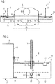
- FIG. 1 shows a combined sectional view and partial top view of a ceiling element 1 according to a first embodiment of the invention.
- Such ceiling elements 1 are called in particular when used for space cooling partly as a "cooling sail” and hanging suspended under a ceiling.
- arrangements with only one or more ceiling elements 1, typically arranged in a row, are possible.
- the ceiling element 1 comprises in the exemplary embodiment, a toothed rail 2, which has two suspensions 3 with a in the FIG. 1 Not shown ceiling are connected.
- the toothed rail 2 and the suspensions 3 together with others, in the FIG. 1 not apparent parts a support structure 4 of the ceiling element. 1
- the supporting structure 4 is used, inter alia, for fastening an air box 5 arranged in the viewing direction in front of the toothed rail 2 in a middle region of the ceiling element 1.
- the air box 5 has two fastening angles 8 on its side walls 10, which support the air box 5 on the toothed rail 2.
- the air box 5 further has an air inlet 6 located above the toothed rail 2 and an air outlet area 7 pointing in the direction of the interior of the room. Via the air inlet 6, the air box 5 and the air outlet area 7 can be supplied to a room supply air to improve the indoor climate.
- the supplied air can be humidified or dehumidified, heated or cooled if necessary.
- the two side walls 10 and two intermediate profile elements 9 of the air box 5 end in the air outlet region 7 each in a horizontal portion, for example, the short leg of an L-shaped angle.
- a strip-shaped magnetic fastening element 11 is arranged on the horizontal sections of the profile elements 9 and the side walls 10.
- the magnetic fastening elements 11 establish a connection between the air box 5 and a metallic ceiling plate 12 arranged underneath.
- the ceiling plate 12 has an air box 5 facing top and a to on the underside facing the air-conditioning space and is perforated at least in the region of the air box 5 in order to allow an escape of supply air into the room.
- the perforation 28 can also extend over the entire surface of the ceiling panel 12, for example for the purpose of an attractive interior design.
- connection means such as Velcro strips
- Velcro strips can be used instead of the magnetic fastening elements 11.
- these additionally serve to produce as close a connection as possible between the air box 5 and the ceiling plate 12, if necessary also for holding the ceiling plate 12 on the ceiling element 1.
- the holding force of the magnetic fastening elements 11 is sufficient to hold the relatively light ceiling plate 12 to the ceiling element 1.
- the ceiling plate 12 is further suspended pivotally on the toothed rail 2 via a hinge-like connection 13.
- the ceiling plate 12 is additionally connected via a latch 14 with the toothed rail 2, to prevent inadvertent opening of the ceiling plate 12.
- the latch 14 can either be operated manually or lock as a "rattle" when folding independently behind a projection of the ceiling plate 12.
- FIG. 2 shows details of the support structure 4 and other parts of the ceiling element 1 according to the embodiment according to FIG. 1 ,
- the dental splint 2 is fixed in height adjustable on two threaded nuts 15 on a threaded rod 16.
- the hinge-like connection 13 in the embodiment consists of a rectangular recess 17 on an upper side of the toothed rail 2 and an engaging therein, from the plane of extension of the ceiling plate 13 at right angles angled, the side edge of the ceiling element 1 embracing support member 18.
- This relatively simple mechanical construction allows a safe opening and closing of the ceiling plate 12 and at the same time offers the possibility of the ceiling plate 12 without using a tool by lifting in the unfolded state completely detached from the support structure 4 and re-hook.
- the mounting bracket 8 is indeed fixed by a screw 19 permanently on the side wall 10 of the air box 5, but rests only on the toothed rail 2 of the support structure 4.
- This design allows a mechanically secure, yet flexible connection between the air box 5 and the support structure 4, which is particularly advantageous in the reassembly of the air box 5 and allows tolerance compensation.
- Another fixation of the air box 5 can, as below with reference to the FIG. 3 described described.
- the tube assembly 24 includes a metallic, rail-shaped profile 20 which is attached to the toothed rail 2.
- a receptacle 21 for inserting a tube 22.
- the tube 22 is in the operation of the heating or cooling ceiling of a tempered medium, in particular water, flows through and thus serves to heat up or cool down an underlying room.
- a further strip-shaped, magnetic fastening element 23 is inserted, which establishes a direct and thus thermally conductive connection between a surface of the metallic profile 20 and an upper surface of the ceiling plate 12.
- On the underside of the ceiling plate 12 then takes place heating or cooling of the underlying space, in particular by thermal radiation.
- FIG. 3 shows schematically different views of a ceiling element 1 according to an embodiment of the invention.
- the register-shaped arrangement of the tubes 22 between two of a total of three toothed rails 2 of a support structure 4 can be seen.
- the mounting brackets 8 extend between a first, lateral toothed rail 2 a and a second, middle toothed rail 2 b of the supporting structure 4.
- the mounting brackets 8 are fixed via nuts 29 and stud bolts 30 to slots 31 of the toothed rails 2a and 2b for suspension.
- the air box 5 is completely surrounded in the plane shown by the flat fastener 11 so that its side walls 10 flush with the underlying ceiling plate 12. Contrary to the embodiment according to FIG.
- the arrangement does not have arranged in the air outlet 7 profile elements 7.
- the ceiling plate 12 is mounted on the right side in a recess 17 and secured on the opposite left side by means of a rotary latch 14.
- the air inlet 6 has a connecting piece for connecting a corresponding feed pipe or hose.
- FIGS. 4 and 5 views of two different configurations of such a ceiling element 1 with different large air boxes 5 are shown.
- the support structure 4 is configured in each case similar. Only the pipe assembly 24 is adapted so that it exploits the respective space not occupied by the air box 5 as well as possible.
- the ceiling plate 12 In order to allow ventilation of the lying under the ceiling plate 12 space, the ceiling plate 12 each have a perforation 28 in the air outlet 7.
- the terminals 25 and 26 are located on opposite sides of the ceiling element in the region of a third toothed rail 2c.
- the air box 5 extends essentially over the entire space available between a first toothed rail 2a and a second toothed rail 2b.
- the air box 5 extends in a horizontal x-direction over 520 mm of a ceiling element with a total plate length of 2425 mm.
- the air box 5 extends for example over a box length of 550 mm from a plate width of 850 mm.
- the air box 5 extends the air box 5 only approximately over a length which corresponds to half the distance between two adjacent toothed rails 2a and 2b. For example, it may have a length in the x-direction of 260 mm for a total length of the ceiling element of 2425 mm. In a perpendicular transverse direction y, the air box 5 again has a length of 550 mm, so that it can be fastened on the same support structure 4. The length of the air box depends on the free cross section of the ceiling plate 12. In this embodiment, a larger surface portion of the ceiling plate 12 is available for heating or cooling of an underlying space via the pipe assembly 24. Otherwise, the operation of the embodiments according to the FIGS. 4 and 5 equal.
- FIGS. 6 and 7 different perspective views of another embodiment of a ceiling element 1 can be seen.
- the assembly of the air box 5 on an upper side of a supporting structure 4 can be recognized.
- the ceiling element 1 is shown in an unfolded state. It can be seen in particular that in this state, the ceiling plate 12 hangs down into the room and so in particular their top can be cleaned with a perforation 28 therein by simply wiping.
- the air box 5, and in particular its interior is completely accessible in this state and likewise can be easily cleaned.
- the ceiling element 1 thus meets the hygiene requirements according to the VDI standard 6022 "Ventilation, indoor air quality".
- the supporting structure 4 can be fastened to a ceiling with a pipe arrangement 24 already mounted therein. Subsequently, the freely accessible terminals 25 and 26 with a pre-or
- the air box 5 can be placed on the support structure 4, connected via the air inlet 6 to a feed pipe and fixed to the toothed rails 2.
- the ceiling plate 12 is hung tool-free by means of the holding elements 18 in the recesses 17, folded by means of the hinge-like compound 13 formed on the ceiling and finally secured by the bolt 14 in the folded state. The relatively late attachment of the ceiling plate 12 prevents possible damage during the installation of the pipe assembly 24 and the air box fifth
Landscapes
- Engineering & Computer Science (AREA)
- Chemical & Material Sciences (AREA)
- Combustion & Propulsion (AREA)
- Mechanical Engineering (AREA)
- General Engineering & Computer Science (AREA)
- Life Sciences & Earth Sciences (AREA)
- Sustainable Development (AREA)
- Physics & Mathematics (AREA)
- Thermal Sciences (AREA)
- Duct Arrangements (AREA)
- Accommodation For Nursing Or Treatment Tables (AREA)
Abstract
- eine Tragkonstruktion (4) zum Befestigen des Deckenelements (1) an einer Raumdecke,
- eine an der Tragkonstruktion (4) befestigte Rohranordnung (24), die von einem Wärme transportierenden Medium durchströmbar ist,
- einen an der Tragkonstruktion (4) befestigten Luftkasten (5), der von Zuluft durchströmbar ist und einen Einlass (6) und einen Auslassbereich (7) aufweist; und
- eine an der Tragkonstruktion (4) befestigbare Deckenplatte (12), die eine Oberseite, eine Unterseite und eine Mehrzahl von Öffnungen im Bereich des Auslassbereichs (7) des Luftkastens (5) aufweist, wobei die Oberseite der Deckenplatte (12) über erste flächige, den Luftkasten (5) umgebende Verbindungsmittel lösbar mit dem Luftkasten (5) verbunden ist.
Description
- Die Erfindung betrifft ein Deckenelement, insbesondere einer Kühl- oder Heizdecke, aufweisend eine Tragkonstruktion zum Befestigen des Deckenelements an einer Raumdecke, eine an der Tragkonstruktion befestigte Rohranordnung, die von einem Wärme transportierenden Medium durchströmbar ist, und einen an der Tragkonstruktion befestigten Luftkasten, der von Zuluft durchströmbar ist und einen Einlass und einen Auslassbereich aufweist.
- Ein derartiges Deckenelement ist beispielsweise aus der europäischen Patentschrift
EP 1 586 823 B1 bekannt. - Für die Klimatisierung von Gebäuden finden raumlufttechnische Anlagen Anwendung, die einem geschlossenen Raum frische Luft zuführen und in Abhängigkeit von dem gewünschten Raumluftzustand diese erwärmen, kühlen, filtern, befeuchten oder entfeuchten. Neben herkömmlichen Klimaanlagen, welche die Raumtemperatur und die Luftfeuchte in einem Raum ausschließlich über die Zuluft auf vorgegebenen Werten halten, sind zunehmend häufiger Kühl- und Heizdecken anzutreffen, die geräuschlos eine angenehme und zugfreie Raumtemperatur erzeugen. Die Menge an Zuluft beschränkt sich in solchen Fällen auf den zur Aufrechterhaltung eines Hygienestandards erforderlichen Bedarf.
- Grund hierfür ist, dass bei einer Kühl- oder Heizdecke der gewünschte Effekt vornehmlich durch Strahlungsaustausch zwischen den gekühlten oder erwärmten Deckenflächen und dem Raum erfolgt. Demgegenüber wird bei herkömmlichen Klimaanlagen der Wärmeaustausch hauptsächlich durch erzwungene Konvektion, die beim Menschen Zugerscheinungen auslösen kann, erzielt. Darüber hinaus zeichnen sich Kühl- oder Heizdecken im Vergleich zu herkömmlichen Klimaanlagen durch einen geringeren Energieverbrauch und geringere Wartungs- und Instandsetzungskosten aus. Außer zum Kühlen oder Heizen lassen sich Kühl- und Heizdecken gewöhnlich auch zur Raumgestaltung, Lichtreflexion oder Schallabsorption verwenden.
- Ein Problem bekannter Kühl- oder Heizdecken besteht darin, dass sich insbesondere in einem Auslassbereich eines Deckenelements Verschmutzungen ansammeln können, die zu einer Beeinträchtigung des Hygienestandards des belüfteten Raums führen. Bedingt durch die Anordnung der Deckenelemente an einer Raumdecke sind diese zudem oft nur schwer zugänglich und somit nur mit verhältnismäßig großem Aufwand zu reinigen.
- Aufgabe der vorliegenden Erfindung ist es, ein verbessertes Deckenelement der oben genannten Art zu beschreiben, das besonders einfach oder gründlich gereinigt werden kann.
- Die oben genannte Aufgabe wird durch ein Deckenelement der oben genannten Art gelöst, dass eine an der Tragkonstruktion befestigbare Deckenplatte aufweist, wobei die Deckenplatte eine Oberseite, eine Unterseite und eine Mehrzahl von Öffnungen im Bereich des Auslassbereichs des Luftkastens aufweist, und wobei die Oberseite der Deckenplatte über erste flächige, den Luftkasten umgebende Verbindungsmittel lösbar mit dem Luftkasten verbunden ist.
- Durch das Vorsehen einer lösbaren Deckenplatte im Bereich eines Luftauslass eines Luftkastens können insbesondere in diesem Bereich auftretende Verunreinigungen leicht beseitigt werden. Beispielsweise kann die Deckenplatte von dem Deckenelement abgenommen oder weggeklappt, in einem abgenommenen oder aufgeklappten Zustand mit einem Lappen oder ähnlichem Reinigungselement abgewischt und nachfolgend wieder an dem Luftkasten befestigt beziehungsweise herangeklappt werden. Auch der Luftkasten selbst ist im gelösten Zustand der Deckenplatte vollständig zugänglich und kann somit besonders einfach und gründlich gereinigt werden. Durch Vorsehung der flächigen, den Luftkasten umgebende Verbindungsmittel ist im geschlossenen Zustand dabei eine hinreichende Dichtigkeit des Luftzuführungsweges des Deckenelements gewährleistet.
- In wenigstens einer Ausgestaltung weisen die ersten Verbindungsmittel wenigstens ein streifenförmiges Magnetelement auf. Die Verwendung von Magnetelementen ermöglicht eine besonders einfache Befestigung, was insbesondere bei Arbeiten im Bereich einer Zimmerdecke von Vorteil ist. Zudem ermöglichen sie die Herstellung einer verhältnismäßig luftdichten Verbindung zwischen dem Luftkasten und der Deckenplatte.
- In wenigstens einer Ausgestaltung ist die Oberseite der Deckenplatte über zweite flächige, im Bereich der Rohranordnung angeordnete Verbindungsmittel lösbar mit der Tragkonstruktion und/oder Rohranordnung verbunden. Durch weitere flächige, im Bereich der Rohranordnung angeordnete Verbindungsmittel kann eine sichere thermische Verbindung zwischen der Rohranordnung und dem Deckenelement sichergestellt werden.
- Beispielsweise weist die Rohranordnung eine Mehrzahl von Rohren, eine Mehrzahl von Profilen und eine Mehrzahl von streifenförmigen Magnetelementen auf, wobei die Mehrzahl von Rohren in Aufnahmevorrichtungen auf einer Oberseite der Mehrzahl von Profilen aufgenommen sind und die Mehrzahl von streifenförmigen Magnetelementen auf einer Unterseite in die Mehrzahl von Profilen eingelassen sind. Durch eine derartige Anordnung kann eine besonders einfache Montage beziehungsweise Demontage der Deckenplatte sichergestellt werden. Es ist von besonderem Vorteil, wenn die eingesetzten ersten und zweiten Verbindungsmittel gleichartig, beispielsweise als Magnetelemente, ausgeführt sind.
- In wenigstens einer Ausgestaltung sind die Deckenplatte und die Tragkonstruktion mittels einer scharnierartigen Verbindung im Bereich einer ersten Seitenkante des Deckenelements miteinander verbunden, sodass die Deckenplatte durch Lösen der flächigen Verbindungsmittel entlang der ersten Seitenkante von der Tragkonstruktion wegklappbar ist. Die Verwendung einer scharnierartigen Verbindung sichert die Deckenplatte gegen ein Herunterfallen von der Deckenkonstruktion.
- Beispielsweise kann die scharnierartige Verbindung wenigstens eine Vertiefung der Tragkonstruktion und wenigstens ein in die wenigstens eine Vertiefung eingreifendes Haltelement der Deckenplatte zum lösbaren Befestigen der Deckenplatte an der Tragkonstruktion aufweisen. Eine solche, mechanisch einfache Konstruktion gewährleistet sowohl ein sicheres Auf- und Zuklappen des Deckenelements als auch die Möglichkeit, das Deckenelement vollständig abnehmen zu können.
- In wenigstens einer Ausgestaltung ist die Deckenplatte in einem zugeklappten Zustand, in dem die ersten flächigen Verbindungsmittel die Oberseite der Deckenplatte mit dem Luftkasten verbinden, mittels wenigstens eines mechanischen Verschlusses im Bereich einer der ersten Seitenkante gegenüberliegenden zweiten Seitenkante des Deckenelements an der Tragkonstruktion gesichert. Ein derartiger Verschluss sichert das Deckenelement gegen ein unbeabsichtigtes Aufklappen der Deckenplatte.
- In wenigstens einer Ausgestaltung weist die Tragkonstruktion eine Mehrzahl von mechanisch miteinander gekoppelten Zahnschienen auf, wobei die Rohranordnung an den Zahnschienen befestigt ist. Eine solche Tragkonstruktion ist leicht zu fertigen und ermöglicht die Festlegung unterschiedlicher Ausgestaltungen von Rohranordnungen an einer ansonsten einheitlichen Tragkonstruktion. Beispielsweise können die Zahnschienen über einen umlaufenden Rahmen oder Profile der Rohranordnung selbst miteinander verbunden werden.
- In wenigstens einer Ausgestaltung weist die Tragkonstruktion und/oder der Luftkasten des Weiteren zwei Befestigungswinkel zur Fixierung des Luftkastens an der Tragkonstruktion auf. Eine derartige Anordnung ermöglicht insbesondere die einfache Remontage des Luftkastens, nachdem die Tragkonstruktion bereits an einer Raumdecke befestigt ist.
- Weitere vorteilhafte Ausgestaltungen der Erfindung sind in der nachfolgenden Beschreibung von Ausführungsbeispielen sowie den angehängten Patentansprüchen enthalten.
- Die Erfindung wird nachfolgend anhand von Ausführungsbeispielen unter Bezugnahme auf die angehängten Figuren im Detail beschrieben. In den Figuren zeigen:
-
Figur 1 eine schematische Darstellung eines Deckenelements gemäß einer Ausgestaltung der Erfindung, -
Figur 2 eine Detaildarstellung der Aufhängung des Deckenelements gemäßFigur 1 , -
Figur 3 schematische Ansichten auf ein Deckenelement gemäß einer Ausgestaltung der Erfindung, -
Figur 4 eine schematische Darstellung gemäß einer weiteren Ausgestaltung der Erfindung, -
Figur 5 eine schematische Darstellung gemäß einer weiteren Ausgestaltung der Erfindung, -
Figur 6 eine erste perspektivische Ansicht eines Deckenelements gemäß einer Ausgestaltung der Erfindung und -
Figur 7 eine zweite perspektivische Ansicht eines Deckenelements gemäß einer Ausgestaltung der Erfindung. -
Figur 1 zeigt eine kombinierte Schnittansicht und partielle Aufsicht eines Deckenelements 1 gemäß einer ersten Ausgestaltung der Erfindung. Solche Deckenelemente 1 werden insbesondere beim Einsatz zur Raumkühlung zum Teil auch als "Kühlsegel" bezeichnet und hängend unter einer Zimmerdecke befestigt. Je nach Größe des zu klimatisierenden Raums sind Anordnungen mit nur einem oder mehreren, typischerweise in einer Reihe angeordneten Deckenelementen 1 möglich. - Das Deckenelement 1 umfasst im Ausführungsbeispiel eine Zahnschiene 2, die über zwei Aufhängungen 3 mit einer in der
Figur 1 nicht dargestellten Zimmerdecke verbunden sind. Die Zahnschiene 2 und die Aufhängungen 3 bilden zusammen mit weiteren, in derFigur 1 nicht ersichtlichen Teilen eine Tragkonstruktion 4 des Deckenelementes 1. - Die Tragkonstruktion 4 dient unter anderem zur Befestigung eines in Betrachtungsrichtung vor der Zahnschiene 2 angeordneten Luftkastens 5 in einem mittleren Bereich des Deckenelements 1. Hierzu weist der Luftkasten 5 an seinen Seitenwänden 10 zwei Befestigungswinkel 8 auf, die den Luftkasten 5 auf der Zahnschiene 2 abstützen. Der Luftkasten 5 weist des Weiteren einen oberhalb der Zahnschiene 2 liegenden Lufteinlass 6 und einen in Richtung des Rauminneren weisenden Luftauslassbereich 7 auf. Über den Lufteinlass 6, den Luftkasten 5 und den Luftauslassbereich 7 kann einem Raum Zuluft zur Verbesserung des Raumklimas zugeführt werden. Die zugeführte Luft kann bei Bedarf be- oder entfeuchtet, erwärmt oder abgekühlt werden.
- Die zwei Seitenwände 10 sowie zwei dazwischenliegende Profilelemente 9 des Luftkastens 5 enden im Luftauslassbereich 7 jeweils in einem horizontalen Abschnitt, beispielsweise dem kurzen Schenkel eines L-förmigen Winkels. An den horizontalen Abschnitten der Profilelemente 9 und der Seitenwände 10 ist dabei jeweils ein streifenförmiges magnetisches Befestigungselement 11 angeordnet. Die magnetischen Befestigungselemente 11 stellen eine Verbindung zwischen dem Luftkasten 5 und einer darunter angeordneten, metallischen Deckenplatte 12 her. Die Deckenplatte 12 weist eine dem Luftkasten 5 zugewandte Oberseite und eine dem zu klimatisierenden Raum zugewandte Unterseite auf und ist zumindest im Bereich des Luftkastens 5 perforiert, um einen Austritt von Zuluft in den Raum zu ermöglichen. Die Perforation 28 kann sich auch über die gesamte Fläche der Deckenplatte 12 erstecken, beispielsweise zum Zweck einer ansprechenden Innenraumgestaltung.
- Anstelle der magnetischen Befestigungselemente 11 können auch andere flächige, lösbare Verbindungsmittel, wie beispielsweise Klettstreifen, Verwendung finden. Je nach Haltekraft der Verbindungsmittel dienen diese zusätzlich zur Herstellung einer möglichst dichten Verbindung zwischen dem Luftkasten 5 und der Deckenplatte 12 gegebenenfalls auch zum Halten der Deckenplatte 12 an dem Deckenelement 1.
- Im beschriebenen Ausführungsbeispiel ist die Haltekraft der magnetischen Befestigungselemente 11 ausreichend, um die relativ leichte Deckenplatte 12 an dem Deckenelement 1 festzuhalten. Zur Verbesserung der Sicherheit und zur weiteren Vereinfachung eines Reinigungsvorgangs ist die Deckenplatte 12 des Weiteren über eine scharnierartige Verbindung 13 schwenkbar an der Zahnschiene 2 aufgehängt. An einem der scharnierartigen Verbindung 13 gegenüberliegenden Ende der Zahnschiene 2 ist die Deckenplatte 12 zusätzlich über einen Riegel 14 mit der Zahnschiene 2 verbunden, um ein unbeabsichtigtes Aufklappen der Deckenplatte 12 zu verhindern. Der Riegel 14 kann entweder manuell betätigt werden oder als "Schapper" beim Hochklappen selbstständig hinter einem Vorsprung der Deckenplatte 12 verrasten.
-
Figur 2 zeigt Details der Tragkonstruktion 4 und weiterer Teile des Deckenelements 1 gemäß der Ausgestaltung nachFigur 1 . Insbesondere ist hierin zu erkennen, dass die Zahnschiene 2 über zwei Schraubenmuttern 15 höhenverstellbar an einer Gewindestange 16 befestigt ist. Zudem ist zu erkennen, dass die scharnierartige Verbindung 13 im Ausführungsbeispiel aus einer rechteckförmigen Vertiefung 17 an einer Oberseite der Zahnschiene 2 sowie einem darin eingreifenden, aus der Erstreckungsebene der Deckenplatte 12 dreifach rechtwinklig abgewinkelten, die Seitenkante des Deckenelements 1 umgreifenden Halteelement 18 besteht. Diese verhältnismäßig einfache mechanische Konstruktion erlaubt ein sicheres Aufund Zuklappen der Deckenplatte 12 und bietet gleichzeitig die Möglichkeit, die Deckenplatte 12 ohne Verwendung eines Werkzeugs durch Anheben im aufgeklappten Zustand vollständig von der Tragkonstruktion 4 zu lösen und wieder einzuhängen. - Zudem ist in der
Figur 2 zu erkennen, dass der Befestigungswinkel 8 zwar durch eine Schraube 19 permanent an der Seitenwand 10 des Luftkastens 5 befestigt ist, jedoch lediglich auf der Zahnschiene 2 der Tragkonstruktion 4 aufliegt. Diese Konstruktion erlaubt eine mechanisch sichere und doch flexible Verbindung zwischen Luftkasten 5 und der Tragkonstruktion 4, was insbesondere bei der Remontage des Luftkastens 5 von Vorteil ist und einen Toleranzausgleich ermöglicht. Eine weitere Fixierung des Luftkastens 5 kann wie unten unter Bezugnahme auf dieFigur 3 beschrieben erfolgen. - Schließlich ist in der
Figur 2 auch ein Teil einer Rohranordnung 24 zu erkennen, die wärmeleitend mit der Deckenplatte 12 verbunden ist. Die Rohranordnung 24 umfasst ein metallisches, schienenförmiges Profil 20, das an der Zahnschiene 2 befestigt ist. In das Profil 20 eingelassen ist eine Aufnahme 21 zum Einlegen eines Rohres 22. Das Rohr 22 wird im Betrieb der Heiz- oder Kühldecke von einem temperierten Medium, insbesondere Wasser, durchströmt und dient so zum Aufheizen beziehungsweise Abkühlen eines darunterliegenden Raums. Um eine gute Wärmeleitung von dem Rohr 22 zu der Deckenplatte 12 sicherzustellen, ist in das Profils 20 ein weiteres streifenförmiges, magnetisches Befestigungselement 23 eingelassen, das eine direkte und damit wärmeleitende Verbindung zwischen einer Oberfläche des metallischen Profils 20 und einer Oberseite der Deckenplatte 12 herstellt. Über die Unterseite der Deckenplatte 12 erfolgt dann eine Erwärmung oder Abkühlung des darunterliegenden Raums, insbesondere durch Wärmestrahlung. -
Figur 3 zeigt schematisch verschiedene Ansichten eines Deckenelements 1 gemäß einer Ausgestaltung der Erfindung. Darin ist insbesondere die registerförmige Anordnung der Rohre 22 zwischen zwei von insgesamt drei Zahnschienen 2 einer Tragkonstruktion 4 zu erkennen. Zudem ist zu erkennen, dass die Befestigungswinkel 8 sich zwischen einer ersten, seitlichen Zahnschiene 2a und einer zweiten, mittleren Zahnschiene 2b der Tragkonstruktion 4 erstecken. Die Befestigungswinkel 8 sind über Muttern 29 und Stehbolzen 30 an Langlöchern 31 der Zahnschienen 2a und 2b zur Abhängung fixiert. Der Luftkasten 5 ist in der dargestellten Ebene vollständig von dem flächigen Befestigungselement 11 umgeben, so dass seine Seitenwände 10 bündig mit der darunterliegenden Deckenplatte 12 abschließen. Entgegen der Ausgestaltung nachFigur 1 weist die Anordnung jedoch keine im Luftauslassbereich 7 angeordnete Profilelemente 7 auf. Die Deckenplatte 12 ist auf der rechten Seite in eine Vertiefung 17 eingehängt und auf der gegenüberliegenden linken Seite mittels eines Drehriegels 14 gesichert. Zur Zuführung von frischer Zuluft weist der Lufteinlass 6 einen Anschlussstutzen zum Anschluss eines entsprechenden Zuführungsrohrs oder -schlauchs auf. - In den
Figuren 4 und5 sind Ansichten von zwei unterschiedlichen Ausgestaltungen eines derartigen Deckenelements 1 mit unterschiedlichen großen Luftkästen 5 dargestellt. Die Tragkonstruktion 4 ist dabei jeweils gleichartig ausgestaltet. Nur die Rohranordnung 24 ist so angepasst, dass sie den jeweils nicht von dem Luftkasten 5 eingenommen Raum möglichst gut ausnutzt. Um eine Belüftung des unter der Deckenplatte 12 liegenden Raumes zu ermöglichen, weist die Deckenplatte 12 jeweils eine Perforation 28 im Luftauslassbereich 7 auf.
Ein Rohrregister endet jeweils in Anschlüssen 25 und 26 für einem Vorlauf- beziehungsweise Rücklaufkreis eines Heiz- oder Kühlkreislaufs. Im Ausführungsbeispiel befinden sich die Anschlüsse 25 und 26 auf gegenüberliegenden Seiten des Deckenelements im Bereich einer dritten Zahnschiene 2c. - In der Ausgestaltung gemäß
Figur 4 erstreckt sich der Luftkasten 5 im Wesentlichen über den gesamten zwischen einer ersten Zahnschiene 2a und einer zweiten Zahnschiene 2b zur Verfügung stehenden Raum. Beispielsweise erstreckt sich der Luftkasten 5 in einer horizontalen x-Richtung über 520 mm eines Deckenelements mit einer Plattenlänge von insgesamt 2425 mm. In einer sich dazu rechtwinklig erstreckenden, ebenfalls horizontalen y-Richtung erstreckt sich der Luftkasten 5 beispielsweise über eine Kastenlänge von 550 mm von einer Plattenbreite von 850 mm. - In der alternativen Ausgestaltung gemäß
Figur 5 erstreckt sich der Luftkasten 5 nur in etwa auf einer Länge, die dem halben Abstand zwischen zwei benachbarten Zahnschienen 2a und 2b entspricht. Beispielsweise kann er eine Länge in x-Richtung von 260 mm bei einer Gesamtlänge des Deckenelementes von 2425 mm aufweisen. In einer dazu senkrecht liegenden Querrichtung y weist der Luftkasten 5 wiederum eine Länge von 550 mm auf, sodass er auf derselben Tragkonstruktion 4 befestigt werden kann. Die Länge des Luftkastens hängt vom freien Querschnitt der Deckenplatte 12 ab. In diesem Ausführungsbeispiel steht ein größerer Flächenanteil der Deckenplatte 12 zum Erwärmen beziehungsweise Abkühlen eines darunterliegenden Raumes über die Rohranordnung 24 zur Verfügung. Ansonsten ist die Wirkungsweise der Ausgestaltungen gemäß denFiguren 4 und5 gleich. - In den
Figuren 6 und 7 sind unterschiedliche perspektivische Ansichten einer weiteren Ausgestaltung eines Deckenelements 1 zu erkennen. In derFigur 6 kann man insbesondere die Montage des Luftkastens 5 an einer Oberseite einer Tragkonstruktion 4 erkennen. In derFigur 7 ist das Deckenelement 1 in einem aufgeklappten Zustand dargestellt. Darin erkennt man insbesondere, dass in diesem Zustand die Deckenplatte 12 in den Raum herabhängt und so insbesondere ihre Oberseite mit einer darin befindlichen Perforation 28 durch einfaches Abwischen gereinigt werden kann. Zudem erkennt man, dass der Luftkasten 5, und insbesondere sein Innenraum, in diesem Zustand vollständig zugänglich ist und ebenfalls einfach gereinigt werden kann. Das Deckenelement 1 erfüllt somit auch die Hygienevorschriften gemäß der VDI-Norm 6022 "Raumlufttechnik, Raumluftqualität". - Neben der einfachen und wirksamen Reinigung und Wartung des Deckenelements 1, ist dieses auch besonders einfach zu montieren. In einem ersten Schritt kann die Tragkonstruktion 4 mit bereits darin montierter Rohranordnung 24 an einer Zimmerdecke befestigt werden. Nachfolgend können die frei zugänglichen Anschlüsse 25 und 26 mit einem Vor- bzw.
- Rücklauf eines Heiz- oder Kühlkreislaufs verbunden werden. Anschließend kann der Luftkasten 5 auf die Tragkonstruktion 4 aufgesetzt, über den Lufteinlass 6 an ein Zuführungsrohr angeschlossen und an den Zahnschienen 2 fixiert werden. Zuletzt wird die Deckenplatte 12 werkzeugfrei mittels der Haltelemente 18 in die Vertiefungen 17 eingehängt, mittels der so gebildeten scharnierartigen Verbindung 13 an die Zimmerdecke geklappt und abschließend durch den Riegel 14 im hochgeklappten Zustand gesichert. Das relativ späte Anbringen der Deckenplatte 12 verhindert dabei mögliche Beschädigungen derselben während der Installation der Rohranordnung 24 und des Luftkastens 5.
-
- 1
- Deckenelement
- 2
- Zahnschiene
- 3
- Aufhängung
- 4
- Tragkonstruktion
- 5
- Luftkasten
- 6
- Lufteinlass
- 7
- Luftauslassbereich
- 8
- Befestigungswinkel
- 9
- Profilelement
- 10
- Seitenwand
- 11
- Befestigungselement
- 12
- Deckenplatte
- 13
- scharnierartige Verbindung
- 14
- Riegel
- 15
- Schraubenmutter
- 16
- Gewindestange
- 17
- Vertiefung
- 18
- Halteelement
- 19
- Schraube
- 20
- Profil
- 21
- Aufnahme
- 22
- Rohr
- 23
- Befestigungselement
- 24
- Rohranordnung
- 25
- Anschluss (Vorlauf)
- 26
- Anschluss (Rücklauf)
- 28
- Perforation
- 29
- Mutter
- 30
- Stehbolzen
- 31
- Langloch
Claims (10)
- Deckenelement (1), insbesondere einer Kühl- oder Heizdecke, aufweisend:- eine Tragkonstruktion (4) zum Befestigen des Deckenelements (1) an einer Raumdecke,- eine an der Tragkonstruktion (4) befestigte Rohranordnung (24), die von einem Wärme transportierenden Medium durchströmbar ist,- einen an der Tragkonstruktion (4) befestigten Luftkasten (5), der von Zuluft durchströmbar ist und einen Einlass (6) und einen Auslassbereich (7) aufweist; und- eine an der Tragkonstruktion (4) befestigbare Deckenplatte (12), die eine Oberseite, eine Unterseite und eine Mehrzahl von Öffnungen im Bereich des Auslassbereichs (7) des Luftkastens (5) aufweist, wobei die Oberseite der Deckenplatte (12) über erste flächige, den Luftkasten (5) umgebende Verbindungsmittel lösbar mit dem Luftkasten (5) verbunden ist.
- Deckenelement (1) nach Anspruch 1, wobei die ersten Verbindungsmittel wenigstens ein streifenförmiges magnetisches Befestigungselement (11) aufweisen.
- Deckenelement (1) nach Anspruch 1 oder 2, wobei die Oberseite der Deckenplatte (12) über zweite flächige, im Bereich der Rohranordnung (24) angeordnete Verbindungsmittel lösbar mit der Tragkonstruktion (4) und/oder der Rohranordnung (24) verbunden ist.
- Deckenelement (1) nach Anspruch 3, wobei die Rohranordnung (24) eine Mehrzahl von Rohren (22), eine Mehrzahl von Profilen (20) und eine Mehrzahl von streifenförmigen magnetischen Befestigungselementen (23) aufweist, wobei die Mehrzahl von Rohren (22) in Aufnahmevorrichtungen auf einer Oberseite der Mehrzahl von Profilen (20) aufgenommen sind und die Mehrzahl von streifenförmigen magnetischen Befestigungselementen (23) auf einer Unterseite in die Mehrzahl von Profilen (20) eingelassen sind.
- Deckenelement (1) nach einem der Ansprüche 1 bis 4, wobei die Deckenplatte (12) und die Tragkonstruktion (4) mittels einer scharnierartigen Verbindung (13) im Bereich einer ersten Seitenkante des Deckenelements (1) miteinander verbunden sind, so dass die Deckenplatte (12) durch Lösen der flächigen Verbindungsmittel entlang der ersten Seitenkante von der Tragkonstruktion (4) wegklappbar ist.
- Deckenelement (1) nach Anspruch 5, wobei die scharnierartige Verbindung (13) wenigstens eine Vertiefung (17) der Tragkonstruktion (4) und wenigstens ein in die wenigstens eine Vertiefung (17) eingreifendes Haltelement (18) der Deckenplatte (12) zum lösbaren Befestigen der Deckenplatte (12) an der Tragkonstruktion (4) aufweist.
- Deckenelement (1) nach Anspruch 5 oder 6, wobei die Deckenplatte (12) in einem zugeklappten Zustand, in dem die ersten flächigen Verbindungsmittel die Oberseite der Deckenplatte (12) mit dem Luftkasten (5) verbinden, mittels wenigstens eines mechanischen Verschlusses im Bereich einer der ersten Seitenkante gegenüberliegenden zweiten Seitenkante des Deckenelements (1) an der Tragkonstruktion (4) gesichert ist.
- Deckenelement (1) nach Anspruch 7, wobei der wenigstens eine mechanische Verschluss einen an der Tragkonstruktion (4) befestigten Riegel (14) und einen an der Deckenplatte (12) geformten Hintergriff aufweist, der den Riegel (14) in einem verriegelten Zustand hintergreift.
- Deckenelement (1) nach einem der Ansprüche 1 bis 8, wobei die Tragkonstruktion (4) eine Mehrzahl von mechanisch miteinander gekoppelten Zahnschienen (2) aufweist, wobei die Rohranordnung (24) an den Zahnschienen (2) befestigt ist.
- Deckenelement (1) nach Anspruch 9, wobei die Tragkonstruktion (4) und/oder der Luftkasten (5) des Weiteren zwei Befestigungswinkel (8) zur Fixierung des Luftkastens (5) an der Tragkonstruktion (4) aufweist.
Applications Claiming Priority (1)
| Application Number | Priority Date | Filing Date | Title |
|---|---|---|---|
| DE202017100665.4U DE202017100665U1 (de) | 2017-02-08 | 2017-02-08 | Deckenelement, insbesondere einer Kühl- oder Heizdecke |
Publications (2)
| Publication Number | Publication Date |
|---|---|
| EP3361175A1 true EP3361175A1 (de) | 2018-08-15 |
| EP3361175B1 EP3361175B1 (de) | 2019-12-18 |
Family
ID=60269307
Family Applications (1)
| Application Number | Title | Priority Date | Filing Date |
|---|---|---|---|
| EP18153296.1A Active EP3361175B1 (de) | 2017-02-08 | 2018-01-24 | Deckenelement, insbesondere einer kühl- oder heizdecke |
Country Status (2)
| Country | Link |
|---|---|
| EP (1) | EP3361175B1 (de) |
| DE (1) | DE202017100665U1 (de) |
Cited By (1)
| Publication number | Priority date | Publication date | Assignee | Title |
|---|---|---|---|---|
| CN110285512A (zh) * | 2019-06-04 | 2019-09-27 | 上海工程技术大学 | 一种金属辐射吊顶板及其制备方法 |
Families Citing this family (2)
| Publication number | Priority date | Publication date | Assignee | Title |
|---|---|---|---|---|
| DE102020121124A1 (de) | 2020-08-11 | 2022-02-17 | As Led Lighting Gmbh | Deckenelement mit integrierter Beleuchtung |
| DE202023100456U1 (de) * | 2023-01-31 | 2024-05-07 | REHAU Industries SE & Co. KG | Heiz- und/oder Kühldecke sowie Wärmeleitlamellenanordnung dafür |
Citations (5)
| Publication number | Priority date | Publication date | Assignee | Title |
|---|---|---|---|---|
| DE3921719A1 (de) * | 1989-07-01 | 1991-01-10 | Wilhelmi Werke Gmbh & Co Kg | Deckenverkleidung |
| EP0552690A1 (de) * | 1992-01-22 | 1993-07-28 | SCHMIDT REUTER INGENIEURGESELLSCHAFT mbH & PARTNER KOMMANDITGESELLSCHAFT | Raumkühldecke |
| DE10219669A1 (de) * | 2002-05-02 | 2004-02-19 | Valentin Rosel | Kühl-Heiz-Lüftungsmodul |
| EP1777469A1 (de) * | 2005-10-18 | 2007-04-25 | Barcol-Air Ag | Kühlelement |
| WO2011152786A1 (en) * | 2010-05-31 | 2011-12-08 | Suncore Ab | Arrangement and system for climate control |
Family Cites Families (3)
| Publication number | Priority date | Publication date | Assignee | Title |
|---|---|---|---|---|
| FI113891B (fi) * | 1999-02-19 | 2004-06-30 | Halton Oy | Tuloilmalaite |
| DE102004018278B4 (de) | 2004-04-13 | 2006-01-19 | Thermosoft Klimatechnik Gmbh | Decke, insbesondere Kühl-oder Heizdecke |
| AT13655U1 (de) * | 2013-01-28 | 2014-05-15 | Schludermann Arnold | Kühldeckenelement |
-
2017
- 2017-02-08 DE DE202017100665.4U patent/DE202017100665U1/de not_active Expired - Lifetime
-
2018
- 2018-01-24 EP EP18153296.1A patent/EP3361175B1/de active Active
Patent Citations (5)
| Publication number | Priority date | Publication date | Assignee | Title |
|---|---|---|---|---|
| DE3921719A1 (de) * | 1989-07-01 | 1991-01-10 | Wilhelmi Werke Gmbh & Co Kg | Deckenverkleidung |
| EP0552690A1 (de) * | 1992-01-22 | 1993-07-28 | SCHMIDT REUTER INGENIEURGESELLSCHAFT mbH & PARTNER KOMMANDITGESELLSCHAFT | Raumkühldecke |
| DE10219669A1 (de) * | 2002-05-02 | 2004-02-19 | Valentin Rosel | Kühl-Heiz-Lüftungsmodul |
| EP1777469A1 (de) * | 2005-10-18 | 2007-04-25 | Barcol-Air Ag | Kühlelement |
| WO2011152786A1 (en) * | 2010-05-31 | 2011-12-08 | Suncore Ab | Arrangement and system for climate control |
Cited By (1)
| Publication number | Priority date | Publication date | Assignee | Title |
|---|---|---|---|---|
| CN110285512A (zh) * | 2019-06-04 | 2019-09-27 | 上海工程技术大学 | 一种金属辐射吊顶板及其制备方法 |
Also Published As
| Publication number | Publication date |
|---|---|
| DE202017100665U1 (de) | 2017-10-23 |
| EP3361175B1 (de) | 2019-12-18 |
Similar Documents
| Publication | Publication Date | Title |
|---|---|---|
| EP3361175B1 (de) | Deckenelement, insbesondere einer kühl- oder heizdecke | |
| DE3921719A1 (de) | Deckenverkleidung | |
| DE102013002641A1 (de) | Dachvoutenvorrichtung für ein Fahrzeug | |
| EP0658729B2 (de) | Lüftungssystem | |
| EP4433752A1 (de) | Umluftmodul und umluftmodulsystem | |
| DE69305538T2 (de) | Klimagerät | |
| EP2051017B1 (de) | Vorrichtung zur klimatisierung von räumen | |
| DE102005019578A1 (de) | Vorrichtung zum Heizen durch Fluidzirkulation | |
| EP3124869B1 (de) | Luftauslassgitter, insbesondere für einen ofen | |
| DE29704709U1 (de) | Heizungsgerät | |
| DE19710526A1 (de) | System von Klimageräten sowie Klimagerät | |
| EP0305335B1 (de) | Auslasskammer für die Zuluftverteilung in einen zu belüftenden Raum | |
| DE29701324U1 (de) | Lüftungsvorrichtung | |
| EP0236683B1 (de) | Lufteinlass-, Luftauslass- und/oder Luftverteilervorrichtung, insbesondere Lüftungsvorrichtung für Räume | |
| DE102012003383A1 (de) | Multifunktionselement für Raumwandungen und Vorrichtung zur Beleuchtung und Klimatisierung von Räumen | |
| AT4138U1 (de) | Lüftungsbeistoss für türzargen | |
| DE20103908U1 (de) | Windöffnung-Basisvorrichtung eines Gebläses für ein Klimagerät | |
| DE19514296A1 (de) | Heizkörper | |
| DE202008011462U1 (de) | Rollohalterahmen | |
| DE3839497A1 (de) | Gehaeuse fuer eine warmluftheizung mit luftfilter | |
| DE102015006762A1 (de) | Unterflurklimatisierungsvorrichtung | |
| DE29910037U1 (de) | Unterflurkonvektor | |
| DE10215596B4 (de) | Raum-Aufheizeinheit | |
| DE2455008C2 (de) | Filteranordnung mit rahmen und schalldaempfer fuer einbauluefter | |
| DE9201081U1 (de) | Rasterdecke für Reinräume |
Legal Events
| Date | Code | Title | Description |
|---|---|---|---|
| PUAI | Public reference made under article 153(3) epc to a published international application that has entered the european phase |
Free format text: ORIGINAL CODE: 0009012 |
|
| STAA | Information on the status of an ep patent application or granted ep patent |
Free format text: STATUS: THE APPLICATION HAS BEEN PUBLISHED |
|
| AK | Designated contracting states |
Kind code of ref document: A1 Designated state(s): AL AT BE BG CH CY CZ DE DK EE ES FI FR GB GR HR HU IE IS IT LI LT LU LV MC MK MT NL NO PL PT RO RS SE SI SK SM TR |
|
| AX | Request for extension of the european patent |
Extension state: BA ME |
|
| STAA | Information on the status of an ep patent application or granted ep patent |
Free format text: STATUS: REQUEST FOR EXAMINATION WAS MADE |
|
| RAP1 | Party data changed (applicant data changed or rights of an application transferred) |
Owner name: ZENT-FRENGER GMBH |
|
| 17P | Request for examination filed |
Effective date: 20190215 |
|
| RBV | Designated contracting states (corrected) |
Designated state(s): AL AT BE BG CH CY CZ DE DK EE ES FI FR GB GR HR HU IE IS IT LI LT LU LV MC MK MT NL NO PL PT RO RS SE SI SK SM TR |
|
| STAA | Information on the status of an ep patent application or granted ep patent |
Free format text: STATUS: EXAMINATION IS IN PROGRESS |
|
| 17Q | First examination report despatched |
Effective date: 20190809 |
|
| REG | Reference to a national code |
Ref country code: DE Ref legal event code: R079 Ref document number: 502018000505 Country of ref document: DE Free format text: PREVIOUS MAIN CLASS: F24F0013200000 Ipc: F24D0003160000 |
|
| GRAP | Despatch of communication of intention to grant a patent |
Free format text: ORIGINAL CODE: EPIDOSNIGR1 |
|
| STAA | Information on the status of an ep patent application or granted ep patent |
Free format text: STATUS: GRANT OF PATENT IS INTENDED |
|
| RIC1 | Information provided on ipc code assigned before grant |
Ipc: E04B 9/04 20060101ALI20190912BHEP Ipc: F24F 5/00 20060101ALI20190912BHEP Ipc: F24D 3/16 20060101AFI20190912BHEP Ipc: F24F 13/06 20060101ALI20190912BHEP Ipc: F24F 13/20 20060101ALI20190912BHEP |
|
| INTG | Intention to grant announced |
Effective date: 20191007 |
|
| GRAS | Grant fee paid |
Free format text: ORIGINAL CODE: EPIDOSNIGR3 |
|
| GRAA | (expected) grant |
Free format text: ORIGINAL CODE: 0009210 |
|
| STAA | Information on the status of an ep patent application or granted ep patent |
Free format text: STATUS: THE PATENT HAS BEEN GRANTED |
|
| AK | Designated contracting states |
Kind code of ref document: B1 Designated state(s): AL AT BE BG CH CY CZ DE DK EE ES FI FR GB GR HR HU IE IS IT LI LT LU LV MC MK MT NL NO PL PT RO RS SE SI SK SM TR |
|
| REG | Reference to a national code |
Ref country code: CH Ref legal event code: EP |
|
| REG | Reference to a national code |
Ref country code: IE Ref legal event code: FG4D Free format text: LANGUAGE OF EP DOCUMENT: GERMAN |
|
| REG | Reference to a national code |
Ref country code: DE Ref legal event code: R096 Ref document number: 502018000505 Country of ref document: DE |
|
| REG | Reference to a national code |
Ref country code: AT Ref legal event code: REF Ref document number: 1215035 Country of ref document: AT Kind code of ref document: T Effective date: 20200115 |
|
| REG | Reference to a national code |
Ref country code: NL Ref legal event code: MP Effective date: 20191218 |
|
| PG25 | Lapsed in a contracting state [announced via postgrant information from national office to epo] |
Ref country code: SE Free format text: LAPSE BECAUSE OF FAILURE TO SUBMIT A TRANSLATION OF THE DESCRIPTION OR TO PAY THE FEE WITHIN THE PRESCRIBED TIME-LIMIT Effective date: 20191218 Ref country code: LV Free format text: LAPSE BECAUSE OF FAILURE TO SUBMIT A TRANSLATION OF THE DESCRIPTION OR TO PAY THE FEE WITHIN THE PRESCRIBED TIME-LIMIT Effective date: 20191218 Ref country code: LT Free format text: LAPSE BECAUSE OF FAILURE TO SUBMIT A TRANSLATION OF THE DESCRIPTION OR TO PAY THE FEE WITHIN THE PRESCRIBED TIME-LIMIT Effective date: 20191218 Ref country code: NO Free format text: LAPSE BECAUSE OF FAILURE TO SUBMIT A TRANSLATION OF THE DESCRIPTION OR TO PAY THE FEE WITHIN THE PRESCRIBED TIME-LIMIT Effective date: 20200318 Ref country code: GR Free format text: LAPSE BECAUSE OF FAILURE TO SUBMIT A TRANSLATION OF THE DESCRIPTION OR TO PAY THE FEE WITHIN THE PRESCRIBED TIME-LIMIT Effective date: 20200319 Ref country code: BG Free format text: LAPSE BECAUSE OF FAILURE TO SUBMIT A TRANSLATION OF THE DESCRIPTION OR TO PAY THE FEE WITHIN THE PRESCRIBED TIME-LIMIT Effective date: 20200318 Ref country code: FI Free format text: LAPSE BECAUSE OF FAILURE TO SUBMIT A TRANSLATION OF THE DESCRIPTION OR TO PAY THE FEE WITHIN THE PRESCRIBED TIME-LIMIT Effective date: 20191218 |
|
| REG | Reference to a national code |
Ref country code: LT Ref legal event code: MG4D |
|
| PG25 | Lapsed in a contracting state [announced via postgrant information from national office to epo] |
Ref country code: RS Free format text: LAPSE BECAUSE OF FAILURE TO SUBMIT A TRANSLATION OF THE DESCRIPTION OR TO PAY THE FEE WITHIN THE PRESCRIBED TIME-LIMIT Effective date: 20191218 Ref country code: HR Free format text: LAPSE BECAUSE OF FAILURE TO SUBMIT A TRANSLATION OF THE DESCRIPTION OR TO PAY THE FEE WITHIN THE PRESCRIBED TIME-LIMIT Effective date: 20191218 |
|
| PG25 | Lapsed in a contracting state [announced via postgrant information from national office to epo] |
Ref country code: AL Free format text: LAPSE BECAUSE OF FAILURE TO SUBMIT A TRANSLATION OF THE DESCRIPTION OR TO PAY THE FEE WITHIN THE PRESCRIBED TIME-LIMIT Effective date: 20191218 |
|
| PG25 | Lapsed in a contracting state [announced via postgrant information from national office to epo] |
Ref country code: RO Free format text: LAPSE BECAUSE OF FAILURE TO SUBMIT A TRANSLATION OF THE DESCRIPTION OR TO PAY THE FEE WITHIN THE PRESCRIBED TIME-LIMIT Effective date: 20191218 Ref country code: EE Free format text: LAPSE BECAUSE OF FAILURE TO SUBMIT A TRANSLATION OF THE DESCRIPTION OR TO PAY THE FEE WITHIN THE PRESCRIBED TIME-LIMIT Effective date: 20191218 Ref country code: PT Free format text: LAPSE BECAUSE OF FAILURE TO SUBMIT A TRANSLATION OF THE DESCRIPTION OR TO PAY THE FEE WITHIN THE PRESCRIBED TIME-LIMIT Effective date: 20200513 Ref country code: CZ Free format text: LAPSE BECAUSE OF FAILURE TO SUBMIT A TRANSLATION OF THE DESCRIPTION OR TO PAY THE FEE WITHIN THE PRESCRIBED TIME-LIMIT Effective date: 20191218 Ref country code: NL Free format text: LAPSE BECAUSE OF FAILURE TO SUBMIT A TRANSLATION OF THE DESCRIPTION OR TO PAY THE FEE WITHIN THE PRESCRIBED TIME-LIMIT Effective date: 20191218 |
|
| PG25 | Lapsed in a contracting state [announced via postgrant information from national office to epo] |
Ref country code: SK Free format text: LAPSE BECAUSE OF FAILURE TO SUBMIT A TRANSLATION OF THE DESCRIPTION OR TO PAY THE FEE WITHIN THE PRESCRIBED TIME-LIMIT Effective date: 20191218 Ref country code: SM Free format text: LAPSE BECAUSE OF FAILURE TO SUBMIT A TRANSLATION OF THE DESCRIPTION OR TO PAY THE FEE WITHIN THE PRESCRIBED TIME-LIMIT Effective date: 20191218 Ref country code: IS Free format text: LAPSE BECAUSE OF FAILURE TO SUBMIT A TRANSLATION OF THE DESCRIPTION OR TO PAY THE FEE WITHIN THE PRESCRIBED TIME-LIMIT Effective date: 20200418 |
|
| REG | Reference to a national code |
Ref country code: DE Ref legal event code: R097 Ref document number: 502018000505 Country of ref document: DE |
|
| PG25 | Lapsed in a contracting state [announced via postgrant information from national office to epo] |
Ref country code: MC Free format text: LAPSE BECAUSE OF FAILURE TO SUBMIT A TRANSLATION OF THE DESCRIPTION OR TO PAY THE FEE WITHIN THE PRESCRIBED TIME-LIMIT Effective date: 20191218 |
|
| REG | Reference to a national code |
Ref country code: BE Ref legal event code: MM Effective date: 20200131 |
|
| PLBE | No opposition filed within time limit |
Free format text: ORIGINAL CODE: 0009261 |
|
| STAA | Information on the status of an ep patent application or granted ep patent |
Free format text: STATUS: NO OPPOSITION FILED WITHIN TIME LIMIT |
|
| PG25 | Lapsed in a contracting state [announced via postgrant information from national office to epo] |
Ref country code: ES Free format text: LAPSE BECAUSE OF FAILURE TO SUBMIT A TRANSLATION OF THE DESCRIPTION OR TO PAY THE FEE WITHIN THE PRESCRIBED TIME-LIMIT Effective date: 20191218 Ref country code: LU Free format text: LAPSE BECAUSE OF NON-PAYMENT OF DUE FEES Effective date: 20200124 Ref country code: DK Free format text: LAPSE BECAUSE OF FAILURE TO SUBMIT A TRANSLATION OF THE DESCRIPTION OR TO PAY THE FEE WITHIN THE PRESCRIBED TIME-LIMIT Effective date: 20191218 |
|
| 26N | No opposition filed |
Effective date: 20200921 |
|
| PG25 | Lapsed in a contracting state [announced via postgrant information from national office to epo] |
Ref country code: SI Free format text: LAPSE BECAUSE OF FAILURE TO SUBMIT A TRANSLATION OF THE DESCRIPTION OR TO PAY THE FEE WITHIN THE PRESCRIBED TIME-LIMIT Effective date: 20191218 Ref country code: BE Free format text: LAPSE BECAUSE OF NON-PAYMENT OF DUE FEES Effective date: 20200131 |
|
| PG25 | Lapsed in a contracting state [announced via postgrant information from national office to epo] |
Ref country code: FR Free format text: LAPSE BECAUSE OF NON-PAYMENT OF DUE FEES Effective date: 20200218 Ref country code: IE Free format text: LAPSE BECAUSE OF NON-PAYMENT OF DUE FEES Effective date: 20200124 Ref country code: IT Free format text: LAPSE BECAUSE OF FAILURE TO SUBMIT A TRANSLATION OF THE DESCRIPTION OR TO PAY THE FEE WITHIN THE PRESCRIBED TIME-LIMIT Effective date: 20191218 |
|
| PG25 | Lapsed in a contracting state [announced via postgrant information from national office to epo] |
Ref country code: PL Free format text: LAPSE BECAUSE OF FAILURE TO SUBMIT A TRANSLATION OF THE DESCRIPTION OR TO PAY THE FEE WITHIN THE PRESCRIBED TIME-LIMIT Effective date: 20191218 |
|
| PGFP | Annual fee paid to national office [announced via postgrant information from national office to epo] |
Ref country code: DE Payment date: 20220202 Year of fee payment: 5 Ref country code: CH Payment date: 20220125 Year of fee payment: 5 |
|
| PG25 | Lapsed in a contracting state [announced via postgrant information from national office to epo] |
Ref country code: TR Free format text: LAPSE BECAUSE OF FAILURE TO SUBMIT A TRANSLATION OF THE DESCRIPTION OR TO PAY THE FEE WITHIN THE PRESCRIBED TIME-LIMIT Effective date: 20191218 Ref country code: MT Free format text: LAPSE BECAUSE OF FAILURE TO SUBMIT A TRANSLATION OF THE DESCRIPTION OR TO PAY THE FEE WITHIN THE PRESCRIBED TIME-LIMIT Effective date: 20191218 Ref country code: CY Free format text: LAPSE BECAUSE OF FAILURE TO SUBMIT A TRANSLATION OF THE DESCRIPTION OR TO PAY THE FEE WITHIN THE PRESCRIBED TIME-LIMIT Effective date: 20191218 |
|
| PG25 | Lapsed in a contracting state [announced via postgrant information from national office to epo] |
Ref country code: MK Free format text: LAPSE BECAUSE OF FAILURE TO SUBMIT A TRANSLATION OF THE DESCRIPTION OR TO PAY THE FEE WITHIN THE PRESCRIBED TIME-LIMIT Effective date: 20191218 |
|
| GBPC | Gb: european patent ceased through non-payment of renewal fee |
Effective date: 20220124 |
|
| PG25 | Lapsed in a contracting state [announced via postgrant information from national office to epo] |
Ref country code: GB Free format text: LAPSE BECAUSE OF NON-PAYMENT OF DUE FEES Effective date: 20220124 |
|
| REG | Reference to a national code |
Ref country code: DE Ref legal event code: R119 Ref document number: 502018000505 Country of ref document: DE |
|
| REG | Reference to a national code |
Ref country code: CH Ref legal event code: PL |
|
| PG25 | Lapsed in a contracting state [announced via postgrant information from national office to epo] |
Ref country code: LI Free format text: LAPSE BECAUSE OF NON-PAYMENT OF DUE FEES Effective date: 20230131 Ref country code: CH Free format text: LAPSE BECAUSE OF NON-PAYMENT OF DUE FEES Effective date: 20230131 Ref country code: DE Free format text: LAPSE BECAUSE OF NON-PAYMENT OF DUE FEES Effective date: 20230801 |
|
| REG | Reference to a national code |
Ref country code: AT Ref legal event code: MM01 Ref document number: 1215035 Country of ref document: AT Kind code of ref document: T Effective date: 20230124 |
|
| PG25 | Lapsed in a contracting state [announced via postgrant information from national office to epo] |
Ref country code: AT Free format text: LAPSE BECAUSE OF NON-PAYMENT OF DUE FEES Effective date: 20230124 |
|
| PG25 | Lapsed in a contracting state [announced via postgrant information from national office to epo] |
Ref country code: AT Free format text: LAPSE BECAUSE OF NON-PAYMENT OF DUE FEES Effective date: 20230124 |
|
| PGFP | Annual fee paid to national office [announced via postgrant information from national office to epo] |
Ref country code: AT Payment date: 20260410 Year of fee payment: 5 |