EP3361054B1 - Flow path forming plate, stator vane and flow path forming member provided with flow path forming plate, gas turbine, method of manufacturing flow path forming plate, and method of remodeling flow path forming plate - Google Patents
Flow path forming plate, stator vane and flow path forming member provided with flow path forming plate, gas turbine, method of manufacturing flow path forming plate, and method of remodeling flow path forming plate Download PDFInfo
- Publication number
- EP3361054B1 EP3361054B1 EP16868450.4A EP16868450A EP3361054B1 EP 3361054 B1 EP3361054 B1 EP 3361054B1 EP 16868450 A EP16868450 A EP 16868450A EP 3361054 B1 EP3361054 B1 EP 3361054B1
- Authority
- EP
- European Patent Office
- Prior art keywords
- ledge
- wall
- vane
- suction
- main body
- Prior art date
- Legal status (The legal status is an assumption and is not a legal conclusion. Google has not performed a legal analysis and makes no representation as to the accuracy of the status listed.)
- Active
Links
Images


Classifications
-
- F—MECHANICAL ENGINEERING; LIGHTING; HEATING; WEAPONS; BLASTING
- F01—MACHINES OR ENGINES IN GENERAL; ENGINE PLANTS IN GENERAL; STEAM ENGINES
- F01D—NON-POSITIVE DISPLACEMENT MACHINES OR ENGINES, e.g. STEAM TURBINES
- F01D5/00—Blades; Blade-carrying members; Heating, heat-insulating, cooling or antivibration means on the blades or the members
- F01D5/12—Blades
- F01D5/14—Form or construction
- F01D5/18—Hollow blades, i.e. blades with cooling or heating channels or cavities; Heating, heat-insulating or cooling means on blades
- F01D5/187—Convection cooling
-
- F—MECHANICAL ENGINEERING; LIGHTING; HEATING; WEAPONS; BLASTING
- F01—MACHINES OR ENGINES IN GENERAL; ENGINE PLANTS IN GENERAL; STEAM ENGINES
- F01D—NON-POSITIVE DISPLACEMENT MACHINES OR ENGINES, e.g. STEAM TURBINES
- F01D5/00—Blades; Blade-carrying members; Heating, heat-insulating, cooling or antivibration means on the blades or the members
- F01D5/12—Blades
- F01D5/14—Form or construction
- F01D5/18—Hollow blades, i.e. blades with cooling or heating channels or cavities; Heating, heat-insulating or cooling means on blades
-
- F—MECHANICAL ENGINEERING; LIGHTING; HEATING; WEAPONS; BLASTING
- F01—MACHINES OR ENGINES IN GENERAL; ENGINE PLANTS IN GENERAL; STEAM ENGINES
- F01D—NON-POSITIVE DISPLACEMENT MACHINES OR ENGINES, e.g. STEAM TURBINES
- F01D25/00—Component parts, details, or accessories, not provided for in, or of interest apart from, other groups
- F01D25/08—Cooling; Heating; Heat-insulation
- F01D25/12—Cooling
-
- F—MECHANICAL ENGINEERING; LIGHTING; HEATING; WEAPONS; BLASTING
- F01—MACHINES OR ENGINES IN GENERAL; ENGINE PLANTS IN GENERAL; STEAM ENGINES
- F01D—NON-POSITIVE DISPLACEMENT MACHINES OR ENGINES, e.g. STEAM TURBINES
- F01D25/00—Component parts, details, or accessories, not provided for in, or of interest apart from, other groups
- F01D25/08—Cooling; Heating; Heat-insulation
- F01D25/14—Casings modified therefor
-
- F—MECHANICAL ENGINEERING; LIGHTING; HEATING; WEAPONS; BLASTING
- F01—MACHINES OR ENGINES IN GENERAL; ENGINE PLANTS IN GENERAL; STEAM ENGINES
- F01D—NON-POSITIVE DISPLACEMENT MACHINES OR ENGINES, e.g. STEAM TURBINES
- F01D9/00—Stators
- F01D9/02—Nozzles; Nozzle boxes; Stator blades; Guide conduits, e.g. individual nozzles
- F01D9/04—Nozzles; Nozzle boxes; Stator blades; Guide conduits, e.g. individual nozzles forming ring or sector
- F01D9/041—Nozzles; Nozzle boxes; Stator blades; Guide conduits, e.g. individual nozzles forming ring or sector using blades
-
- F—MECHANICAL ENGINEERING; LIGHTING; HEATING; WEAPONS; BLASTING
- F02—COMBUSTION ENGINES; HOT-GAS OR COMBUSTION-PRODUCT ENGINE PLANTS
- F02C—GAS-TURBINE PLANTS; AIR INTAKES FOR JET-PROPULSION PLANTS; CONTROLLING FUEL SUPPLY IN AIR-BREATHING JET-PROPULSION PLANTS
- F02C3/00—Gas-turbine plants characterised by the use of combustion products as the working fluid
- F02C3/04—Gas-turbine plants characterised by the use of combustion products as the working fluid having a turbine driving a compressor
-
- F—MECHANICAL ENGINEERING; LIGHTING; HEATING; WEAPONS; BLASTING
- F02—COMBUSTION ENGINES; HOT-GAS OR COMBUSTION-PRODUCT ENGINE PLANTS
- F02C—GAS-TURBINE PLANTS; AIR INTAKES FOR JET-PROPULSION PLANTS; CONTROLLING FUEL SUPPLY IN AIR-BREATHING JET-PROPULSION PLANTS
- F02C7/00—Features, components parts, details or accessories, not provided for in, or of interest apart form groups F02C1/00 - F02C6/00; Air intakes for jet-propulsion plants
- F02C7/12—Cooling of plants
-
- F—MECHANICAL ENGINEERING; LIGHTING; HEATING; WEAPONS; BLASTING
- F05—INDEXING SCHEMES RELATING TO ENGINES OR PUMPS IN VARIOUS SUBCLASSES OF CLASSES F01-F04
- F05D—INDEXING SCHEME FOR ASPECTS RELATING TO NON-POSITIVE-DISPLACEMENT MACHINES OR ENGINES, GAS-TURBINES OR JET-PROPULSION PLANTS
- F05D2220/00—Application
- F05D2220/30—Application in turbines
- F05D2220/32—Application in turbines in gas turbines
-
- F—MECHANICAL ENGINEERING; LIGHTING; HEATING; WEAPONS; BLASTING
- F05—INDEXING SCHEMES RELATING TO ENGINES OR PUMPS IN VARIOUS SUBCLASSES OF CLASSES F01-F04
- F05D—INDEXING SCHEME FOR ASPECTS RELATING TO NON-POSITIVE-DISPLACEMENT MACHINES OR ENGINES, GAS-TURBINES OR JET-PROPULSION PLANTS
- F05D2230/00—Manufacture
- F05D2230/20—Manufacture essentially without removing material
- F05D2230/21—Manufacture essentially without removing material by casting
-
- F—MECHANICAL ENGINEERING; LIGHTING; HEATING; WEAPONS; BLASTING
- F05—INDEXING SCHEMES RELATING TO ENGINES OR PUMPS IN VARIOUS SUBCLASSES OF CLASSES F01-F04
- F05D—INDEXING SCHEME FOR ASPECTS RELATING TO NON-POSITIVE-DISPLACEMENT MACHINES OR ENGINES, GAS-TURBINES OR JET-PROPULSION PLANTS
- F05D2230/00—Manufacture
- F05D2230/20—Manufacture essentially without removing material
- F05D2230/23—Manufacture essentially without removing material by permanently joining parts together
- F05D2230/232—Manufacture essentially without removing material by permanently joining parts together by welding
-
- F—MECHANICAL ENGINEERING; LIGHTING; HEATING; WEAPONS; BLASTING
- F05—INDEXING SCHEMES RELATING TO ENGINES OR PUMPS IN VARIOUS SUBCLASSES OF CLASSES F01-F04
- F05D—INDEXING SCHEME FOR ASPECTS RELATING TO NON-POSITIVE-DISPLACEMENT MACHINES OR ENGINES, GAS-TURBINES OR JET-PROPULSION PLANTS
- F05D2240/00—Components
- F05D2240/80—Platforms for stationary or moving blades
- F05D2240/81—Cooled platforms
-
- F—MECHANICAL ENGINEERING; LIGHTING; HEATING; WEAPONS; BLASTING
- F05—INDEXING SCHEMES RELATING TO ENGINES OR PUMPS IN VARIOUS SUBCLASSES OF CLASSES F01-F04
- F05D—INDEXING SCHEME FOR ASPECTS RELATING TO NON-POSITIVE-DISPLACEMENT MACHINES OR ENGINES, GAS-TURBINES OR JET-PROPULSION PLANTS
- F05D2260/00—Function
- F05D2260/20—Heat transfer, e.g. cooling
- F05D2260/201—Heat transfer, e.g. cooling by impingement of a fluid
Definitions
- the present invention relates to a flow passage forming plate that defines a part of a gas flow passage through which combustion gas flows in a gas turbine, a flow passage forming member assembly and a vane including this flow passage forming plate, a gas turbine, a manufacturing method of a flow passage forming plate, and a modification method of a flow passage forming plate.
- a gas turbine includes a compressor that generates compressed air by compressing atmospheric air, a combustor that generates combustion gas by combusting fuel in the compressed air, and a turbine that is driven by the combustion gas.
- the turbine has a turbine rotor that rotates around an axis, a plurality of vane rows that are arrayed in an axial direction in which the axis extends, and a turbine casing that rotatably covers the turbine rotor.
- the turbine rotor has a rotor shaft that extends in the axial direction around the axis, and a plurality of blade rows that are fixed to the rotor shaft.
- the plurality of blade rows each have a plurality of blades that are arrayed in a circumferential direction around the axis.
- One vane row of the plurality of vane rows is disposed on the upstream side of each of the plurality of blade rows.
- the plurality of vane rows each have a plurality of vanes that are arrayed in
- the blade has a blade body extending in a radial direction, and a platform provided on the radially inner side of the blade body.
- the vane has a vane body extending in the radial direction, an inner shroud provided on the radially inner side of the vane body, and an outer shroud provided on the radially outer side of the vane body.
- Each of the platform of the blade and the inner shroud and the outer shroud of the vane is a flow passage forming plate that defines a part of a gas flow passage through which combustion gas flows.
- ring segments that constitute a part of the turbine casing and are disposed on the radially outer side of the blades are also flow passage forming plates that define a part of the gas flow passage.
- Each of these flow passage forming plates is exposed to high-temperature combustion gas, and therefore needs to be cooled with cooling air, for example.
- JP 5676040 B discloses a technique of cooling the inner shroud of a vane, which is a flow passage forming plate, with cooing air from the radially inner side of the inner shroud.
- This inner shroud has a shroud plate main body and a peripheral wall that is provided along a peripheral edge of the shroud plate main body.
- the shroud plate main body has a gas path surface facing the side of a gas flow passage through which combustion gas flows, and an inner surface facing the opposite side from the gas path surface.
- the peripheral wall protrudes toward the radially inner side relative to the inner surface of the shroud plate main body.
- This inner shroud has an impingement plate provided inside a region surrounded by the peripheral wall, at a position separated from the inner surface of the shroud plate main body toward the radially inner side.
- This impingement plate has a plurality of through-holes.
- This impingement plate is supported by a ledge that protrudes along an inner wall surface of the peripheral wall, from the inner surface of the shroud plate main body toward the radially inner side.
- Cooling air is blown out of the plurality of through-holes of the impingement plate toward the inner surface of the shroud plate main body.
- the shroud plate main body having the gas path surface is impingement-cooled by this cooling air.
- JP 2003-083001 A discloses a flow passage forming plate for a gas turbine on which the preamble portion of the new claim 1 is based.
- the flow passage forming plate is provided with a ledge that protrudes along an inner wall surface of the peripheral wall to the opposite flow-passage side and is also configured to receive, in a mounted state, an impingement plate having a plurality of through-holes.
- US 2010/129196 A1 discloses a cooled gas turbine vane assembly which also has a ledge formed in a part of the flow passage forming plate of the stator vane that is to support, in a mounted state, an impingement plate with a plurality of through-holes.
- US 4693667 A discloses a turbine inlet nozzle with cooling means.
- An impingement plate with a plurality of through-holes is supported on a ledge in an upper and lower flow passage forming plate (shroud) of a stator vane.
- an object of the present invention is to provide a technique that can enhance the cooling effect of cooling air on flow passage forming plates.
- a flow passage forming plate according to the present invention to achieve the above object is a flow passage forming plate with the features of claim 1 that defines a part of a gas flow passage through which combustion gas flows in a gas turbine, the flow passage forming plate including:
- the ledge of the flow passage forming plate that receives the impingement plate is formed not along the entire inner wall surface of the peripheral wall but along only a part of the inner wall surface of the peripheral wall.
- the ledge is not provided in a part of the inner wall surface of the peripheral wall.
- the through-holes of the impingement plate can be formed close to the inner wall surface of the peripheral wall so that the inner wall surface of the peripheral wall, and moreover a part of the inner surface of the plate main body that is close to the inner wall surface of the peripheral wall can be effectively cooled with cooling air flowing through these through-holes into an inner cavity between the plate main body and the impingement plate.
- an outer wall surface of the peripheral wall, and moreover a part of the gas path surface that extends along the peripheral wall can be effectively cooled.
- the wall between the inner cavity and an outer space on the opposite side based on that part has a smaller thickness, so that, compared with the part where the ledge is provided, cooling of the plate main body having the gas path surface is promoted and the temperature of the gas path surface can be reduced. In this respect, too, the cooling effect on this flow passage forming plate can be enhanced.
- the ledge includes a first ledge and a second ledge that are separated from each other in the wall extension direction.
- a flow passage forming member assembly according to the present invention to achieve the above object includes the features of claim 2 comprising the flow passage forming plate of the invention; the impingement plate that is supported on the ledge of the flow passage forming plate; and a welded part that connects the flow passage forming plate and the impingement plate to each other.
- a vane according to the present invention to achieve the above object includes the features of claim 3 comprising the flow passage forming member assembly of the invention, and a vane body that has an airfoil shape and extends from the gas path surface of the flow passage forming plate toward the flow passage side opposite from the opposite-flow-passage side, wherein the plate main body has a front end surface that is an end surface on the side of a leading edge of the vane body relative to a trailing edge of the vane body, a back end surface that faces the opposite side from the front end surface, a pressure-side end surface that is an end surface on the side of a pressure-side surface of the vane body relative to a suction-side surface of the vane body, and a suction-side end surface that faces the opposite side from the pressure-side end surface.
- a vane of a preferred embodiment is the vane of the invention, including a front wall that is a part of the peripheral wall and provided along the front end surface of the plate main body, wherein the ledge includes a first front ledge and a second front ledge that extend along the front wall and are separated from each other in a front wall extension direction in which the front wall extends, and the leading edge of the vane body is located between the first front ledge and the second front ledge in the front wall extension direction.
- the distance between the leading edge of the vane body and an inner peripheral surface of the front wall in a direction from the leading edge toward the trailing edge of the vane body is short. Accordingly, it is difficult to provide the through-holes of the impingement plate in this space, and it is difficult to cool this space with cooling air.
- the front ledge is not provided in the region in which the leading edge of the vane body is located in the front wall extension direction in which the front wall extends. Thus, the region of the flow passage forming plate that is easily heated and not easily cooled can be cooled in this vane.
- a vane of a preferred embodiment is the vane of the invention, including a suction-side wall that is a part of the peripheral wall and provided along the suction-side end surface of the plate main body, wherein the ledge includes a first suction-side ledge and a second suction-side ledge that extend along the suction-side wall and are separated from each other in a suction-side wall extension direction in which the suction-side wall extends, and a part of the suction-side surface of the vane body that is closest to the suction-side end surface of the plate main body is located between the first suction-side ledge and the second suction-side ledge in the suction-side wall extension direction.
- the distance between the part of the suction-side surface of the vane body that is closest to the suction-side end surface of the plate main body and an inner wall surface of the suction-side wall is short. Accordingly, it is difficult to provide the through-holes of the impingement plate in this space, and it is difficult to cool this space with cooling air.
- the suction-side ledge is not provided in the part of the suction-side surface of the vane body that is closest to the suction-side end surface of the plate main body in the suction-side wall extension direction in which the suction-side wall extends. Thus, the region of the flow passage forming plate that is not easily cooled can be cooled in this vane.
- a gas turbine according to the present invention to achieve the above object includes the features of claim 6 comprising the flow passage forming member assembly of the invention, and a combustor that generates the combustion gas by combusting fuel.
- a gas turbine according to the present invention to achieve the above object includes the features of claim 7 comprising the vane of the invention, and a combustor that generates the combustion gas by combusting fuel.
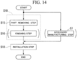
- a manufacturing method of a flow passage forming plate according to the present invention to achieve the above object comprises the features of claim 8 and is a manufacturing method of a flow passage forming plate that defines a part of a gas flow passage through which combustion gas flows in a gas turbine, the manufacturing method including:
- a preferred embodiment of the manufacturing method of a flow passage forming plate is the manufacturing method of the invention, wherein, in the part removing step, a part of the plate main body on the side of the inner surface is removed so as to reduce the interval between the gas path surface and the inner surface of the plate main body.
- a modification method of a flow passage forming plate according to the present invention to achieve the above object comprises the features of claim 10 and is a modification method of a flow passage forming plate that defines a part of a gas flow passage through which combustion gas flows in a gas turbine, the flow passage forming plate to be modified including:
- a preferred embodiment of the modification method of a flow passage forming plate is the modification method of the invention, wherein, in the part removing step, a part of the plate main body on the side of the inner surface is removed so as to reduce the interval between the gas path surface and the inner surface of the plate main body.
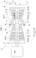
- a gas turbine 10 as the embodiment according to the present invention includes a compressor 20 that compresses air A, combustors 30 that generate combustion gas by combusting fuel F in the air A compressed by the compressor 20, and a turbine 40 that is driven by the combustion gas.
- the compressor 20 has a compressor rotor 21 that rotates around an axis Ar, a compressor casing 25 that covers the compressor rotor 21, and a plurality of vane rows 26.
- the turbine 40 has a turbine rotor 41 that rotates around the axis Ar, a turbine casing 45 that covers the turbine rotor 41, and a plurality of vane rows 46.
- the compressor rotor 21 and the turbine rotor 41 are located on the same axis Ar, and are connected to each other to form a gas turbine rotor 11.
- a rotor of a generator GEN is connected to the gas turbine rotor 11.
- the gas turbine 10 further includes an intermediate casing 14 that is disposed between the compressor casing 25 and the turbine casing 45.
- the combustors 30 are mounted on the intermediate casing 14.
- the compressor casing 25, the intermediate casing 14, and the turbine casing 45 are connected to one another to form a gas turbine casing 15.
- a direction in which the axis Ar extends will be referred to as an axial direction Da.
- a circumferential direction around the axis Ar will be referred to simply as a circumferential direction Dc, and a direction perpendicular to the axis Ar will be referred to as a radial direction Dr.
- a direction perpendicular to the axis Ar will be referred to as a radial direction Dr.
- the side of the compressor 20 based on the turbine 40 and the opposite side will be referred to as an upstream side Dau and a downstream side Dad, respectively.
- the side closer to the axis Ar and the opposite side will be referred to as a radially inner side Dri and a radially outer side Dro, respectively.
- the compressor rotor 21 has a rotor shaft 22 that extends in the axial direction Da around the axis Ar, and a plurality of blade rows 23 that are mounted on the rotor shaft 22.
- the plurality of blade rows 23 are arrayed in the axial direction Da.
- Each blade row 23 is composed of a plurality of blades 23a that are arrayed in the circumferential direction Dc.
- the vane row 26 is disposed on the upstream side Dau of each of the plurality of blade rows 23.
- the vane rows 26 are provided on an inner side of the compressor casing 25.
- Each vane row 26 is composed of a plurality of vanes 26a that are arrayed in the circumferential direction Dc.
- the turbine rotor 41 has a rotor shaft 42 that extends in the axial direction Da around the axis Ar, and a plurality of blade rows 43 that are mounted on the rotor shaft 42.
- the plurality of blade rows 43 are arrayed in the axial direction Da.
- Each blade row 43 is composed of a plurality of blades 43a that are arrayed in the circumferential direction Dc.
- the vane row 46 is disposed on the upstream side Dau of each of the plurality of blade rows 43.
- the vane rows 46 are provided on an inner side of the turbine casing 45.
- Each vane row 46 is composed of a plurality of vanes 50 that are arrayed in the circumferential direction Dc.
- the turbine casing 45 has a cylindrical outer casing 45a that constitutes an outer shell of the turbine casing 45, an inner casing 45b that is fixed on an inner side of the outer casing 45a, a plurality of ring segments 90 that are fixed on an inner side of the inner casing 45b, and an isolation ring 45c that connects the vane 50 and the ring segment 90 to the inner casing 45b.
- the plurality of ring segments 90 are each provided at a position between the adjacent vane rows 46.
- the blade row 43 is disposed on the radially inner side Dri of each ring segment 90.
- An annular space which is defined between an outer circumferential side of the rotor shaft 42 and an inner circumferential side of the turbine casing 45 and in which the vanes 50 and the blades 43a are disposed in the axial direction Da forms a combustion gas flow passage 49 through which combustion gas G from the combustors 30 flows.
- the combustion gas flow passage 49 has an annular shape around the axis Ar, and is long in the axial direction Da.
- the inner casing 45b of the turbine casing 45 has cooling air passages 45p that are formed so as to extend therethrough from the radially outer side Dro to the radially inner side Dri.
- Cooling air having passed through the cooling air passage 45p is introduced into the vane 50 and the ring segment 90, and is used to cool the vane 50 and the ring segment 90.
- air inside the gas turbine casing 15 may be supplied as cooling air to the vanes 50 composing the vane row 46, without passing through the cooling air passage of the turbine casing 45.
- the blade 43a of the turbine 40 has a blade body 43b that extends in the radial direction Dr, a platform 43p that is formed on the radially inner side Dri of the blade body, and a blade root 43r that is formed on the radially inner side Dri of the platform 43p.
- the blade body 43b is disposed in the combustion gas flow passage 49 through which the combustion gas G passes.
- the platform 43p defines the position of the annular combustion gas flow passage 49 on the radially inner side Dri.
- the ring segment 90 disposed on the radially outer side Dro of the blade 43a defines the position of the annular combustion gas flow passage 49 on the radially outer side Dro.
- each of the platform 43p of the blade 43a and the ring segment 90 constitutes a flow passage forming plate.
- the blade root 43r is fitted in the rotor shaft 42.
- the vane 50 of the turbine 40 has a vane body 51 that extends in the radial direction Dr, an inner shroud 60i that is formed on the radially inner side Dri of the vane body 51, and an outer shroud 60o that is formed on the radially outer side Dro of the vane body 51.
- the vane body 51 is disposed in the combustion gas flow passage 49 through which the combustion gas G passes.
- the inner shroud 60i defines the position of the annular combustion gas flow passage 49 on the radially inner side Dri.
- the outer shroud 60o defines the position of the annular combustion gas flow passage 49 on the radially outer side Dro.
- the vane body 51 has an airfoil shape.
- An end of the vane body 51 on the upstream side Dau forms a leading edge 52, and an end thereof on the downstream side Dad forms a trailing edge 53.
- Fillets 56 are formed along the entire circumference of the vane body 51, respectively at a joint between the vane body 51 and the inner shroud 60i and a joint between the vane body 51 and the outer shroud 60o.
- the upstream side Dau in the axial direction Da and the downstream side Dad in the axial direction Da may be referred to as a front side and a back side, respectively.
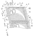
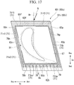
- the inner shroud 60i that is a flow passage forming plate has an inner shroud main body (plate main body) 61i and a peripheral wall 65i
- the inner shroud main body 61i has a front end surface 62f that is an end surface on the upstream side Dau, a back end surface 62b that is an end surface on the downstream side Dad, a pair of circumferential end surfaces 63 that face the opposite sides in the circumferential direction Dc, a gas path surface 64p that faces the radially outer side Dro, and an inner surface 64i that faces the radially inner side Dri.
- the end surface on the circumferential pressure side Dcp forms a pressure-side end surface 63p
- the end surface on the circumferential suction side Dcn forms a suction-side end surface 63n.
- the front end surface 62f and the back end surface 62b are roughly parallel to each other.
- the pressure-side end surface 63p and the suction-side end surface 63n are roughly parallel to each other.
- the pressure-side end surface 63p of the inner shroud 60i of one vane 50 and the suction-side end surface 63n of the inner shroud 60i of the other vane 50 face each other across a gap in the circumferential direction Dc.
- a seal plate (not shown) is disposed between the pressure-side end surface 63p of the inner shroud 60i of the one vane 50 and the suction-side end surface 63n of the inner shroud 60i of the other vane 50.
- the peripheral wall 65i has a front wall 65f and a back wall 65b facing each other in the axial direction Da, and a pair of side walls 65p, 65n facing each other in the circumferential direction Dc.
- the side wall on the circumferential pressure side Dcp forms a pressure-side wall 65p
- the side wall on the circumferential suction side Dcn forms a suction-side wall 65n.
- Each of the front wall 65f and the back wall 65b protrudes, relative to the inner shroud main body 61i, farther toward the radially inner side Dri than the pair of side walls 65p, 65n.
- the inner shroud 60i has a recess 66 (see Figure 4 and Figure 5 ) that is formed by the inner shroud main body 61i and the peripheral wall 65i and recessed toward the radially outer side Dro.
- the surface of the pressure-side wall 65p on the circumferential pressure side Dcp and the surface of the inner shroud main body 61i on the circumferential pressure side Dcp are flush with each other.
- the surface of the suction-side wall 65n on the circumferential pressure side Dcp are flush with each other.
- the surface of the suction-side wall 65n on the circumferential suction side Dcn and the surface of the inner shroud main body 61i on the circumferential suction side Dcn are flush with each other.
- the vanes 50 composing one vane row 46 of the plurality of vane rows 46 are each provided with a retainer 85 that protrudes from the pair of side walls 65p, 65n of the inner shroud 60i toward the radially inner side Dri.
- the retainer 85 is located between the front wall 65f and the back wall 65b in the axial direction Da, and is formed from the pressure-side end surface 63p to the suction-side end surface 63n.
- a pressure-side end surface of the retainer 85 is flush with the pressure-side end surface 63p of the inner shroud main body 61 i. Although this is not shown, a suction-side end surface of the retainer 85 is flush with the suction-side end surface 63n of the inner shroud main body 61i.
- the retainer 85 comes in contact with a radially outer end 6a (see Figure 5 ) on the downstream side of an inner cover 6 that is fixed to the gas turbine casing 15, and serves to support a part of the vane 50 on the radially inner side Dri onto the radially outer end 6a of the inner cover 6.
- the retainer 85 has an opening 86 (hereinafter referred to as a retainer opening 86) that is formed so as to extend therethrough in the axial direction Da.
- a space formed by the retainer opening 86 communicates with a space formed by the recess 66 of the inner shroud 60i.
- the vane 50 further includes an impingement plate 81.
- the vane 50 that is provided with the retainer 85 includes the impingement plate 81 and a seal plate 83.
- the impingement plate 81 partitions the space inside the recess 66 of the inner shroud 60i into a region on the radially inner side Dri and an inner cavity 67 that is a region on the radially outer side Dro.
- the impingement plate 81 has a plurality of through-holes 82 that are formed so as to extend therethrough in the radial direction Dr.
- the seal plate 83 covers a part of an opening of the recess 66 on the downstream side from the retainer 85.
- the seal plate 83 is located farther on the downstream side Dad than the retainer 85 and farther on the radially inner side Dri than the impingement plate 81.
- the inner shroud 60i is provided with ledges 71 that receive the impingement plate 81.
- the ledge 71 protrudes along an inner wall surface of the peripheral wall 65i, from the inner surface 64i of the inner shroud main body 61i toward the radially inner side Dri.
- the ledge 71 protrudes toward an opposite-flow-passage side (Dri) that is the inner surface side based on the gas path surface.
- the ledge 71 has a receiving surface 72 that faces the radially inner side Dri, in other words, the opposite-flow-passage side.
- the impingement plate 81 comes in contact with a contact region 72a that is a region of the receiving surface 72.
- the contact region 72a is a region of the receiving surface 72 that is separated from the inner wall surface of the peripheral wall 65i.
- the impingement plate 81 is fillet-welded to a region of the inner shroud 60i where the ledge 71 is provided, on a region of the receiving surface 72 except for the contact region 72a, in a state where the impingement plate 81 is in contact only with the contact region 72a of the receiving surface 72.
- a welded part 81w is formed between a peripheral edge of the impingement plate 81 and the receiving surface 72.
- the impingement plate 81 is butt-welded at the peripheral edge thereof to a region of the inner shroud 60i where the ledge 71 is not provided, on the inner wall surface of the peripheral wall 65i.
- a welded part 81w is formed between the peripheral edge of the impingement plate 81 and the inner wall surface of the peripheral wall 65i.
- the ledges 71 of the inner shroud 60i include a first front ledge 71f1 and a second front ledge 71f2 that are provided along an inner wall surface of the front wall 65f, a back ledge 71b that is provided along an inner wall surface of the back wall 65b, a pressure-side ledge 71 p that is provided along an inner wall surface of the pressure-side wall 65p, and a first suction-side ledge 71n1 and a second suction-side ledge 71n2 that are provided along an inner wall surface of the suction-side wall 65n.
- Each of the first front ledge 71f1 and the second front ledge 71f2 protrudes from the inner wall surface of the front wall 65f toward the back wall 65b, and protrudes from the inner surface 64i of the inner shroud main body 61i toward the radially inner side Dri.
- Each of the first front ledge 71f1 and the second front ledge 71f2 extends in a front wall extension direction in which the front wall 65f extends. This front wall extension direction is the circumferential direction Dc.
- the first front ledge 71f1 extends from the inner wall surface of the suction-side wall 65n toward the circumferential pressure side Dcp.
- the second front ledge 71f2 extends from the inner wall surface of the pressure-side wall 65p toward the circumferential suction side Dcn.
- the first front ledge 71f1 and the second front ledge 71f2 are separated from each other in the front wall extension direction.
- the ledge 71 is not provided between the first front ledge 71f1 and the second front ledge 71f2 in the front wall extension direction.
- the leading edge 52 of the vane body 51 is located between the first front ledge 71f1 and the second front ledge 71f2 in the front wall extension direction, i.e., in the region where the ledge 71 is not provided.
- the region where the ledge 71 is not provided is the region where the leading edge 52 of the vane body 51 is closest to the front wall 65f.
- the leading edge 52 is a region that is easily heated under the influence of a horseshoe vortex flow of the combustion gas G.
- a horseshoe vortex flow is a vortex flow formed by the combustion gas G as it hits a wall surface and then splits to right and left in a horseshoe shape. Accordingly, the thicknesses of the region of the front wall 65f where the ledge 71 is not provided, and of the wall or the plate having the region of the inner surface 64i where the ledge 71 is not provided are partially reduced, so that cooling of the leading edge 52 that is easy heated is enhanced.
- the back ledge 71b protrudes from the inner wall surface of the back wall 65b toward the front wall 65f, and protrudes from the inner surface 64i of the inner shroud main body 61 i toward the radially inner side Dri.
- the back ledge 71b extends from the inner wall surface of the suction-side wall 65n to the inner wall surface of the pressure-side wall 65p, in a back wall extension direction in which the back wall 65b extends. Like the front wall extension direction, this back wall extension direction is also the circumferential direction Dc.
- the pressure-side ledge 71p protrudes from the inner wall surface of the pressure-side wall 65p toward the suction-side wall 65n, and protrudes from the inner surface 64i of the inner shroud main body 61i toward the radially inner side Dri.
- the pressure-side ledge 71p extends from the inner wall surface of the front wall 65f to the inner wall surface of the back wall 65b, in a pressure-side wall extension direction in which the pressure-side wall 65p extends.
- Each of the first suction-side ledge 71n1 and the second suction-side ledge 71n2 protrudes from the inner wall surface of the suction-side wall 65n toward the pressure-side wall 65p, and protrudes from the inner surface 64i of the inner shroud main body 61i toward the radially inner side Dri.
- Each of the first suction-side ledge 71n1 and the second suction-side ledge 71n2 extends in a suction-side wall extension direction in which the suction-side wall 65n extends.
- the first suction-side ledge 71n1 extends from the inner wall surface of the front wall 65f toward the back wall 65b.
- the second suction-side ledge 71n2 extends from the inner wall surface of the back wall 65b toward the front wall 65f.
- the first suction-side ledge 71n1 and the second suction-side ledge 71n2 are separated from each other in the suction-side wall extension direction.
- the ledge 71 is not provided between the first suction-side ledge 71n1 and the second suction-side ledge 71n2 in the suction-side wall extension direction.
- a part of the suction-side surface 54 of the vane body 51 that is closest to the suction-side end surface 63n of the inner shroud main body 61i is located in the region between the first suction-side ledge 71n1 and the second suction-side ledge 71n2 in the suction-side wall extension direction, i.e., in the region where the ledge 71 is not provided.
- the region where the ledge 71 is not provided is the region where the fillet 56 formed on the outer circumference of the vane body 51 on the suction side is closest to the suction-side end surface 63n.
- the thicknesses of the suction-side wall 65n having the region of the suction-side end surface 63n where the ledge 71 is not provided, and of the wall or the plate having the region of the inner surface 64i where the ledge 71 is not provided are partially reduced, so that cooling of the fillet 56 is enhanced.
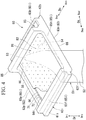
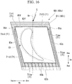
- the outer shroud 60o that is a flow passage forming plate has an outer shroud main body (plate main body) 61o and a peripheral wall 65o.
- the outer shroud main body 61o has a front end surface 62f, a back end surface 62b, a pair of circumferential end surfaces 63, a gas path surface 64p, and an inner surface 64i.
- the end surface on the circumferential pressure side Dcp forms a pressure-side end surface 63p
- the end surface on the circumferential suction side Dcn forms a suction-side end surface 63n.
- the outer shroud main body 61o has a parallelogram shape when seen from the radial direction Dr.
- the peripheral wall 65o has a front wall 65f and a back wall 65b facing each other in the axial direction Da, and a pair of side walls 65p, 65n facing each other in the circumferential direction Dc.
- the side wall on the circumferential pressure side Dcp forms a pressure-side wall 65p
- the side wall on the circumferential suction side Dcn forms a suction-side wall 65n.
- Each of the front wall 65f and the back wall 65b protrudes, relative to the outer shroud main body 61o, farther toward the radially outer side Dro than the pair of side walls 65p, 65n, and forms a hook.
- the front wall 65f and the back wall 65b forming the hooks serve to mount the vane 50 on the inner circumferential side of the turbine casing 45. Specifically, the 65f and the back wall 65b forming the hooks are mounted on the isolation ring 45c (see Figure 2 ) that constitutes a part of the turbine casing 45.
- the outer shroud 60o has a recess 66 that is formed by the outer shroud main body 61o and the peripheral wall 65o and recessed toward the radially inner side Dri.
- the surface of the pressure-side wall 65p on the circumferential pressure side Dcp and the surface of the outer shroud main body 61o on the circumferential pressure side Dcp are flush with each other.
- the surface of the suction-side wall 65n on the circumferential suction side Dcn and the surface of the outer shroud main body 61o on the circumferential suction side Dcn are flush with each other.
- the vane 50 further includes an impingement plate 81 that partitions a space inside the recess 66 of the outer shroud 60o into a region on the radially outer side Dro and an inner cavity 67 that is a region on the radially inner side Dri.
- the impingement plate 81 has a plurality of through-holes 82 that are formed so as to extend therethrough in the radial direction Dr. Part of the cooling air Ac present on the radially outer side Dro of the vane 50 flows into the inner cavity 67 through the through-holes 82 of the impingement plate 81.
- the outer shroud 60o is provided with ledges 71 that receive the impingement plate 81.
- the ledge 71 protrudes along an inner wall surface of the peripheral wall 65o, from the inner surface 64i of the outer shroud main body 61o toward the radially outer side Dro.
- the ledge 71 protrudes toward the opposite-flow-passage side (Dri) that is the side of the inner surface 64i based on the gas path surface 64p.
- the ledge 71 has a receiving surface 72 that faces the radially outer side Dro, in other words, the opposite-flow-passage side.
- this impingement plate 81 comes in contact with a contact region 72a that is a region of the receiving surface 72.
- the impingement plate 81 is fillet-welded to a region of the outer shroud 60o where the ledge 71 is provided, on a region of the receiving surface 72 except for the contact region 72a, in a state where the impingement plate 81 is in contact only with the contact region 72a of the receiving surface 72.
- a welded part 81w is formed between a peripheral edge of the impingement plate 81 and the receiving surface 72.
- the impingement plate 81 is butt-welded at the peripheral edge thereof to a region of the outer shroud 60o where the ledge 71 is not provided, on the inner wall surface of the peripheral wall 65o.
- a welded part 81w is formed between the peripheral edge of the impingement plate 81 and the inner wall surface of the peripheral wall 65o.
- the ledges 71 of the outer shroud 60o include a first front ledge 71f1 and a second front ledge 71 f2 that are provided along an inner wall surface of the front wall 65f, a back ledge 71b that is provided along an inner wall surface of the back wall 65b, a pressure-side ledge 71p that is provided along an inner wall surface of the pressure-side wall 65p, and a first suction-side ledge 71n1 and a second suction-side ledge 71n2 that are provided along an inner wall surface of the suction-side wall 65n.
- Each of the first front ledge 71f1 and the second front ledge 71f2 protrudes from the inner wall surface of the front wall 65f toward the back wall 65b, and protrudes from the inner surface 64i of the outer shroud main body 61o toward the radially outer side Dro.
- Each of the first front ledge 71f1 and the second front ledge 71f2 extends in a front wall extension direction in which the front wall 65f extends. This front wall extension direction is the circumferential direction Dc.
- the first front ledge 71f1 extends from the inner wall surface of the suction-side wall 65n toward the circumferential pressure side Dcp.
- the second front ledge 71f2 extends from the inner wall surface of the pressure-side wall 65p toward the circumferential suction side Dcn.
- the first front ledge 71f1 and the second front ledge 71f2 are separated from each other in the front wall extension direction.
- the ledge 71 is not provided between the first front ledge 71f1 and the second front ledge 71f2 in the front wall extension direction.
- the leading edge 52 of the vane body 51 is located between the first front ledge 71f1 and the second front ledge 71f2 in the front wall extension direction, i.e., in the region where the ledge 71 is not provided.
- the region where the ledge 71 is not provided is the region where the leading edge 52 of the vane body 51 is closest to the front wall 65f.
- the leading edge 52 is a region that is easily heated under the influence of a horseshoe vortex flow of the combustion gas G. Accordingly, the thicknesses of the region of the front wall 65f where the ledge 71 is not provided, and of the wall or the plate having the region of the inner surface 64i where the ledge 71 is not provided are partially reduced, so that cooling of the leading edge 52 that is easily heated is enhanced.
- the back ledge 71b protrudes from the inner wall surface of the back wall 65b toward the front wall 65f, and protrudes from the inner surface 64i of the outer shroud main body 61o toward the radially outer side Dro.
- the back ledge 71b extends from the inner wall surface of the suction-side wall 65n to the inner wall surface of the pressure-side wall 65p, in a back wall extension direction in which the back wall 65b extends.
- This back wall extension direction is the circumferential direction Dc.
- the pressure-side ledge 71p protrudes from the inner wall surface of the pressure-side wall 65p toward the suction-side wall 65n, and protrudes from the inner surface 64i of the outer shroud main body 61o toward the radially outer side Dro.
- the pressure-side ledge 71p extends from the inner wall surface of the front wall 65f to the inner wall surface of the back wall 65b, in a pressure-side wall extension direction in which the pressure-side wall 65p extends.
- Each of the first suction-side ledge 71nl and the second suction-side ledge 71n2 protrudes from the inner wall surface of the suction-side wall 65n toward the pressure-side wall 65p, and protrudes from the inner surface 64i of the outer shroud main body 61o toward the radially outer side Dro.
- Each of the first suction-side ledge 71n1 and the second suction-side ledge 71n2 extends in a suction-side wall extension direction in which the suction-side wall 65n extends.
- the first suction-side ledge 71n1 extends from the inner wall surface of the front wall 65f toward the back wall 65b.
- the second suction-side ledge 71n2 extends from the inner wall surface of the back wall 65b toward the front wall 65f.
- the first suction-side ledge 71n1 and the second suction-side ledge 71n2 are separated from each other in the suction-side wall extension direction.
- the ledge 71 is not provided between the first suction-side ledge 71n1 and the second suction-side ledge 71n2 in the suction-side wall extension direction.
- a part of the suction-side surface of the vane body 51 that is closest to the suction-side end surface 63n of the outer shroud main body 61o is located between the first suction-side ledge 71n1 and the second suction-side ledge 71n2 in the suction-side wall extension direction, i.e., in the region where the ledge 71 is not provided.
- the region where the ledge 71 is not provided is the region where the fillet 56 formed on the outer circumference of the vane body 51 on the suction side is closest to the suction-side end surface 63n.
- the thicknesses of the suction-side wall 65n having the region of the suction-side end surface 63n where the ledge 71 is not provided, and of the wall or the plate having the region of the inner surface 64i where the ledge 71 is not provided are partially reduced, so that cooling of the fillet 56 is enhanced.
- a plurality of vane air passages 75 extending in the radial direction Dr are formed inside the vane body 51, the outer shroud 60o, and the inner shroud 60i.
- Each vane air passage 75 is formed continuously from the outer shroud 60o through the vane body 51 to the inner shroud 60i.
- the plurality of vane air passages 75 are arrayed along the chord of the vane body 51. Some of adjacent vane air passages 75 communicate with each other at a part on the radially outer side Dro or at a part on the radially inner side Dri.
- One of the plurality of vane air passages 75 is open on the radially outer side Dro.
- a plurality of vane air passages 75 are closed on the radially outer side Dro.
- a part of the vane air passage that defines the radially outer side Dro protrudes farther toward the radially outer side Dro than the inner surface 64i of the outer shroud main body 61o, and thus forms an outer lip 76o.
- a part of the vane air passage 75 that defines the radially inner side Dri protrudes farther toward the radially inner side Dri than the inner surface 64i of the inner shroud main body 61i, and thus forms an inner lip 76i.
- vane air passage 75 there are four vane air passages 75. Of these four vane air passages 75, the vane air passage 75 located farthest on the upstream side Dau will be referred to as a first vane air passage 75a. Subsequently, a second vane air passage 75b, a third vane air passage 75c, and a fourth vane air passage 75d are assumed to be arrayed in the order mentioned, on the downstream side based on the first vane air passage 75a. A part of the second vane air passage 75b on the radially inner side Dri communicates with a part of the third vane air passage 75c on the radially inner side Dri. A part of the third air passage on the radially outer side Dro communicates with a part of the fourth vane air passage 75d on the radially outer side Dro.
- Ends of the outer lips 76o of the third vane air passage 75c and the fourth vane air passage 75d on the radially outer side Dro protrude farther toward the radially outer side Dro than the inner surface 64i of the outer shroud main body 61o, but are located farther on the radially inner side Dri than the impingement plate 81 of the outer shroud 60o.
- the ends of the outer lips 76o of the third vane air passage 75c and the fourth vane air passage 75d on the radially outer side Dro are closed.
- Ends of the inner lips 76i of the first vane air passage 75a, the second vane air passage 75b, the third vane air passage 75c, and the fourth vane air passage 75d on the radially inner side Dri protrude farther toward the radially inner side Dri than the inner surface 64i of the inner shroud main body 61i, but are located farther on the radially outer side Dro than the impingement plate 81 of the inner shroud 60i.
- the ends of the inner lips 76i of the second vane air passage 75b and the third vane air passage 75c on the radially inner side Dri are closed.
- each of the ends of the inner lips 76i of the first vane air passage 75a and the fourth vane air passage 75d on the radially inner side Dri is closed with a cap 84.
- the cap 84 is joined by welding to the end of the inner lip 76i on the radially inner side Dri.
- the leading edge 52 and the trailing edge 53 of the vane body 51 have a plurality of vane surface blow-out passages 77 that are formed so as to extend therethrough from the vane air passage 75 to the combustion gas flow passage 49.
- the vane body 51 is cooled in the process of the cooling air Ac flowing through the vane air passages 75.
- the cooling air Ac having flowed into the vane air passage 75 flows out of the vane surface blow-out passages 77 into the combustion gas flow passage 49.
- the leading edge 52 and the trailing edge 53 of the vane body 51 are cooled in the process of the cooling air Ac flowing out of the vane surface blow-out passages 77.
- part of the cooling air Ac having flowed out of the vane surface blow-out passages 77 into the combustion gas flow passage 49 serves also as film-cooling air by partially covering the surface of the vane body 51.
- the pressure-side wall 65p of the outer shroud 60o has a pressure-side passage 78p that is formed so as to extend along the pressure-side end surface 63p in a direction having a component of the axial direction Da.
- the suction-side wall 65n of the outer shroud 60o has a suction-side passage 78n that is formed so as to extend along the suction-side end surface 63n in a direction having a component of the axial direction Da.
- Each of the pressure-side passage 78p and the suction-side passage 78n communicates at an upstream end thereof with the inner cavity 67.
- Each of the pressure-side passage 78p and the suction-side passage 78n opens at a downstream end thereof in the back end surface 62b of the outer shroud main body 61o.
- the outer shroud main body 61o and the back wall 65b have a plurality of back end surface blow-out passages 79 that are formed so as to extend across the outer shroud main body 61o and the back wall 65b, from the inner cavity 67 toward the back end surface 62b of the outer shroud main body 61o.
- the plurality of back end surface blow-out passages 79 communicate at upstream ends thereof with the inner cavity 67. Downstream ends of the back end surface blow-out passages 79 are open in the back end surface 62b of the outer shroud main body 61o.
- the pressure-side wall 65p of the inner shroud 60i has a pressure-side passage 78p that is formed so as to extend along the pressure-side end surface 63p in a direction having a component of the axial direction Da.
- the suction-side wall 65n of the inner shroud 60i has a suction-side passage 78n that is formed so as to extend along the suction-side end surface 63n in a direction having a component of the axial direction Da.
- Each of the pressure-side passage 78p and the suction-side passage 78n communicates at an upstream end thereof with the inner cavity 67.
- Each of the pressure-side passage 78p and the suction-side passage 78n is open at a downstream end thereof in the back end surface 62b of the inner shroud main body 61 i.
- the inner shroud main body 61i and the back wall 65b have a plurality of back end surface blow-out passages 79 that are formed so as to extend across the inner shroud main body 61i and the back wall 65b, from the inner cavity 67 toward the back end surface 62b of the inner shroud main body 61i.
- the plurality of back end surface blow-out passages 79 communicate at upstream ends thereof with the inner cavity 67. Downstream ends of the back end surface blow-out passages 79 are open in the back end surface 62b of the inner shroud main body 61i.
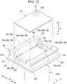
- the ring segment 90 that is a flow passage forming plate has a ring segment main body (plate main body) 91 and a peripheral wall 95.
- the ring segment main body 91 has a front end surface 92f, a back end surface 92b that is an end surface on the downstream side Dad, a pair of circumferential end surfaces 93, a gas path surface 94p, and an inner surface 94i.
- the ring segment main body 91 has a rectangular shape or a square shape.
- the peripheral wall 95 includes a front wall 95f and a back wall 95b facing each other in the axial direction Da, and a pair of side walls 95s facing each other in the circumferential direction Dc.
- Each of the front wall 95f and the back wall 95b protrudes, relative to the ring segment main body 91, farther toward the radially outer side Dro than the pair of side walls 95s, and forms a hook.
- the front wall 95f and the back wall 95b forming the hooks serve to mount the vane 50 on the inner circumferential side of the turbine casing 45.
- the front wall 95f and the back wall 95b forming the hooks are mounted on the isolation ring 45c (see Figure 2 ) that constitutes a part of the turbine casing 45.
- the ring segment 90 has a recess 96 that is formed by the ring segment main body 91 and the peripheral wall 95 and recessed toward the radially inner side Dri.
- the ring segment 90 is provided with an impingement plate 101 that partitions a space inside the recess 96 into a region on the radially outer side Dro and an inner cavity 97 that is a region on the radially inner side Dri.
- the impingement plate 101 has a plurality of through-holes 102 that are formed so as to extend therethrouth in the radial direction Dr. Part of the cooling air Ac present on the radially outer side Dro of the ring segment 90 flows into the inner cavity 97 through the through-holes 102 of the impingement plate 101.
- the ring segment 90 has a side end passage that leads from the inner cavity 97 to a space on an outer side of a side end surface, and a back end passage that leads from the inner cavity 97 to a space on the downstream side of the back end surface.
- the cooling air Ac having flowed into the inner cavity 97 flows through the side end passage, the back end passage, etc. to the outside
- the ring segment 90 is provided with ledges 98 that receive the impingement plate 101.
- the ledge 98 protrudes along an inner wall surface of the peripheral wall 95, from the inner surface 94i of the ring segment main body 91 toward the radially outer side Dro.
- the ledge 98 protrudes toward the opposite-flow-passage side (Dro) that is the side of the inner surface 94i based on the gas path surface 94p.
- the ledge 98 has a receiving surface 99 facing the radially outer side Dro.
- the ledges 98 include a front ledge 98f that is provided along an inner wall surface of the front wall 95f, a back ledge (not shown) that is provided along an inner wall surface of the back wall 95b, and side ledges 98s that are provided respectively along inner wall surfaces of the pair of side walls 95s
- Each of the front ledge 98f and the back ledge includes a first ledge 98x and a second ledge 98y.
- Each of the first ledge 98x and the second ledge 98y of the front ledge 98f protrudes from the inner wall surface of the front wall 95f toward the back wall 95b, and protrudes from the inner surface 94i of the ring segment main body 91 toward the radially outer side Dro.
- Each of the first ledge 98x and the second ledge 98y extends in a front wall extension direction in which the front wall 95f extends. This front wall extension direction is the circumferential direction Dc.
- the first ledge 98x of the front ledge 98f extends from the inner wall surface of the one side wall 95s toward the other side wall 95s.
- the second ledge 98y of the front ledge 98f extends from the inner wall surface of the other side wall 95s toward the one side wall 95s.
- the first ledge 98x and the second ledge 98y of the front ledge 98f are separated from each other in the front wall extension direction.
- the ledge 98 is not provided between the first ledge 98x and the second ledge 98y of the front ledge 98f in the front wall extension direction.
- the first ledge of the back ledge (not shown) has the same configuration as the first ledge 98x of the front ledge 98f, and the second ledge of the back ledge has the same configuration as the second ledge 98y of the front ledge 98f.
- each of the first ledge and the second ledge of the back ledge protrudes from the inner wall surface of the back wall 95b toward the front wall 95f, and protrudes from the inner surface 94i of the ring segment main body 91 toward the radially outer side Dro.
- Each of the first ledge and the second ledge of the back ledge extends in a back wall extension direction in which the back wall 95b extends. This back wall extension direction is the circumferential direction Dc.
- the first ledge of the back ledge extends from the inner wall surface of the one side wall 95s toward the other side wall 95s.
- the second ledge of the back ledge extends from the inner all surface of the other side wall 95s toward the one side wall 95s.
- the first ledge and the second ledge of the back ledge are separated from each other in the back wall extension direction.
- the ledge 98 is not provided between the first ledge and the second ledge in the back wall in the back wall extension direction.
- Each of the pair of side ledges 98s includes a first ledge 98x and a second ledge 98y.
- the first ledge 98x of one side ledge 98s of the pair of side ledges 98s and the first ledge 98x of the other side ledge 98s have basically the same configuration.
- the second ledge 98y of one side ledge 98s of the pair of side ledges 98s and the second ledge 98y of the other side ledge 98s have basically the same configuration.
- Each of the first ledge 98x and the second ledge 98y of one side ledge 98s protrudes from the inner wall surface of one side wall 95s toward the other side wall 95s, and protrudes from the inner surface 94i of the ring segment main body 91 toward the radially outer side Dro.
- Each of the first ledge 98x and the second ledge 98y extends in a side wall extension direction in which the side wall 95s extends.
- the first ledge 98x extends from the inner wall surface of the front wall 95f toward the back wall 95b.
- the second ledge 98y extends from the inner wall surface of the back wall 95b toward the front wall 95f.
- the first ledge 98x and the second ledge 98y are separated from each other in the side wall extension direction.
- the ledge 98 is not provided between the first ledge 98x and the second ledge 98y in the side wall extension direction.
- the impingement plate 101 comes in contact with a contact region that is a region of the receiving surface 99 of the ledge 98.
- the impingement plate 101 is fillet-welded to a region of the ring segment 90 where the ledge 98 is provided, on a region of the receiving surface 99 except for the contact region, in a state where the impingement plate 101 is in contact only with the contact region of the receiving surface 99.
- a welded part is formed between a peripheral edge of the impingement plate 101 and the receiving surface 99.
- the impingement plate 101 is butt-welded at a peripheral edge thereof to the region of the reign segment 90 where the ledge 98 is not provided, on the inner wall surface of the peripheral wall 95.
- a welded part is formed between the peripheral edge of the impingement plate 101 and the inner wall surface of the peripheral wall 95.
- Part of the cooling air Ac present on the radially outer side Dro of the vane 50 is supplied from inside the intermediate casing 14. This part of the cooling air Ac flows into the inner cavity 67 of the outer shroud 60o through the through-holes 82 formed in the impingement plate 81 of the outer shroud 60o. In this process, the cooling air Ac impinges on a surface of the member forming the inner cavity 67, specifically, the inner surface 64i of the outer shroud main body 61o, and impingement-cools the inner surface 64i. As a result, the gas path surface 64p facing the inner surface 64i is cooled by the cooling air Ac.
- the cooling air Ac having flowed into the pressure-side passage 78p cools a part of the gas path surface 64p of the outer shroud main body 61o on the circumferential pressure side Dcp, and the pressure-side end surface 63p of the outer shroud main body 61o in the process of passing through the pressure-side passage 78p.
- This cooling air Ac flows out from the back end surface 62b of the outer shroud main body 61o toward the downstream side.
- the cooling air Ac having flowed into the suction-side passage 78n cools a part of the gas path surface 64p of the outer shroud main body 61o on the circumferential suction side Dcn, and the suction-side end surface 63n of the outer shroud main body 61o in the process of passing through the suction-side passage 78n.
- This cooling air Ac flows out from the back end surface 62b of the outer shroud main body 61o toward the downstream side.
- Another part of the cooling air Ac having flowed into the inner cavity 67 flows into the back end surface blow-out passages 79 communicating with the inner cavity 67.
- the cooling air Ac having flowed into the back end surface blow-out passages 79 cools a part of the gas path surface 64p of the outer shroud main body 61o on the downstream side Dad in the process of passing through the back end surface blow-out passages 79.
- This cooling air Ac flows out from the back end surface 62b of the outer shroud main body 61o toward the downstream side.
- Another part of the cooling air Ac present on the radially outer side Dro of the vane 50 flows into the vane air passage 75 of the plurality of vane air passages 75 that is open at the end on the radially outer side Dro.
- the cooling air Ac having flowed into the vane air passage 75 convectively cools the vane body 51 in the process of flowing through the vane air passage 75.
- the cooling air Ac having flowed into the vane air passage 75 flows out into the combustion gas flow passage 49 through the vane surface blow-out passages 77 communicating with this vane air passage 75.
- the leading edge 52 and the trailing edge 53 of the vane body 51 are cooled in the process of the cooling air Ac flowing out of the vane surface blow-out passages 77.
- part of the cooling air Ac having flowed out of the vane surface blow-out passages 77 into the combustion gas flow passage 49 film-cools the vane body 51 by partially covering the surface of the vane body 51.
- Part of the cooling air Ac present on the radially inner side Dri of the vane 50 is supplied from inside the intermediate casing 14. This part of the cooling air Ac flows into the inner cavity 67 of the inner shroud 60i through the through-holes 82 formed in the impingement plate 81 of the inner shroud 60i. In this process, the cooling air Ac impinges on a surface of the member forming the inner cavity 67, specifically, the inner surface 64i of the inner shroud main body 61i, and impingement-cools the inner surface 64i. As a result, the gas path surface 64p facing the inner surface 64i is cooled by the cooling air Ac.
- the cooling air Ac having flowed into the pressure-side passage 78p cools a part of the gas path surface 64p of the inner shroud main body 61i on the circumferential pressure side Dcp, and the pressure-side end surface 63p of the inner shroud main body 61i in the process of passing through the pressure-side passage 78p.
- This cooling air Ac flows out from the back end surface 62b of the inner shroud main body 61i toward the downstream side.
- the cooling air Ac having flowed into the suction-side passage 78n cools a part of the gas path surface 64p of the inner shroud main body 61 i on the circumferential suction side Dcn, and the suction-side end surface 63n of the inner shroud main body 61 i in the process of passing through the suction-side passage 78n.
- This cooling air Ac flows out from the back end surface 62b of the inner shroud main body 61i toward the downstream side.
- Another part of the cooling air Ac having flowed into the inner cavity 67 flows into the back end surface blow-out passages 79 communicating with the inner cavity 67.
- the cooling air Ac having flowed into the back end surface blow-out passages 79 cools a part of the gas path surface 64p of the inner shroud main body 61 i on the downstream side Dad in the process of passing through the back end surface blow-out passages 79.
- This cooling air Ac flows out from the back end surface 62b of the inner shroud main body 61 i toward the downstream side.
- the ledges 71 that receive the impingement plates 81 of the inner shroud 60i and the outer shroud 60o in this embodiment are formed not along the entire inner wall surfaces of the peripheral walls 65i, 65o of the shrouds 60i, 60o, but are formed along only parts of the inner wall surfaces of the peripheral walls 65i, 65o.
- the ledge 71 is not provided in parts of the inner wall surfaces of the peripheral walls 65i, 65o.
- the through-holes 82 of the impingement plates 81 can be formed close to the inner wall surfaces of the peripheral walls 65i, 65o so that the inner wall surfaces of the peripheral walls 65i, 65o, and moreover parts of the inner surfaces 64i of the shroud main bodies 61 i, 61o close to the inner wall surfaces of the peripheral walls 65i, 65o can be effectively cooled with the cooling air Ac flowing through these through-holes 82 into the inner cavities 67.
- outer wall surfaces of the peripheral walls 65i, 65o, and moreover the parts of the gas path surfaces 64p along the peripheral walls 65i, 65o can be effectively cooled.
- the walls between the inner cavity 67 and an outer space on the opposite side based on these parts have a smaller thickness, so that the heat capacity of these parts can be reduced compared with the parts where the ledge 71 is provided.
- the shrouds 60i, 60o can be effectively cooled in this embodiment.
- the high-temperature combustion gas G hits the leading edge 52 of the vane body 51 of the vane 50.
- the coefficient of heat transfer between the leading edge 52 and the combustion gas G increases, and the leading edge 52 is more easily heated by the combustion gas G than the pressure-side surface 55 or the suction-side surface 4 of the vane body 51.
- regions of the gas path surfaces 64p of the shrouds 60i, 60o in the vicinity of the leading edge 52 of the vane body 51 are also easily heated by the combustion gas G.
- the distance between the leading edge 52 of the vane body 51 and an inner circumferential surface of the front wall 65f in the axial direction Da is short.
- the ledge 71 is not provided in the region where the leading edge 52 of the vane body 51 is located in the front wall extension direction in which the front wall 65f extends.
- the regions of the shrouds 60i, 60o that are easily heated and not easily cooled can be cooled in this embodiment.
- the distance in the circumferential direction Dc between a part of the suction-side surface 54 of the vane body 51 that is located farthest on the circumferential suction side Dcn and the inner wall surface of the suction-side wall 65n is also short.
- the through-holes 82 of the impingement plate 81 in this space, and it is difficult to cool this space with the cooling air Ac.
- the ledge 71 is not provided in the region of the suction-side surface of the vane body 51 that is located farthest on the circumferential suction side Dcn in the suction-side wall extension direction in which the suction-side wall 65n extends.
- the regions of the shrouds 60i, 60o that are not easily cooled can be cooled in this embodiment.
- the ledges 98 that receive the impingement plate 101 of the ring segment 90 of this embodiment are also formed not along the entire inner wall surface of the peripheral wall 95 of the ring segment 90, but is formed along only a part of the inner wall surface of the peripheral wall 95.
- the ledge 98 is not provided in a part of the inner wall surface of the peripheral wall 95.
- the through-holes 102 of the impingement plate 101 can be formed close to the inner wall surface of the peripheral wall 95 so that, as with the shrouds 60i, 60o described above, the ring segment 90 can be effectively cooled with the cooling air Ac flowing through these through-holes 102 into the inner cavity 97.
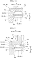
- Figure 18(A) shows the embodiment in which the impingement plate 81 is mounted on the ledges 71.
- Figure 18(B) and Figure 18(C) respectively show Comparative Examples 1 and 2 in which the ledge is not provided and the impingement plate 81 is mounted directly on the inner wall surfaces of the peripheral walls 65i, 65o.
- the distance between the inner surface 64i of the shroud 60i or 60o and the impingement plate 81 can be set to the distance H1 with ease and high accuracy along the entire inner cavity 67, by setting the distance between the inner surface 64i of the shroud 60i or 60o and the receiving surface 72 of the ledge 71 substantially to the distance HI.
- the impingement plate 81 is fillet-welded to the region of the shroud 60i or 60o where the ledge 71 is provided, on the region of the receiving surface 72 except for the contact region 72a, in the state where the impingement plate 81 is in contact only with the contact region 72a of the receiving surface 72.
- the welded part 81w formed by this fillet welding is formed at a region of the receiving surface 72, on the side of the peripheral wall 65i or 65o that is the opposite side of the contact region 72a from an end on the side of the inner cavity 67.
- the through-holes 82 formed in the impingement plate 81 can be formed at any positions except for the region of the impingement plate 81 that comes in contact with the receiving surface 72 of the ledge 71.
- the through-holes 82 can be formed at positions in the vicinity of the region of the impingement plate 81 that comes in contact with the receiving surface 72 of the ledge 71, in other words, at positions in the vicinity of the inner wall surface of the ledge 71 facing the inner cavity 67.
- the distances between the inner surfaces 64i of the shrouds 60i, 60o and the impingement plates 81 can be set to the distance H1 with high accuracy along the entire inner cavities 67, so that the inner surfaces 64i of the shrouds 60i, 60o can be effectively impingement-cooled.
- the through-holes 82 can be formed at positions of the impingement plates 81 in the vicinity of the inner wall surfaces of the ledges 71 facing the inner cavities 67, and the impingement plates 81 are welded at positions farther on the side of the inner wall surfaces of the peripheral walls 65i, 65o than the inner wall surfaces of the ledges 71.
- the inner wall surfaces of the ledges 71 can also be effectively cooled. Furthermore, in this embodiment, it is possible to easily fix the impingement plates 81 at such positions that the distances from the inner surfaces 64i of the shrouds 60i, 60o are the appropriate distance H1, by welding the impingement plates 81 to the shrouds 60i, 60o in the state where the impingement plates 81 are in contact with the receiving surfaces 72 of the ledges 71.
- An impingement plate 81x in Comparative Example 1 shown in Figure 18(B) has an impingement plate main body 81xa and a flange plate 81xb that is formed on an outer peripheral edge of the impingement plate main body 81xa.
- the impingement plate main body 81xa faces the inner surface 64i of the shroud 60i or 60o.
- the flange plate 81xb extends from the outer peripheral edge of the impingement plate main body 81xa in a direction substantially perpendicular to a direction in which the impingement plate main body 81xa extends.
- the impingement plate 81x is formed by bending an outer peripheral portion of a plate at a substantially right angle.
- the impingement plate 81x is fixed to the shroud 60i or 60o by being fillet-welded at a leading end of the flange plate 81xb to the inner wall surface of the peripheral wall 65i or 65o, in a state where the flange plate 81xb is in contact with the inner wall surface of the peripheral wall 65i or 65o.
- a welded part 81xw is formed between the leading end of the flange plate 81xb and the inner wall surface of the peripheral wall 65i or 65o.
- Comparative Example 1 it is difficult to set the distance between the inner surface 64i of the shroud 60i or 60o and the impingement plate 81x to the appropriate distance HI. In Comparative Example 1, it is difficult to maintain the distance from the inner surface 64i of the shroud 60i or 60o at the appropriate distance HI during welding.
- a jig such as a spacer
- the jig remaining inside the inner cavity 67 after the impingement plate 81 x is welded cannot be taken out.
- it is necessary to provide a take-out opening in the impingement plate 81x which makes the structure of the impingement plate 81x complicated.
- another possible method is to hold the impingement plate 81x with some jig so that the distance from the inner surface 64i of the shroud 60i or 60o to the leading end of the flange plate 81xb is a distance H2, and weld the impingement plate 81x to the shroud 60i or 60o in this state.
- This method also requires using a jig.
- the leading end of the flange plate 81xb needs to be finished flat by machining.
- the through-holes 82 cannot be formed in the flange plate 81xb of the impingement plate 81x that comes in contact with the inner wall surface of the peripheral wall 65i or 65o, or at positions of the impingement plate main body 81xa in the vicinity of the flange plate 81xb, which is disadvantageous in cooling the inner wall surface of the peripheral wall 65i or 65o.
- producing the impingement plate 81x requires bending the outer peripheral portion of a plate at a substantially right angle.
- an impingement plate 81y of Comparative Example 2 shown in Figure 18(C) is produced by forming the through-holes 82 in a flat plate.
- the impingement plate 81y is fixed to the shroud 60i or 60o by being welded at an outer peripheral edge thereof to the inner wall surface of the peripheral wall 65i or 65o, in a state where the outer peripheral edge of the impingement plate 81 is butted against the inner wall surface of the peripheral wall 65i or 65o.
- a welded part 81yw is formed between the outer peripheral edge of the impingement plate 81y and the inner wall surface of the peripheral wall 65i or 65o.
- Comparative Example 2 As in Comparative Example 1, it is difficult to set the distance between the inner surface 64i of the shroud 60i or 60o and the impingement plate 81y to the appropriate distance H1. Moreover, in Comparative Example 2, the welded part 81yw is formed between the outer peripheral edge of the impingement plate 8ly and the inner wall surface of the peripheral wall 65i or 65o. Accordingly, the through-holes 82 cannot be formed in a part of the impingement plate 81y close to the outer peripheral edge, which is disadvantageous in cooling the inner wall surface of the peripheral wall 65i or 65o.
- the structure of the embodiment has advantages over the structures of Comparative Examples 1 and 2 in terms of the ease of fixation of the impingement plate 81 and the accuracy of positioning of the impingement plate 81. Moreover, the structure of the embodiment has advantages over the structures of Comparative Examples 1 and 2 in terms of cooling of the inner wall surfaces, too.
- the ledge 71 is not provided along one wall constituting a part of the peripheral wall 65i or 65o, it is possible to fix the impingement plate 81 to the shroud 60i or 60o with ease and high accuracy, if the ledge 71 is provided along other walls that are joined to the wall at that position.
- the ledge 71 is not provided along the front wall 65f that constitutes a part of the peripheral wall 65i or 65o, it is possible to fix the impingement plate 81 to the shroud 60i or 60o with ease and high accuracy, if the ledge 71 is provided along the side walls 65p, 65n that are joined to the front wall 65f.
- the vane main body is formed (S1: main body forming step).
- the vane main body has a part among the parts composing the vane 50 that does not include accessories such as the impingement plate 81.
- the accessories are manufactured (S7: accessory manufacturing step).
- the accessories include, other than the impingement plate 81 mentioned above, the cap 84 that closes the end opening of the vane air passage 75, an insert that is inserted as necessary into the vane air passage 75, and the seal plate 83.
- an intermediate product of the vane main body is formed by casting (S2: intermediate product forming step).
- S2 intermediate product forming step
- a casting mold forming step (S3) and an intermediate product casting step (S4) are performed.
- a casting mold having an internal space matching the outer shape of the intermediate product, and as necessary, a vane air passage core having an outer shape matching the shape of the vane air passage 75 are formed.
- the vane air passage core is made of ceramic.
- the vane air passage core is disposed inside the casting mold, and molten metal is poured into the casting mold.
- the molten metal is a melt of nickel-base alloy etc. having high heat resistance.
- the ceramic vane air passage core is melted in an alkaline solution.
- This intermediate product has parts that constitute the vane body 51 and the shrouds 60i, 60o as the flow passage forming plates.
- this intermediate product has the ledges 71 for receiving the impingement plate 81, formed along the entire inner wall surfaces of the peripheral walls 65i, 65o of the shrouds 60i, 60o.
- a part of the ledge 71 of each of the shrouds 60i, 60o is removed (S5: part removing step).
- a part of the ledge 71 is removed by an existing method, for example, machining, electric discharge machining, or electro-chemical machining.
- this part removing step (S5) of the ledge 71 extending in the front wall extension direction along the front wall 65f of each of the shrouds 60i, 60o, an intermediate part of the ledge 71 in the front wall extension direction is removed.
- the first front ledge 71f1 and the second front ledge 71f2 separated from each other in the front wall extension direction are formed in each of the shrouds 60i, 60o.
- finishing step for example, an outer surface of the intermediate product is polished.
- flow passages that are not yet formed in the intermediate product are formed in the vane body 51 and the shrouds 60i, 60o of the intermediate product by an existing method such as machining or electric discharge machining.
- a thermal barrier coating is applied to the outer surface of the intermediate product as necessary.
- the accessories are installed to the vane main body (S8: installation step).
- the cap 84 for closing the end opening of the vane air passage 75, the insert, etc. are mounted to the vane main body.
- the impingement plate 81, the seal plate 83, etc. are mounted to the vane main body.
- the vane 50 of this embodiment can also be manufactured without performing the above manufacturing method.
- the intermediate product forming step (S2) an intermediate product is formed in which the ledge 71 is formed along only a part of each of the inner wall surfaces of the peripheral walls 65i, 65o of the shrouds 60i, 60o.
- the casting mold forming step (S3) a casting mold having an internal space matching the outer shape of this intermediate product is formed.
- the part removing step (S5) is omitted if the intermediate product having the ledge 71 formed along only a part of each of the inner wall surfaces of the peripheral walls 65i 65o of the shrouds 60i, 60o is formed.
- the ring segment 90 as the flow passage forming member assembly can also be manufactured by the same procedure. Specifically, the ring segment 90 can be manufactured by performing the main body forming step (S2), the part removing step (S5), and the finishing step (S6). When the ring segment 90 is completed, the impingement plate 101 is mounted to the ring segment 90 to complete the ring segment having the impingement plate (flow passage forming member assembly).
- the vane to be modified here is a vane having the ledge 71 formed along the entire inner wall surfaces of the peripheral walls 65i, 65o of the shrouds 60i, 60o.
- the vane to be modified may be an unused vane or a used vane.
- the vane main body to be modified is modified (S10: modification step).
- S10 modification step
- accessories are manufactured as necessary (S7: accessory manufacturing step).
- modification step (S10) first, a part of the ledge 71 of each of the shrouds 60i, 60o of the vane main body to be modified is removed (S15: part removing step).
- the contents of the process in this part removing step (S15) are basically the same as those in the part removing step (S5) of the manufacturing method.
- a finishing step (S16) similar to the finishing step (S6) of the manufacturing method is performed as necessary.
- this finishing step (S16) is not required, for example, when an unused vane is modified.
- the thickness of the inner shroud main body 61i is reduced from the thickness of the inner shroud main body 61 i of the above embodiment.
- the thickness of the inner shroud main body 61i refers to the interval between the gas path surface 64p and the inner surface 64i of the inner shroud main body 61i.
- a thinning process for reducing the thickness of the inner shroud main body 61i is performed in the part removing step of the manufacturing method and the modification method of the above embodiment.
- the side of the inner surface 64i of the inner shroud main body 61i is processed by an existing method, for example, machining, electric discharge machining, or electro-chemical machining, as in removing a part of the ledge 71.
- the distance between the inner surface 64i of the inner shroud main body 61i and the receiving surface 72 of the ledge 71 becomes larger after processing than before processing. It is therefore preferable to perform a process for reducing the height of the ledge 71 along with the thinning process of the inner shroud main body 61i.
- the impingement plate 81 is bent so that a part of the impingement plate 81 that faces the cap 84, in other words, a part thereof that faces the inner lip 76i is shifted in a thickness direction of the impingement plate 81 relative to a part of the impingement plate 81 that faces the inner surface 64i after processing.
- an impingement plate 81a is used of which a part facing the inner lip 76i of the vane air passage 75 is shifted in the thickness direction relative to the part facing the inner surface 64i. If the impingement plate 81a is used, the distance between the cap 84 etc. and the impingement plate 81a can be set to the appropriate distance H3.
- the heat capacity of the inner shroud main body 61i is reduced, so that the inner shroud main body 61i can be effectively cooled with the cooling air Ac.
- this modified example is an example of thinning the inner shroud main body 61i, the outer shroud main body 61o or the ring segment main body 91 of the above embodiment may also be thinned in the same manner.
- each of the back ledges 71b extending along the back walls 65b of the shrouds 60i, 60o extends from the suction-side wall 65n of the shroud 60i or 60o to the pressure-side wall 65p thereof.
- a back ledge 71ba extending along the back wall 65b of the shroud 60i or 60o may extend from the suction-side wall 65n of the shroud 60i or 60o only to a point short of the pressure-side wall 65p.
- the ledge 71 does not need to extend from one wall to the other wall of a pair of walls facing each other.
- the number of the ledges 71 provided along one wall constituting a part of the peripheral wall 65i or 65o is two at the most. Moreover, both the two ledges 71 extend from other walls joined to one wall.
- the first front ledge 71f1 and the second front ledge 71f2 provided along the front wall 65f extend respectively from the side walls 65n, 65p joined to the front wall 65f.
- three or more ledges 71 may be provided along one wall constituting a part of the peripheral wall 65i or 65o. Moreover, the ledges 71 do not need to extend from other walls joined to one wall.
- a region where the ledge 71 is not provided is appropriately provided, this region where the ledge 71 is not provided can be more effectively cooled with the cooling air Ac.
- a region of the fillet 56 formed on the outer circumference of the vane body 51 that is located in the vicinity of the back wall 65b is a region where the ledge 71 is not provided.
- cooling of the region of the fillet 56 in the vicinity of the back wall 65b is enhanced.
- the plurality of back end surface blow-out passages 79 that extend from the inner cavity 67 toward the back end surface 62b of the inner shroud main body 61i are formed.
- the plurality of back end surface blow-out passages 79 communicate at the upstream ends with the inner cavity 67.
- a back-side passage 78b that provides communication between the suction-side passage 78n and the pressure-side passage 78p may be formed in the back wall 65b, and the plurality of back end surface blow-out passages 79 extending from the back-side passage 78b toward the back end surface 62b of the shroud main body 61 i or 61o may be formed.
- the plurality of back end surface blow-out passages 79 communicate at the upstream ends with the back-side passage 78b.
- the back end surface blow-out passages 79 are open at the downstream ends in the back end surface 62b of the shroud main body 61i or 61o.
- the back wall 65b is convectively cooled by the cooling air Ac flowing through the back end surface blow-out passages 79, and the back wall 65b is convectively cooled by the cooling air Ac flowing through the back-side passage 78b.
- cooling of a back-side part of each of the shrouds 60i, 60o is enhanced.
- a plurality of back ledges 71ba, 71ba that are separated from each other are provided along the inner wall surface of the back wall 65b to enhance cooling of the space between the plurality of back ledges 71ba, 71ba.
- cooling of the back-side part of each of the shrouds 60i, 60o is further enhanced.
- the second and third modified examples are modified examples of the shrouds 60i, 60o of the vane
- the ring segment 90 of the above embodiment may also be modified in the same manner.
Landscapes
- Engineering & Computer Science (AREA)
- Mechanical Engineering (AREA)
- General Engineering & Computer Science (AREA)
- Chemical & Material Sciences (AREA)
- Combustion & Propulsion (AREA)
- Turbine Rotor Nozzle Sealing (AREA)
Applications Claiming Priority (2)
| Application Number | Priority Date | Filing Date | Title |
|---|---|---|---|
| JP2015232100A JP6587251B2 (ja) | 2015-11-27 | 2015-11-27 | 流路形成板、これを備える流路形成組部材及び静翼、ガスタービン、流路形成板の製造方法、並びに流路形成板の改造方法 |
| PCT/JP2016/084080 WO2017090502A1 (ja) | 2015-11-27 | 2016-11-17 | 流路形成板、これを備える流路形成部材及び静翼、ガスタービン、流路形成板の製造方法、並びに流路形成板の改造方法 |
Publications (3)
| Publication Number | Publication Date |
|---|---|
| EP3361054A1 EP3361054A1 (en) | 2018-08-15 |
| EP3361054A4 EP3361054A4 (en) | 2018-12-12 |
| EP3361054B1 true EP3361054B1 (en) | 2020-03-04 |
Family
ID=58764121
Family Applications (1)
| Application Number | Title | Priority Date | Filing Date |
|---|---|---|---|
| EP16868450.4A Active EP3361054B1 (en) | 2015-11-27 | 2016-11-17 | Flow path forming plate, stator vane and flow path forming member provided with flow path forming plate, gas turbine, method of manufacturing flow path forming plate, and method of remodeling flow path forming plate |
Country Status (7)
| Country | Link |
|---|---|
| US (1) | US10704394B2 (enExample) |
| EP (1) | EP3361054B1 (enExample) |
| JP (1) | JP6587251B2 (enExample) |
| KR (1) | KR102066390B1 (enExample) |
| CN (1) | CN108291450B (enExample) |
| TW (1) | TWI605187B (enExample) |
| WO (1) | WO2017090502A1 (enExample) |
Families Citing this family (10)
| Publication number | Priority date | Publication date | Assignee | Title |
|---|---|---|---|---|
| US10975721B2 (en) * | 2016-01-12 | 2021-04-13 | Pratt & Whitney Canada Corp. | Cooled containment case using internal plenum |
| CN110612442A (zh) | 2017-05-15 | 2019-12-24 | 日本碍子株式会社 | 微粒数检测器 |
| US11131212B2 (en) | 2017-12-06 | 2021-09-28 | Raytheon Technologies Corporation | Gas turbine engine cooling component |
| US10648351B2 (en) * | 2017-12-06 | 2020-05-12 | United Technologies Corporation | Gas turbine engine cooling component |
| KR102207971B1 (ko) | 2019-06-21 | 2021-01-26 | 두산중공업 주식회사 | 터빈 베인, 및 이를 포함하는 터빈 |
| JP6799702B1 (ja) | 2020-03-19 | 2020-12-16 | 三菱パワー株式会社 | 静翼及びガスタービン |
| RU2735972C1 (ru) * | 2020-05-10 | 2020-11-11 | Владимир Дмитриевич Куликов | Система воздушно-жидкостного охлаждения лопаток ступеней турбины турбореактивного двигателя |
| JP6963701B1 (ja) * | 2021-02-01 | 2021-11-10 | 三菱パワー株式会社 | ガスタービン静翼およびガスタービン |
| US12173619B2 (en) * | 2022-05-02 | 2024-12-24 | Siemens Energy Global GmbH & Co. KG | Turbine component having platform cooling circuit |
| US12305532B2 (en) * | 2022-11-16 | 2025-05-20 | Mitsubishi Heavy Industries, Ltd. | Cooling method and structure of vane of gas turbine |
Family Cites Families (17)
| Publication number | Priority date | Publication date | Assignee | Title |
|---|---|---|---|---|
| BE755567A (fr) * | 1969-12-01 | 1971-02-15 | Gen Electric | Structure d'aube fixe, pour moteur a turbines a gaz et arrangement de reglage de temperature associe |
| US4321119A (en) | 1979-11-07 | 1982-03-23 | Gelman Sciences, Inc. | Buffer composition and method for the electrophoretic separation of proteins |
| US4693667A (en) * | 1980-04-29 | 1987-09-15 | Teledyne Industries, Inc. | Turbine inlet nozzle with cooling means |
| US5634766A (en) * | 1994-08-23 | 1997-06-03 | General Electric Co. | Turbine stator vane segments having combined air and steam cooling circuits |
| JP3181216B2 (ja) | 1996-02-23 | 2001-07-03 | 三菱重工業株式会社 | ガスタービン静翼 |
| JP2851577B2 (ja) | 1996-02-26 | 1999-01-27 | 三菱重工業株式会社 | ガスタービン静翼シュラウドにおける冷却空気流路の加工方法 |
| JP4698847B2 (ja) * | 2001-01-19 | 2011-06-08 | 三菱重工業株式会社 | ガスタービン分割環 |
| JP4087586B2 (ja) * | 2001-09-13 | 2008-05-21 | 株式会社日立製作所 | ガスタービン及びその静翼 |
| US7416391B2 (en) | 2006-02-24 | 2008-08-26 | General Electric Company | Bucket platform cooling circuit and method |
| US8142137B2 (en) * | 2008-11-26 | 2012-03-27 | Alstom Technology Ltd | Cooled gas turbine vane assembly |
| EP2282012B1 (en) | 2009-07-03 | 2015-11-25 | Alstom Technology Ltd | Method for replacing a cover plate of a guide vane of a gas turbine |
| US8684664B2 (en) * | 2010-09-30 | 2014-04-01 | General Electric Company | Apparatus and methods for cooling platform regions of turbine rotor blades |
| US8517667B1 (en) | 2010-11-22 | 2013-08-27 | Florida Turbine Technologies, Inc. | Turbine vane with counter flow cooling passages |
| US9080458B2 (en) * | 2011-08-23 | 2015-07-14 | United Technologies Corporation | Blade outer air seal with multi impingement plate assembly |
| WO2014150365A1 (en) * | 2013-03-15 | 2014-09-25 | United Technologies Corporation | Additive manufacturing baffles, covers, and dies |
| JP5676040B1 (ja) | 2014-06-30 | 2015-02-25 | 三菱日立パワーシステムズ株式会社 | 静翼、これを備えているガスタービン、静翼の製造方法、及び静翼の改造方法 |
| EP3232002A1 (en) * | 2016-04-11 | 2017-10-18 | Rolls-Royce Corporation | Impingement plate with stress relief feature |
-
2015
- 2015-11-27 JP JP2015232100A patent/JP6587251B2/ja active Active
-
2016
- 2016-11-17 KR KR1020187014381A patent/KR102066390B1/ko active Active
- 2016-11-17 WO PCT/JP2016/084080 patent/WO2017090502A1/ja not_active Ceased
- 2016-11-17 US US15/778,522 patent/US10704394B2/en active Active
- 2016-11-17 EP EP16868450.4A patent/EP3361054B1/en active Active
- 2016-11-17 CN CN201680068493.XA patent/CN108291450B/zh active Active
- 2016-11-25 TW TW105138900A patent/TWI605187B/zh active
Non-Patent Citations (1)
| Title |
|---|
| None * |
Also Published As
| Publication number | Publication date |
|---|---|
| US20180347369A1 (en) | 2018-12-06 |
| CN108291450A (zh) | 2018-07-17 |
| TW201732144A (zh) | 2017-09-16 |
| WO2017090502A1 (ja) | 2017-06-01 |
| EP3361054A1 (en) | 2018-08-15 |
| TWI605187B (zh) | 2017-11-11 |
| EP3361054A4 (en) | 2018-12-12 |
| KR20180071347A (ko) | 2018-06-27 |
| CN108291450B (zh) | 2020-11-06 |
| KR102066390B1 (ko) | 2020-01-15 |
| US10704394B2 (en) | 2020-07-07 |
| JP2017096234A (ja) | 2017-06-01 |
| JP6587251B2 (ja) | 2019-10-09 |
Similar Documents
| Publication | Publication Date | Title |
|---|---|---|
| EP3361054B1 (en) | Flow path forming plate, stator vane and flow path forming member provided with flow path forming plate, gas turbine, method of manufacturing flow path forming plate, and method of remodeling flow path forming plate | |
| US8291963B1 (en) | Hybrid core assembly | |
| CN101622423B (zh) | 燃气涡轮发动机的导叶组件的导叶管道元件 | |
| JP4658584B2 (ja) | 内側寄り冷却式ノズルダブレット | |
| JP3782637B2 (ja) | ガスタービン冷却静翼 | |
| US10605102B2 (en) | Flow path forming plate, vane including this flow path forming plate, gas turbine including this vane, and manufacturing method of flow path forming plate | |
| US9038706B2 (en) | Casting of internal features within a product | |
| CN108138575B (zh) | 叶片、具备该叶片的燃气轮机、以及叶片的制造方法 | |
| EP3351728B1 (en) | Rotor blade and rotor blade manufacturing method | |
| EP3252272A1 (en) | Blade and gas turbine equipped with same | |
| EP3336316B1 (en) | Stationary blade and gas turbine provided with same | |
| JPH112103A (ja) | ガスタービン静翼インサート挿入構造及び方法 | |
| US20020037217A1 (en) | Cooling circuit for steam and air-cooled turbine nozzle stage | |
| JP7778221B2 (ja) | ガスタービンの静翼の冷却方法および冷却構造 | |
| CN106050321A (zh) | 冷却翼型件、导向静叶及用于制造其的方法 | |
| US6923620B2 (en) | Turbine blade/vane and casting system for manufacturing a turbine blade/vane | |
| JP7752735B2 (ja) | 流路形成板、これを備える翼及びガスタービン | |
| US11834962B2 (en) | Turbine stator vane, gas turbine, and method of producing turbine stator vane | |
| US10024190B1 (en) | Apparatus and process for forming an air cooled turbine airfoil with a cooling air channel and discharge slot in a thin wall | |
| US12480408B2 (en) | High-pressure turbine vane including a cavity under a squealer tip | |
| WO2023171752A1 (ja) | ガスタービンの静翼の冷却方法および冷却構造 | |
| US20110020115A1 (en) | Refractory metal core integrally cast exit trench | |
| WO2024106091A1 (ja) | ガスタービンの静翼の冷却方法および冷却構造 |
Legal Events
| Date | Code | Title | Description |
|---|---|---|---|
| STAA | Information on the status of an ep patent application or granted ep patent |
Free format text: STATUS: THE INTERNATIONAL PUBLICATION HAS BEEN MADE |
|
| PUAI | Public reference made under article 153(3) epc to a published international application that has entered the european phase |
Free format text: ORIGINAL CODE: 0009012 |
|
| STAA | Information on the status of an ep patent application or granted ep patent |
Free format text: STATUS: REQUEST FOR EXAMINATION WAS MADE |
|
| 17P | Request for examination filed |
Effective date: 20180508 |
|
| AK | Designated contracting states |
Kind code of ref document: A1 Designated state(s): AL AT BE BG CH CY CZ DE DK EE ES FI FR GB GR HR HU IE IS IT LI LT LU LV MC MK MT NL NO PL PT RO RS SE SI SK SM TR |
|
| AX | Request for extension of the european patent |
Extension state: BA ME |
|
| A4 | Supplementary search report drawn up and despatched |
Effective date: 20181114 |
|
| RIC1 | Information provided on ipc code assigned before grant |
Ipc: F01D 5/18 20060101ALI20181108BHEP Ipc: F01D 25/14 20060101ALI20181108BHEP Ipc: F01D 9/02 20060101AFI20181108BHEP |
|
| RIN1 | Information on inventor provided before grant (corrected) |
Inventor name: SAKAGUCHI, TADAKAZU Inventor name: KUWABARA, MASAMITSU Inventor name: YOSHIDA, SHINJI Inventor name: FUKUI, YOSHIO Inventor name: SHIMIZU, HIROSHI |
|
| DAV | Request for validation of the european patent (deleted) | ||
| DAX | Request for extension of the european patent (deleted) | ||
| GRAP | Despatch of communication of intention to grant a patent |
Free format text: ORIGINAL CODE: EPIDOSNIGR1 |
|
| STAA | Information on the status of an ep patent application or granted ep patent |
Free format text: STATUS: GRANT OF PATENT IS INTENDED |
|
| GRAJ | Information related to disapproval of communication of intention to grant by the applicant or resumption of examination proceedings by the epo deleted |
Free format text: ORIGINAL CODE: EPIDOSDIGR1 |
|
| STAA | Information on the status of an ep patent application or granted ep patent |
Free format text: STATUS: REQUEST FOR EXAMINATION WAS MADE |
|
| INTG | Intention to grant announced |
Effective date: 20190813 |
|
| INTC | Intention to grant announced (deleted) | ||
| GRAP | Despatch of communication of intention to grant a patent |
Free format text: ORIGINAL CODE: EPIDOSNIGR1 |
|
| STAA | Information on the status of an ep patent application or granted ep patent |
Free format text: STATUS: GRANT OF PATENT IS INTENDED |
|
| INTG | Intention to grant announced |
Effective date: 20191015 |
|
| GRAS | Grant fee paid |
Free format text: ORIGINAL CODE: EPIDOSNIGR3 |
|
| GRAA | (expected) grant |
Free format text: ORIGINAL CODE: 0009210 |
|
| STAA | Information on the status of an ep patent application or granted ep patent |
Free format text: STATUS: THE PATENT HAS BEEN GRANTED |
|
| AK | Designated contracting states |
Kind code of ref document: B1 Designated state(s): AL AT BE BG CH CY CZ DE DK EE ES FI FR GB GR HR HU IE IS IT LI LT LU LV MC MK MT NL NO PL PT RO RS SE SI SK SM TR |
|
| REG | Reference to a national code |
Ref country code: GB Ref legal event code: FG4D |
|
| REG | Reference to a national code |
Ref country code: CH Ref legal event code: EP |
|
| REG | Reference to a national code |
Ref country code: AT Ref legal event code: REF Ref document number: 1240579 Country of ref document: AT Kind code of ref document: T Effective date: 20200315 |
|
| REG | Reference to a national code |
Ref country code: DE Ref legal event code: R096 Ref document number: 602016031292 Country of ref document: DE |
|
| REG | Reference to a national code |
Ref country code: IE Ref legal event code: FG4D |
|
| PG25 | Lapsed in a contracting state [announced via postgrant information from national office to epo] |
Ref country code: NO Free format text: LAPSE BECAUSE OF FAILURE TO SUBMIT A TRANSLATION OF THE DESCRIPTION OR TO PAY THE FEE WITHIN THE PRESCRIBED TIME-LIMIT Effective date: 20200604 Ref country code: RS Free format text: LAPSE BECAUSE OF FAILURE TO SUBMIT A TRANSLATION OF THE DESCRIPTION OR TO PAY THE FEE WITHIN THE PRESCRIBED TIME-LIMIT Effective date: 20200304 Ref country code: FI Free format text: LAPSE BECAUSE OF FAILURE TO SUBMIT A TRANSLATION OF THE DESCRIPTION OR TO PAY THE FEE WITHIN THE PRESCRIBED TIME-LIMIT Effective date: 20200304 |
|
| REG | Reference to a national code |
Ref country code: NL Ref legal event code: MP Effective date: 20200304 |
|
| PG25 | Lapsed in a contracting state [announced via postgrant information from national office to epo] |
Ref country code: SE Free format text: LAPSE BECAUSE OF FAILURE TO SUBMIT A TRANSLATION OF THE DESCRIPTION OR TO PAY THE FEE WITHIN THE PRESCRIBED TIME-LIMIT Effective date: 20200304 Ref country code: LV Free format text: LAPSE BECAUSE OF FAILURE TO SUBMIT A TRANSLATION OF THE DESCRIPTION OR TO PAY THE FEE WITHIN THE PRESCRIBED TIME-LIMIT Effective date: 20200304 Ref country code: HR Free format text: LAPSE BECAUSE OF FAILURE TO SUBMIT A TRANSLATION OF THE DESCRIPTION OR TO PAY THE FEE WITHIN THE PRESCRIBED TIME-LIMIT Effective date: 20200304 Ref country code: GR Free format text: LAPSE BECAUSE OF FAILURE TO SUBMIT A TRANSLATION OF THE DESCRIPTION OR TO PAY THE FEE WITHIN THE PRESCRIBED TIME-LIMIT Effective date: 20200605 Ref country code: BG Free format text: LAPSE BECAUSE OF FAILURE TO SUBMIT A TRANSLATION OF THE DESCRIPTION OR TO PAY THE FEE WITHIN THE PRESCRIBED TIME-LIMIT Effective date: 20200604 |
|
| REG | Reference to a national code |
Ref country code: LT Ref legal event code: MG4D |
|
| PG25 | Lapsed in a contracting state [announced via postgrant information from national office to epo] |
Ref country code: NL Free format text: LAPSE BECAUSE OF FAILURE TO SUBMIT A TRANSLATION OF THE DESCRIPTION OR TO PAY THE FEE WITHIN THE PRESCRIBED TIME-LIMIT Effective date: 20200304 |
|
| PG25 | Lapsed in a contracting state [announced via postgrant information from national office to epo] |
Ref country code: IS Free format text: LAPSE BECAUSE OF FAILURE TO SUBMIT A TRANSLATION OF THE DESCRIPTION OR TO PAY THE FEE WITHIN THE PRESCRIBED TIME-LIMIT Effective date: 20200704 Ref country code: CZ Free format text: LAPSE BECAUSE OF FAILURE TO SUBMIT A TRANSLATION OF THE DESCRIPTION OR TO PAY THE FEE WITHIN THE PRESCRIBED TIME-LIMIT Effective date: 20200304 Ref country code: RO Free format text: LAPSE BECAUSE OF FAILURE TO SUBMIT A TRANSLATION OF THE DESCRIPTION OR TO PAY THE FEE WITHIN THE PRESCRIBED TIME-LIMIT Effective date: 20200304 Ref country code: SK Free format text: LAPSE BECAUSE OF FAILURE TO SUBMIT A TRANSLATION OF THE DESCRIPTION OR TO PAY THE FEE WITHIN THE PRESCRIBED TIME-LIMIT Effective date: 20200304 Ref country code: LT Free format text: LAPSE BECAUSE OF FAILURE TO SUBMIT A TRANSLATION OF THE DESCRIPTION OR TO PAY THE FEE WITHIN THE PRESCRIBED TIME-LIMIT Effective date: 20200304 Ref country code: ES Free format text: LAPSE BECAUSE OF FAILURE TO SUBMIT A TRANSLATION OF THE DESCRIPTION OR TO PAY THE FEE WITHIN THE PRESCRIBED TIME-LIMIT Effective date: 20200304 Ref country code: PT Free format text: LAPSE BECAUSE OF FAILURE TO SUBMIT A TRANSLATION OF THE DESCRIPTION OR TO PAY THE FEE WITHIN THE PRESCRIBED TIME-LIMIT Effective date: 20200729 Ref country code: SM Free format text: LAPSE BECAUSE OF FAILURE TO SUBMIT A TRANSLATION OF THE DESCRIPTION OR TO PAY THE FEE WITHIN THE PRESCRIBED TIME-LIMIT Effective date: 20200304 Ref country code: EE Free format text: LAPSE BECAUSE OF FAILURE TO SUBMIT A TRANSLATION OF THE DESCRIPTION OR TO PAY THE FEE WITHIN THE PRESCRIBED TIME-LIMIT Effective date: 20200304 |
|
| REG | Reference to a national code |
Ref country code: AT Ref legal event code: MK05 Ref document number: 1240579 Country of ref document: AT Kind code of ref document: T Effective date: 20200304 |
|
| REG | Reference to a national code |
Ref country code: DE Ref legal event code: R082 Ref document number: 602016031292 Country of ref document: DE Representative=s name: HENKEL & PARTNER MBB PATENTANWALTSKANZLEI, REC, DE Ref country code: DE Ref legal event code: R081 Ref document number: 602016031292 Country of ref document: DE Owner name: MITSUBISHI POWER, LTD., JP Free format text: FORMER OWNER: MITSUBISHI HITACHI POWER SYSTEMS, LTD., YOKOHAMA-SHI, KANAGAWA, JP |
|
| REG | Reference to a national code |
Ref country code: DE Ref legal event code: R097 Ref document number: 602016031292 Country of ref document: DE |
|
| PLBE | No opposition filed within time limit |
Free format text: ORIGINAL CODE: 0009261 |
|
| STAA | Information on the status of an ep patent application or granted ep patent |
Free format text: STATUS: NO OPPOSITION FILED WITHIN TIME LIMIT |
|
| PG25 | Lapsed in a contracting state [announced via postgrant information from national office to epo] |
Ref country code: AT Free format text: LAPSE BECAUSE OF FAILURE TO SUBMIT A TRANSLATION OF THE DESCRIPTION OR TO PAY THE FEE WITHIN THE PRESCRIBED TIME-LIMIT Effective date: 20200304 Ref country code: DK Free format text: LAPSE BECAUSE OF FAILURE TO SUBMIT A TRANSLATION OF THE DESCRIPTION OR TO PAY THE FEE WITHIN THE PRESCRIBED TIME-LIMIT Effective date: 20200304 |
|
| 26N | No opposition filed |
Effective date: 20201207 |
|
| PG25 | Lapsed in a contracting state [announced via postgrant information from national office to epo] |
Ref country code: PL Free format text: LAPSE BECAUSE OF FAILURE TO SUBMIT A TRANSLATION OF THE DESCRIPTION OR TO PAY THE FEE WITHIN THE PRESCRIBED TIME-LIMIT Effective date: 20200304 Ref country code: SI Free format text: LAPSE BECAUSE OF FAILURE TO SUBMIT A TRANSLATION OF THE DESCRIPTION OR TO PAY THE FEE WITHIN THE PRESCRIBED TIME-LIMIT Effective date: 20200304 |
|
| PG25 | Lapsed in a contracting state [announced via postgrant information from national office to epo] |
Ref country code: MC Free format text: LAPSE BECAUSE OF FAILURE TO SUBMIT A TRANSLATION OF THE DESCRIPTION OR TO PAY THE FEE WITHIN THE PRESCRIBED TIME-LIMIT Effective date: 20200304 |
|
| REG | Reference to a national code |
Ref country code: CH Ref legal event code: PL |
|
| PG25 | Lapsed in a contracting state [announced via postgrant information from national office to epo] |
Ref country code: LU Free format text: LAPSE BECAUSE OF NON-PAYMENT OF DUE FEES Effective date: 20201117 |
|
| REG | Reference to a national code |
Ref country code: BE Ref legal event code: MM Effective date: 20201130 |
|
| PG25 | Lapsed in a contracting state [announced via postgrant information from national office to epo] |
Ref country code: LI Free format text: LAPSE BECAUSE OF NON-PAYMENT OF DUE FEES Effective date: 20201130 Ref country code: CH Free format text: LAPSE BECAUSE OF NON-PAYMENT OF DUE FEES Effective date: 20201130 |
|
| PG25 | Lapsed in a contracting state [announced via postgrant information from national office to epo] |
Ref country code: IE Free format text: LAPSE BECAUSE OF NON-PAYMENT OF DUE FEES Effective date: 20201117 Ref country code: FR Free format text: LAPSE BECAUSE OF NON-PAYMENT OF DUE FEES Effective date: 20201130 |
|
| PG25 | Lapsed in a contracting state [announced via postgrant information from national office to epo] |
Ref country code: TR Free format text: LAPSE BECAUSE OF FAILURE TO SUBMIT A TRANSLATION OF THE DESCRIPTION OR TO PAY THE FEE WITHIN THE PRESCRIBED TIME-LIMIT Effective date: 20200304 Ref country code: MT Free format text: LAPSE BECAUSE OF FAILURE TO SUBMIT A TRANSLATION OF THE DESCRIPTION OR TO PAY THE FEE WITHIN THE PRESCRIBED TIME-LIMIT Effective date: 20200304 Ref country code: CY Free format text: LAPSE BECAUSE OF FAILURE TO SUBMIT A TRANSLATION OF THE DESCRIPTION OR TO PAY THE FEE WITHIN THE PRESCRIBED TIME-LIMIT Effective date: 20200304 |
|
| PG25 | Lapsed in a contracting state [announced via postgrant information from national office to epo] |
Ref country code: MK Free format text: LAPSE BECAUSE OF FAILURE TO SUBMIT A TRANSLATION OF THE DESCRIPTION OR TO PAY THE FEE WITHIN THE PRESCRIBED TIME-LIMIT Effective date: 20200304 Ref country code: AL Free format text: LAPSE BECAUSE OF FAILURE TO SUBMIT A TRANSLATION OF THE DESCRIPTION OR TO PAY THE FEE WITHIN THE PRESCRIBED TIME-LIMIT Effective date: 20200304 |
|
| PG25 | Lapsed in a contracting state [announced via postgrant information from national office to epo] |
Ref country code: BE Free format text: LAPSE BECAUSE OF NON-PAYMENT OF DUE FEES Effective date: 20201130 |
|
| PGFP | Annual fee paid to national office [announced via postgrant information from national office to epo] |
Ref country code: DE Payment date: 20241001 Year of fee payment: 9 |
|
| PGFP | Annual fee paid to national office [announced via postgrant information from national office to epo] |
Ref country code: GB Payment date: 20241001 Year of fee payment: 9 |
|
| PGFP | Annual fee paid to national office [announced via postgrant information from national office to epo] |
Ref country code: IT Payment date: 20241010 Year of fee payment: 9 |