EP3360759A1 - Fahrzeug mit einem elektrischen antriebsmotor - Google Patents
Fahrzeug mit einem elektrischen antriebsmotor Download PDFInfo
- Publication number
- EP3360759A1 EP3360759A1 EP17171027.0A EP17171027A EP3360759A1 EP 3360759 A1 EP3360759 A1 EP 3360759A1 EP 17171027 A EP17171027 A EP 17171027A EP 3360759 A1 EP3360759 A1 EP 3360759A1
- Authority
- EP
- European Patent Office
- Prior art keywords
- load path
- optimization component
- path optimization
- vehicle
- seat cross
- Prior art date
- Legal status (The legal status is an assumption and is not a legal conclusion. Google has not performed a legal analysis and makes no representation as to the accuracy of the status listed.)
- Granted
Links
Images




Classifications
-
- B—PERFORMING OPERATIONS; TRANSPORTING
- B60—VEHICLES IN GENERAL
- B60K—ARRANGEMENT OR MOUNTING OF PROPULSION UNITS OR OF TRANSMISSIONS IN VEHICLES; ARRANGEMENT OR MOUNTING OF PLURAL DIVERSE PRIME-MOVERS IN VEHICLES; AUXILIARY DRIVES FOR VEHICLES; INSTRUMENTATION OR DASHBOARDS FOR VEHICLES; ARRANGEMENTS IN CONNECTION WITH COOLING, AIR INTAKE, GAS EXHAUST OR FUEL SUPPLY OF PROPULSION UNITS IN VEHICLES
- B60K1/00—Arrangement or mounting of electrical propulsion units
- B60K1/04—Arrangement or mounting of electrical propulsion units of the electric storage means for propulsion
-
- B—PERFORMING OPERATIONS; TRANSPORTING
- B62—LAND VEHICLES FOR TRAVELLING OTHERWISE THAN ON RAILS
- B62D—MOTOR VEHICLES; TRAILERS
- B62D21/00—Understructures, i.e. chassis frame on which a vehicle body may be mounted
- B62D21/15—Understructures, i.e. chassis frame on which a vehicle body may be mounted having impact absorbing means, e.g. a frame designed to permanently or temporarily change shape or dimension upon impact with another body
- B62D21/157—Understructures, i.e. chassis frame on which a vehicle body may be mounted having impact absorbing means, e.g. a frame designed to permanently or temporarily change shape or dimension upon impact with another body for side impacts
-
- B—PERFORMING OPERATIONS; TRANSPORTING
- B62—LAND VEHICLES FOR TRAVELLING OTHERWISE THAN ON RAILS
- B62D—MOTOR VEHICLES; TRAILERS
- B62D25/00—Superstructure or monocoque structure sub-units; Parts or details thereof not otherwise provided for
- B62D25/20—Floors or bottom sub-units
- B62D25/2009—Floors or bottom sub-units in connection with other superstructure subunits
- B62D25/2036—Floors or bottom sub-units in connection with other superstructure subunits the subunits being side panels, sills or pillars
-
- H—ELECTRICITY
- H01—ELECTRIC ELEMENTS
- H01M—PROCESSES OR MEANS, e.g. BATTERIES, FOR THE DIRECT CONVERSION OF CHEMICAL ENERGY INTO ELECTRICAL ENERGY
- H01M50/00—Constructional details or processes of manufacture of the non-active parts of electrochemical cells other than fuel cells, e.g. hybrid cells
- H01M50/20—Mountings; Secondary casings or frames; Racks, modules or packs; Suspension devices; Shock absorbers; Transport or carrying devices; Holders
-
- B—PERFORMING OPERATIONS; TRANSPORTING
- B60—VEHICLES IN GENERAL
- B60K—ARRANGEMENT OR MOUNTING OF PROPULSION UNITS OR OF TRANSMISSIONS IN VEHICLES; ARRANGEMENT OR MOUNTING OF PLURAL DIVERSE PRIME-MOVERS IN VEHICLES; AUXILIARY DRIVES FOR VEHICLES; INSTRUMENTATION OR DASHBOARDS FOR VEHICLES; ARRANGEMENTS IN CONNECTION WITH COOLING, AIR INTAKE, GAS EXHAUST OR FUEL SUPPLY OF PROPULSION UNITS IN VEHICLES
- B60K1/00—Arrangement or mounting of electrical propulsion units
- B60K1/04—Arrangement or mounting of electrical propulsion units of the electric storage means for propulsion
- B60K2001/0405—Arrangement or mounting of electrical propulsion units of the electric storage means for propulsion characterised by their position
- B60K2001/0427—Arrangement between the seats
-
- B—PERFORMING OPERATIONS; TRANSPORTING
- B60—VEHICLES IN GENERAL
- B60K—ARRANGEMENT OR MOUNTING OF PROPULSION UNITS OR OF TRANSMISSIONS IN VEHICLES; ARRANGEMENT OR MOUNTING OF PLURAL DIVERSE PRIME-MOVERS IN VEHICLES; AUXILIARY DRIVES FOR VEHICLES; INSTRUMENTATION OR DASHBOARDS FOR VEHICLES; ARRANGEMENTS IN CONNECTION WITH COOLING, AIR INTAKE, GAS EXHAUST OR FUEL SUPPLY OF PROPULSION UNITS IN VEHICLES
- B60K1/00—Arrangement or mounting of electrical propulsion units
- B60K1/04—Arrangement or mounting of electrical propulsion units of the electric storage means for propulsion
- B60K2001/0405—Arrangement or mounting of electrical propulsion units of the electric storage means for propulsion characterised by their position
- B60K2001/0438—Arrangement under the floor
-
- B—PERFORMING OPERATIONS; TRANSPORTING
- B60—VEHICLES IN GENERAL
- B60Y—INDEXING SCHEME RELATING TO ASPECTS CROSS-CUTTING VEHICLE TECHNOLOGY
- B60Y2306/00—Other features of vehicle sub-units
- B60Y2306/01—Reducing damages in case of crash, e.g. by improving battery protection
-
- Y—GENERAL TAGGING OF NEW TECHNOLOGICAL DEVELOPMENTS; GENERAL TAGGING OF CROSS-SECTIONAL TECHNOLOGIES SPANNING OVER SEVERAL SECTIONS OF THE IPC; TECHNICAL SUBJECTS COVERED BY FORMER USPC CROSS-REFERENCE ART COLLECTIONS [XRACs] AND DIGESTS
- Y02—TECHNOLOGIES OR APPLICATIONS FOR MITIGATION OR ADAPTATION AGAINST CLIMATE CHANGE
- Y02E—REDUCTION OF GREENHOUSE GAS [GHG] EMISSIONS, RELATED TO ENERGY GENERATION, TRANSMISSION OR DISTRIBUTION
- Y02E60/00—Enabling technologies; Technologies with a potential or indirect contribution to GHG emissions mitigation
- Y02E60/10—Energy storage using batteries
Definitions
- the present invention relates to a vehicle comprising an electric drive motor and a battery device as energy storage for the electric drive motor, ie in particular an electric or hybrid vehicle.
- Such vehicles with a battery device for powering a drive motor usually require relatively large battery devices, which must be accommodated as space-saving as possible on the vehicle.
- a vehicle comprising an electric drive motor and a battery device as energy storage for the electric drive motor
- the battery device comprises a battery housing which at least partially fills the space available in a center tunnel of the vehicle, wherein on both sides of the center tunnel seat crossbeams arranged opposite one another are formed, wherein in the battery housing, within the center tunnel of the vehicle available space, a load path optimizing component is arranged so that side forces are transmitted via the load path optimizing component of a seat cross member to the opposite seat cross member.
- a component namely the so-called “load path optimization component” is thus installed within the battery device, namely the so-called “Lastpfadoptim istsbauteil” which is adapted to transfer occurring side forces from a seat cross member to an opposite seat cross member, said transmission of forces preferably in each case over the chain seat cross member - load path optimization component - seat cross member takes place.
- the load path optimization component must have sufficient mechanical strength to be able to conduct forces occurring to a greater extent than, for example, the tunnel walls of a center tunnel.
- the seat cross member are opposite each other, that is arranged to the left and right of the center tunnel, and therefore are preferably substantially in alignment with each other.
- at least the ends of the load path optimization component are preferred are also arranged opposite the ends of the seat cross member, and are thus preferably also substantially in alignment with the seat cross members and / or the cross section of the load path optimization component projects beyond the cross sections of the seat cross member.
- the load path optimization component can thus in particular support the walls of the center tunnel on the inside thereof in the event of a crash and, in the event of a side crash, form a stiff load path together with the seat crossbeams.
- the battery device is also simple, in particular from below, can be installed in the vehicle by the arrangement of the load path optimization component within the battery device.
- the load path optimization component is preferably mounted centrally between two seat cross members, wherein it preferably represents an extension or a projection of the seat cross member and thus connects the load path of the seat cross member.
- the load path optimization component can essentially have a straight running form connecting the two sides of the center tunnel, for example the shape of a plate.
- the load path optimization component may preferably be an extruded profile, in particular made of aluminum.
- the extruded profile may particularly preferably comprise struts, in particular in the form of a truss structure.
- the load path optimization component may also be a folding part, in particular made of steel.
- the folding part may have a substantially U-shaped profile.
- At least one battery module of the battery device is fastened in the battery housing to the load path optimization component, in particular screwed to the load path optimization component.
- at least one battery module is mounted above the load path optimization component and within the space available in the center tunnel of the vehicle, on the load path optimization component.
- at least one battery module is fastened to the bottom of the load path optimization component.
- the load path optimization component can be fastened directly to the seat cross member, in particular screwed, so that the load path is at least partially not directly via the tunnel walls of the center tunnel on the load path optimization component, but at least partially directly from the seat cross members on the load path optimization component.
- the load path optimization component can also be attached to a base plate, in particular screwed.
- the load path optimization component may have an extension, wherein the load path optimization component located in the battery housing is fastened, preferably screwed, via the extension to a seat cross member and / or a base plate.
- the load path optimization component may extend at least substantially from one wall of the battery case to the opposite wall of the battery case, with these walls of the battery case being preferred Walls of the center tunnel are each arranged in parallel and immediately adjacent. There may also be small clearances between the load path optimization component and the walls of the center tunnel, which facilitate the installation of the battery device.
- the lower edge of the load path optimization component is preferably arranged approximately at the level of a base plate, in particular a floor panel, of the vehicle, and the upper edge of the load path optimization component is arranged approximately at the height of the seat cross members.
- a "bottom plate” can not only be a planar component, but can also be structured, for example, have bulges and edges. The bottom plate can also be designed in one piece with the center tunnel. The bottom plate may, but need not, be formed of metal.
- the battery device comprises a flat accumulator which is arranged below a floor plate of the vehicle and a further storage area, which is above the bottom plate and above the load path optimization component, within the space available in the center tunnel of the vehicle, is arranged.
- the flat accumulator preferably extends over a large part of the width or substantially the entire width of the vehicle.
- the flat accumulator, together with the further storage area, can essentially have a "T" shape.
- the longitudinal members and / or sills are arranged on both sides of the center tunnel, so that the side members and / or sills supported the load path via the seat cross member and the load path optimization component.
- the load path optimization component may also have cavities used as coolant channels of the battery device.
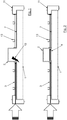
- Fig. 1 shows a sectional view of the underfloor region of a vehicle not according to the invention and represents a problem solved by the invention, namely a collapsing structure 12, in the region of the center tunnel 2 in a side crash of the vehicle.
- the occurring lateral forces on the seat crossmembers 3 can destroy tunnel walls cause the central tunnel 2 and the battery device 1, as the forces meet the relatively weak tunnel walls and can not be sufficiently dissipated there.
- a load path optimization component 4 is installed in the battery device within the battery housing 1, ie inside the battery device, so that the load path optimization component 4 lies within a space available in the center tunnel 2 of the vehicle.
- the load path optimization component 4 is arranged such that lateral forces (indicated by the arrow on the left in FIG Fig. 1 and 2 ) via the load path optimization component 4 of a seat cross member 3 (for example, left of the center tunnel 2 in Fig. 2 ) to the opposite seat cross member 3 (for example, right of the center tunnel 2 in Fig. 2 ) be transmitted.
- the seat cross members are arranged literallyder opposite one another, so almost aligned with each other.
- the load path optimization component 4 By the load path optimization component 4, the walls of the center tunnel 2 are supported on the inside in a side crash case, as formed by the load path optimization component 4, a load path (indicated by the arrow in Lastpfadoptimtechniksbauteil 4), the forces of a seat cross member 3 (indicated by the arrow between seat cross members 3 and floor panels 7) on the opposite seat cross member 3 can derive.
- the load path optimization component 4 is mounted centrally between the two seat cross members 3.
- the load path optimization component 4 lies approximately at the level of the seat cross members 3 and / or the floor panels 7 - preferably, it extends between the two mentioned heights. In the longitudinal direction of the vehicle the load path optimization component 4 is preferably formed at least in the longitudinal region in which the seat cross members 3 are present - see for example Fig. 11 but may also extend well beyond this longitudinal area.
- Seat rails 13 can be mounted on the seat cross member 3.
- the load path optimization component 4 may be an extruded profile, in particular of aluminum, as in FIG Fig. 9 and 10 represented, or a folding part, in particular made of steel, as in Fig. 11 shown.
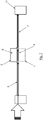
- Fig. 3 shows in a three-dimensional representation of a shell, in particular a platform, a vehicle according to the invention, the position of the section AA, in the Fig. 4 to 7 is shown in more detail in different variants.
- a battery device can have a plurality of battery modules 5 inside the battery housing 1.
- a battery module 5 of the battery device may be fastened within the battery housing 1 on the load path optimization component 4.
- At least one battery module 5 can be arranged above the load path optimization component 4 and within the space available in the center tunnel 2 of the vehicle, in particular be fastened to the load path optimization component 4.
- One or more further battery modules 5 can also be arranged below the load path optimization component 4, preferably below a base plate 7, and for example also on the load path optimization component 4 be attached. These battery modules 5 arranged at the bottom can together form, in particular, a flat accumulator 8.
- the flat accumulator 8 may preferably extend over approximately the entire width of the vehicle. Together with a battery module 5 above the load path optimization component 4 as a further memory area 9, the battery device can thus have approximately an inverted "T" shape.
- the battery device may have an outer circumferential supporting battery frame 14.
- a battery housing 1 formed in this way can have a bulge 15 below the center tunnel 2, ie in the vehicle transverse direction approximately in the middle of the vehicle, in order to provide a free space for an exhaust system 16 and / or other components such as drive components or cabling. Between bulge 15 of the battery case 1 and exhaust system 16 or other components, a shield plate 17 may be provided (see Fig. 6 ).
- the battery device may also have a more compact shape that takes up less space horizontally than a flat storage.
- the battery device below the load path optimization component 4 can have approximately the same width as above the load path optimization component 4 in the space in the center tunnel 2 and thus be formed only in the tunnel area and have approximately rectangular or square shape.
- Fig. 8 again shows a three-dimensional representation of a shell of a vehicle according to the invention and therein the location of the more detailed section BB, which in the Fig. 9 and 10 is shown.
- the load path optimization component 4 is extruded here and has a framework structure that can transmit the load path well.
- the load path optimization component 4 is fastened directly to a battery crossbeam 18 below the load path optimization component 4 via a screw connection 19.
- the battery module 5 is fastened directly above the load path optimization component 4 with the latter by means of a screw 20.
- Fig. 10 is a sectional view around the center tunnel of a vehicle according to the invention, according to BB of Fig. 8 , in a second mounting variant of the battery device (left half of the picture) and in a third mounting variant (right half of the picture) shown.
- the load path optimization component 4 has an extension 6 for a screw connection 21 with the battery cross member 18, in addition or alternatively to the screw connection 19.
- the base plate 7 is also mitverschraubt with this screw 21 in the variant shown on the left, both the bottom plate 7 and the seat cross member. 3
- the load path is for a force striking from the left in Fig. 10 again drawn as a continuous arrow.
- the load path optimization component 4 is thus fastened directly to the seat cross member 3, so that the load path is at least partially not directly via the tunnel walls of the center tunnel 2 on the load path optimization component 4, but at least partially directly from the seat cross members 3 to the load path optimizing component 4.
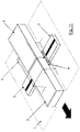
- Fig. 11 is finally a three-dimensional representation of the underbody area of a vehicle according to the invention in an embodiment variant.
- the load path optimization component 4 is formed by a folding part.
- the folding part represents a folding profile which extends from a seat cross member 3 in the direction of the opposite seat cross member 3.
- the load path shown as an arrow through the load path optimization component 4 runs again in the transverse direction, normal to the in Fig. 11 bottom left also shown as arrow direction of travel of the vehicle.
- the same construction of seat cross member 3 - load path optimization component 4 - seat cross member 3, the in Fig. 11 is shown, for example, can be implemented both on front seat cross members 3 and on rear seat cross members 3 in a vehicle.
Landscapes
- Engineering & Computer Science (AREA)
- Chemical & Material Sciences (AREA)
- Combustion & Propulsion (AREA)
- Transportation (AREA)
- Mechanical Engineering (AREA)
- Chemical Kinetics & Catalysis (AREA)
- Electrochemistry (AREA)
- General Chemical & Material Sciences (AREA)
- Body Structure For Vehicles (AREA)
- Arrangement Or Mounting Of Propulsion Units For Vehicles (AREA)
Abstract
Description
- Die vorliegende Erfindung betrifft ein Fahrzeug umfassend einen elektrischen Antriebsmotor und eine Batterievorrichtung als Energiespeicher für den elektrischen Antriebsmotor, also insbesondere ein Elektro- oder Hybridfahrzeug.
- Derartige Fahrzeuge mit einer Batterievorrichtung zur Speisung eines Antriebsmotors benötigen üblicherweise relativ große Batterievorrichtungen, die möglichst platzsparend an dem Fahrzeug untergebracht werden müssen. Dazu ist es bekannt, den Raum nahe an einem Unterboden des Fahrzeuges und insbesondere auch in einem Mitteltunnel des Unterbodens, der oft zur Aufnahme einer Antriebswelle benötigt wird, zu nutzen.
- Die Nutzung eines solchen Raumes in einem Mitteltunnel eines Fahrzeuges hat jedoch den Nachteil, dass bei einem seitlichen Aufprall auf das Fahrzeug ("Seitencrash") die Tunnelwände eine Schwachstelle und somit eine Gefahr für eine dahinterliegende Batterievorrichtung darstellen, da die auftretende Last durch die Beschaffenheit der Tunnelwände und deren geometrischen Aufbau nur sehr wenig abgefangen oder weitergeleitet wird.
- Es ist eine Aufgabe der Erfindung, ein Fahrzeug der genannten Art in dieser Hinsicht zu verbessern und insbesondere ein Fahrzeug anzugeben, das die Sicherheit einer Batterievorrichtung, die im Bereich eines Mitteltunnels des Fahrzeuges angeordnet ist, erhöht.
- Die Lösung der Aufgabe erfolgt durch ein Fahrzeug umfassend einen elektrischen Antriebsmotor und eine Batterievorrichtung als Energiespeicher für den elektrischen Antriebsmotor, wobei die Batterievorrichtung ein Batteriegehäuse aufweist, das zumindest teilweise den in einem Mitteltunnel des Fahrzeugs zur Verfügung stehenden Raum ausfüllt, wobei zu beiden Seiten des Mitteltunnels einander gegenüberliegend angeordnete Sitzquerträger ausgebildet sind, wobei im Batteriegehäuse, innerhalb des im Mitteltunnel des Fahrzeugs zur Verfügung stehenden Raumes, ein Lastpfadoptimierungsbauteil so angeordnet ist, dass Seitenkräfte über das Lastpfadoptimierungsbauteil von einem Sitzquerträger an den gegenüberliegenden Sitzquerträger übertragen werden.
- Erfindungsgemäß wird somit innerhalb der Batterievorrichtung, nämlich im Batteriegehäuse, ein Bauteil, nämlich das sogenannte "Lastpfadoptimierungsbauteil" verbaut, das dazu eingerichtet ist, auftretende Seitenkräfte aus einem Sitzquerträger an einen gegenüberliegenden Sitzquerträger zu übertragen, wobei diese Übertragung der Kräfte vorzugsweise in beinen Richtungen jeweils über die Kette Sitzquerträger - Lastpfadoptimierungsbauteil - Sitzquerträger erfolgt. Das Lastpfadoptimierungsbauteil muss dazu eine ausreichende mechanische Festigkeit aufweisen um auftretende Kräfte in größerem Ausmaß als beispielsweise die Tunnelwände eines Mitteltunnels weiter leiten zu können.
- Dazu sind die Sitzquerträger einander gegenüberliegend, also links und rechts vom Mitteltunnel angeordnet, und stehen daher bevorzugt im Wesentlichen miteinander in Flucht. Um die Lasten von den Sitzquerträgern übertragen zu können, sind bevorzugt zumindest die Enden des Lastpfadoptimierungsbauteils ebenfalls gegenüberliegende den Enden der Sitzquerträger angeordnet, und stehen somit bevorzugt im Wesentlichen ebenfalls in Flucht mit den Sitzquerträgern und/oder überragt der Querschnitt des Lastpfadoptimierungsbauteils die Querschnitte der Sitzquerträger.
- Das Lastpfadoptimierungsbauteil kann somit insbesondere die Wände des Mitteltunnels an deren Innenseite in einem Crashfall abstützen und im Falle eines Seitencrashs einen steifen Lastpfad zusammen mit den Sitzquerträgern ausbilden.
- Die Batterievorrichtung ist durch die Anordnung des Lastpfadoptimierungsbauteils innerhalb der Batterievorrichtung auch einfach, insbesondere von unten, in das Fahrzeug einbaubar.
- Das Lastpfadoptimierungsbauteil ist bevorzugt mittig zwischen zwei Sitzquerträgern montiert, wobei es vorzugsweise eine Verlängerung bzw. eine Projektion der Sitzquerträger darstellt und so den Lastpfad der Sitzquerträger verbindet.
- Insbesondere kann das Lastpfadoptimierungsbauteil - im Gegensatz zum Mitteltunnel - im Wesentlichen eine die beiden Seiten des Mitteltunnels verbindende, gerade verlaufende Form aufweisen, wie zum Beispiel die Form einer Platte.
- Das Lastpfadoptimierungsbauteil kann bevorzugt ein Strangpressprofil, insbesondere aus Aluminium, sein. Das Strangpressprofil kann besonders bevorzugt Verstrebungen aufweisen, insbesondere in Form einer Fachwerkstruktur.
- Das Lastpfadoptimierungsbauteil kann auch ein Faltteil, insbesondere aus Stahl, sein. Insbesondere kann das Faltteil ein im Wesentlichen U-förmiges Profil aufweisen.
- Bevorzugt ist zumindest ein Batteriemodul der Batterievorrichtung im Batteriegehäuse am Lastpfadoptimierungsbauteil befestigt, insbesondere am Lastpfadoptimierungsbauteil verschraubt. Besonders bevorzugt ist zumindest ein Batteriemodul oberhalb des Lastpfadoptimierungsbauteils und innerhalb des im Mitteltunnel des Fahrzeugs zur Verfügung stehenden Raumes, am Lastpfadoptimierungsbauteil befestigt. Bevorzugt ist alternativ oder zusätzlich zumindest ein Batteriemodul unten am Lastpfadoptimierungsbauteil befestigt.
- Das Lastpfadoptimierungsbauteil kann direkt am Sitzquerträger befestigt, insbesondere verschraubt, sein, so dass der Lastpfad zumindest nicht ausschließlich über die Tunnelwände des Mitteltunnels auf das Lastpfadoptimierungsbauteil, sondern zumindest teilweise direkt von den Sitzquerträgern auf das Lastpfadoptimierungsbauteil erfolgt.
- Das Lastpfadoptimierungsbauteil kann auch an einer Bodenplatte befestigt, insbesondere verschraubt sein.
- Das Lastpfadoptimierungsbauteil kann einen Fortsatz aufweisen, wobei das im Batteriegehäuse befindliche Lastpfadoptimierungsbauteil über den Fortsatz an einem Sitzquerträger und/oder einer Bodenplatte befestigt ist, vorzugsweise verschraubt ist.
- Das Lastpfadoptimierungsbauteil kann zumindest im Wesentlichen von einer Wand des Batteriegehäuses bis zur gegenüberliegenden Wand des Batteriegehäuses reichen, wobei diese Wände des Batteriegehäuses bevorzugt Wänden des Mitteltunnels jeweils parallel und unmittelbar benachbart angeordnet sind. Zwischen dem Lastpfadoptimierungsbauteil und den Wänden des Mitteltunnels können auch kleine Freiräume bestehen, die den Einbau der Batterievorrichtung erleichtern.
- Bevorzugt ist die Unterkante des Lastpfadoptimierungsbauteils etwa in Höhe einer Bodenplatte, insbesondere eines Bodenbleches, des Fahrzeuges angeordnet und die Oberkante des Lastpfadoptimierungsbauteils etwa in Höhe der Sitzquerträger angeordnet. Eine "Bodenplatte" kann dabei nicht nur ein planares Bauteil sein, sondern kann auch strukturiert sein, beispielsweise Wölbungen und Kanten aufweisen. Die Bodenplatte kann auch mit dem Mitteltunnel einstückig ausgestaltet sein. Die Bodenplatte kann, aber muss nicht, aus Metall gebildet sein.
- Besonders bevorzugt umfasst die Batterievorrichtung einen Flachspeicher, der unterhalb einer Bodenplatte des Fahrzeuges angeordnet ist und einen weiteren Speicherbereich, der oberhalb der Bodenplatte und oberhalb des Lastpfadoptimierungsbauteils, innerhalb des im Mitteltunnel des Fahrzeugs zur Verfügung stehenden Raumes, angeordnet ist. Der Flachspeicher erstreckt sich bevorzugt über einen großen Teil der Breite oder im Wesentlichen die ganze Breite des Fahrzeuges. Der Flachspeicher kann zusammen mit dem weiteren Speicherbereich im Wesentlichen eine "T"-Form aufweisen.
- Vorzugsweise sind Längsträger und/oder Schweller zu beiden Seiten des Mitteltunnels angeordnet, so dass die Längsträger und/oder Schweller den Lastpfad über die Sitzquerträger und das Lastpfadoptimierungsbauteil unterstützten.
- Das Lastpfadoptimierungsbauteil kann auch Hohlräume aufweisen, die als Kühlmittelkanäle der Batterievorrichtung verwendet werden.
- Die Erfindung wird im Folgenden beispielhaft unter Bezugnahme auf die Zeichnungen beschrieben.
- Fig. 1
- ist eine Schnittansicht des Unterbodenbereichs eines nicht erfindungsgemäßen Fahrzeuges.
- Fig. 2
- ist eine Schnittansicht des Unterbodenbereichs eines erfindungsgemäßen Fahrzeuges, mit Lastpfadoptimierungsbauteil in der Batterievorrichtung.
- Fig. 3
- ist dreidimensionale Darstellung eines Rohbaues und zeigt die Lage des Schnittes A-A.
- Fig. 4
- ist eine detailliertere Schnittansicht des Unterbodenbereichs eines erfindungsgemäßen Fahrzeuges, gemäß A-A der
Fig. 3 . - Fig. 5
- ist eine Schnittansicht des Unterbodenbereichs eines erfindungsgemäßen Fahrzeuges, gemäß A-A der
Fig. 3 , mit einer ersten Formvariante der Batterievorrichtung. - Fig. 6
- ist eine Schnittansicht des Unterbodenbereichs eines erfindungsgemäßen Fahrzeuges, gemäß A-A der
Fig. 3 , mit einer zweiten Formvariante der Batterievorrichtung. - Fig. 7
- ist eine Schnittansicht des Unterbodenbereichs eines erfindungsgemäßen Fahrzeuges, gemäß A-A der
Fig. 3 , mit einer dritten Formvariante der Batterievorrichtung. - Fig. 8
- ist eine dreidimensionale Darstellung eines Rohbaues und zeigt die Lage des Schnittes B-B.
- Fig. 9
- ist eine Schnittansicht um den Mitteltunnel eines erfindungsgemäßen Fahrzeuges, gemäß B-B der
Fig. 8 , in einer ersten Befestigungsvariante der Batterievorrichtung. - Fig. 10
- ist eine Schnittansicht um den Mitteltunnel eines erfindungsgemäßen Fahrzeuges, gemäß B-B der
Fig. 8 , in einer zweiten Befestigungsvariante der Batterievorrichtung (linke Bildhälfte) und in einer dritten Befestigungsvariante (rechte Bildhälfte). - Fig. 11
- ist eine dreidimensionale Darstellung des Unterbodenbereiches eines erfindungsgemäßen Fahrzeuges in einer Ausführungsvariante.
-
Fig. 1 zeigt eine Schnittansicht des Unterbodenbereichs eines nicht erfindungsgemäßen Fahrzeuges und stellt ein durch die Erfindung gelöstes Problem dar, nämlich eine kollabierende Struktur 12, im Bereich des Mitteltunnels 2 bei einem Seitencrash des Fahrzeuges. Die auftretenden Seitenkräfte an den Sitzquerträgern 3 können eine Zerstörung von Tunnelwänden des Mitteltunnels 2 und der Batterievorrichtung 1 bewirken, da die Kräfte auf die relativ schwachen Tunnelwände treffen und dort nicht ausreichend abgeleitet werden können. - Erfindungsgemäß wird, wie in
Fig. 2 dargestellt, ein Lastpfadoptimierungsbauteil 4 in der Batterievorrichtung innerhalb des Batteriegehäuses 1, also innerhalb der Batterievorrichtung verbaut, so dass das Lastpfadoptimierungsbauteil 4 innerhalb eines in dem Mitteltunnel 2 des Fahrzeugs zur Verfügung stehenden Raum liegt. - Das Lastpfadoptimierungsbauteil 4 ist so angeordnet, dass Seitenkräfte (angedeutet durch den Pfeil links in
Fig. 1 und 2 ) über das Lastpfadoptimierungsbauteil 4 von einem Sitzquerträger 3 (zum Beispiel links des Mitteltunnels 2 inFig. 2 ) an den gegenüberliegenden Sitzquerträger 3 (zum Beispiel rechts des Mitteltunnels 2 inFig. 2 ) übertragen werden. Die Sitzquerträger sind einender gegenüberliegend angeordnet, also annähernd miteinander in Flucht stehend. Durch das Lastpfadoptimierungsbauteil 4 werden die Wände des Mitteltunnels 2 an deren Innenseite in einem Seiten-Crashfall abgestützt, da durch das Lastpfadoptimierungsbauteil 4 ein Lastpfad ausgebildet wird (angedeutet durch den Pfeil im Lastpfadoptimierungsbauteil 4), der die Kräfte eines Sitzquerträgers 3 (angedeutet durch den Pfeil zwischen Sitzquerträgern 3 und Bodenplatten 7) auf den gegenüberliegenden Sitzquerträger 3 ableiten kann. - Das Lastpfadoptimierungsbauteil 4 ist mittig zwischen den zwei Sitzquerträgern 3 montiert.
- Das Lastpfadoptimierungsbauteil 4 liegt dabei etwa in Höhe der Sitzquerträger 3 und/oder der Bodenplatten 7 - bevorzugt erstreckt es sich zwischen den beiden genannten Höhen. In Längsrichtung des Fahrzeuges ist das Lastpfadoptimierungsbauteil 4 bevorzugt zumindest in dem Längsbereich ausgebildet, in dem die Sitzquerträger 3 vorliegen - siehe zum Beispiel
Fig. 11 , kann sich aber auch deutlich über diesen Längsbereich hinaus erstrecken. - Am Sitzquerträger 3 können Sitzschienen 13 montiert sein.
- Das Lastpfadoptimierungsbauteil 4 kann ein Strangpressprofil, insbesondere aus Aluminium, sein, wie in
Fig. 9 und10 dargestellt, oder ein Faltteil, insbesondere aus Stahl, wie inFig. 11 dargestellt. -
Fig. 3 zeigt in einer dreidimensionalen Darstellung eines Rohbaues, insbesondere einer Plattform, eines erfindungsgemäßen Fahrzeuges die Lage des Schnittes A-A, der in denFig. 4 bis 7 in verschiedenen Varianten näher dargestellt ist. - Wie in
Fig. 4 ersichtlich, kann eine Batterievorrichtung mehrere Batteriemodule 5 innerhalb des Batteriegehäuses 1 aufweisen. - Ein Batteriemodul 5 der Batterievorrichtung kann innerhalb des Batteriegehäuses 1 am Lastpfadoptimierungsbauteil 4 befestigt sein.
- Es kann zumindest ein Batteriemodul 5 oberhalb des Lastpfadoptimierungsbauteils 4 und innerhalb des im Mitteltunnel 2 des Fahrzeugs zur Verfügung stehenden Raumes, angeordnet sein, insbesondere am Lastpfadoptimierungsbauteil 4 befestigt sein.
- Ein oder mehrere weitere Batteriemodule 5 können auch unterhalb des Lastpfadoptimierungsbauteils 4, bevorzugt unterhalb einer Bodenplatte 7, angeordnet sein und beispielsweise ebenfalls am Lastpfadoptimierungsbauteil 4 befestigt sein. Diese unten angeordneten Batteriemodule 5 können zusammen insbesondere einen Flachspeicher 8 bilden. Der Flachspeicher 8 kann sich bevorzugt über annähernd die gesamte Breite des Fahrzeuges erstrecken. Zusammen mit einem Batteriemodul 5 oberhalb des Lastpfadoptimierungsbauteils 4 als weiterem Speicherbereich 9 kann die Batterievorrichtung somit annähernd eine auf den Kopf gestellte "T"-Form aufweisen.
- Die Batterievorrichtung kann einen außen umlaufenden tragenden Batterierahmen 14 aufweisen.
- Die oben angegebene Ausbildung der Batterievorrichtung und des Batteriegehäuses 1, umfassend einen Flachspeicher 8 und einen weiteren Speicherbereich 9 im Mitteltunnel 2, der insgesamt eine umgekehrte "T"-Form bildet, ist in der
Fig. 5 besonders gut ersichtlich. - Ein derart geformtes Batteriegehäuse 1 kann unterhalb des Mitteltunnels 2, also in Fahrzeugquerrichtung etwa in der Mitte des Fahrzeuges, eine Ausbuchtung 15 aufweisen, um einen freien Raum für eine Abgasanlage 16 und/oder andere Komponenten, wie etwa Antriebskomponenten oder Verkabelungen bereit zu stellen. Zwischen Ausbuchtung 15 des Batteriegehäuses 1 und Abgasanlage 16 oder anderen Komponenten kann ein Abschirmblech 17 vorgesehen sein (siehe
Fig. 6 ). - Wie in
Fig. 7 dargestellt, kann die Batterievorrichtung auch eine kompaktere Form aufweisen, die horizontal weniger Platz beansprucht als ein Flachspeicher. Insbesondere kann die Batterievorrichtung unterhalb des Lastpfadoptimierungsbauteils 4 etwa die selbe Breite aufweisen, wie oberhalb des Lastpfadoptimierungsbauteils 4 im Raum im Mitteltunnel 2 und somit nur im Tunnelbereich ausgebildet sein und etwa rechteckige oder quadratische Form aufweisen. -
Fig. 8 zeigt wieder eine dreidimensionale Darstellung eines Rohbaus eines erfindungsgemäßen Fahrzeuges und darin die Lage des detaillierteren Schnittes B-B, der in denFig. 9 und10 dargestellt ist. - Das Lastpfadoptimierungsbauteil 4 ist hier stranggepresst und weist eine Fachwerkstruktur auf, die den Lastpfad gut übertragen kann.
Das Lastpfadoptimierungsbauteil 4 ist über eine Verschraubung 19 an einem Batteriequertäger 18 unterhalb des Lastpfadoptimierungsbauteils 4 direkt befestigt. - Ferner ist das Batteriemodul 5 oberhalb des Lastpfadoptimierungsbauteils 4 mit diesem mittels einer Verschraubung 20 direkt befestigt.
- In
Fig. 10 ist eine Schnittansicht um den Mitteltunnel eines erfindungsgemäßen Fahrzeuges, gemäß B-B derFig. 8 , in einer zweiten Befestigungsvariante der Batterievorrichtung (linke Bildhälfte) und in einer dritten Befestigungsvariante (rechte Bildhälfte) dargestellt. - Das Lastpfadoptimierungsbauteil 4 weist in beiden Varianten einen Fortsatz 6 für eine Verschraubung 21 mit dem Batteriequerträger 18, zusätzlich oder alternativ zur Verschraubung 19, auf. In der der rechts dargestellten Variante ist mit dieser Verschraubung 21 zusätzlich die Bodenplatte 7 mitverschraubt, in der links dargestellten Variante sowohl die Bodenplatte 7 als auch der Sitzquerträger 3.
- Der Lastpfad ist für eine von links auftreffende Kraft in
Fig. 10 wieder als durchgehender Pfeil eingezeichnet. - Das Lastpfadoptimierungsbauteil 4 ist somit direkt am Sitzquerträger 3 befestigt, so dass der Lastpfad zumindest nicht ausschließlich über die Tunnelwände des Mitteltunnels 2 auf das Lastpfadoptimierungsbauteil 4, sondern zumindest teilweise direkt von den Sitzquerträgern 3 auf das Lastpfadoptimierungsbauteil 4 erfolgt.
-
Fig. 11 ist schließlich eine dreidimensionale Darstellung des Unterbodenbereiches eines erfindungsgemäßen Fahrzeuges in einer Ausführungsvariante. In dieser Variante ist das Lastpfadoptimierungsbauteil 4 durch ein Faltteil gebildet. Das Faltteil stellt ein Faltprofil dar, das sich von einem Sitzquerträger 3 in Richtung zum gegenüberliegenden Sitzquerträger 3 erstreckt. Der als Pfeil eingezeichnete Lastpfad durch das Lastpfadoptimierungsbauteil 4 verläuft wieder in Querrichtung, normal auf die inFig. 11 unten links ebenfalls als Pfeil dargestellte Fahrtrichtung des Fahrzeuges. Der selbe Aufbau von Sitzquerträger 3 - Lastpfadoptimierungsbauteil 4 - Sitzquerträger 3, der inFig, 11 dargestellt ist, kann beispielsweise sowohl an vorderen Sitzquerträgern 3 als auch an hinteren Sitzquerträgern 3 in einem Fahrzeug realisiert sein. -
- 1
- Batteriegehäuse
- 2
- Mitteltunnel
- 3
- Sitzquerträger
- 4
- Lastpfadoptimierungsbauteil
- 5
- Batteriemodul
- 6
- Fortsatz
- 7
- Bodenplatte
- 8
- Flachspeicher
- 9
- weiterer Speicherbereich
- 10
- Längsträger
- 11
- Schweller
- 12
- kollabierende Struktur
- 13
- Sitzschiene
- 14
- Batterierahmen
- 15
- Ausbuchtung
- 16
- Abgasanlage
- 17
- Abschirmblech
- 18
- Batteriequertäger
- 19
- Verschraubung Batteriequertäger
- 20
- Verschraubung Batteriemodul
- 21
- Verschraubung Lastpfadoptimierungsbauteil
Claims (10)
- Fahrzeug umfassend einen elektrischen Antriebsmotor und eine Batterievorrichtung als Energiespeicher für den elektrischen Antriebsmotor, wobei die Batterievorrichtung ein Batteriegehäuse (1) aufweist, das zumindest teilweise den in einem Mitteltunnel (2) des Fahrzeugs zur Verfügung stehenden Raum ausfüllt, wobei an beiden Seiten des Mitteltunnels (2) einander gegenüberliegend angeordnete Sitzquerträger (3) ausgebildet sind,
dadurch gekennzeichnet, dass im Batteriegehäuse (1), innerhalb des im Mitteltunnel (2) des Fahrzeugs zur Verfügung stehenden Raumes, ein Lastpfadoptimierungsbauteil (4) so angeordnet ist, dass Seitenkräfte über das Lastpfadoptimierungsbauteil (4) von einem Sitzquerträger (3) an den gegenüberliegenden Sitzquerträger (3) übertragen werden. - Fahrzeug nach zumindest einem der vorhergehenden Ansprüche,
dadurch gekennzeichnet, dass das Lastpfadoptimierungsbauteil (4) ein Strangpressprofil, insbesondere aus Aluminium, ist, oder ein Faltteil, insbesondere aus Stahl. - Fahrzeug nach zumindest einem der vorhergehenden Ansprüche,
dadurch gekennzeichnet, dass zumindest ein Batteriemodul (5) der Batterievorrichtung innerhalb des Batteriegehäuses (1) am Lastpfadoptimierungsbauteil (4) befestigt ist, insbesondere zumindest ein Batteriemodul (5) oberhalb des Lastpfadoptimierungsbauteils (4) und innerhalb des im Mitteltunnel (2) des Fahrzeugs zur Verfügung stehenden Raumes, am Lastpfadoptimierungsbauteil (4) befestigt ist. - Fahrzeug nach zumindest einem der vorhergehenden Ansprüche,
dadurch gekennzeichnet, dass das Lastpfadoptimierungsbauteil (4) direkt am Sitzquerträger (3) befestigt ist, so dass der Lastpfad zumindest nicht ausschließlich über die Tunnelwände des Mitteltunnels (2) auf das Lastpfadoptimierungsbauteil (4), sondern zumindest teilweise direkt von den Sitzquerträgern (3) auf das Lastpfadoptimierungsbauteil (4) erfolgt. - Fahrzeug nach Anspruch 4,
dadurch gekennzeichnet, dass das Lastpfadoptimierungsbauteil (4) einen Fortsatz (6) aufweist, wobei das im Batteriegehäuse (1) befindliche Lastpfadoptimierungsbauteil (4) über den Fortsatz (6) an einem Sitzquerträger (3) und/oder einer Bodenplatte (7) befestigt, vorzugsweise verschraubt, ist. - Fahrzeug nach zumindest einem der vorhergehenden Ansprüche,
dadurch gekennzeichnet, dass das Lastpfadoptimierungsbauteil (4) zumindest im Wesentlichen von einer Wand des Batteriegehäuses (1) bis zur gegenüberliegenden Wand des Batteriegehäuses (1) reicht, wobei diese Wände des Batteriegehäuses (1) bevorzugt Wänden des Mitteltunnels (2) jeweils parallel und unmittelbar benachbart angeordnet sind. - Fahrzeug nach zumindest einem der vorhergehenden Ansprüche,
dadurch gekennzeichnet, dass die Unterkante des Lastpfadoptimierungsbauteils (4) etwa in Höhe einer Bodenplatte (7) des Fahrzeuges angeordnet ist und die Oberkante des Lastpfadoptimierungsbauteils (4) etwa in Höhe der Sitzquerträger (3) angeordnet ist. - Fahrzeug nach zumindest einem der vorhergehenden Ansprüche,
dadurch gekennzeichnet, dass die Batterievorrichtung (1) einen Flachspeicher (8) umfasst, der unterhalb einer Bodenplatte (7) des Fahrzeuges angeordnet ist und einen weiteren Speicherbereich (9), der oberhalb der Bodenplatte (7) und oberhalb des Lastpfadoptimierungsbauteils (4), innerhalb des im Mitteltunnel (2) des Fahrzeugs zur Verfügung stehenden Raumes, angeordnet ist. - Fahrzeug nach zumindest einem der vorhergehenden Ansprüche,
dadurch gekennzeichnet, dass Längsträger (10) und/ oder Schweller (11) zu beiden Seiten des Mitteltunnels (2) angeordnet sind, so dass die Längsträger (10) und/oder Schweller (11) den Lastpfad über die Sitzquerträger (3) und das Lastpfadoptimierungsbauteil (4) unterstützten. - Fahrzeug nach zumindest einem der vorhergehenden Ansprüche,
dadurch gekennzeichnet, dass das Lastpfadoptimierungsbauteil (4) Hohlräume aufweist, die als Kühlmittelkanäle der Batterievorrichtung (1) verwendet werden.
Priority Applications (2)
| Application Number | Priority Date | Filing Date | Title |
|---|---|---|---|
| US15/875,145 US10737729B2 (en) | 2017-02-14 | 2018-01-19 | Vehicle |
| CN201810127744.8A CN108422844A (zh) | 2017-02-14 | 2018-02-08 | 车辆 |
Applications Claiming Priority (1)
| Application Number | Priority Date | Filing Date | Title |
|---|---|---|---|
| EP17156001 | 2017-02-14 |
Publications (2)
| Publication Number | Publication Date |
|---|---|
| EP3360759A1 true EP3360759A1 (de) | 2018-08-15 |
| EP3360759B1 EP3360759B1 (de) | 2019-04-03 |
Family
ID=58162428
Family Applications (1)
| Application Number | Title | Priority Date | Filing Date |
|---|---|---|---|
| EP17171027.0A Active EP3360759B1 (de) | 2017-02-14 | 2017-05-15 | Fahrzeug mit einem elektrischen antriebsmotor |
Country Status (3)
| Country | Link |
|---|---|
| US (1) | US10737729B2 (de) |
| EP (1) | EP3360759B1 (de) |
| CN (1) | CN108422844A (de) |
Cited By (3)
| Publication number | Priority date | Publication date | Assignee | Title |
|---|---|---|---|---|
| DE102019128940A1 (de) * | 2019-10-27 | 2021-04-29 | Ford Global Technologies Llc | Batteriewanne zum Schutz der Fahrzeugbatterie für ein Hybridkraftfahrzeug |
| DE102021108711B3 (de) | 2021-04-08 | 2022-03-24 | Bayerische Motoren Werke Aktiengesellschaft | Bauteilverbund für einen Rohbau eines Kraftwagens, Verfahren zu dessen Herstellung sowie Baukastensystem für einen solchen Bauteilverbund |
| WO2023072807A1 (de) * | 2021-10-29 | 2023-05-04 | Mercedes-Benz Group AG | Fahrzeug mit einer elektrischen energiespeichereinheit |
Families Citing this family (8)
| Publication number | Priority date | Publication date | Assignee | Title |
|---|---|---|---|---|
| JP6683779B2 (ja) * | 2018-08-31 | 2020-04-22 | 本田技研工業株式会社 | バッテリパックの冷却構造 |
| DE102018132255A1 (de) | 2018-12-14 | 2020-06-18 | Bayerische Motoren Werke Aktiengesellschaft | Energiespeicher-Bodengruppe für einen Kraftwagenrohbau |
| DE102019122195A1 (de) * | 2019-08-19 | 2021-02-25 | Bayerische Motoren Werke Aktiengesellschaft | Gruppe von Kraftfahrzeugen |
| CN114348118B (zh) * | 2020-10-12 | 2024-04-09 | 鸿华先进科技股份有限公司 | 模块化车身及模块化车身制造方法 |
| JP7369681B2 (ja) * | 2020-11-11 | 2023-10-26 | 本田技研工業株式会社 | 電池パック搭載車両 |
| SE2150957A1 (en) * | 2021-07-16 | 2023-01-17 | Nat Electric Vehicle Sweden Ab | Structural Rechargeable Electric Energy Storage System |
| JP2023046924A (ja) * | 2021-09-24 | 2023-04-05 | 本田技研工業株式会社 | 車体下部構造 |
| CN115871429A (zh) * | 2021-09-30 | 2023-03-31 | 马自达汽车株式会社 | 车体构造 |
Citations (3)
| Publication number | Priority date | Publication date | Assignee | Title |
|---|---|---|---|---|
| US20090134668A1 (en) * | 2007-11-24 | 2009-05-28 | Dr. Ing. H.C. F. Porsche Aktiengesellschaft | Bodywork |
| DE102010045997A1 (de) * | 2010-05-10 | 2011-11-10 | Volkswagen Ag | Kraftfahrzeug mit einer crashsicheren Batterie-Box im Mitteltunnel |
| DE102013016824A1 (de) * | 2013-10-10 | 2015-04-16 | Daimler Ag | Fahrzeug mit zumindest einer Batterie |
Family Cites Families (18)
| Publication number | Priority date | Publication date | Assignee | Title |
|---|---|---|---|---|
| JP5173182B2 (ja) * | 2006-11-13 | 2013-03-27 | トヨタ自動車株式会社 | 蓄電装置ユニット |
| JP4858203B2 (ja) * | 2007-02-07 | 2012-01-18 | トヨタ自動車株式会社 | 自動車 |
| US8960776B2 (en) * | 2007-04-20 | 2015-02-24 | Honda Motor Co., Ltd. | Vehicle bed frame assembly, system and method |
| DE112009004862B4 (de) * | 2009-05-28 | 2015-11-19 | Toyota Jidosha Kabushiki Kaisha | Brennstoffzellenanordnung und Fahrzeug |
| FR2957888B1 (fr) * | 2010-03-29 | 2012-03-23 | Renault Sa | Vehicule et support de reservoir d'energie associe |
| JP5364767B2 (ja) * | 2011-09-26 | 2013-12-11 | 富士重工業株式会社 | 車両用バッテリ支持構造 |
| JP5483293B2 (ja) * | 2011-11-29 | 2014-05-07 | 富士重工業株式会社 | ハイブリッド自動車の車体構造 |
| US9236592B2 (en) * | 2012-11-27 | 2016-01-12 | Ford Global Technologies, Llc | Protective vehicle battery cage and method of making a battery cage |
| CN104340282B (zh) * | 2014-10-23 | 2017-09-12 | 奇瑞汽车股份有限公司 | 一种汽车电池保护结构 |
| JP6364500B2 (ja) * | 2014-11-07 | 2018-07-25 | 本田技研工業株式会社 | 車両 |
| DE102015213860B4 (de) * | 2015-07-22 | 2019-06-06 | Volkswagen Aktiengesellschaft | Batterieanordnung in einem elektrisch betriebenen Fahrzeug |
| US9499205B1 (en) * | 2015-09-23 | 2016-11-22 | Ford Global Technologies, Llc | Hybrid vehicle packaging system |
| JP6512162B2 (ja) * | 2016-04-21 | 2019-05-15 | トヨタ自動車株式会社 | 車両のバッテリ搭載構造 |
| EP3261149B1 (de) * | 2016-06-20 | 2021-09-15 | Magna Steyr Fahrzeugtechnik AG & Co KG | Befestigungsanordnung |
| JP6555236B2 (ja) * | 2016-11-30 | 2019-08-07 | トヨタ自動車株式会社 | 車体下部構造 |
| JP6475270B2 (ja) * | 2017-01-20 | 2019-02-27 | 株式会社Subaru | 自動車車両 |
| US10252751B2 (en) * | 2017-03-07 | 2019-04-09 | Ford Global Technologies, Llc | Inflatable tunnel reinforcement |
| JP6541724B2 (ja) * | 2017-07-10 | 2019-07-10 | 株式会社Subaru | 自動車車両 |
-
2017
- 2017-05-15 EP EP17171027.0A patent/EP3360759B1/de active Active
-
2018
- 2018-01-19 US US15/875,145 patent/US10737729B2/en active Active
- 2018-02-08 CN CN201810127744.8A patent/CN108422844A/zh active Pending
Patent Citations (3)
| Publication number | Priority date | Publication date | Assignee | Title |
|---|---|---|---|---|
| US20090134668A1 (en) * | 2007-11-24 | 2009-05-28 | Dr. Ing. H.C. F. Porsche Aktiengesellschaft | Bodywork |
| DE102010045997A1 (de) * | 2010-05-10 | 2011-11-10 | Volkswagen Ag | Kraftfahrzeug mit einer crashsicheren Batterie-Box im Mitteltunnel |
| DE102013016824A1 (de) * | 2013-10-10 | 2015-04-16 | Daimler Ag | Fahrzeug mit zumindest einer Batterie |
Cited By (5)
| Publication number | Priority date | Publication date | Assignee | Title |
|---|---|---|---|---|
| DE102019128940A1 (de) * | 2019-10-27 | 2021-04-29 | Ford Global Technologies Llc | Batteriewanne zum Schutz der Fahrzeugbatterie für ein Hybridkraftfahrzeug |
| US11731498B2 (en) | 2019-10-27 | 2023-08-22 | Ford Global Technologies, Llc | Battery tray for protecting the vehicle battery of a hybrid motor |
| DE102019128940B4 (de) * | 2019-10-27 | 2025-07-31 | Ford Global Technologies Llc | Batteriewanne zum Schutz der Fahrzeugbatterie für ein Hybridkraftfahrzeug |
| DE102021108711B3 (de) | 2021-04-08 | 2022-03-24 | Bayerische Motoren Werke Aktiengesellschaft | Bauteilverbund für einen Rohbau eines Kraftwagens, Verfahren zu dessen Herstellung sowie Baukastensystem für einen solchen Bauteilverbund |
| WO2023072807A1 (de) * | 2021-10-29 | 2023-05-04 | Mercedes-Benz Group AG | Fahrzeug mit einer elektrischen energiespeichereinheit |
Also Published As
| Publication number | Publication date |
|---|---|
| CN108422844A (zh) | 2018-08-21 |
| EP3360759B1 (de) | 2019-04-03 |
| US10737729B2 (en) | 2020-08-11 |
| US20180229772A1 (en) | 2018-08-16 |
Similar Documents
| Publication | Publication Date | Title |
|---|---|---|
| EP3360759B1 (de) | Fahrzeug mit einem elektrischen antriebsmotor | |
| DE102018113460B4 (de) | Karosseriestruktur für ein Elektrofahrzeug | |
| DE102007023391B4 (de) | Schutzgehäuse für eine Fahrzeugbatterie und Kraftfahrzeug mit einem derartigen Schutzgehäuse | |
| DE102016203209B4 (de) | Zumindest teilweise elektrisch betreibbares Kraftfahrzeug | |
| DE102018115211A1 (de) | Untere Abschnittsstruktur einer Fahrzeugkarosserie | |
| DE3332919C2 (de) | ||
| WO2023083606A1 (de) | Karosserierohbau mit einer antriebsbatterie | |
| DE2426050A1 (de) | Selbsttragende fahrzeugkarosserie | |
| DE102013223636A1 (de) | Schutzkäfig für eine fahrzeugbatterie und verfahren zur herstellung eines batteriekäfigs | |
| WO2018007204A1 (de) | Kraftfahrzeug | |
| DE102018215954A1 (de) | Kraftfahrzeug und Batterie | |
| EP2508407B1 (de) | Gerüst, insbesondere für elektrische Einrichtungen in einem Schienenfahrzeug, und Verfahren zur Herstellung des Gerüsts | |
| DE102011001861B4 (de) | Tragstruktur für ein Kraftfahrzeug und Kraftfahrzeug | |
| DE102018120296A1 (de) | Batteriegehäuse | |
| DE102016203210A1 (de) | Zumindest teilweise elektrisch betreibbares Kraftfahrzeug | |
| EP2819208B1 (de) | Batteriesystem | |
| DE102022104569B4 (de) | Traktionsbatterie-Fahrzeugboden | |
| DE10332634B4 (de) | Fahrzeug-Tragstruktur | |
| DE102018210575B4 (de) | Vorrichtung zur Reduzierung einer Krafteinwirkung auf eine Batterie, sowie Kraftfahrzeug mit einer solchen Vorrichtung | |
| EP4163193B1 (de) | Vorbaustruktur für ein kraftfahrzeug mit einer hinter einem kühlmodul angeordneten crash-struktur | |
| WO2018210423A1 (de) | Selbsttragende baugruppe für ein fahrzeug | |
| DE60010329T2 (de) | Verstärktes kraftfahrzeuginnenraum | |
| EP4342703A1 (de) | Nutzfahrzeug | |
| DE102019102901A1 (de) | Kraftfahrzeug-Bodenanordnung mit einer Traktionsbatterie | |
| DE19522341C2 (de) | Fahrzeugrahmen für ein Transportfahrzeug |
Legal Events
| Date | Code | Title | Description |
|---|---|---|---|
| PUAI | Public reference made under article 153(3) epc to a published international application that has entered the european phase |
Free format text: ORIGINAL CODE: 0009012 |
|
| STAA | Information on the status of an ep patent application or granted ep patent |
Free format text: STATUS: REQUEST FOR EXAMINATION WAS MADE |
|
| 17P | Request for examination filed |
Effective date: 20180117 |
|
| AK | Designated contracting states |
Kind code of ref document: A1 Designated state(s): AL AT BE BG CH CY CZ DE DK EE ES FI FR GB GR HR HU IE IS IT LI LT LU LV MC MK MT NL NO PL PT RO RS SE SI SK SM TR |
|
| AX | Request for extension of the european patent |
Extension state: BA ME |
|
| RIC1 | Information provided on ipc code assigned before grant |
Ipc: B62D 25/20 20060101ALI20181024BHEP Ipc: B60K 1/04 20060101ALI20181024BHEP Ipc: B62D 21/15 20060101AFI20181024BHEP |
|
| GRAP | Despatch of communication of intention to grant a patent |
Free format text: ORIGINAL CODE: EPIDOSNIGR1 |
|
| STAA | Information on the status of an ep patent application or granted ep patent |
Free format text: STATUS: GRANT OF PATENT IS INTENDED |
|
| INTG | Intention to grant announced |
Effective date: 20181211 |
|
| GRAS | Grant fee paid |
Free format text: ORIGINAL CODE: EPIDOSNIGR3 |
|
| GRAA | (expected) grant |
Free format text: ORIGINAL CODE: 0009210 |
|
| STAA | Information on the status of an ep patent application or granted ep patent |
Free format text: STATUS: THE PATENT HAS BEEN GRANTED |
|
| AK | Designated contracting states |
Kind code of ref document: B1 Designated state(s): AL AT BE BG CH CY CZ DE DK EE ES FI FR GB GR HR HU IE IS IT LI LT LU LV MC MK MT NL NO PL PT RO RS SE SI SK SM TR |
|
| REG | Reference to a national code |
Ref country code: GB Ref legal event code: FG4D Free format text: NOT ENGLISH |
|
| REG | Reference to a national code |
Ref country code: CH Ref legal event code: EP Ref country code: AT Ref legal event code: REF Ref document number: 1115389 Country of ref document: AT Kind code of ref document: T Effective date: 20190415 |
|
| REG | Reference to a national code |
Ref country code: DE Ref legal event code: R096 Ref document number: 502017001028 Country of ref document: DE |
|
| REG | Reference to a national code |
Ref country code: IE Ref legal event code: FG4D Free format text: LANGUAGE OF EP DOCUMENT: GERMAN |
|
| REG | Reference to a national code |
Ref country code: NL Ref legal event code: MP Effective date: 20190403 |
|
| REG | Reference to a national code |
Ref country code: LT Ref legal event code: MG4D |
|
| PG25 | Lapsed in a contracting state [announced via postgrant information from national office to epo] |
Ref country code: NL Free format text: LAPSE BECAUSE OF FAILURE TO SUBMIT A TRANSLATION OF THE DESCRIPTION OR TO PAY THE FEE WITHIN THE PRESCRIBED TIME-LIMIT Effective date: 20190403 |
|
| PG25 | Lapsed in a contracting state [announced via postgrant information from national office to epo] |
Ref country code: NO Free format text: LAPSE BECAUSE OF FAILURE TO SUBMIT A TRANSLATION OF THE DESCRIPTION OR TO PAY THE FEE WITHIN THE PRESCRIBED TIME-LIMIT Effective date: 20190703 Ref country code: HR Free format text: LAPSE BECAUSE OF FAILURE TO SUBMIT A TRANSLATION OF THE DESCRIPTION OR TO PAY THE FEE WITHIN THE PRESCRIBED TIME-LIMIT Effective date: 20190403 Ref country code: SE Free format text: LAPSE BECAUSE OF FAILURE TO SUBMIT A TRANSLATION OF THE DESCRIPTION OR TO PAY THE FEE WITHIN THE PRESCRIBED TIME-LIMIT Effective date: 20190403 Ref country code: FI Free format text: LAPSE BECAUSE OF FAILURE TO SUBMIT A TRANSLATION OF THE DESCRIPTION OR TO PAY THE FEE WITHIN THE PRESCRIBED TIME-LIMIT Effective date: 20190403 Ref country code: PT Free format text: LAPSE BECAUSE OF FAILURE TO SUBMIT A TRANSLATION OF THE DESCRIPTION OR TO PAY THE FEE WITHIN THE PRESCRIBED TIME-LIMIT Effective date: 20190803 Ref country code: AL Free format text: LAPSE BECAUSE OF FAILURE TO SUBMIT A TRANSLATION OF THE DESCRIPTION OR TO PAY THE FEE WITHIN THE PRESCRIBED TIME-LIMIT Effective date: 20190403 Ref country code: ES Free format text: LAPSE BECAUSE OF FAILURE TO SUBMIT A TRANSLATION OF THE DESCRIPTION OR TO PAY THE FEE WITHIN THE PRESCRIBED TIME-LIMIT Effective date: 20190403 Ref country code: LT Free format text: LAPSE BECAUSE OF FAILURE TO SUBMIT A TRANSLATION OF THE DESCRIPTION OR TO PAY THE FEE WITHIN THE PRESCRIBED TIME-LIMIT Effective date: 20190403 Ref country code: CZ Free format text: LAPSE BECAUSE OF FAILURE TO SUBMIT A TRANSLATION OF THE DESCRIPTION OR TO PAY THE FEE WITHIN THE PRESCRIBED TIME-LIMIT Effective date: 20190403 |
|
| PG25 | Lapsed in a contracting state [announced via postgrant information from national office to epo] |
Ref country code: BG Free format text: LAPSE BECAUSE OF FAILURE TO SUBMIT A TRANSLATION OF THE DESCRIPTION OR TO PAY THE FEE WITHIN THE PRESCRIBED TIME-LIMIT Effective date: 20190703 Ref country code: LV Free format text: LAPSE BECAUSE OF FAILURE TO SUBMIT A TRANSLATION OF THE DESCRIPTION OR TO PAY THE FEE WITHIN THE PRESCRIBED TIME-LIMIT Effective date: 20190403 Ref country code: RS Free format text: LAPSE BECAUSE OF FAILURE TO SUBMIT A TRANSLATION OF THE DESCRIPTION OR TO PAY THE FEE WITHIN THE PRESCRIBED TIME-LIMIT Effective date: 20190403 Ref country code: GR Free format text: LAPSE BECAUSE OF FAILURE TO SUBMIT A TRANSLATION OF THE DESCRIPTION OR TO PAY THE FEE WITHIN THE PRESCRIBED TIME-LIMIT Effective date: 20190704 Ref country code: PL Free format text: LAPSE BECAUSE OF FAILURE TO SUBMIT A TRANSLATION OF THE DESCRIPTION OR TO PAY THE FEE WITHIN THE PRESCRIBED TIME-LIMIT Effective date: 20190403 |
|
| PG25 | Lapsed in a contracting state [announced via postgrant information from national office to epo] |
Ref country code: IS Free format text: LAPSE BECAUSE OF FAILURE TO SUBMIT A TRANSLATION OF THE DESCRIPTION OR TO PAY THE FEE WITHIN THE PRESCRIBED TIME-LIMIT Effective date: 20190803 |
|
| REG | Reference to a national code |
Ref country code: DE Ref legal event code: R097 Ref document number: 502017001028 Country of ref document: DE |
|
| PG25 | Lapsed in a contracting state [announced via postgrant information from national office to epo] |
Ref country code: RO Free format text: LAPSE BECAUSE OF FAILURE TO SUBMIT A TRANSLATION OF THE DESCRIPTION OR TO PAY THE FEE WITHIN THE PRESCRIBED TIME-LIMIT Effective date: 20190403 Ref country code: SK Free format text: LAPSE BECAUSE OF FAILURE TO SUBMIT A TRANSLATION OF THE DESCRIPTION OR TO PAY THE FEE WITHIN THE PRESCRIBED TIME-LIMIT Effective date: 20190403 Ref country code: EE Free format text: LAPSE BECAUSE OF FAILURE TO SUBMIT A TRANSLATION OF THE DESCRIPTION OR TO PAY THE FEE WITHIN THE PRESCRIBED TIME-LIMIT Effective date: 20190403 Ref country code: DK Free format text: LAPSE BECAUSE OF FAILURE TO SUBMIT A TRANSLATION OF THE DESCRIPTION OR TO PAY THE FEE WITHIN THE PRESCRIBED TIME-LIMIT Effective date: 20190403 Ref country code: MC Free format text: LAPSE BECAUSE OF FAILURE TO SUBMIT A TRANSLATION OF THE DESCRIPTION OR TO PAY THE FEE WITHIN THE PRESCRIBED TIME-LIMIT Effective date: 20190403 |
|
| REG | Reference to a national code |
Ref country code: BE Ref legal event code: MM Effective date: 20190531 |
|
| PLBE | No opposition filed within time limit |
Free format text: ORIGINAL CODE: 0009261 |
|
| STAA | Information on the status of an ep patent application or granted ep patent |
Free format text: STATUS: NO OPPOSITION FILED WITHIN TIME LIMIT |
|
| PG25 | Lapsed in a contracting state [announced via postgrant information from national office to epo] |
Ref country code: SM Free format text: LAPSE BECAUSE OF FAILURE TO SUBMIT A TRANSLATION OF THE DESCRIPTION OR TO PAY THE FEE WITHIN THE PRESCRIBED TIME-LIMIT Effective date: 20190403 Ref country code: IT Free format text: LAPSE BECAUSE OF FAILURE TO SUBMIT A TRANSLATION OF THE DESCRIPTION OR TO PAY THE FEE WITHIN THE PRESCRIBED TIME-LIMIT Effective date: 20190403 Ref country code: LU Free format text: LAPSE BECAUSE OF NON-PAYMENT OF DUE FEES Effective date: 20190515 |
|
| 26N | No opposition filed |
Effective date: 20200106 |
|
| PG25 | Lapsed in a contracting state [announced via postgrant information from national office to epo] |
Ref country code: TR Free format text: LAPSE BECAUSE OF FAILURE TO SUBMIT A TRANSLATION OF THE DESCRIPTION OR TO PAY THE FEE WITHIN THE PRESCRIBED TIME-LIMIT Effective date: 20190403 |
|
| PG25 | Lapsed in a contracting state [announced via postgrant information from national office to epo] |
Ref country code: IE Free format text: LAPSE BECAUSE OF NON-PAYMENT OF DUE FEES Effective date: 20190515 |
|
| PG25 | Lapsed in a contracting state [announced via postgrant information from national office to epo] |
Ref country code: BE Free format text: LAPSE BECAUSE OF NON-PAYMENT OF DUE FEES Effective date: 20190531 |
|
| PG25 | Lapsed in a contracting state [announced via postgrant information from national office to epo] |
Ref country code: LI Free format text: LAPSE BECAUSE OF NON-PAYMENT OF DUE FEES Effective date: 20200531 Ref country code: CH Free format text: LAPSE BECAUSE OF NON-PAYMENT OF DUE FEES Effective date: 20200531 |
|
| PG25 | Lapsed in a contracting state [announced via postgrant information from national office to epo] |
Ref country code: CY Free format text: LAPSE BECAUSE OF FAILURE TO SUBMIT A TRANSLATION OF THE DESCRIPTION OR TO PAY THE FEE WITHIN THE PRESCRIBED TIME-LIMIT Effective date: 20190403 |
|
| PG25 | Lapsed in a contracting state [announced via postgrant information from national office to epo] |
Ref country code: MT Free format text: LAPSE BECAUSE OF FAILURE TO SUBMIT A TRANSLATION OF THE DESCRIPTION OR TO PAY THE FEE WITHIN THE PRESCRIBED TIME-LIMIT Effective date: 20190403 Ref country code: HU Free format text: LAPSE BECAUSE OF FAILURE TO SUBMIT A TRANSLATION OF THE DESCRIPTION OR TO PAY THE FEE WITHIN THE PRESCRIBED TIME-LIMIT; INVALID AB INITIO Effective date: 20170515 |
|
| PG25 | Lapsed in a contracting state [announced via postgrant information from national office to epo] |
Ref country code: SI Free format text: LAPSE BECAUSE OF FAILURE TO SUBMIT A TRANSLATION OF THE DESCRIPTION OR TO PAY THE FEE WITHIN THE PRESCRIBED TIME-LIMIT Effective date: 20190403 |
|
| PG25 | Lapsed in a contracting state [announced via postgrant information from national office to epo] |
Ref country code: MK Free format text: LAPSE BECAUSE OF FAILURE TO SUBMIT A TRANSLATION OF THE DESCRIPTION OR TO PAY THE FEE WITHIN THE PRESCRIBED TIME-LIMIT Effective date: 20190403 |
|
| REG | Reference to a national code |
Ref country code: DE Ref legal event code: R081 Ref document number: 502017001028 Country of ref document: DE Owner name: MAGNA STEYR FAHRZEUGTECHNIK GMBH & CO KG, AT Free format text: FORMER OWNER: MAGNA STEYR FAHRZEUGTECHNIK AG & CO KG, GRAZ, AT |
|
| REG | Reference to a national code |
Ref country code: AT Ref legal event code: HC Ref document number: 1115389 Country of ref document: AT Kind code of ref document: T Owner name: MAGNA STEYR FAHRZEUGTECHNIK GMBH & CO KG, AT Effective date: 20221125 |
|
| REG | Reference to a national code |
Ref country code: DE Ref legal event code: R082 Ref document number: 502017001028 Country of ref document: DE Representative=s name: EULER, MATTHIAS, DR., DE |
|
| PGFP | Annual fee paid to national office [announced via postgrant information from national office to epo] |
Ref country code: DE Payment date: 20250521 Year of fee payment: 9 |
|
| PGFP | Annual fee paid to national office [announced via postgrant information from national office to epo] |
Ref country code: GB Payment date: 20250527 Year of fee payment: 9 |
|
| PGFP | Annual fee paid to national office [announced via postgrant information from national office to epo] |
Ref country code: FR Payment date: 20250528 Year of fee payment: 9 |
|
| PGFP | Annual fee paid to national office [announced via postgrant information from national office to epo] |
Ref country code: AT Payment date: 20250522 Year of fee payment: 9 |