EP3359847B1 - Getriebeanordnung für ein landwirtschaftliches fahrzeug mit breitem geschwindigkeitsbereich - Google Patents
Getriebeanordnung für ein landwirtschaftliches fahrzeug mit breitem geschwindigkeitsbereich Download PDFInfo
- Publication number
- EP3359847B1 EP3359847B1 EP16788737.1A EP16788737A EP3359847B1 EP 3359847 B1 EP3359847 B1 EP 3359847B1 EP 16788737 A EP16788737 A EP 16788737A EP 3359847 B1 EP3359847 B1 EP 3359847B1
- Authority
- EP
- European Patent Office
- Prior art keywords
- clutch
- gear
- shaft
- wheel
- low speed
- Prior art date
- Legal status (The legal status is an assumption and is not a legal conclusion. Google has not performed a legal analysis and makes no representation as to the accuracy of the status listed.)
- Active
Links
Images
Classifications
-
- F—MECHANICAL ENGINEERING; LIGHTING; HEATING; WEAPONS; BLASTING
- F16—ENGINEERING ELEMENTS AND UNITS; GENERAL MEASURES FOR PRODUCING AND MAINTAINING EFFECTIVE FUNCTIONING OF MACHINES OR INSTALLATIONS; THERMAL INSULATION IN GENERAL
- F16H—GEARING
- F16H37/00—Combinations of mechanical gearings, not provided for in groups F16H1/00 - F16H35/00
- F16H37/02—Combinations of mechanical gearings, not provided for in groups F16H1/00 - F16H35/00 comprising essentially only toothed or friction gearings
- F16H37/04—Combinations of toothed gearings only
- F16H37/042—Combinations of toothed gearings only change gear transmissions in group arrangement
-
- A—HUMAN NECESSITIES
- A01—AGRICULTURE; FORESTRY; ANIMAL HUSBANDRY; HUNTING; TRAPPING; FISHING
- A01B—SOIL WORKING IN AGRICULTURE OR FORESTRY; PARTS, DETAILS, OR ACCESSORIES OF AGRICULTURAL MACHINES OR IMPLEMENTS, IN GENERAL
- A01B76/00—Parts, details or accessories of agricultural machines or implements, not provided for in groups A01B51/00 - A01B75/00
-
- F—MECHANICAL ENGINEERING; LIGHTING; HEATING; WEAPONS; BLASTING
- F16—ENGINEERING ELEMENTS AND UNITS; GENERAL MEASURES FOR PRODUCING AND MAINTAINING EFFECTIVE FUNCTIONING OF MACHINES OR INSTALLATIONS; THERMAL INSULATION IN GENERAL
- F16H—GEARING
- F16H3/00—Toothed gearings for conveying rotary motion with variable gear ratio or for reversing rotary motion
- F16H3/006—Toothed gearings for conveying rotary motion with variable gear ratio or for reversing rotary motion power being selectively transmitted by parallel flow paths, e.g. dual clutch transmissions
-
- F—MECHANICAL ENGINEERING; LIGHTING; HEATING; WEAPONS; BLASTING
- F16—ENGINEERING ELEMENTS AND UNITS; GENERAL MEASURES FOR PRODUCING AND MAINTAINING EFFECTIVE FUNCTIONING OF MACHINES OR INSTALLATIONS; THERMAL INSULATION IN GENERAL
- F16H—GEARING
- F16H37/00—Combinations of mechanical gearings, not provided for in groups F16H1/00 - F16H35/00
- F16H37/02—Combinations of mechanical gearings, not provided for in groups F16H1/00 - F16H35/00 comprising essentially only toothed or friction gearings
- F16H37/04—Combinations of toothed gearings only
- F16H2037/049—Forward-reverse units with forward and reverse gears for achieving multiple forward and reverse gears, e.g. for working machines
-
- F—MECHANICAL ENGINEERING; LIGHTING; HEATING; WEAPONS; BLASTING
- F16—ENGINEERING ELEMENTS AND UNITS; GENERAL MEASURES FOR PRODUCING AND MAINTAINING EFFECTIVE FUNCTIONING OF MACHINES OR INSTALLATIONS; THERMAL INSULATION IN GENERAL
- F16H—GEARING
- F16H2200/00—Transmissions for multiple ratios
- F16H2200/003—Transmissions for multiple ratios characterised by the number of forward speeds
- F16H2200/0078—Transmissions for multiple ratios characterised by the number of forward speeds the gear ratio comprising twelve or more forward speeds
Definitions
- the present invention relates to a gearbox assembly for a motorized agricultural vehicle.
- the gearboxes of a motorized agricultural vehicle make it possible to provide a large number of possible vehicle speed ratios so as to be able to carry or tow working devices in the optimum conditions in relation to the nature of the soil to be worked.
- the gearboxes make it possible to adapt the speed of the vehicle to the variations in resistance to forward movement that it encounters.
- recent gearboxes include at least two parallel clutch shafts so as to be able to change from one gear to the other without loss of load, in other words, without loss of traction during gear change.
- gearboxes of conventional agricultural vehicles include a large number of speed ratios possible over close speed ranges.
- gearboxes are required today not only having a large number of possible speed ratios, but also over spaced speed ranges, from very slow to very fast, extending for example a few hundred meters. per hour up to 50 km per hour.
- each of the clutch devices a clutch coupling device to be able to couple one or the other of the low and high speed wheels with the output clutch shaft.
- the assembly includes an output shaft having a small high speed output wheel meshing with the large high speed clutch wheels and a large low speed output wheel meshing with the small low speed clutch wheels. speed of two clutch devices. It is understood that the wheels mentioned here are toothed wheels with parallel gears. However, the output shaft is fitted with a bevel gear meshing with a bevel gear, which is mechanically coupled to a differential.
- a problem which arises and which the present invention aims to solve is to provide a gearbox assembly which makes it possible in particular to reduce the wear of the elements which compose it and also to improve the mechanical efficiency.
- a gearbox assembly for a motorized agricultural vehicle comprising: a system of stepped planetary gears for providing a plurality of first transmission ratios; a clutch device comprising, an input clutch shaft coupled to said planetary gear system and an output clutch shaft; a large high speed clutch wheel and a small low speed clutch wheel mounted idly on said output clutch shaft to be able to provide two second transmission ratios; a clutch coupling device for being able to couple either of said low and high speed wheels with said output clutch shaft; and, an output shaft having a high speed small output wheel meshing with said large high speed clutch wheel and a large low speed output wheel meshing with said small low speed clutch wheel.
- the clutch assembly further comprises a decoupling device between said output shaft and said large low speed output wheel to be able to release said output shaft from said small low speed clutch wheel.
- a characteristic of the invention lies in the possibility of being able to decouple the output shaft and the large output wheel at low speed, when precisely, the output shaft is driven at high speed by means of the small wheel.
- high speed output gear meshing with the large high speed clutch wheel For indeed, when the output shaft is driven at high speed, the large low speed output wheel becomes leading, and hence drives the small low speed clutch wheel at high speed, at the risk of damaging it. Decoupling thus enables the large low speed output wheel and consequently the small low speed clutch wheel to be put to rest. The small low speed clutch wheel is thus preserved. In addition, since these wheels are stationary, the mechanical efficiency of the gearbox is improved.
- said large low speed output wheel is mounted idle on said output shaft.
- said decoupling device comprises a fixed wheel integral with said output shaft and a coupling member integral with said fixed wheel capable of being controlled to engage said fixed wheel and said large low-speed output wheel.
- the decoupling device made up of several elements, is reversible.
- the coupling member can be controlled between a coupling position of the fixed wheel and the large low speed output wheel and a decoupling position where the low speed output wheel is free with respect to the fixed wheel.
- the clutch device comprises a controllable clutch, for example hydraulically, which is located between said input clutch shaft and said output clutch shaft.
- a controllable clutch for example hydraulically, which is located between said input clutch shaft and said output clutch shaft.
- the gearbox assembly further comprises: another clutch device comprising, another input clutch shaft coupled to said epicyclic gear system and a other output clutch shaft; another large high speed clutch wheel and another small low speed clutch wheel mounted idly on said another output clutch shaft to be able to provide two further second gear ratios, said other large and small wheels of high and low speed clutch meshing respectively with said small and large output high and low speed wheels; and, another clutch coupling device to be able to couple either one of said other low and high speed wheels with said other output clutch shaft.
- another clutch device comprising, another input clutch shaft coupled to said epicyclic gear system and a other output clutch shaft
- another large high speed clutch wheel and another small low speed clutch wheel mounted idly on said another output clutch shaft to be able to provide two further second gear ratios, said other large and small wheels of high and low speed clutch meshing respectively with said small and large output high and low speed wheels
- another clutch coupling device to be able to couple either one of said other low and high speed wheels with said other output clutch shaft.
- the gearbox assembly comprises two clutch devices each comprising an input clutch shaft coupled to said planetary gear system and an output clutch shaft.
- Each clutch device comprises another large high speed clutch wheel and a small low speed clutch wheel mounted idly on said other output clutch shaft to be able to provide two second gear ratios, said large and small. high and low speed clutch wheels meshing with said small and large output high and low speed wheels, respectively.
- They also each comprise a clutch coupling device to be able to couple one or the other of said low and high speed wheels with said output clutch shaft.
- said other clutch device comprises another controllable clutch located between said other input clutch shaft and said other output clutch shaft.
- the other controllable clutch plays the same role as the first in the first clutch device.
- the gearbox assembly further comprises an inverter module located between said system of stepped planetary gears and said clutch device to be able to reverse the direction of rotation of said shaft. input clutch.
- the gearbox assembly comprises two clutch devices
- the reversing module is coupled in parallel with the two clutch devices by means which will be described in more detail in the remainder of the description.
- said inverter module comprises on the one hand a receiving shaft coupled to said system of stepped epicyclic gears and on the other hand, two reversing wheels mounted idly on said receiving shaft and two reversing clutches to be able to alternately couple said two reversing wheels to said clutch device.
- the reversing module is located upstream of the system of stepped planetary gears.
- the gearbox assembly includes a transmission reduction module located between said planetary gear system and said clutch device to be able to reduce the transmission ratios of said plurality of transmission ratios.
- a transmission reduction module makes it possible either to transmit the rotational movement at the output of the a system of staggered epicyclic gears without reduction or reduction in the clutch device, ie to considerably reduce the rotational movement so as to be able to obtain extremely low speeds.
- Such a reducer makes it possible for example to obtain speeds of the order of 250 m per hour.
- said planetary planetary gear system comprises three sets of planetary wheels and three sets of planet wheels mounted respectively in said three sets of planetary wheels.
- the system of stepped epicyclic gears will be described in more detail in the remainder of the description.
- Such a mechanical system in fact makes it possible to obtain, for a given input speed, a wider range of transmission ratios with a minimum bulk.
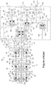
- the single Figure illustrates a gearbox assembly 10 comprising four successive subassemblies between an input shaft 11 coupled to the motor shaft, not shown, and an output shaft 13.
- the gearbox assembly 10 comprises thus: a system of staggered epicyclic trains 12; a transmission reduction module 14; a reversing module 15; and, two parallel clutch devices, a first 16 and a second 18.
- the input shaft 11 is extended through the system of stepped planetary gears 12 by a first hollow shaft section 20 which passes through a first internal sun gear 22 and is linked to a first planet carrier 24.
- the latter comprises a first set of satellites 26 meshing the first inner sun gear 22 and a first outer sun gear 28.
- This first group constitutes a first epicyclic gear train 30.
- the planetary planetary gear system 12 comprises a first locking device 32 allowing, in a released position, to couple in rotation the first internal sun gear 22 and the first door. Satellite 24, and in an active position, to maintain the first internal sun gear 22 in a fixed position while releasing the first planet carrier 24.
- the first outer sun gear 28 is integral with an intermediate hollow shaft section 34 extending coaxially in the extension of the first hollow shaft section 20 and passing through a second locking device 36 to join, symmetrically to the first outer sun gear 28, a second outer sun gear 38.
- Inside this second outer sun gear 38 engages a second set of planet gears 40 carried by a planet carrier 42 integral with a last hollow shaft section 44, which extends coaxially in the extension of the intermediate hollow shaft section 34.
- the second set of planet wheels 40 also engages a second inner planet gear 46 which is integral with a third planet gear carrier 48.
- the second inner planet gear 46 and the third planet carrier 48 are freely traversed by the last hollow shaft section 44.
- the third planet carrier 48 carries a third set of planet wheels 50, meshing with a third inner planet gear 52 and a third outer planet gear 54.
- the second locking device 36 makes it possible, in a released position, to couple in rotation the first outer sun gear 28 integral with the second outer sun gear 38 and the third outer sun gear 54, and in an active position to keep the third outer sun gear in a fixed position. 54, while the first outer sun gear 28 and the associated second outer sun gear 38 are free.
- the stepped planetary gear system 12 comprises a third locking device 56 allowing, in a released position, the last hollow shaft section 44 and the third inner sun gear 52 to be coupled in rotation. In an active position, the third locking device blocking 56 keeps the third inner sun gear 52 in a fixed position, while the last hollow shaft section 44 is free.
- first 22, second 46 and third 52 inner planets have the same number of teeth. It is for example between sixty-five and sixty-seven teeth.
- satellites of the first 26, second 40 and third 50 sets of satellites they present the same number of teeth, for example between seventeen and nineteen teeth.
- first 28, second 38 and third 54 outer planetary gear they also have the same number of teeth, advantageously between one hundred and one and one hundred and three teeth.
- the three blocking devices 32, 36 and 56 are likely to each be in two states, at rest, or active and therefore, all three devices can be in eight states. distinct. In practice, seven transmission ratios are used between the input shaft 11 and the last hollow shaft section 44.
- a first first gear ratio A corresponds to a state in which the first locking device 32 is at rest, while the second 36 and third 56 locking devices are active.
- a second first gear ratio B corresponds to a state in which the first 32 and third 56 blocking devices are at rest, while the second blocking device 36 is active.
- a third first gear ratio C corresponds to a state in which the first 32 and second 36 blocking devices are at rest, while the third blocking device 56 is active.
- a fourth first speed ratio D corresponds to a state in which the first 32, second 36 and third 56 blocking devices are at rest.
- a fifth first speed ratio E corresponds to a state in which the first 32 and second 36 blocking devices are active, while the third blocking device 56 is at rest.
- a sixth first speed ratio F corresponds to a state in which the first 32 and third 56 blocking devices are active, while the second blocking device 36 is at rest.
- a seventh first gear ratio G corresponds to a state in which the first blocking device 32 is active, while the second 36 and third 56 blocking devices are at rest.
- the last hollow shaft section 44 extends through the transmission reduction module 14 and ends with a last section coupling end 58.
- the transmission reduction module 14 has a hollow reduction shaft section 60 which extends coaxially in the extension of the last hollow shaft section 44 as far as the reversing module 15 which will be described below.
- the reduction hollow shaft section 60 has a reduction section coupling end 62 which extends opposite the last section coupling end 58.
- the last section coupling end 58 comprises in addition. rear, a small last reduction section wheel 64, while the reduction section coupling end 62 has at the rear, a large reduction section wheel 66 mounted idly.
- the transmission reduction module 14 comprises, on the one hand, a rotational coupling member 68 of the small wheel of the last reduction section 64 and of the large wheel of the reduction section 66, and on the other hand a device reduction coupling 70.
- the rotational coupling member 68 comprises a reduction shaft 72, extending parallel to the reduction hollow shaft section 60 and the last hollow shaft section 44, which reduction axis 72 comprises on the one hand a large reduction shaft wheel 74 meshing the small wheel of the last reduction section 64, and on the other hand a small reduction shaft wheel 76 meshing with the large reduction section wheel 66.
- the reduction coupling device 70 Quant to the reduction coupling device 70, it enables coupling, in a first position, the last section coupling end 58 directly with the reduction section coupling end 62, and in a second position, the 62 av reduction section coupling end ec the large reduction section wheel 66. Also, in the first coupling position of the reduction coupling device 70, the last section coupling end 58 directly engages the reduction section coupling end 62 without a reduction in rotational speed, while in the second coupling position, the reduction section coupling end 62 engages the reduction section large wheel 66. And in this second coupling position, count given the diameter ratios of the different wheels, or the tooth ratios of these wheels, a strong reduction in speed is obtained between the last hollow shaft section 44 and the reduction hollow shaft section 60.
- the small wheel of the last reduction section 64 comprises for example between twenty-five and twenty-seven teeth, while the large reduction section wheel 66 has between fifty-nine and sixty-one teeth, and on the other hand, the large reduction axle wheel 74 has between sixty and sixty-two teeth, while the small reduction axle wheel 76 has between thirteen and fifteen.
- the small wheel of the last reduction section 64 comprises for example between twenty-one and twenty-three teeth, while the large reduction section wheel 66 has between seventy and seventy-two teeth, and on the other hand, the large reduction axle wheel 74 has between seventy and seventy-two teeth, while the small wheel reduction axis 76 has between twenty-one and twenty-three.
- the reversing module 15 receives the hollow reduction shaft section 60 at the input, which is extended by a receiving shaft 75, and it comprises two reversing output wheels, a first reversing output wheel 78 and a second reversing output wheel 80.
- the two reversing output wheels 78, 80 are rotated in the same direction.
- the first reversing output wheel 78 is directly coupled to the two parallel clutch devices 16, 18, while the second reversing output wheel 80 is coupled thereto by via an inverting coupling member 82.
- the latter comprises a reverse coupling input wheel 91 meshing with the second inversion output wheel 80, and a reverse coupling output wheel 92.
- the second reversing output wheel 80 comprises, for example, between sixty-six and sixty-eight teeth
- the first reversing output wheel 78 comprises between forty-six and forty-eight teeth
- the wheel Reverse coupling input 91 comprises between thirty-three and thirty-five teeth
- the reverse coupling output wheel 92 comprises between twenty-three and twenty-five teeth.
- the transmission reduction module 14 is optional and therefore, when it is not installed in the gearbox assembly, the last hollow shaft section 44 is extended by the reception shaft 75 and joined thus directly the reversing module 15.
- the reverse gear module 15 is, according to an alternative embodiment, located upstream of the system of staggered epicyclic gears, and the input shaft then corresponds to the output of the reverser, while the gear shaft. reception is extended and ends with a wheel corresponding to the first inversion output wheel 78.
- first clutch device 16 As regards the first clutch device 16, it comprises a first input clutch wheel 84 mounted on a first input clutch shaft 86, a first controllable clutch 88 and a first output clutch shaft. 90. It will be seen that the first input clutch wheel 84 engages both the first reverse output wheel 78 and the reverse coupling output wheel 92 of the reverse coupling member 82.
- a first large high speed clutch wheel 94 is sluggishly mounted on the first output clutch shaft 90 and a first small low speed clutch wheel 96 is also slidably mounted on the first clutch shaft. output 90.
- a first clutch coupling device 98 is installed on the first output clutch shaft 90. This first clutch coupling device 98 is controllable in a first position where it comes from. to couple in rotation the first output clutch shaft 90 with the first large high speed clutch wheel 94. It is also controllable in a second position in which it rotates the first output clutch shaft 90 with the first small low speed clutch wheel 96.
- the first clutch coupling device 98 is, moreover, controllable in a neutral position, intermediate between the first and the second pos ition, in which it is free both with the first large high speed clutch wheel 94 and with the first small low speed clutch wheel 96.
- the, first input clutch wheel 84, first large high speed clutch wheel 94 and first small wheel Low speed clutch 96 include, for example, between fifty-nine and sixty-one teeth, between forty-six and forty-eight teeth, and between twenty and twenty-two teeth, respectively.
- the, first input clutch wheel 84, first large high speed clutch wheel 94, and first small clutch wheel 94 comprise, respectively, between sixty and sixty-two teeth, between thirty-six and thirty-eight teeth, and between twenty and twenty-two teeth.
- the second clutch device 18 comprises: a second input clutch wheel 100 mounted on a second input clutch shaft 102 and meshing the single first reverse output wheel 78, a second controllable clutch 104 and a second output clutch shaft 106.
- a second large high speed clutch wheel 108 is idle mounted on the second output clutch shaft 106, while a second small low speed clutch wheel 110 climbed there madly.
- a second clutch coupling device 112 is installed on the second output clutch shaft 106. It is controllable in a first position where it rotates the second output clutch shaft 106 with the second large high speed clutch wheel 108, and in a second position in which it rotates the second output clutch shaft 106 with the second small low speed clutch wheel 110.
- the second clutch coupling device 112 can also be controlled in a neutral position, between the first and the second position, making it possible to obtain the same effects.
- reverse coupling output wheel 92 of the reverse coupling member 82 in the Figure engages the first input clutch wheel 84, but it could equally well engage the second wheel. input clutch 100, without further modification to achieve the same functionality.
- the second input clutch wheel 100, second large high speed clutch wheel 108 and second small wheel low speed clutch 110 comprise, respectively, between twenty-five and twenty-seven teeth, between forty-six and forty-eight teeth and, between twenty and twenty-two teeth.
- the low speed clutch 110 have, respectively, between twenty-four and twenty-six teeth, between forty-four and forty-six teeth, and between twenty-five and twenty-seven teeth.
- the first embodiment according to which, for the two clutch devices 16, 18, the high speed clutch wheels 94, 108 have the same number of teeth as the low speed clutch wheels 96, 110, is advantageous in terms of standardization.
- the first input clutch wheel 84 of the first clutch device 16 has a number of teeth different from that of the second input clutch wheel 100 of the second clutch device 18, so as to be able to provide different second transmission ratios.
- Such a device makes it possible to design the same assembly, high speed clutch wheel / clutch coupling device / small low speed clutch wheel, and therefore at a more advantageous cost.
- the output shaft 13 is provided with a decoupling device 118, comprising a fixed wheel 115 integral with the output shaft 13 and a controllable coupling member 117 The latter is controllable between a coupling position, where it engages the fixed wheel 115 with the large low-speed output wheel 116 and hence, in which it rotatably couples the output shaft 13 and the large wheel. output low speed 116, and a decoupling position, where the fixed wheel 115 is free from the large low speed output wheel 116, and therefore, in which the large low speed output wheel 116 is free of charge. to the output shaft 13.
- a decoupling device 118 comprising a fixed wheel 115 integral with the output shaft 13 and a controllable coupling member 117
- the latter is controllable between a coupling position, where it engages the fixed wheel 115 with the large low-speed output wheel 116 and hence, in which it rotatably couples the output shaft 13 and the large wheel. output low speed 116, and a decoupling position, where the fixed
- the, high-speed small output wheel 114 and, low-speed large output wheel 116 for example comprise, respectively, between thirty -eight and forty teeth, and between seventy-seven and seventy-nine teeth.
- the, high speed small output wheel 114 and, large low speed output wheel 116 include, for example, respectively, between forty-two and forty-four teeth and between seventy-nine and eighty-one teeth.
- the large low speed output wheel 116 and hence the first and second small low speed clutch wheels 96, 110 can be released from the output shaft. 13, and therefore remain at rest, when the latter is driven at high speed through the small high speed output wheel 114.
- the coupling, and the module reverses drive 15 is in a forward drive position, i.e. As the first reverse output wheel 78 is driving, while the second clutch 104 is engaged, the speed of the output shaft 13 is maximum. Also, by uncoupling the large low speed output wheel 116 from the output shaft 13, the large low speed output wheel 116 and the first and second small low speed clutch wheels 96, 110 are brought to rest. If they are not brought to rest, their speeds are then very high and of the order of 20,000 rev / min. And in such circumstances, their wear is accelerated. Thus, thanks to the uncoupling, the first and second small low speed clutch wheels 96, 110 are preserved from premature aging.
- first and second small low speed clutch wheels 96, 110 are thus at rest over a wider range of speeds and therefore they are better preserved.
- the output shaft 13 has an output end terminated by a bevel pinion 120 so as to be able to be mechanically connected to a differential, not shown.
- the output shaft is also equipped with an output wheel 122 intended to be rotatably coupled to a drive shaft of other wheels 124 by means of a four-wheel drive clutch 126.
- the latter has a input wheel 125.
- the output wheel 122 and input wheel 125 for example comprise, respectively, between thirty-four and thirty-six teeth and between sixty-five and sixty-seven teeth.
- the output wheel 122 and input wheel 125 comprise for example, respectively, between thirty-three and thirty-five and between sixty-six and sixty-eight teeth.
- the output wheel 122 and input wheel 125 for example comprise, respectively, between forty -seven and forty-nine and, between seventy-seven and seventy-nine teeth.
- the output wheel 122 and input wheel 125 comprise, for example, respectively, between thirty-nine and forty-one and between sixty-seven and sixty-nine teeth.
- the gearbox assembly 10 comprises a motor shaft 128, coupled for example directly to the input shaft 11, and which passes axially and freely through the stepped planetary gear system 12, the transmission reduction module 14 and the reversing module 15, and this successively through: the first hollow shaft section 20, the intermediate hollow shaft section 34, the last hollow shaft section 44, the reduction hollow shaft section 60 in order to be able to come out to the right of the two parallel clutch devices 16, 18. Thanks to the motor shaft 128, it is possible to drive in particular the hydraulic pumps, not shown, by means of drive members located not in the extension axial parallel clutch devices 16, 18, but substantially to the right of the controllable clutches 88, 104.
- these drive members include a pump drive wheel 130 coupled to the motor shaft 128 by means of 'a wheel
- the transfer 132 madly mounted on the second output clutch shaft 106, between the second controllable clutch 104 and the second large high speed clutch wheel 108, which transfer wheel 132 meshes with a transmission wheel 134 integral with the motor shaft 128.
- the gearbox assembly is substantially shortened axially. This possibility is offered to us because the second controllable clutch 104 is shorter than the first 88 and it thus makes it possible to free up a space to mount the transfer wheel 132.
- the pump drive wheel 130, transfer wheel 132 and transmission wheel 134 comprise, for example and respectively, between twenty-four and twenty-six teeth, between fifty-three and fifty-six teeth and, between thirty-four and thirty-six teeth.
Landscapes
- Engineering & Computer Science (AREA)
- General Engineering & Computer Science (AREA)
- Mechanical Engineering (AREA)
- Life Sciences & Earth Sciences (AREA)
- Soil Sciences (AREA)
- Environmental Sciences (AREA)
- Structure Of Transmissions (AREA)
Claims (10)
- Getriebeanordnung (10) für ein motorisiertes landwirtschaftliches Fahrzeug, umfassend:- ein System gestufter Umlaufrädergetriebe (12), um eine Vielzahl von ersten Übersetzungsverhältnissen bereitzustellen;- eine Kupplungsvorrichtung (16), umfassend eine Eingangskupplungswelle (86), die an das System gestufter Umlaufrädergetriebe (12) gekuppelt ist, und eine Ausgangskupplungswelle (90);- ein großes Kupplungsrad hoher Geschwindigkeit (94) und ein kleines Kupplungsrad niedriger Geschwindigkeit (96), die freilaufend auf der Ausgangskupplungswelle (90) angebracht sind, um zwei zweite Übersetzungsverhältnisse bereitstellen zu können;- eine Kupplungseinkupplungsvorrichtung (98), um das eine oder das andere der Räder niedriger (96) und hoher (94) Geschwindigkeit mit der Ausgangskupplungswelle (90) kuppeln zu können;- eine Ausgangswelle (13), umfassend ein kleines Ausgangsrad hoher Geschwindigkeit (114), das mit dem großen Kupplungsrad hoher Geschwindigkeit (94) in Eingriff ist, und ein großes Ausgangsrad niedriger Geschwindigkeit (116), das mit dem kleinen Kupplungsrad niedriger Geschwindigkeit (96) in Eingriff ist;dadurch gekennzeichnet, dass sie ferner eine Auskupplungsvorrichtung (118) zwischen der Ausgangswelle (13) und dem großen Ausgangsrad niedriger Geschwindigkeit (116) umfasst, um die Ausgangswelle (13) von dem kleinen Kupplungsrad niedriger Geschwindigkeit (96) auszurücken.
- Getriebeanordnung nach Anspruch 1, dadurch gekennzeichnet, dass das große Ausgangsrad niedriger Geschwindigkeit (116) freilaufend auf der Ausgangswelle (13) angebracht ist.
- Getriebeanordnung nach Anspruch 1, dadurch gekennzeichnet, dass die Auskupplungsvorrichtung (118) ein starr angebrachtes Rad der Ausgangswelle (13) und ein fest verbundenes Kupplungselement des Festrads umfasst, das gesteuert werden kann, um das Festrad und das große Ausgangsrad niedriger Geschwindigkeit (116) in Eingriff zu bringen.
- Getriebeanordnung nach einem beliebigen der Ansprüche 1 bis 3, dadurch gekennzeichnet, dass die Kupplungsvorrichtung (16) eine steuerbare Kupplung (88) umfasst, die sich zwischen der Kupplungseingangswelle (86) und der Ausgangskupplungswelle (90) befindet.
- Getriebeanordnung nach einem beliebigen der Ansprüche 1 bis 4, dadurch gekennzeichnet, dass sie ferner umfasst:- eine weitere Kupplungsvorrichtung (18), umfassend eine weitere Eingangskupplungswelle (102), die an das System von Umlaufrädergetrieben (12) gekuppelt ist, und eine weitere Ausgangskupplungswelle (106);- ein weiteres großes Kupplungsrad hoher Geschwindigkeit (108) und ein weiteres kleines Kupplungsrad niedriger Geschwindigkeit (110), die freilaufend auf der weiteren Ausgangskupplungswelle (106) angebracht sind, um zwei weitere zweite Übersetzungsverhältnisse bereitstellen zu können, wobei die weiteren großen (108) und kleinen (110) Kupplungsräder hoher und niedriger Geschwindigkeit jeweils mit den kleinen (114) und großen (116) Ausgangsrädern hoher und niedriger Geschwindigkeit in Eingriff sind; und- eine weitere Kupplungseinkupplungsvorrichtung (112), um das eine oder das andere der weiteren Räder niedriger (110) und hoher (108) Geschwindigkeit mit der weiteren Ausgangskupplungswelle (106) kuppeln zu können.
- Getriebeanordnung nach Anspruch 5, dadurch gekennzeichnet, dass die weitere Kupplungsvorrichtung (18) eine weitere steuerbare Kupplung (104) umfasst, die sich zwischen der weiteren Eingangskupplungswelle (102) und der weiteren Ausgangskupplungswelle (106) befindet.
- Getriebeanordnung nach einem beliebigen der Ansprüche 1 bis 6, dadurch gekennzeichnet, dass sie ferner ein Umkehrmodul (15) umfasst, das sich zwischen dem System gestufter Umlaufrädergetriebe (12) und der Kupplungsvorrichtung (16) befindet, um die Drehrichtung der Eingangswelle (86, 102) umkehren zu können.
- Getriebeanordnung nach Anspruch 7, dadurch gekennzeichnet, dass das Umkehrmodul (15) einerseits eine Aufnahmewelle (75), die an das System gestufter Umlaufrädergetriebe (12) gekuppelt ist, und andererseits zwei Umkehrräder (78, 80), die freilaufend auf der Aufnahmewelle (75) angebracht sind, und zwei Umkehrkupplungen umfasst, um alternativ die beiden Umkehrräder (78, 80) an die Kupplungsvorrichtung kuppeln zu können.
- Getriebeanordnung nach einem beliebigen der Ansprüche 1 bis 8, dadurch gekennzeichnet, dass sie ferner ein Untersetzungsgetriebemodul (14) umfasst, das sich zwischen dem System gestufter Umlaufrädergetriebe (12) und der Kupplungsvorrichtung (16) befindet, um die Übersetzungsverhältnisse der Vielzahl von Übersetzungsverhältnissen reduzieren zu können.
- Getriebeanordnung nach einem beliebigen der Ansprüche 1 bis 9, dadurch gekennzeichnet, dass das System gestufter Umlaufrädergetriebe (12) drei Sätze von Sonnen- und Hohlrädern (22, 28; 46, 38; 52, 54) und drei Sätze von Umlaufrädern (26; 40; 50) umfasst, die jeweils in den drei Sätzen von Sonnen- und Hohlrädern (22, 28; 46, 38; 52, 54) angebracht sind.
Applications Claiming Priority (2)
| Application Number | Priority Date | Filing Date | Title |
|---|---|---|---|
| FR1559579A FR3042248B1 (fr) | 2015-10-08 | 2015-10-08 | Ensemble de boite de vitesses pour vehicule agricole a large gamme de vitesses |
| PCT/FR2016/052593 WO2017060645A1 (fr) | 2015-10-08 | 2016-10-07 | Ensemble de boite de vitesses pour vehicule agricole a large gamme de vitesses |
Publications (2)
| Publication Number | Publication Date |
|---|---|
| EP3359847A1 EP3359847A1 (de) | 2018-08-15 |
| EP3359847B1 true EP3359847B1 (de) | 2020-10-21 |
Family
ID=54783848
Family Applications (1)
| Application Number | Title | Priority Date | Filing Date |
|---|---|---|---|
| EP16788737.1A Active EP3359847B1 (de) | 2015-10-08 | 2016-10-07 | Getriebeanordnung für ein landwirtschaftliches fahrzeug mit breitem geschwindigkeitsbereich |
Country Status (6)
| Country | Link |
|---|---|
| US (1) | US10641372B2 (de) |
| EP (1) | EP3359847B1 (de) |
| CN (1) | CN108351005B (de) |
| ES (1) | ES2842406T3 (de) |
| FR (1) | FR3042248B1 (de) |
| WO (1) | WO2017060645A1 (de) |
Families Citing this family (2)
| Publication number | Priority date | Publication date | Assignee | Title |
|---|---|---|---|---|
| EP4249766A3 (de) * | 2020-09-01 | 2023-11-08 | Deere & Company | Getriebeeinheit, getriebeanordnung und landwirtschaftliches zugfahrzeug |
| EP4105515B1 (de) * | 2021-06-16 | 2025-08-13 | Deere & Company | Getriebe und landwirtschaftliches oder industrielles nutzfahrzeug |
Family Cites Families (8)
| Publication number | Priority date | Publication date | Assignee | Title |
|---|---|---|---|---|
| DE3414107A1 (de) * | 1984-04-13 | 1985-10-24 | Rudolf Prof. Dr.-Ing. 6100 Darmstadt Franke | Unter last schaltbares stirnradwechselgetriebe |
| EP0899145B1 (de) * | 1997-09-01 | 2004-08-04 | Kanzaki Kokyukoki Mfg. Co., Ltd. | Getriebemechanismus für ein Arbeitsfahrzeug |
| CA2283703A1 (en) * | 1998-01-16 | 1999-07-22 | Joachim Horsch | Multispeed powershift transmission |
| US7166049B2 (en) * | 2004-12-28 | 2007-01-23 | Agco Gmbh | Vehicle drive and a control method for a vehicle drive |
| CN2833258Y (zh) * | 2005-03-31 | 2006-11-01 | 中国农业大学 | 一种汽车变速器换挡机构 |
| CN101450609B (zh) * | 2007-11-30 | 2012-09-05 | 比亚迪股份有限公司 | 混合动力驱动系统及其驱动方法 |
| CN102606687A (zh) * | 2012-03-22 | 2012-07-25 | 同济大学 | 提高两轴式变速箱传动效率的传动装置 |
| DE102013110709A1 (de) * | 2013-09-27 | 2015-04-02 | CLAAS Tractor S.A.S | Schaltgetriebeanordnung |
-
2015
- 2015-10-08 FR FR1559579A patent/FR3042248B1/fr active Active
-
2016
- 2016-10-07 WO PCT/FR2016/052593 patent/WO2017060645A1/fr not_active Ceased
- 2016-10-07 EP EP16788737.1A patent/EP3359847B1/de active Active
- 2016-10-07 US US15/765,313 patent/US10641372B2/en active Active
- 2016-10-07 ES ES16788737T patent/ES2842406T3/es active Active
- 2016-10-07 CN CN201680065249.8A patent/CN108351005B/zh active Active
Non-Patent Citations (1)
| Title |
|---|
| None * |
Also Published As
| Publication number | Publication date |
|---|---|
| US20180306292A1 (en) | 2018-10-25 |
| CN108351005A (zh) | 2018-07-31 |
| EP3359847A1 (de) | 2018-08-15 |
| US10641372B2 (en) | 2020-05-05 |
| ES2842406T3 (es) | 2021-07-14 |
| FR3042248A1 (fr) | 2017-04-14 |
| FR3042248B1 (fr) | 2017-12-15 |
| WO2017060645A1 (fr) | 2017-04-13 |
| CN108351005B (zh) | 2021-09-21 |
Similar Documents
| Publication | Publication Date | Title |
|---|---|---|
| EP3019771B1 (de) | Integration eines getriebezugs in eine ritzelwand in einem getriebe für eine turbomaschine | |
| EP3019708B1 (de) | Kompakte struktur für ein hilfsgetriebe eines flugzeugturbinentriebwerks | |
| FR2973334A1 (fr) | Actionneur rotatif a haute integrite et procede de commande | |
| FR2976526A1 (fr) | Groupe motopropulseur | |
| WO2011073590A1 (fr) | Systeme de motorisation electrique d'une roue | |
| EP3365544B1 (de) | Wärmekraftmaschine mit system zur veränderung der verdichtung | |
| WO2005103525A1 (fr) | 'boite de vitesses pour l'automobile, notamment a double embrayage' | |
| WO2011148065A1 (fr) | Boite de vitesses a double embrayage comportant une liaison de transfert et un rapport de marche arriere | |
| EP0300905A1 (de) | Untersetzungsgetriebe mit parallelen oder rechtwinkligen Achsen und Leistungsverzweigung und Spielausgleich | |
| EP3359847B1 (de) | Getriebeanordnung für ein landwirtschaftliches fahrzeug mit breitem geschwindigkeitsbereich | |
| CA2980430A1 (fr) | Reducteur de vitesse a deux lignes intermediaires de transmission | |
| EP3416886B1 (de) | Untersetzungsgetriebe mit ein-/ausgabedrehungsumkehr | |
| EP4339099A1 (de) | Untersetzungsgetriebe für eine antriebsvorrichtung eines rades eines flugzeugfahrwerks | |
| FR3100756A1 (fr) | Transmission hybride comportant un train planetaire et des crabots | |
| EP4339097A1 (de) | Vorrichtung zum antrieb mindestens eines rades eines flugzeugfahrwerks | |
| FR3077108A1 (fr) | Boite de vitesses a double embrayage comportant une liaison de transfert entre les deux arbres primaires | |
| WO2007000521A2 (fr) | Systeme de boite de vitesses a trains epicycloidaux | |
| FR3010164A1 (fr) | Boite de vitesses a double embrayage pour un vehicule automobile | |
| FR3106089A1 (fr) | Transmission automatique pour véhicule hybride thermique/électrique | |
| FR2861447A1 (fr) | Boite de vitesse pour vehicule automobile. | |
| WO2015028726A1 (fr) | Transmission a variation continue avec recirculation de puissance | |
| FR3010165A1 (fr) | Boite de vitesses a double embrayage pour un vehicule automobile | |
| FR3104499A1 (fr) | Groupe motopropulseur transversal de vehicule automobile a boite de vitesses decalee en face avant ou en face arriere du moteur, et a double embrayage | |
| BE510189A (de) | ||
| FR3086894A1 (fr) | Transmission a un embrayage et deux voies de puissance delivrant un couple sur un train planetaire |
Legal Events
| Date | Code | Title | Description |
|---|---|---|---|
| STAA | Information on the status of an ep patent application or granted ep patent |
Free format text: STATUS: UNKNOWN |
|
| STAA | Information on the status of an ep patent application or granted ep patent |
Free format text: STATUS: THE INTERNATIONAL PUBLICATION HAS BEEN MADE |
|
| PUAI | Public reference made under article 153(3) epc to a published international application that has entered the european phase |
Free format text: ORIGINAL CODE: 0009012 |
|
| STAA | Information on the status of an ep patent application or granted ep patent |
Free format text: STATUS: REQUEST FOR EXAMINATION WAS MADE |
|
| 17P | Request for examination filed |
Effective date: 20180508 |
|
| AK | Designated contracting states |
Kind code of ref document: A1 Designated state(s): AL AT BE BG CH CY CZ DE DK EE ES FI FR GB GR HR HU IE IS IT LI LT LU LV MC MK MT NL NO PL PT RO RS SE SI SK SM TR |
|
| AX | Request for extension of the european patent |
Extension state: BA ME |
|
| DAV | Request for validation of the european patent (deleted) | ||
| DAX | Request for extension of the european patent (deleted) | ||
| GRAP | Despatch of communication of intention to grant a patent |
Free format text: ORIGINAL CODE: EPIDOSNIGR1 |
|
| STAA | Information on the status of an ep patent application or granted ep patent |
Free format text: STATUS: GRANT OF PATENT IS INTENDED |
|
| INTG | Intention to grant announced |
Effective date: 20200515 |
|
| GRAS | Grant fee paid |
Free format text: ORIGINAL CODE: EPIDOSNIGR3 |
|
| GRAA | (expected) grant |
Free format text: ORIGINAL CODE: 0009210 |
|
| STAA | Information on the status of an ep patent application or granted ep patent |
Free format text: STATUS: THE PATENT HAS BEEN GRANTED |
|
| AK | Designated contracting states |
Kind code of ref document: B1 Designated state(s): AL AT BE BG CH CY CZ DE DK EE ES FI FR GB GR HR HU IE IS IT LI LT LU LV MC MK MT NL NO PL PT RO RS SE SI SK SM TR |
|
| REG | Reference to a national code |
Ref country code: GB Ref legal event code: FG4D Free format text: NOT ENGLISH |
|
| REG | Reference to a national code |
Ref country code: CH Ref legal event code: EP |
|
| REG | Reference to a national code |
Ref country code: IE Ref legal event code: FG4D Free format text: LANGUAGE OF EP DOCUMENT: FRENCH |
|
| REG | Reference to a national code |
Ref country code: DE Ref legal event code: R096 Ref document number: 602016046332 Country of ref document: DE |
|
| REG | Reference to a national code |
Ref country code: AT Ref legal event code: REF Ref document number: 1326151 Country of ref document: AT Kind code of ref document: T Effective date: 20201115 |
|
| REG | Reference to a national code |
Ref country code: FI Ref legal event code: FGE |
|
| REG | Reference to a national code |
Ref country code: NL Ref legal event code: MP Effective date: 20201021 |
|
| PG25 | Lapsed in a contracting state [announced via postgrant information from national office to epo] |
Ref country code: PT Free format text: LAPSE BECAUSE OF FAILURE TO SUBMIT A TRANSLATION OF THE DESCRIPTION OR TO PAY THE FEE WITHIN THE PRESCRIBED TIME-LIMIT Effective date: 20210222 Ref country code: RS Free format text: LAPSE BECAUSE OF FAILURE TO SUBMIT A TRANSLATION OF THE DESCRIPTION OR TO PAY THE FEE WITHIN THE PRESCRIBED TIME-LIMIT Effective date: 20201021 Ref country code: NO Free format text: LAPSE BECAUSE OF FAILURE TO SUBMIT A TRANSLATION OF THE DESCRIPTION OR TO PAY THE FEE WITHIN THE PRESCRIBED TIME-LIMIT Effective date: 20210121 Ref country code: GR Free format text: LAPSE BECAUSE OF FAILURE TO SUBMIT A TRANSLATION OF THE DESCRIPTION OR TO PAY THE FEE WITHIN THE PRESCRIBED TIME-LIMIT Effective date: 20210122 |
|
| REG | Reference to a national code |
Ref country code: LT Ref legal event code: MG4D |
|
| PG25 | Lapsed in a contracting state [announced via postgrant information from national office to epo] |
Ref country code: SE Free format text: LAPSE BECAUSE OF FAILURE TO SUBMIT A TRANSLATION OF THE DESCRIPTION OR TO PAY THE FEE WITHIN THE PRESCRIBED TIME-LIMIT Effective date: 20201021 Ref country code: BG Free format text: LAPSE BECAUSE OF FAILURE TO SUBMIT A TRANSLATION OF THE DESCRIPTION OR TO PAY THE FEE WITHIN THE PRESCRIBED TIME-LIMIT Effective date: 20210121 Ref country code: IS Free format text: LAPSE BECAUSE OF FAILURE TO SUBMIT A TRANSLATION OF THE DESCRIPTION OR TO PAY THE FEE WITHIN THE PRESCRIBED TIME-LIMIT Effective date: 20210221 Ref country code: LV Free format text: LAPSE BECAUSE OF FAILURE TO SUBMIT A TRANSLATION OF THE DESCRIPTION OR TO PAY THE FEE WITHIN THE PRESCRIBED TIME-LIMIT Effective date: 20201021 Ref country code: PL Free format text: LAPSE BECAUSE OF FAILURE TO SUBMIT A TRANSLATION OF THE DESCRIPTION OR TO PAY THE FEE WITHIN THE PRESCRIBED TIME-LIMIT Effective date: 20201021 |
|
| PG25 | Lapsed in a contracting state [announced via postgrant information from national office to epo] |
Ref country code: NL Free format text: LAPSE BECAUSE OF FAILURE TO SUBMIT A TRANSLATION OF THE DESCRIPTION OR TO PAY THE FEE WITHIN THE PRESCRIBED TIME-LIMIT Effective date: 20201021 Ref country code: HR Free format text: LAPSE BECAUSE OF FAILURE TO SUBMIT A TRANSLATION OF THE DESCRIPTION OR TO PAY THE FEE WITHIN THE PRESCRIBED TIME-LIMIT Effective date: 20201021 |
|
| REG | Reference to a national code |
Ref country code: ES Ref legal event code: FG2A Ref document number: 2842406 Country of ref document: ES Kind code of ref document: T3 Effective date: 20210714 |
|
| REG | Reference to a national code |
Ref country code: DE Ref legal event code: R097 Ref document number: 602016046332 Country of ref document: DE |
|
| PG25 | Lapsed in a contracting state [announced via postgrant information from national office to epo] |
Ref country code: SK Free format text: LAPSE BECAUSE OF FAILURE TO SUBMIT A TRANSLATION OF THE DESCRIPTION OR TO PAY THE FEE WITHIN THE PRESCRIBED TIME-LIMIT Effective date: 20201021 Ref country code: RO Free format text: LAPSE BECAUSE OF FAILURE TO SUBMIT A TRANSLATION OF THE DESCRIPTION OR TO PAY THE FEE WITHIN THE PRESCRIBED TIME-LIMIT Effective date: 20201021 Ref country code: SM Free format text: LAPSE BECAUSE OF FAILURE TO SUBMIT A TRANSLATION OF THE DESCRIPTION OR TO PAY THE FEE WITHIN THE PRESCRIBED TIME-LIMIT Effective date: 20201021 Ref country code: LT Free format text: LAPSE BECAUSE OF FAILURE TO SUBMIT A TRANSLATION OF THE DESCRIPTION OR TO PAY THE FEE WITHIN THE PRESCRIBED TIME-LIMIT Effective date: 20201021 Ref country code: EE Free format text: LAPSE BECAUSE OF FAILURE TO SUBMIT A TRANSLATION OF THE DESCRIPTION OR TO PAY THE FEE WITHIN THE PRESCRIBED TIME-LIMIT Effective date: 20201021 |
|
| PLBE | No opposition filed within time limit |
Free format text: ORIGINAL CODE: 0009261 |
|
| STAA | Information on the status of an ep patent application or granted ep patent |
Free format text: STATUS: NO OPPOSITION FILED WITHIN TIME LIMIT |
|
| PG25 | Lapsed in a contracting state [announced via postgrant information from national office to epo] |
Ref country code: DK Free format text: LAPSE BECAUSE OF FAILURE TO SUBMIT A TRANSLATION OF THE DESCRIPTION OR TO PAY THE FEE WITHIN THE PRESCRIBED TIME-LIMIT Effective date: 20201021 |
|
| 26N | No opposition filed |
Effective date: 20210722 |
|
| PG25 | Lapsed in a contracting state [announced via postgrant information from national office to epo] |
Ref country code: AL Free format text: LAPSE BECAUSE OF FAILURE TO SUBMIT A TRANSLATION OF THE DESCRIPTION OR TO PAY THE FEE WITHIN THE PRESCRIBED TIME-LIMIT Effective date: 20201021 |
|
| PG25 | Lapsed in a contracting state [announced via postgrant information from national office to epo] |
Ref country code: SI Free format text: LAPSE BECAUSE OF FAILURE TO SUBMIT A TRANSLATION OF THE DESCRIPTION OR TO PAY THE FEE WITHIN THE PRESCRIBED TIME-LIMIT Effective date: 20201021 |
|
| REG | Reference to a national code |
Ref country code: CH Ref legal event code: PL |
|
| PG25 | Lapsed in a contracting state [announced via postgrant information from national office to epo] |
Ref country code: IS Free format text: LAPSE BECAUSE OF FAILURE TO SUBMIT A TRANSLATION OF THE DESCRIPTION OR TO PAY THE FEE WITHIN THE PRESCRIBED TIME-LIMIT Effective date: 20210221 |
|
| REG | Reference to a national code |
Ref country code: BE Ref legal event code: MM Effective date: 20211031 |
|
| PG25 | Lapsed in a contracting state [announced via postgrant information from national office to epo] |
Ref country code: LU Free format text: LAPSE BECAUSE OF NON-PAYMENT OF DUE FEES Effective date: 20211007 Ref country code: BE Free format text: LAPSE BECAUSE OF NON-PAYMENT OF DUE FEES Effective date: 20211031 |
|
| PG25 | Lapsed in a contracting state [announced via postgrant information from national office to epo] |
Ref country code: LI Free format text: LAPSE BECAUSE OF NON-PAYMENT OF DUE FEES Effective date: 20211031 Ref country code: CH Free format text: LAPSE BECAUSE OF NON-PAYMENT OF DUE FEES Effective date: 20211031 |
|
| REG | Reference to a national code |
Ref country code: AT Ref legal event code: UEP Ref document number: 1326151 Country of ref document: AT Kind code of ref document: T Effective date: 20201021 |
|
| PG25 | Lapsed in a contracting state [announced via postgrant information from national office to epo] |
Ref country code: IE Free format text: LAPSE BECAUSE OF NON-PAYMENT OF DUE FEES Effective date: 20211007 |
|
| PG25 | Lapsed in a contracting state [announced via postgrant information from national office to epo] |
Ref country code: HU Free format text: LAPSE BECAUSE OF FAILURE TO SUBMIT A TRANSLATION OF THE DESCRIPTION OR TO PAY THE FEE WITHIN THE PRESCRIBED TIME-LIMIT; INVALID AB INITIO Effective date: 20161007 |
|
| PG25 | Lapsed in a contracting state [announced via postgrant information from national office to epo] |
Ref country code: CY Free format text: LAPSE BECAUSE OF FAILURE TO SUBMIT A TRANSLATION OF THE DESCRIPTION OR TO PAY THE FEE WITHIN THE PRESCRIBED TIME-LIMIT Effective date: 20201021 |
|
| PG25 | Lapsed in a contracting state [announced via postgrant information from national office to epo] |
Ref country code: MK Free format text: LAPSE BECAUSE OF FAILURE TO SUBMIT A TRANSLATION OF THE DESCRIPTION OR TO PAY THE FEE WITHIN THE PRESCRIBED TIME-LIMIT Effective date: 20201021 |
|
| PG25 | Lapsed in a contracting state [announced via postgrant information from national office to epo] |
Ref country code: TR Free format text: LAPSE BECAUSE OF FAILURE TO SUBMIT A TRANSLATION OF THE DESCRIPTION OR TO PAY THE FEE WITHIN THE PRESCRIBED TIME-LIMIT Effective date: 20201021 |
|
| PG25 | Lapsed in a contracting state [announced via postgrant information from national office to epo] |
Ref country code: MT Free format text: LAPSE BECAUSE OF FAILURE TO SUBMIT A TRANSLATION OF THE DESCRIPTION OR TO PAY THE FEE WITHIN THE PRESCRIBED TIME-LIMIT Effective date: 20201021 |
|
| PGFP | Annual fee paid to national office [announced via postgrant information from national office to epo] |
Ref country code: DE Payment date: 20251021 Year of fee payment: 10 |
|
| PGFP | Annual fee paid to national office [announced via postgrant information from national office to epo] |
Ref country code: GB Payment date: 20251022 Year of fee payment: 10 |
|
| PGFP | Annual fee paid to national office [announced via postgrant information from national office to epo] |
Ref country code: MC Payment date: 20251023 Year of fee payment: 10 |
|
| PGFP | Annual fee paid to national office [announced via postgrant information from national office to epo] |
Ref country code: AT Payment date: 20251022 Year of fee payment: 10 |
|
| PGFP | Annual fee paid to national office [announced via postgrant information from national office to epo] |
Ref country code: FI Payment date: 20251028 Year of fee payment: 10 Ref country code: IT Payment date: 20251024 Year of fee payment: 10 |
|
| PGFP | Annual fee paid to national office [announced via postgrant information from national office to epo] |
Ref country code: FR Payment date: 20251029 Year of fee payment: 10 |
|
| PGFP | Annual fee paid to national office [announced via postgrant information from national office to epo] |
Ref country code: CZ Payment date: 20251002 Year of fee payment: 10 |
|
| PGFP | Annual fee paid to national office [announced via postgrant information from national office to epo] |
Ref country code: ES Payment date: 20251216 Year of fee payment: 10 |