EP3358823B1 - Verfahren und vorrichtung zur umschaltung zwischen betriebsmodi einer videoüberwachungsvorrichtung - Google Patents
Verfahren und vorrichtung zur umschaltung zwischen betriebsmodi einer videoüberwachungsvorrichtung Download PDFInfo
- Publication number
- EP3358823B1 EP3358823B1 EP16869756.3A EP16869756A EP3358823B1 EP 3358823 B1 EP3358823 B1 EP 3358823B1 EP 16869756 A EP16869756 A EP 16869756A EP 3358823 B1 EP3358823 B1 EP 3358823B1
- Authority
- EP
- European Patent Office
- Prior art keywords
- operation mode
- target
- mode
- current operation
- video surveillance
- Prior art date
- Legal status (The legal status is an assumption and is not a legal conclusion. Google has not performed a legal analysis and makes no representation as to the accuracy of the status listed.)
- Active
Links
Images
Classifications
-
- H—ELECTRICITY
- H04—ELECTRIC COMMUNICATION TECHNIQUE
- H04N—PICTORIAL COMMUNICATION, e.g. TELEVISION
- H04N23/00—Cameras or camera modules comprising electronic image sensors; Control thereof
- H04N23/60—Control of cameras or camera modules
- H04N23/667—Camera operation mode switching, e.g. between still and video, sport and normal or high- and low-resolution modes
-
- H—ELECTRICITY
- H04—ELECTRIC COMMUNICATION TECHNIQUE
- H04N—PICTORIAL COMMUNICATION, e.g. TELEVISION
- H04N23/00—Cameras or camera modules comprising electronic image sensors; Control thereof
- H04N23/10—Cameras or camera modules comprising electronic image sensors; Control thereof for generating image signals from different wavelengths
- H04N23/11—Cameras or camera modules comprising electronic image sensors; Control thereof for generating image signals from different wavelengths for generating image signals from visible and infrared light wavelengths
-
- H—ELECTRICITY
- H04—ELECTRIC COMMUNICATION TECHNIQUE
- H04N—PICTORIAL COMMUNICATION, e.g. TELEVISION
- H04N23/00—Cameras or camera modules comprising electronic image sensors; Control thereof
- H04N23/70—Circuitry for compensating brightness variation in the scene
-
- H—ELECTRICITY
- H04—ELECTRIC COMMUNICATION TECHNIQUE
- H04N—PICTORIAL COMMUNICATION, e.g. TELEVISION
- H04N23/00—Cameras or camera modules comprising electronic image sensors; Control thereof
- H04N23/70—Circuitry for compensating brightness variation in the scene
- H04N23/71—Circuitry for evaluating the brightness variation
-
- H—ELECTRICITY
- H04—ELECTRIC COMMUNICATION TECHNIQUE
- H04N—PICTORIAL COMMUNICATION, e.g. TELEVISION
- H04N23/00—Cameras or camera modules comprising electronic image sensors; Control thereof
- H04N23/70—Circuitry for compensating brightness variation in the scene
- H04N23/72—Combination of two or more compensation controls
-
- H—ELECTRICITY
- H04—ELECTRIC COMMUNICATION TECHNIQUE
- H04N—PICTORIAL COMMUNICATION, e.g. TELEVISION
- H04N23/00—Cameras or camera modules comprising electronic image sensors; Control thereof
- H04N23/70—Circuitry for compensating brightness variation in the scene
- H04N23/73—Circuitry for compensating brightness variation in the scene by influencing the exposure time
-
- H—ELECTRICITY
- H04—ELECTRIC COMMUNICATION TECHNIQUE
- H04N—PICTORIAL COMMUNICATION, e.g. TELEVISION
- H04N23/00—Cameras or camera modules comprising electronic image sensors; Control thereof
- H04N23/70—Circuitry for compensating brightness variation in the scene
- H04N23/76—Circuitry for compensating brightness variation in the scene by influencing the image signals
-
- G—PHYSICS
- G06—COMPUTING OR CALCULATING; COUNTING
- G06T—IMAGE DATA PROCESSING OR GENERATION, IN GENERAL
- G06T2207/00—Indexing scheme for image analysis or image enhancement
- G06T2207/10—Image acquisition modality
- G06T2207/10016—Video; Image sequence
-
- G—PHYSICS
- G06—COMPUTING OR CALCULATING; COUNTING
- G06T—IMAGE DATA PROCESSING OR GENERATION, IN GENERAL
- G06T2207/00—Indexing scheme for image analysis or image enhancement
- G06T2207/10—Image acquisition modality
- G06T2207/10048—Infrared image
-
- G—PHYSICS
- G06—COMPUTING OR CALCULATING; COUNTING
- G06T—IMAGE DATA PROCESSING OR GENERATION, IN GENERAL
- G06T2207/00—Indexing scheme for image analysis or image enhancement
- G06T2207/30—Subject of image; Context of image processing
- G06T2207/30232—Surveillance
-
- G—PHYSICS
- G06—COMPUTING OR CALCULATING; COUNTING
- G06T—IMAGE DATA PROCESSING OR GENERATION, IN GENERAL
- G06T7/00—Image analysis
- G06T7/20—Analysis of motion
-
- G—PHYSICS
- G06—COMPUTING OR CALCULATING; COUNTING
- G06T—IMAGE DATA PROCESSING OR GENERATION, IN GENERAL
- G06T7/00—Image analysis
- G06T7/50—Depth or shape recovery
Definitions
- the present disclosure relates to the technical field of a video surveillance device and particularly relates to switching between operation modes of a video surveillance device.
- Video monitoring which is an important part of a security protection system, has been widely used in many occasions because of its visuality, accuracy, promptness and richness in information contents.
- Video monitoring which is an important part of a security protection system, has been widely used in many occasions because of its visuality, accuracy, promptness and richness in information contents.
- the trend of popularization of video monitoring is becoming more and more apparent.
- PIR Passive Infrared
- a PIR camera may switch to a black/white mode and automatically turn on an infrared lamp.
- the PIR camera may automatically switch to a color mode to take a photograph or record a video.
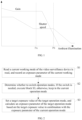
- an exposure parameter may be adjusted from the right end or some special point of an exposure line as a starting point.
- the exposure line refers to a sequence in which exposure elements such as shutter speed, aperture, gain and the like are adjusted during an exposure adjustment.
- a point Pa corresponds to an exposure parameter that should be used in a color mode, and the exposure parameter may be adjusted by starting from the right end or a special point Pb of the exposure line to gradually approximate to the point Pa through light metering and exposure calculation.
- the light metering and the exposure calculation may take time, a monitored target may leave a monitoring range before the exposure calculation is completed, resulting in that the monitored target cannot be captured a color image in time.
- CN 101893 804 A discloses a capture machine.
- the capture machine of D1 is applied to the field of traffic surveillance, for example, city red light rush enforcement, city traffic crossroads, and ramp entrance, and uses a different technology from a PIR technology.
- the exposure parameters are set for a video-recording mode and a capture mode, not set for a black/white mode and a color mode; the working mode of the capture machine is switched between the video recording mode and the capture mode, not switched between the black/white mode and the color mode.
- CN 201127061Y discloses an imaging device.
- the imaging device cannot predict but adjust exposure parameters gradually when the imaging device is triggered to transfer between the black/white mode and the color mode, increasing the exposure adjustment time.
- US20030007076A1 (D3 ) provides a digital camera with a plurality of image pickup modes including "portrait”, “sports action”, “landscape” and “night portrait” modes.
- the digital camera performs exposure control based on an exposure control table.
- the exposure parameters in the exposure control table are preset in manual selection setting and automatic selection setting. when the digital camera transfers from one image pickup mode to another image pickup mode, the exposure parameters in the transferred-to image pickup mode will not be predicted based on the exposure parameters in the current image pickup mode.
- the image pickup modes to be transferred are not a black/white mode and color mode.
- the purpose of this disclosure is to provide a method for switching between operation modes of a video surveillance device and the video surveillance device, which can prevent the problem of incapable of capturing a scene to be recorded in time caused by recalculation of exposure parameters of the video surveillance device, and can adjust exposure parameters rapidly.
- one aspect of this disclosure provides a method of switching between operation modes of a video surveillance device according to claim 1.
- a method of switching between operation modes of a video surveillance device is provided according to claim 2.
- a video surveillance device is provided according to claim 5.
- a video surveillance device is provided according to claim 6.
- the exposure parameter of the target operation mode can be estimated based on the exposure parameter of the current operation mode without light metering and adjusting it gradually based on the exposure line, thus, the switch speed can be improved to take a photograph or record a video in time when a monitored target is detected to enter a range.
- a method of switching between operation modes of a video surveillance device which is applicable to a video surveillance device such as a PIR camera.
- the PIR camera may switch an operation mode when detecting a change in amount of illumination or that a monitored target is in a distance away from the camera within a particular range.
- the method may estimate an exposure parameter of a target operation mode to be switched to according to the exposure parameter of a current operation mode, thereby achieving a purpose of adjusting an exposure parameter rapidly.
- a method of switching between operation modes of a video surveillance device may include blocks S1-S3.
- a current operation mode of the video surveillance device is read, and an exposure parameter of the current operation mode is recorded.
- operation modes of the PIR camera may include a black/white mode and a color mode.
- the PIR camera may switch to the black/white mode when an amount of ambient illumination is below a particular threshold and to the color mode when the amount of ambient illumination is above the particular threshold.
- the black/white mode is adaptive for night use, and in the black/white mode, the PIR camera may turn off a white-light lamp and turn on an infrared lamp to collect a black/white video image to guarantee an image effect.
- the color mode is used for daytime, and in the color mode, the camera may turn off the infrared lamp and turn on the white-light lamp to collect a color video to guarantee an image effect.
- the camera when the camera works in the black/white mode, if the camera detects that a monitored target is in a distance away from the camera within a particular range, the camera may automatically switch to the color mode to take a photograph or record a video to obtain a color video image of the monitored target. Moreover, the camera may switch back to the black/white mode after the monitored target leaves the range.
- the video surveillance device may perform s witching between different operation modes.
- the video surveillance device may automatically switch from the black/white mode to the color mode when detecting that a monitored target is in a distance away from the camera within a particular range. At this time, if the exposure parameter is adjusted rapidly, it can be guaranteed that a color image of the monitored target may be taken in time.
- the exposure parameter of a target operation mode may be estimated according to those of a current operation mode, and then switching may be performed directly using the estimated exposure parameters without need for light metering and gradual adjustment.
- Block S2 it is determined whether the switching of the operation mode is to be performed. If the switching is to be performed, block S3 is executed, otherwise, the video surveillance device may continue to work in the current operation mode.
- whether to perform switching between operation modes of the video surveillance device is determined according to an amount of ambient illumination, where the video surveillance device switches to the black/white mode when the amount of ambient illumination is below a particular threshold and to the color mode when the amount of ambient illumination is above the particular threshold.
- whether to perform switching between operation modes of the video surveillance device is determined by determining a distance between the monitored target and the camera.
- a method of determining the distance includes a motion detection method or a PIR detection method.
- the video surveillance device automatically switches to the color mode when the distance between a monitored target and the camera is determined to be within a particular range and switches back to the previous operation mode according to the amount of illumination after the monitored target leaves the range.
- a target exposure value of the target operation mode is set, the exposure parameter of the target operation mode is calculated according to the target exposure value in combination with the exposure parameter of the current operation mode, and the current operation mode of the video surveillance device is then switched to the target operation mode according to the calculated exposure parameter.
- the exposure parameter of the target operation mode may be calculated according to those of the current operation mode.
- the exposure parameter of the current operation mode may include: an exposure value, a gain, a shutter speed, an aperture, power of a light compensator and transmittance of a light filter.
- the exposure parameter of the target operation mode may be calculated by setting a target exposure value of the target operation mode.
- the target exposure value is T1
- the gain is G1
- the shutter speed is S1
- the aperture is R1
- the power of a white light compensator is P1
- the transmittance of a light filter is K1.
- the target exposure value is T2
- the gain is G2
- the shutter speed is S2
- the aperture is R2
- the power of the white light compensator is P2
- the transmittance of the light filter is K2.
- T 1 ⁇ ⁇ G 1 ⁇ S 1 ⁇ R 1 ⁇ P 1 ⁇ K 1
- T 2 ⁇ ⁇ G 2 ⁇ S 2 ⁇ R 2 ⁇ P 2 ⁇ K 2 where ⁇ is a constant.
- T1, T2, R1, P1, K1, G2, S2, R2, P2 and K2 are known, while G1 and S1 are unknown.
- G1 may be calculated by setting S1, or S1 may be calculated by setting G1.
- the current operation mode of the video surveillance device may be switched to the target operation mode according to the exposure parameter obtained by calculation. For example, when being switched to the color mode, the PIR camera may turn off an infrared lamp and turn on a white-light lamp to perform exposure with the calculated exposure parameter of the color mode, thereby taking a photograph or recording a video.
- the gain of the PIR camera may be adjusted according to the calculated gain G1 of the target operation mode, thereby completing switching.
- exposure parameters of different video surveillance devices are different.
- some devices are not provided with light compensators.
- the power of the light compensator is not included in formulas of the exposure equivalence principle for these devices. That is, items of specific parameters included in the formulas used for calculating the exposure parameter herein may be increased or decreased without causing any influence to the technical effect of the present disclosure.
- the exposure parameter of the target operation mode may be calculated based on the above formulas as long as the target exposure value of the target operation mode is preset, regardless of the fact that the black/white mode is switched to the color mode or the color mode is switched to the black/white mode.
- the exposure parameter of the target operation mode can be directly calculated according to those of the current operation mode, without a need to gradually adjust them through light metering and exposure calculation based on an exposure line, thus, the speed of switching may be improved to take a photograph or record a video in time when a monitored target is detected to enter a range.
- a method of switching between operation modes of a video surveillance device is described by taking a PIR camera as an example.
- the method is not limited to the PIR camera and may also be applied to other optical imaging devices.
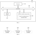
- the switching device 300 includes a processor 310 and a machine-readable storage medium 320, where the processor 310 and the machine-readable storage medium 320 may be connected with each other via an internal bus 330.
- the switching device 300 may further include an external interface 340 for communicating with other device or component.
- the machine-readable storage medium 320 may be: a Random Access Memory (RAM), a volatile memory, a nonvolatile memory, a flash memory, a memory drive (e.g. a hard disk drive), a solid-state hard disk, any type of storage disks (e.g. a compact disk, a DVD or the like), or a similar storage medium, or a combination thereof.
- RAM Random Access Memory
- volatile memory e.g. a volatile memory
- nonvolatile memory e.g. a nonvolatile memory
- a flash memory e.g. a solid-state hard disk, any type of storage disks (e.g. a compact disk, a DVD or the like), or a similar storage medium, or a combination thereof.
- a memory drive e.g. a hard disk drive
- solid-state hard disk e.g. a solid-state hard disk
- any type of storage disks e.g. a compact disk, a DVD or the like
- similar storage medium
- machine-executable instructions corresponding to a logic 400 for switching between operation modes are stored on the machine-readable storage medium 320.
- the logic 400 for switching between the operation modes may functionally include the following modules:
- the operation mode may include a black/white mode and a color mode.
- the detecting module 420 is configured to perform the following operations when whether to switch operation modes is determined according to the current operation mode and the amount of ambient illumination:
- the detecting module 420 is configured to perform the following operations when whether to switch operation modes is determined according to the distance between the monitored target and the video surveillance device:
- the switching module 430 is configured to perform the following operations:
- the switching module 430 is further configured to perform the following operations:
- the switching device 300 executes the logic 400 for switching between operation modes is further described below by taking implementation of software as an example.
- the logic 400 for switching between operation modes in the present disclosure may be understood as machine-executable instructions stored on the machine-readable storage medium 320.
- the processor 310 of the switching device 300 disclosed herein may execute the following operations by invoking the machine-executable instructions corresponding to the logic 400 for switching between operation modes and stored on the machine-readable storage medium 320:
- the operation mode may include a black/white mode and a color mode.
- the machine-executable instructions may also cause the processor to: determine whether to switch between operation modes according to the current operation mode and the amount of ambient illumination.
- the machine-executable instructions may cause the processor to:
- the machine-executable instructions may also cause the processor to: determine whether to switch between operation modes according to the distance between the monitored target and the video surveillance device.
- the machine-executable instructions may cause the processor to:
- the machine-executable instructions may cause the processor to:
- the machine-executable instructions may also cause the processor to:
Landscapes
- Engineering & Computer Science (AREA)
- Multimedia (AREA)
- Signal Processing (AREA)
- Studio Devices (AREA)
- Exposure Control For Cameras (AREA)
- Blocking Light For Cameras (AREA)
Claims (7)
- Verfahren zur Umschaltung zwischen Betriebsmodi einer Videoüberwachungsvorrichtung, umfassend:Lesen eines aktuellen Betriebsmodus der Videoüberwachungsvorrichtung und Aufzeichnen eines Belichtungsparameters des aktuellen Betriebsmodus (S1); undBestimmen, ob eine Umschaltung zwischen Betriebsmodi, die einen Schwarz/Weiß-Modus und einen Farbmodus umfassen, durchgeführt werden soll (S2), in Abhängigkeit von dem aktuellen Betriebsmodus und einem Maß an Umgebungsbeleuchtung;falls die Umschaltung zwischen den Betriebsmodi durchgeführt werden soll (S2),ist das Verfahren ferner gekennzeichnet durchEinstellen eines Zielbelichtungswerts eines Zielbetriebsmodus, auf den umgeschaltet werden soll, undBerechnen eines Belichtungsparameters des Zielbetriebsmodus entsprechend dem Zielbelichtungswert in Kombination mit dem Belichtungsparameter des aktuellen Betriebsmodus (S3), undAnpassen der Videoüberwachungsvorrichtung anhand des berechneten Belichtungsparameters;wobei das Bestimmen, ob die Umschaltung zwischen den Betriebsmodi durchgeführt werden soll (S2) in Abhängigkeit von dem aktuellen Betriebsmodus und dem Maß an Umgebungsbeleuchtung Folgendes umfasst:falls der aktuelle Betriebsmodus der Schwarz/Weiß-Modus ist, Bestimmen, dass der aktuelle Betriebsmodus auf den Farbmodus umgeschaltet werden soll, wenn das Maß an Umgebungsbeleuchtung über einem bestimmten Schwellenwert liegt; undfalls der aktuelle Betriebsmodus der Farbmodus ist, Bestimmen, dass der aktuelle Betriebsmodus auf den Schwarz/Weiß-Modus umgeschaltet werden soll, wenn das Maß an Umgebungsbeleuchtung unter einem bestimmten Schwellenwert liegt.
- Verfahren zur Umschaltung zwischen Betriebsmodi einer Videoüberwachungsvorrichtung, umfassend:Lesen eines aktuellen Betriebsmodus der Videoüberwachungsvorrichtung und Aufzeichnen eines Belichtungsparameters des aktuellen Betriebsmodus (S1); und gekennzeichnet durch das Bestimmen, ob eine Umschaltung zwischen Betriebsmodi, die einen Schwarz/Weiß-Modus und einen Farbmodus umfassen, durchgeführt werden soll (S2), in Abhängigkeit von dem aktuellen Betriebsmodus und einem Abstand zwischen einem überwachten Ziel und der Videoüberwachungsvorrichtung,falls die Umschaltung zwischen den Betriebsmodi durchgeführt werden soll (S2),Einstellen eines Zielbelichtungswerts eines Zielbetriebsmodus, auf den umgeschaltet werden soll, undBerechnen eines Belichtungsparameters des Zielbetriebsmodus entsprechend dem Zielbelichtungswert in Kombination mit dem Belichtungsparameter des aktuellen Betriebsmodus (S3), undAnpassen der Videoüberwachungsvorrichtung anhand des berechneten Belichtungsparameters;wobei das Bestimmen, ob die Umschaltung zwischen den Betriebsmodi durchgeführt werden soll (S2) in Abhängigkeit von dem Abstand zwischen einem überwachten Ziel und der Videoüberwachungsvorrichtung umfasst:Erfassen des Abstands zwischen dem überwachten Ziel und der Videoüberwachungsvorrichtung durch eine Bewegungserkennung oder eine Passiv-Infrarot (PIR)-Erkennung; undBestimmen, dass der aktuelle Betriebsmodus auf den Farbmodus umgeschaltet werden soll, wenn der erfasste Abstand innerhalb eines bestimmten Bereichs liegt.
- Verfahren nach Anspruch 1 oder 2, wobei das Einstellen des Zielbelichtungswerts des Zielbetriebsmodus, auf den umgeschaltet werden soll, und das Berechnen des Belichtungsparameters des Zielbetriebsmodus entsprechend dem Zielbelichtungswert in Kombination mit dem Belichtungsparameter des aktuellen Betriebsmodus (S3) umfassen:Berechnen des Belichtungsparameters des Zielbetriebsmodus gemäß der folgenden Formel:
 wobei T2 der Belichtungswert des aktuellen Betriebsmodus ist,G2 eine Verstärkung des aktuellen Betriebsmodus ist,S2 eine Verschlussgeschwindigkeit des aktuellen Betriebsmodus ist,R2 eine Blende des aktuellen Betriebsmodus ist,P2 die Leistung eines Weißlichtkompensators im aktuellen Betriebsmodus ist,K2 ein Transmissionsgrad eines Lichtfilters im aktuellen Betriebsmodus ist,T1 ein Zielbelichtungswert des Zielbetriebsmodus ist,G1 eine Verstärkung des Zielbetriebsmodus ist,S1 eine Verschlussgeschwindigkeit des Zielbetriebsmodus ist,R1 eine Blende des Zielbetriebsmodus ist,P1 die Leistung des Weißlichtkompensators im Zielbetriebsmodus ist, undK1 ein Transmissionsgrad des Lichtfilters im Zielbetriebsmodus ist.
 - Verfahren nach Anspruch 3, ferner umfassend:Einstellen der Verschlussgeschwindigkeit S1 des Zielbetriebsmodus auf eins in einer Bildrate der Videoüberwachungsvorrichtung, undAnpassen der Verstärkung der Videoüberwachungsvorrichtung entsprechend der berechneten Verstärkung G1 des Zielbetriebsmodus.
- Videoüberwachungsvorrichtung (300), umfassend:einen Prozessor (310); undein maschinenlesbares Speichermedium, das maschinenausführbare Anweisungen speichert, die einer Logik zum Umschalten zwischen Betriebsmodi (400) entsprechen,wobei der Prozessor (310) durch Lesen und Ausführen der maschinenausführbaren Anweisungen den folgenden Vorgang ausführt:Lesen eines aktuellen Betriebsmodus der Videoüberwachungsvorrichtung und Aufzeichnen eines Belichtungsparameters des aktuellen Betriebsmodus; undBestimmen, ob eine Umschaltung zwischen Betriebsmodi, die einen Schwarz/Weiß-Modus und einen Farbmodus umfassen, durchgeführt werden soll (S2), in Abhängigkeit von dem aktuellen Betriebsmodus und einem Maß an Umgebungsbeleuchtung;falls die Umschaltung zwischen den Betriebsmodi durchgeführt werden soll (S2),ferner gekennzeichnet durchEinstellen eines Zielbelichtungswerts eines Zielbetriebsmodus, auf den umgeschaltet werden soll, undBerechnen eines Belichtungsparameters des Zielbetriebsmodus entsprechend dem Zielbelichtungswert in Kombination mit dem Belichtungsparameter des aktuellen Betriebsmodus, undAnpassen der Videoüberwachungsvorrichtung anhand des berechneten Belichtungsparameters;wobei das Bestimmen, ob die Umschaltung zwischen den Betriebsmodi durchgeführt werden soll in Abhängigkeit von dem aktuellen Betriebsmodus und dem Maß an Umgebungsbeleuchtung Folgendes umfasst:falls der aktuelle Betriebsmodus der Schwarz/Weiß-Modus ist, Bestimmen, dass der aktuelle Betriebsmodus auf den Farbmodus umgeschaltet werden soll, wenn das Maß an Umgebungsbeleuchtung über einem bestimmten Schwellenwert liegt; undfalls der aktuelle Betriebsmodus der Farbmodus ist, Bestimmen, dass der aktuelle Betriebsmodus auf den Schwarz/Weiß-Modus umgeschaltet werden soll, wenn das Maß an Umgebungsbeleuchtung unter einem bestimmten Schwellenwert liegt.
- Videoüberwachungsvorrichtung (300), umfassend:einen Prozessor (310); undein maschinenlesbares Speichermedium, das maschinenausführbare Anweisungen speichert, die einer Logik zum Umschalten zwischen Betriebsmodi (400) entsprechen,wobei der Prozessor (310) durch Lesen und Ausführen der maschinenausführbaren Anweisungen den folgenden Vorgang ausführt:Lesen eines aktuellen Betriebsmodus der Videoüberwachungsvorrichtung und Aufzeichnen eines Belichtungsparameters des aktuellen Betriebsmodus (S1); und gekennzeichnet durchBestimmen, ob eine Umschaltung zwischen Betriebsmodi, die einen Schwarz/Weiß-Modus und einen Farbmodus umfassen, durchgeführt werden soll (S2) in Abhängigkeit von dem aktuellen Betriebsmodus und einem Abstand zwischen einem überwachten Ziel und der Videoüberwachungsvorrichtung,falls die Umschaltung zwischen den Betriebsmodi durchgeführt werden soll (S2),Einstellen eines Zielbelichtungswerts eines Zielbetriebsmodus, auf den umgeschaltet werden soll, undBerechnen eines Belichtungsparameters des Zielbetriebsmodus entsprechend dem Zielbelichtungswert in Kombination mit dem Belichtungsparameter des aktuellen Betriebsmodus (S3), undAnpassen der Videoüberwachungsvorrichtung anhand des berechneten Belichtungsparameters;wobei das Bestimmen, ob die Umschaltung zwischen den Betriebsmodi durchgeführt werden soll (S2) in Abhängigkeit von dem Abstand zwischen einem überwachten Ziel und der Videoüberwachungsvorrichtung umfasst:Erfassen des Abstands zwischen dem überwachten Ziel und der Videoüberwachungsvorrichtung durch eine Bewegungserkennung oder eine Passiv-Infrarot (PIR)-Erkennung; undBestimmen, dass der aktuelle Betriebsmodus auf den Farbmodus umgeschaltet werden soll, wenn der erfasste Abstand innerhalb eines bestimmten Bereichs liegt.
- Vorrichtung (300) nach Anspruch 5 oder 6, wobei, wenn der Zielbelichtungswert des Zielbetriebsmodus, auf den umgeschaltet werden soll, eingestellt wird, und der Belichtungsparameter des Zielbetriebsmodus entsprechend dem Zielbelichtungswert in Kombination mit dem Belichtungsparameter des aktuellen Betriebsmodus berechnet wird, der Prozessor (310) durch die maschinenausführbaren Anweisungen veranlasst wird zum:Berechnen des Belichtungsparameters des Zielbetriebsmodus gemäß der folgenden Formel:
 wobei T2 der Belichtungswert des aktuellen Betriebsmodus ist,G2 eine Verstärkung des aktuellen Betriebsmodus ist,S2 eine Verschlussgeschwindigkeit des aktuellen Betriebsmodus ist,R2 eine Blende des aktuellen Betriebsmodus ist,P2 die Leistung eines Weißlichtkompensators im aktuellen Betriebsmodus ist,K2 ein Transmissionsgrad eines Lichtfilters im aktuellen Betriebsmodus ist,T1 ein Zielbelichtungswert des Zielbetriebsmodus ist,G1 eine Verstärkung des Zielbetriebsmodus ist,S1 eine Verschlussgeschwindigkeit des Zielbetriebsmodus ist,R1 eine Blende des Zielbetriebsmodus ist,P1 die Leistung des Weißlichtkompensators im Zielbetriebsmodus ist, undK1 ein Transmissionsgrad des Lichtfilters im Zielbetriebsmodus ist.
Applications Claiming Priority (2)
| Application Number | Priority Date | Filing Date | Title |
|---|---|---|---|
| CN201510881516.6A CN105491285B (zh) | 2015-12-03 | 2015-12-03 | 一种pir摄像机工作模式切换方法及装置 |
| PCT/CN2016/097409 WO2017092445A1 (zh) | 2015-12-03 | 2016-08-30 | 视频监控设备的工作模式的切换 |
Publications (4)
| Publication Number | Publication Date |
|---|---|
| EP3358823A1 EP3358823A1 (de) | 2018-08-08 |
| EP3358823A4 EP3358823A4 (de) | 2018-11-07 |
| EP3358823C0 EP3358823C0 (de) | 2023-08-16 |
| EP3358823B1 true EP3358823B1 (de) | 2023-08-16 |
Family
ID=55677971
Family Applications (1)
| Application Number | Title | Priority Date | Filing Date |
|---|---|---|---|
| EP16869756.3A Active EP3358823B1 (de) | 2015-12-03 | 2016-08-30 | Verfahren und vorrichtung zur umschaltung zwischen betriebsmodi einer videoüberwachungsvorrichtung |
Country Status (7)
| Country | Link |
|---|---|
| US (1) | US10630900B2 (de) |
| EP (1) | EP3358823B1 (de) |
| CN (1) | CN105491285B (de) |
| ES (1) | ES2963066T3 (de) |
| HU (1) | HUE063652T2 (de) |
| PL (1) | PL3358823T3 (de) |
| WO (1) | WO2017092445A1 (de) |
Families Citing this family (9)
| Publication number | Priority date | Publication date | Assignee | Title |
|---|---|---|---|---|
| CN105491285B (zh) | 2015-12-03 | 2019-02-15 | 浙江宇视科技有限公司 | 一种pir摄像机工作模式切换方法及装置 |
| US11284012B2 (en) | 2017-07-03 | 2022-03-22 | Canon Kabushiki Kaisha | Method and system for auto-setting of cameras |
| JP2019129446A (ja) * | 2018-01-25 | 2019-08-01 | ソニーセミコンダクタソリューションズ株式会社 | 画像処理装置、および画像処理方法、並びにプログラム |
| CN110557571B (zh) * | 2018-05-31 | 2020-10-13 | 杭州海康威视数字技术股份有限公司 | 一种图像采集设备、设备控制方法、装置及存储介质 |
| CN111064899B (zh) * | 2019-12-06 | 2021-06-08 | 成都华为技术有限公司 | 一种曝光参数的调节方法及装置 |
| CN111770286B (zh) * | 2020-08-04 | 2023-04-07 | 深圳市恩港科技开发有限公司 | 电子警察抓拍方法、电子设备和存储介质 |
| CN114125293B (zh) * | 2021-11-19 | 2024-02-23 | 浙江宇视科技有限公司 | 一种双光摄像机的图像质量控制方法、装置、介质及设备 |
| CN116033275B (zh) * | 2023-03-29 | 2023-08-15 | 荣耀终端有限公司 | 一种自动曝光方法、电子设备及计算机可读存储介质 |
| EP4557720A1 (de) * | 2023-11-17 | 2025-05-21 | Axis AB | Verfahren zur steuerung einer kamera zur überwachung einer szene |
Family Cites Families (17)
| Publication number | Priority date | Publication date | Assignee | Title |
|---|---|---|---|---|
| US7071971B2 (en) * | 1997-08-25 | 2006-07-04 | Elbex Video Ltd. | Apparatus for identifying the scene location viewed via remotely operated television camera |
| JP3468231B2 (ja) | 2001-07-02 | 2003-11-17 | ミノルタ株式会社 | 画像処理装置、画質制御方法、プログラム及び記録媒体 |
| JP2003134520A (ja) * | 2001-10-19 | 2003-05-09 | Minolta Co Ltd | デジタルカメラ |
| US20030093805A1 (en) * | 2001-11-15 | 2003-05-15 | Gin J.M. Jack | Dual camera surveillance and control system |
| WO2004047421A2 (en) * | 2002-11-14 | 2004-06-03 | Donnelly Corporation | Imaging system for vehicle |
| KR100573697B1 (ko) * | 2003-12-29 | 2006-04-26 | 삼성전자주식회사 | 광학기기의 광학필터 절환 장치 |
| JP4290022B2 (ja) | 2004-01-23 | 2009-07-01 | キヤノン株式会社 | 撮像装置及び画像調整方法 |
| CN201127061Y (zh) * | 2007-12-19 | 2008-10-01 | 深圳市同洲电子股份有限公司 | 摄像装置及低照度条件下的影像处理设备 |
| JP5148989B2 (ja) * | 2007-12-27 | 2013-02-20 | イーストマン コダック カンパニー | 撮像装置 |
| US8264437B2 (en) * | 2008-08-29 | 2012-09-11 | Sony Mobile Communications Ab | Display for high brightness conditions |
| US8305447B1 (en) * | 2009-08-27 | 2012-11-06 | Wong Thomas K | Security threat detection system |
| CN101893804B (zh) * | 2010-05-13 | 2012-02-29 | 杭州海康威视软件有限公司 | 曝光控制方法及装置 |
| CN102724404B (zh) * | 2012-06-08 | 2014-06-25 | 北京大恒图像视觉有限公司 | 一种全天候曝光增益自动调节方法和系统 |
| CN103533252B (zh) * | 2013-09-30 | 2017-02-22 | 浙江宇视科技有限公司 | 一种昼夜模式自动切换的方法和装置 |
| CN103702038B (zh) | 2013-12-31 | 2017-04-19 | 浙江宇视科技有限公司 | 一种基于动态阈值进行自动昼夜切换的方法和装置 |
| US9813630B1 (en) * | 2015-06-08 | 2017-11-07 | Ambarella, Inc. | Picture brightness adjusted motion detection |
| CN105491285B (zh) | 2015-12-03 | 2019-02-15 | 浙江宇视科技有限公司 | 一种pir摄像机工作模式切换方法及装置 |
-
2015
- 2015-12-03 CN CN201510881516.6A patent/CN105491285B/zh active Active
-
2016
- 2016-08-30 HU HUE16869756A patent/HUE063652T2/hu unknown
- 2016-08-30 EP EP16869756.3A patent/EP3358823B1/de active Active
- 2016-08-30 PL PL16869756.3T patent/PL3358823T3/pl unknown
- 2016-08-30 US US15/774,974 patent/US10630900B2/en active Active
- 2016-08-30 WO PCT/CN2016/097409 patent/WO2017092445A1/zh not_active Ceased
- 2016-08-30 ES ES16869756T patent/ES2963066T3/es active Active
Also Published As
| Publication number | Publication date |
|---|---|
| ES2963066T3 (es) | 2024-03-25 |
| PL3358823T3 (pl) | 2024-03-18 |
| US10630900B2 (en) | 2020-04-21 |
| US20180376063A1 (en) | 2018-12-27 |
| EP3358823A1 (de) | 2018-08-08 |
| EP3358823C0 (de) | 2023-08-16 |
| HUE063652T2 (hu) | 2024-01-28 |
| CN105491285A (zh) | 2016-04-13 |
| WO2017092445A1 (zh) | 2017-06-08 |
| CN105491285B (zh) | 2019-02-15 |
| EP3358823A4 (de) | 2018-11-07 |
Similar Documents
| Publication | Publication Date | Title |
|---|---|---|
| EP3358823B1 (de) | Verfahren und vorrichtung zur umschaltung zwischen betriebsmodi einer videoüberwachungsvorrichtung | |
| TWI419552B (zh) | 攝影裝置、被攝體追蹤方法及記錄媒體 | |
| US9967454B2 (en) | Digital image photographing apparatus and method of controlling the same | |
| CN101247471B (zh) | 运动检测设备、运动检测方法、成像设备和监视系统 | |
| US20110081141A1 (en) | Focus adjusting device, image pickup apparatus, and focus adjustment method | |
| CN104205797B (zh) | 摄像装置 | |
| US20130293766A1 (en) | Imaging device and main photographic subject recognition method | |
| US20120133730A1 (en) | Image pickup apparatus that automatically determines shooting mode most suitable for shooting scene, control method therefor, and storage medium | |
| CN103763458A (zh) | 一种场景变化检测方法及装置 | |
| US7746403B2 (en) | Image capturing apparatus having a plurality of focus detention devices and control method therefor | |
| CN102509452B (zh) | 智能交通监测系统的闪光灯控制方法及其装置 | |
| US9118907B2 (en) | Imaging device enabling automatic taking of photo when pre-registered object moves into photographer's intended shooting distance | |
| US20110211038A1 (en) | Image composing apparatus | |
| JP5910852B2 (ja) | 動作制御装置および動作制御方法、撮像装置、並びにプログラム | |
| KR20230131910A (ko) | 촬영 방법, 촬영 장치 및 전자 장치 | |
| JP2015111226A (ja) | 被写体追跡装置及びその制御方法、撮像装置、プログラム、並びに記憶媒体 | |
| KR20120008806A (ko) | 카메라 모듈 및 이를 포함한 이동통신 단말기 | |
| JP4006213B2 (ja) | 撮像装置及びその合焦制御方法、並びにプログラム | |
| JP2004341095A (ja) | オートフォーカスカメラ | |
| US10321041B2 (en) | Imaging apparatus, control method of imaging apparatus, and non-transitory storage medium storing control method of imaging apparatus | |
| JP4957461B2 (ja) | 撮像装置及び撮像方法 | |
| JP5854861B2 (ja) | 撮像装置、その制御方法、および制御プログラム | |
| JP5069076B2 (ja) | 撮像装置および連続撮像方法 | |
| JP4769667B2 (ja) | 撮像装置 | |
| US20240144493A1 (en) | Information processing apparatus, information processing system, information processing method, and storage medium |
Legal Events
| Date | Code | Title | Description |
|---|---|---|---|
| STAA | Information on the status of an ep patent application or granted ep patent |
Free format text: STATUS: THE INTERNATIONAL PUBLICATION HAS BEEN MADE |
|
| PUAI | Public reference made under article 153(3) epc to a published international application that has entered the european phase |
Free format text: ORIGINAL CODE: 0009012 |
|
| STAA | Information on the status of an ep patent application or granted ep patent |
Free format text: STATUS: REQUEST FOR EXAMINATION WAS MADE |
|
| 17P | Request for examination filed |
Effective date: 20180503 |
|
| AK | Designated contracting states |
Kind code of ref document: A1 Designated state(s): AL AT BE BG CH CY CZ DE DK EE ES FI FR GB GR HR HU IE IS IT LI LT LU LV MC MK MT NL NO PL PT RO RS SE SI SK SM TR |
|
| AX | Request for extension of the european patent |
Extension state: BA ME |
|
| RIC1 | Information provided on ipc code assigned before grant |
Ipc: H04N 5/235 20060101ALI20180927BHEP Ipc: H04N 5/232 20060101AFI20180927BHEP |
|
| A4 | Supplementary search report drawn up and despatched |
Effective date: 20181005 |
|
| DAV | Request for validation of the european patent (deleted) | ||
| DAX | Request for extension of the european patent (deleted) | ||
| STAA | Information on the status of an ep patent application or granted ep patent |
Free format text: STATUS: EXAMINATION IS IN PROGRESS |
|
| 17Q | First examination report despatched |
Effective date: 20210209 |
|
| REG | Reference to a national code |
Ref country code: DE Ref legal event code: R079 Ipc: H04N0023667000 Ref country code: DE Ref legal event code: R079 Ref document number: 602016082027 Country of ref document: DE Free format text: PREVIOUS MAIN CLASS: H04N0005232000 Ipc: H04N0023667000 |
|
| GRAP | Despatch of communication of intention to grant a patent |
Free format text: ORIGINAL CODE: EPIDOSNIGR1 |
|
| STAA | Information on the status of an ep patent application or granted ep patent |
Free format text: STATUS: GRANT OF PATENT IS INTENDED |
|
| RIC1 | Information provided on ipc code assigned before grant |
Ipc: H04N 23/72 20230101ALI20230223BHEP Ipc: H04N 23/667 20230101AFI20230223BHEP |
|
| INTG | Intention to grant announced |
Effective date: 20230329 |
|
| GRAS | Grant fee paid |
Free format text: ORIGINAL CODE: EPIDOSNIGR3 |
|
| GRAA | (expected) grant |
Free format text: ORIGINAL CODE: 0009210 |
|
| STAA | Information on the status of an ep patent application or granted ep patent |
Free format text: STATUS: THE PATENT HAS BEEN GRANTED |
|
| AK | Designated contracting states |
Kind code of ref document: B1 Designated state(s): AL AT BE BG CH CY CZ DE DK EE ES FI FR GB GR HR HU IE IS IT LI LT LU LV MC MK MT NL NO PL PT RO RS SE SI SK SM TR |
|
| REG | Reference to a national code |
Ref country code: GB Ref legal event code: FG4D |
|
| REG | Reference to a national code |
Ref country code: CH Ref legal event code: EP Ref country code: DE Ref legal event code: R096 Ref document number: 602016082027 Country of ref document: DE |
|
| REG | Reference to a national code |
Ref country code: IE Ref legal event code: FG4D |
|
| U01 | Request for unitary effect filed |
Effective date: 20230823 |
|
| U07 | Unitary effect registered |
Designated state(s): AT BE BG DE DK EE FI FR IT LT LU LV MT NL PT SE SI Effective date: 20230830 |
|
| U20 | Renewal fee for the european patent with unitary effect paid |
Year of fee payment: 8 Effective date: 20231019 |
|
| PG25 | Lapsed in a contracting state [announced via postgrant information from national office to epo] |
Ref country code: GR Free format text: LAPSE BECAUSE OF FAILURE TO SUBMIT A TRANSLATION OF THE DESCRIPTION OR TO PAY THE FEE WITHIN THE PRESCRIBED TIME-LIMIT Effective date: 20231117 |
|
| PG25 | Lapsed in a contracting state [announced via postgrant information from national office to epo] |
Ref country code: IS Free format text: LAPSE BECAUSE OF FAILURE TO SUBMIT A TRANSLATION OF THE DESCRIPTION OR TO PAY THE FEE WITHIN THE PRESCRIBED TIME-LIMIT Effective date: 20231216 |
|
| REG | Reference to a national code |
Ref country code: HU Ref legal event code: AG4A Ref document number: E063652 Country of ref document: HU |
|
| PG25 | Lapsed in a contracting state [announced via postgrant information from national office to epo] |
Ref country code: RS Free format text: LAPSE BECAUSE OF FAILURE TO SUBMIT A TRANSLATION OF THE DESCRIPTION OR TO PAY THE FEE WITHIN THE PRESCRIBED TIME-LIMIT Effective date: 20230816 Ref country code: NO Free format text: LAPSE BECAUSE OF FAILURE TO SUBMIT A TRANSLATION OF THE DESCRIPTION OR TO PAY THE FEE WITHIN THE PRESCRIBED TIME-LIMIT Effective date: 20231116 Ref country code: IS Free format text: LAPSE BECAUSE OF FAILURE TO SUBMIT A TRANSLATION OF THE DESCRIPTION OR TO PAY THE FEE WITHIN THE PRESCRIBED TIME-LIMIT Effective date: 20231216 Ref country code: HR Free format text: LAPSE BECAUSE OF FAILURE TO SUBMIT A TRANSLATION OF THE DESCRIPTION OR TO PAY THE FEE WITHIN THE PRESCRIBED TIME-LIMIT Effective date: 20230816 Ref country code: GR Free format text: LAPSE BECAUSE OF FAILURE TO SUBMIT A TRANSLATION OF THE DESCRIPTION OR TO PAY THE FEE WITHIN THE PRESCRIBED TIME-LIMIT Effective date: 20231117 |
|
| REG | Reference to a national code |
Ref country code: ES Ref legal event code: FG2A Ref document number: 2963066 Country of ref document: ES Kind code of ref document: T3 Effective date: 20240325 |
|
| REG | Reference to a national code |
Ref country code: CH Ref legal event code: PL |
|
| PG25 | Lapsed in a contracting state [announced via postgrant information from national office to epo] |
Ref country code: SM Free format text: LAPSE BECAUSE OF FAILURE TO SUBMIT A TRANSLATION OF THE DESCRIPTION OR TO PAY THE FEE WITHIN THE PRESCRIBED TIME-LIMIT Effective date: 20230816 Ref country code: RO Free format text: LAPSE BECAUSE OF FAILURE TO SUBMIT A TRANSLATION OF THE DESCRIPTION OR TO PAY THE FEE WITHIN THE PRESCRIBED TIME-LIMIT Effective date: 20230816 Ref country code: CZ Free format text: LAPSE BECAUSE OF FAILURE TO SUBMIT A TRANSLATION OF THE DESCRIPTION OR TO PAY THE FEE WITHIN THE PRESCRIBED TIME-LIMIT Effective date: 20230816 Ref country code: CH Free format text: LAPSE BECAUSE OF NON-PAYMENT OF DUE FEES Effective date: 20230831 Ref country code: SK Free format text: LAPSE BECAUSE OF FAILURE TO SUBMIT A TRANSLATION OF THE DESCRIPTION OR TO PAY THE FEE WITHIN THE PRESCRIBED TIME-LIMIT Effective date: 20230816 |
|
| REG | Reference to a national code |
Ref country code: DE Ref legal event code: R097 Ref document number: 602016082027 Country of ref document: DE |
|
| REG | Reference to a national code |
Ref country code: IE Ref legal event code: MM4A |
|
| PG25 | Lapsed in a contracting state [announced via postgrant information from national office to epo] |
Ref country code: MC Free format text: LAPSE BECAUSE OF FAILURE TO SUBMIT A TRANSLATION OF THE DESCRIPTION OR TO PAY THE FEE WITHIN THE PRESCRIBED TIME-LIMIT Effective date: 20230816 |
|
| PLBE | No opposition filed within time limit |
Free format text: ORIGINAL CODE: 0009261 |
|
| STAA | Information on the status of an ep patent application or granted ep patent |
Free format text: STATUS: NO OPPOSITION FILED WITHIN TIME LIMIT |
|
| PG25 | Lapsed in a contracting state [announced via postgrant information from national office to epo] |
Ref country code: IE Free format text: LAPSE BECAUSE OF NON-PAYMENT OF DUE FEES Effective date: 20230830 |
|
| 26N | No opposition filed |
Effective date: 20240517 |
|
| PG25 | Lapsed in a contracting state [announced via postgrant information from national office to epo] |
Ref country code: IE Free format text: LAPSE BECAUSE OF NON-PAYMENT OF DUE FEES Effective date: 20230830 |
|
| U20 | Renewal fee for the european patent with unitary effect paid |
Year of fee payment: 9 Effective date: 20240807 |
|
| PG25 | Lapsed in a contracting state [announced via postgrant information from national office to epo] |
Ref country code: CY Free format text: LAPSE BECAUSE OF FAILURE TO SUBMIT A TRANSLATION OF THE DESCRIPTION OR TO PAY THE FEE WITHIN THE PRESCRIBED TIME-LIMIT; INVALID AB INITIO Effective date: 20160830 |
|
| PGFP | Annual fee paid to national office [announced via postgrant information from national office to epo] |
Ref country code: HU Payment date: 20250825 Year of fee payment: 10 |
|
| U20 | Renewal fee for the european patent with unitary effect paid |
Year of fee payment: 10 Effective date: 20250827 |
|
| PGFP | Annual fee paid to national office [announced via postgrant information from national office to epo] |
Ref country code: ES Payment date: 20250926 Year of fee payment: 10 |
|
| PGFP | Annual fee paid to national office [announced via postgrant information from national office to epo] |
Ref country code: PL Payment date: 20250821 Year of fee payment: 10 Ref country code: TR Payment date: 20250825 Year of fee payment: 10 |
|
| PGFP | Annual fee paid to national office [announced via postgrant information from national office to epo] |
Ref country code: GB Payment date: 20250821 Year of fee payment: 10 |