EP3358591B1 - Hilfsrelais eines elektromagnetischen schützes - Google Patents
Hilfsrelais eines elektromagnetischen schützes Download PDFInfo
- Publication number
- EP3358591B1 EP3358591B1 EP17163724.2A EP17163724A EP3358591B1 EP 3358591 B1 EP3358591 B1 EP 3358591B1 EP 17163724 A EP17163724 A EP 17163724A EP 3358591 B1 EP3358591 B1 EP 3358591B1
- Authority
- EP
- European Patent Office
- Prior art keywords
- switch portion
- conductive member
- magnet
- turned
- brought
- Prior art date
- Legal status (The legal status is an assumption and is not a legal conclusion. Google has not performed a legal analysis and makes no representation as to the accuracy of the status listed.)
- Active
Links
Images




Classifications
-
- H—ELECTRICITY
- H01—ELECTRIC ELEMENTS
- H01H—ELECTRIC SWITCHES; RELAYS; SELECTORS; EMERGENCY PROTECTIVE DEVICES
- H01H50/00—Details of electromagnetic relays
- H01H50/64—Driving arrangements between movable part of magnetic circuit and contact
- H01H50/74—Mechanical means for producing a desired natural frequency of operation of the contacts, e.g. for self-interrupter
- H01H50/76—Mechanical means for producing a desired natural frequency of operation of the contacts, e.g. for self-interrupter using reed or blade spring
-
- H—ELECTRICITY
- H01—ELECTRIC ELEMENTS
- H01H—ELECTRIC SWITCHES; RELAYS; SELECTORS; EMERGENCY PROTECTIVE DEVICES
- H01H50/00—Details of electromagnetic relays
- H01H50/54—Contact arrangements
- H01H50/541—Auxiliary contact devices
-
- H—ELECTRICITY
- H01—ELECTRIC ELEMENTS
- H01H—ELECTRIC SWITCHES; RELAYS; SELECTORS; EMERGENCY PROTECTIVE DEVICES
- H01H36/00—Switches actuated by change of magnetic field or of electric field, e.g. by change of relative position of magnet and switch, by shielding
- H01H36/0006—Permanent magnet actuating reed switches
-
- H—ELECTRICITY
- H01—ELECTRIC ELEMENTS
- H01H—ELECTRIC SWITCHES; RELAYS; SELECTORS; EMERGENCY PROTECTIVE DEVICES
- H01H50/00—Details of electromagnetic relays
- H01H50/02—Bases; Casings; Covers
-
- H—ELECTRICITY
- H01—ELECTRIC ELEMENTS
- H01H—ELECTRIC SWITCHES; RELAYS; SELECTORS; EMERGENCY PROTECTIVE DEVICES
- H01H50/00—Details of electromagnetic relays
- H01H50/02—Bases; Casings; Covers
- H01H50/04—Mounting complete relay or separate parts of relay on a base or inside a case
-
- H—ELECTRICITY
- H01—ELECTRIC ELEMENTS
- H01H—ELECTRIC SWITCHES; RELAYS; SELECTORS; EMERGENCY PROTECTIVE DEVICES
- H01H50/00—Details of electromagnetic relays
- H01H50/14—Terminal arrangements
-
- H—ELECTRICITY
- H01—ELECTRIC ELEMENTS
- H01H—ELECTRIC SWITCHES; RELAYS; SELECTORS; EMERGENCY PROTECTIVE DEVICES
- H01H51/00—Electromagnetic relays
- H01H51/28—Relays having both armature and contacts within a sealed casing outside which the operating coil is located, e.g. contact carried by a magnetic leaf spring or reed
- H01H51/282—Constructional details not covered by H01H51/281
-
- H—ELECTRICITY
- H01—ELECTRIC ELEMENTS
- H01H—ELECTRIC SWITCHES; RELAYS; SELECTORS; EMERGENCY PROTECTIVE DEVICES
- H01H36/00—Switches actuated by change of magnetic field or of electric field, e.g. by change of relative position of magnet and switch, by shielding
- H01H36/0006—Permanent magnet actuating reed switches
- H01H36/0013—Permanent magnet actuating reed switches characterised by the co-operation between reed switch and permanent magnet; Magnetic circuits
Definitions
- This specification relates to an auxiliary relay of an electromagnetic contactor, and more particularly, an auxiliary relay of an electromagnetic contactor, capable of improving current-applying efficiency by preventing an external exposure of a contact portion and variously adjusting a contact configuration.
- an electromagnetic contactor refers to a device that opens or closes a load in a transmission system, a substation or an electric circuit, or cuts off current when an accident such as a ground or short circuit occurs.
- the electromagnetic contactor is provided with an auxiliary relay on its top or side surface to assist an operation of a main contact.
- FIG. 1 illustrates an electromagnetic contactor having an auxiliary relay on a top thereof.
- an auxiliary relay 10 of the related art electromagnetic contactor is provided with an auxiliary fixed contact 13 on a frame 11, and an auxiliary movable contact 17 formed integrally with a moving member 15.
- the moving member 15 is connected to a crossbar (not illustrated) of the electromagnetic contactor to move up and down in conjunction with a vertical movement of the crossbar.
- the moving member 15 moves in response to the movement of the crossbar. Accordingly, the a-contact circuit is in the open state and the b-contact circuit is in the closed state.
- US5198789 A discloses an example of an auxiliary relay for an electromagnetic contactor according to the preamble claim 1.
- an aspect of the detailed description is to provide an electromagnetic contactor capable of improving conductivity by preventing an external exposure of a contact portion and variously adjusting a contact configuration.
- the first switch portion and the second switch portion provided on the first conductive member and the second conductive member may be located at positions corresponding to each other. Accordingly, the second switch portion may be turned on by being brought into close contact with the magnet member disposed on another side when the first switch portion is turned on by being brought into close contact with the magnet member disposed on one side, as the moving member moves. On the contrary, the second switch portion may be turned off by being brought into close contact with the magnet member disposed on another side when the first switch portion is turned off by being brought into close contact with the magnet member disposed on one side, as the moving member moves.
- the first switch portion and the second switch portion provided on the first conductive member and the second conductive member may be located at different positions from each other. Accordingly, the second switch portion may be turned off by being brought into close contact with the magnet member disposed on another side when the first switch portion is turned on by being brought into close contact with the magnet member disposed on one side, as the moving member moves. On the contrary, the second switch portion may be turned on by being brought into close contact with the magnet member disposed on another side when the first switch portion is turned off by being brought into close contact with the magnet member disposed on one side, as the moving member moves.
- the first switch portion and the second switch portion may be configured as reed switches.
- Each of the first conductive member and the second conductive member may be provided with a first terminal and a second terminal that are connected to the first switch portion or the second switch portion, such that a current is applied according to an ON or OFF state of the first switch portion and the second switch portion.
- the first terminal and the second terminal may be inclined by predetermined angles.
- Magnet member inserting portions in which the magnet members are fixedly inserted may be formed on both side surfaces of the moving member.
- Each of the magnet member inserting portions may have front and rear sides open.
- each of both sides of the frame may be provided guide portions in which the corresponding conductive member is inserted, and a hook portion located to be brought into contact with one end of the conductive member.
- Each of the conductive members may be provided with a blocking plate provided adjacent to the first switch portion or the second switch portion.
- Positions of reed switches provided in the first and second conductive members may be the same as or different from each other, so as to adjust states of the first and second conductive members by use of the magnet members, which may facilitate configuration of contact circuits of the electromagnetic contactor through a simple structure.
- Blocking plates provided on the first conductive member and the second conductive member prevent magnetic forces of the magnet members from affecting the switch portions when the magnet members are moved away from the switch portions, thereby preventing each of the switch portions from being maintained in an ON state without changing to an OFF state.
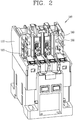
- FIG. 2 is a perspective view of an electromagnetic contactor provided with an auxiliary relay in accordance with one embodiment of the present invention
- FIG. 3 is a perspective view of a moving member provided in an auxiliary relay in accordance with one embodiment of the present invention
- FIG. 4 is a perspective view illustrating a removed state of a magnet member from a moving member provided in an auxiliary relay in accordance with one embodiment of the present invention
- FIG. 5A is a perspective view of a first conductive member constructing an auxiliary relay in accordance with one embodiment of the present invention
- FIG. 5B is a perspective view of a first conductive member constructing an auxiliary relay in accordance with another embodiment of the present invention.
- FIG. 6 is an internal configuration view illustrating a state that a first conductive member and a second conductive member are employed in an auxiliary relay to configure a 2a contact circuit in an OFF state of an electromagnetic contactor according to one embodiment
- FIG. 7 is an internal configuration view illustrating a state that a first conductive member and a second conductive member are employed in an auxiliary relay to configure a 2a contact circuit in an OFF state of an electromagnetic contactor according to one embodiment of the present invention
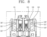
- FIG. 8 is an internal configuration view illustrating a state that a first conductive member and a second conductive member are employed in an auxiliary relay to configure a 2b contact circuit in an OFF state of an electromagnetic contactor according to one embodiment of the present invention
- FIG. 9 is a perspective view illustrating a state that a conductive member constructing an electromagnetic contactor according to the present invention is inserted in an auxiliary relay.
- an auxiliary relay 100 provided in an electromagnetic contactor includes a frame 110, a moving member 140, a first conductive member 120 and a second conductive member 130.
- the frame 110 defines appearance of the auxiliary relay 100, and is provided with various components constructing the auxiliary relay 100.
- the moving member 140 is provided within the frame 110 and connected to a crossbar (not illustrated) which is constructs a main contact of the electromagnetic contactor. In this connected state, the moving member 140 moves up and down in response to a movement of the crossbar.
- magnet member inserting portions 145 each of which has front and rear portions open are provided on both sides of the moving member 140. Magnet members 141 and 143 are inserted into the magnet member inserting portions 145 to be movable in response to the movement of the moving member 140, thereby controlling an ON or OFF state of the first conductive member 120 and the second conductive member 130.
- the first conductive member 120 is provided on one side of the frame 110 to be adjacent to the magnet member 141 within the frame 110.
- the first conductive member 120 is turned on or off by being closely adhered on the magnet member 141 or moved away from the magnet member 141 in response to the movement of the moving member 140.
- the first conductive member 120 is provided with a first switch portion 121 configured as a reed switch or the like.
- the magnet member 141 is closely adhered on or moved away from the first switch portion 121, thereby switching on or off the first conductive member 120.
- the reed switch is configured such that contact portions of magnetic material reeds are located in a glass tube filled with an inert gas.
- contact portions of magnetic material reeds are located in a glass tube filled with an inert gas.
- the second conductive member 130 is provided on another side of the frame 110 to be adjacent to the magnet member 143 within the frame 110. Accordingly, the second conductive member 130 is switched on or off by being brought into close contact with or moved away from the magnet member 143 in response to the movement of the moving member 140.
- the second conductive member 130 is provided with a second switch portion 131, which is configured as a reed switch in the same manner as the first conductive member 120.
- the magnet member 141 are brought into close contact with the second switch portion 131 or moved away from the second switch portion 131 so that the second conductive member 130 is turned on or off.
- the second conductive member 130 is also provided, similar to the first conductive member 120, with a first terminal (not illustrated) and a second terminal (not illustrated) which are inclined by predetermined angles. Accordingly, when the second switch portion 131 is adjusted into an ON state, a current flows through the first terminal or the second terminal.
- the magnet members 141 and 143 are provided on both sides of the moving member 140, and the first conductive member 120 and the second conductive member 130 are provided on both sides of the frame 110. Accordingly, the first conductive member 120 and the second conductive member 130 are controlled to be turned on or off into the same state or into different states through the magnet members 141 and 143, thereby enabling the electromagnetic contactor to have various contact circuit configurations, such as 1a, 1b, 2a, 2b and the like
- the first conductive member 120 includes the first switch portion 121, a blocking plate 123 and the like
- the second conductive member 130 includes the second switch portion 131, a blocking plate 133 and the like.
- the magnet members 141 and 143 are brought into close contact with or moved away from the first switch portion 121 and the second switch portion 131. Accordingly, the first conductive member 120 and the second conductive member 130 are controlled to be turned on or off.
- the 2a contact circuit configuration is a type in which two a-contact circuits are constructed in the electromagnetic contactor. Since the first switch portion 121 and the second switch portion 131 are controlled to be in the ON state while a current flows, the electromagnetic contactor is adjusted to have the 2a contact circuit configuration.
- a first switch portion 121' and a second switch portion 121' provided in a first conductive member 120' and a second conductive member 130' may be adjusted to be positioned above blocking plates 123' and 133' so that the electromagnetic contactor has a 2b contact circuit configuration.
- the movable core moves upward.
- the crossbar connected to the movable core moves upward such that the moving member 140 moves upward.
- the first conductive member 120' and the second conductive member 120' which are configured such that the first switch portion 121' and the second switch portion 131' are positioned above the blocking plates 123' and 133', are provided on both sides of the frame 110 of the auxiliary relay 100. Accordingly, the magnet members 141 and 143 are brought into close contact with the first and second switch portions 121' and 131' such that each of the switch portions 121 'and 131' are turned on.
- the b-contact circuit in which each of the switch portions 121' and 131' are switched from the OFF state without a current flow into the ON state, and accordingly, the electromagnetic contactor is adjusted to be in the 2b contact circuit configuration.
- the electromagnetic contactor may be adjusted to have a 1a 1b contact circuit configuration in a manner that the first switch portion 121, 121' and the second switch portion 131, 131' provided in the first conductive member 120, 120' and the second conductive member 130, 130' are controlled to be located at different positions.
- the first switch portion 121 when the first switch portion 121 is positioned below the blocking plate 123 and the second switch portion 131' is positioned above the blocking plate 133', a current flows on the electromagnetic contactor. Accordingly, when the moving member 140 moves downward in response to the current flow, the first switch portion 121 is controlled to be in the ON state and the second switch portion 131' is controlled to be in the OFF state, opposite to the first switch portion 121. As a result, in the current-flowing state, the first conductive member 120 and the second conductive member 130' are opposed to each other, so that the entire contact circuit configuration of the electromagnetic contactor is adjusted to 1a 1b.
- first conductive member 120, 120' and the second conductive member 130, 130' are provided with the blocking plates 123, 123' and 133 133', respectively, to be adjacent to the first switch portion 121, 121' or the second switch portion 131, 131'.
- the blocking plates 123, 123' and 133 133' are located adjacent to the first switch portion 121, 121' or the second switch portion 131, 131'.
- the magnet members 141 and 143 are positioned closely to the first switch portion 121, 121' and the second switch portion 131, 131' in response to the movement of the moving member 140 so that each of the switch portions 121, 121', 131, 131' is adjusted to the ON state
- the magnet members 141 and 143 are moved away from the first switch portion 121, 121' and the second switch portion 131, 131' in response to the movement of the moving member 140 so that each of the switch portions is adjusted to the OFF state
- the blocking plates 123, 123' and 133 133' prevents the switch portions 121, 121', 131, 131' from being maintained in the ON state with failing to be adjusted to the OFF state, resulting from magnetic forces of the magnet members 141 and 143 affected to the switch portion 121, 121', 131, 131'.
- guide portions 111 and a hook portion 113 are formed on each of both sides of the frame 110.
- the conductive member 120, 130 is located in a manner that one surface thereof is brought into contact with one surface of the hook portion 113, which may allow the conductive member 120, 130 to be firmly inserted into the frame 110.
- the electromagnetic contactor can be adjusted to have the 2a-contact circuit configuration.
- an a-contact circuit NVMAL OPEN
- a b-contact circuit NVMAL CLOSE
- the first conductive member 120 and the second conductive member 130 formed in the same manner as the first conductive member 120 are provided, as illustrated in FIG. 5A , on both sides of the frame 110.
- the fixed core is magnetized and the movable core moves downward accordingly.
- the crossbar provided with the movable core also moves downward, so that the moving member 140 moves down together.
- first switch portion 121 and the second switch portion 131 are configured to be located below the blocking plates 123 133, as well as being located at positions corresponding to each other, when the moving member 140 moves downward, the magnet members 141 and 143 are brought into close contact with the first switch portion 121 and the second switch portion 131, so that the first conductive member 120 and the second conductive member 130 are all turned on.
- the moving member 140 moves upward in response to the movement of the crossbar. Accordingly, the magnet members 141 and 143 move away from the first switch portion 121 and the second switch portion 131 such that the first switch portion 121 and the second switch portion 131 are all turned off.
- the blocking plates 123 and 133 prevents each of the switch portions 121 and 131 from being maintained in the ON state due to an affection of the magnetic forces of the magnet members 141 and 143 the first switch portion 121 and the second switch portion 131 via the blocking plates 123 and 133.
- the first conductive member 120 and the second conductive member 130 are both turned on, and thus the electromagnetic contactor is adjusted to the 2a contact circuit configuration.
- the electromagnetic contactor is adjusted to have the 2b contact circuit configuration.
- each of the conductive members 120 and 130 are all adjusted to the ON state when the electromagnetic contactor is in the OFF state in which a current does not flow.
- the electromagnetic contactor is adjusted to have the 2b contact circuit configuration.
- the magnet members 141 and 143 are provided on both sides of the moving member 140 and the first conductive member 120 and the second conductive member 130 are provided on both sides of the frame 110.
- the first conductive member 120 and the second conductive member 130 are controllable to be in the ON or OFF state by use of the magnet members 141 and 143, in response to the movement of the moving member 140. This may allow the electromagnetic contactor to be adjusted into various contact circuit configurations, such as 1a 1b, 2a, 2b, and the like.
- the positions of the reed switches provided in the first conductive member 120 and the second conductive member 130 may be changed to be the same or different from each other so that the states of the first conductive member 120 and the second conductive member 120 can be adjusted through the magnet members 141 and 143.
- This simple structure may facilitate the state of the electromagnetic contactor to be easily adjusted.
- the first conductive member 120 and the second conductive member 130 may be turned on or off by using a plurality of reed switches so that the ON or OFF state of the auxiliary relay 100 can be adjusted without externally exposing contacts, thereby preventing dust or foreign materials from being stuck on contact portions.
- the blocking plates 123, 123' and 133, 133' are provided on the first conductive member 120, 120' and the second conductive member 130 130', respectively. This may prevent magnetic forces of the magnet members 141 and 143 from being applied to the respective switch portions 121, 121' and 131, 131' when the magnet members 141 and 143 move away from the switch portions 121, 121' and 131, 131', which may result in preventing each of the switch portions 121, 121' and 131, 131' from being maintained in the ON state with failing to be changed into the OFF state.
Landscapes
- Physics & Mathematics (AREA)
- Electromagnetism (AREA)
- Switch Cases, Indication, And Locking (AREA)
Claims (11)
- Hilfsrelais für ein elektromagnetisches Schütz, Folgendes umfassend:einen Rahmen (110);ein bewegliches Element (140), das innerhalb des Rahmens (110) bewegbar ist und mit einem ersten Magnetelement (141) und einem zweiten Magnetelement (143) versehen ist;ein erstes leitfähiges Element (120, 120'), das mit einem ersten Schalterabschnitt (121, 121') versehen ist, der ein- oder ausgeschaltet wird, indem er, in Reaktion auf eine Bewegung des beweglichen Elements (140), in engen Kontakt mit dem ersten Magnetelement (141) gebracht oder von diesem weg bewegt wird; undein zweites leitfähiges Element (130, 130'), das mit einem zweiten Schalterabschnitt (131, 131') versehen ist, der ein- oder ausgeschaltet wird, indem er, in Reaktion auf die Bewegung des beweglichen Elements (140), in engen Kontakt mit dem zweiten Magnetelement (143) gebracht oder von diesem weg bewegt wird, und wobei das erste Magnetelement (141) und das zweite Magnetelement (143) sich auf jeder der beiden Seiten des beweglichen Elements (140) befinden,wobei das erste leitfähige Element (120, 120') und das zweite leitfähige Element (130, 130') sich auf beiden Seiten des Rahmens (110) befinden, sodass sie jeweils an das erste Magnetelement (141) und das zweite Magnetelement (143) angrenzen,wobei das erste Magnetelement (141) und das zweite Magnetelement (143) in engen Kontakt mit dem ersten Schalterabschnitt (121, 121') und dem zweiten Schalterabschnitt (131, 131') gebracht oder von diesen weg bewegt werden, wenn sich das bewegliche Element (140) auf und ab bewegt, sodass der erste Schalterabschnitt (121, 121') und der zweite Schalterabschnitt (131, 131') ein- oder ausgeschaltet werden, unddadurch gekennzeichnet, dass jedes aus dem ersten und dem zweiten leitfähigen Element (120, 130) mit einer Sperrplatte (123, 133) versehen ist, die angrenzend an den ersten Schalterabschnitt (121) oder den zweiten Schalterabschnitt (131) vorgesehen ist.
- Relais nach Anspruch 1, wobei der erste Schalterabschnitt (121, 121') und der zweite Schalterabschnitt (131, 131'), die an dem ersten leitfähigen Element (120, 120') und dem zweiten leitfähigen Element (130, 130') vorgesehen sind, sich an Positionen befinden, die einander entsprechen,
wobei der zweite Schalterabschnitt (131, 131'), wenn sich das bewegliche Element (140) bewegt, eingeschaltet wird, indem er in engen Kontakt mit dem zweiten Magnetelement (143) gebracht wird, das an einer anderen Seite angeordnet ist, wenn der erste Schalterabschnitt (121, 121') eingeschaltet wird, indem er in engen Kontakt mit dem ersten Magnetelement (141) gebracht wird, das an einer Seite angeordnet ist. - Relais nach Anspruch 1, wobei der erste Schalterabschnitt (121, 121') und der zweite Schalterabschnitt (131, 131'), die an dem ersten leitfähigen Element (120, 120') und dem zweiten leitfähigen Element (130, 130') vorgesehen sind, sich an Positionen befinden, die einander entsprechen,
wobei der zweite Schalterabschnitt (131, 131'), wenn sich das bewegliche Element (140) bewegt, ausgeschaltet wird, indem er in engen Kontakt mit dem zweiten Magnetelement (143) gebracht wird, das an einer anderen Seite angeordnet ist, wenn der erste Schalterabschnitt (121, 121') ausgeschaltet wird, indem er in engen Kontakt mit dem ersten Magnetelement (141) gebracht wird, das an einer Seite angeordnet ist. - Relais nach Anspruch 1, wobei der erste Schalterabschnitt (121, 121') und der zweite Schalterabschnitt (131, 131'), die an dem ersten leitfähigen Element (120, 120') und dem zweiten leitfähigen Element (130, 130') vorgesehen sind, sich an voneinander unterschiedlichen Positionen befinden,
wobei der zweite Schalterabschnitt (131, 131'), wenn sich das bewegliche Element (140) bewegt, ausgeschaltet wird, indem er in engen Kontakt mit dem zweiten Magnetelement (143) gebracht wird, das an einer anderen Seite angeordnet ist, wenn der erste Schalterabschnitt (121, 121') eingeschaltet wird, indem er in engen Kontakt mit dem ersten Magnetelement (141) gebracht wird, das an einer Seite angeordnet ist. - Relais nach Anspruch 1, wobei der erste Schalterabschnitt (121, 121') und der zweite Schalterabschnitt (131, 131'), die an dem ersten leitfähigen Element (120, 120') und dem zweiten leitfähigen Element (130, 130') vorgesehen sind, sich an voneinander unterschiedlichen Positionen befinden,
wobei der zweite Schalterabschnitt (131, 131'), wenn sich das bewegliche Element (140) bewegt, eingeschaltet wird, indem er in engen Kontakt mit dem zweiten Magnetelement (143) gebracht wird, das an einer anderen Seite angeordnet ist, wenn der erste Schalterabschnitt (121, 121') ausgeschaltet wird, indem er in engen Kontakt mit dem ersten Magnetelement (141) gebracht wird, das an einer Seite angeordnet ist. - Relais nach Anspruch 1, wobei der erste Schalterabschnitt (121, 121') und der zweite Schalterabschnitt (131, 131') als Reed-Schalter konfiguriert sind.
- Relais nach Anspruch 6, wobei jedes aus dem ersten leitfähigen Element (120, 120') und dem zweiten leitfähigen Element (130, 130') mit einem ersten Anschluss (125, 125') und einem zweiten Anschluss (127, 127') versehen ist, die mit dem ersten Schalterabschnitt (121, 121') oder dem zweiten Schalterabschnitt (131, 131') verbunden sind, sodass ein Strom gemäß einem EIN- oder AUS-Zustand des ersten Schalterabschnitts (121, 121') und des zweiten Schalterabschnitts (131, 131') angelegt wird.
- Relais nach Anspruch 7, wobei der erste Anschluss (125, 125') und der zweite Anschluss (127, 127') um vorbestimmte Winkel geneigt sind.
- Relais nach Anspruch 1, wobei Magnetelement-Einsatzabschnitte (145), in die das erste und das zweite Magnetelement (141, 143) fest eingesetzt sind, auf beiden Seitenflächen des beweglichen Elements (140) ausgebildet sind.
- Relais nach Anspruch 9, wobei jeder der Magnetelement-Einsatzabschnitte (145) offene Vorder- und Rückseiten aufweist.
- Relais nach Anspruch 1, wobei Führungsabschnitte und ein Hakenabschnitt auf jeder der beiden Seiten des Rahmens (110) vorgesehen sind, wobei ein entsprechendes leitfähiges Element (120, 130) in die Führungsabschnitte eingeführt ist, und wobei der Hakenabschnitt (113) so platziert ist, dass er mit einem Ende des entsprechenden leitfähigen Elements (120, 130) in Kontakt gebracht wird.
Applications Claiming Priority (1)
| Application Number | Priority Date | Filing Date | Title |
|---|---|---|---|
| KR1020170015111A KR101922011B1 (ko) | 2017-02-02 | 2017-02-02 | 전자 접촉기의 보조 계전기 |
Publications (2)
| Publication Number | Publication Date |
|---|---|
| EP3358591A1 EP3358591A1 (de) | 2018-08-08 |
| EP3358591B1 true EP3358591B1 (de) | 2021-06-02 |
Family
ID=58461133
Family Applications (1)
| Application Number | Title | Priority Date | Filing Date |
|---|---|---|---|
| EP17163724.2A Active EP3358591B1 (de) | 2017-02-02 | 2017-03-30 | Hilfsrelais eines elektromagnetischen schützes |
Country Status (5)
| Country | Link |
|---|---|
| US (1) | US10304646B2 (de) |
| EP (1) | EP3358591B1 (de) |
| KR (1) | KR101922011B1 (de) |
| CN (1) | CN108389757B (de) |
| ES (1) | ES2883276T3 (de) |
Families Citing this family (1)
| Publication number | Priority date | Publication date | Assignee | Title |
|---|---|---|---|---|
| CN111463075B (zh) * | 2020-05-15 | 2024-07-26 | 上海中科电气(集团)有限公司 | 电磁继电装置 |
Citations (1)
| Publication number | Priority date | Publication date | Assignee | Title |
|---|---|---|---|---|
| KR19990065899A (ko) * | 1998-01-19 | 1999-08-05 | 이종수 | 전자접촉기의 리드 스위치를 구비한 보조접점장치 |
Family Cites Families (26)
| Publication number | Priority date | Publication date | Assignee | Title |
|---|---|---|---|---|
| US3233060A (en) * | 1962-07-12 | 1966-02-01 | Wintriss George | Magnetically operated electric circuit control apparatus |
| US3445796A (en) * | 1965-10-23 | 1969-05-20 | Eichner Org Gmbh | Arrangement for signalling movement of a member by means of a magnet movable past a reed switch |
| US3593231A (en) * | 1966-12-14 | 1971-07-13 | Cutler Hammer Inc | Convertible sealed reed switch relay |
| US3735298A (en) * | 1967-11-29 | 1973-05-22 | C Colby | One-way motion detection switch |
| US3557327A (en) * | 1968-12-30 | 1971-01-19 | American Standard Inc | Ion-change-responsive switch |
| JPS59194252U (ja) * | 1983-06-13 | 1984-12-24 | 富士電機株式会社 | 電磁接触器用補助接点ユニツト |
| JPS61185831A (ja) * | 1985-02-14 | 1986-08-19 | 松下電工株式会社 | 電磁接触器 |
| JPH0748345B2 (ja) | 1990-01-08 | 1995-05-24 | ウチヤ・サーモスタット株式会社 | リードスイッチ内蔵型アクチュエータ |
| US5198789A (en) * | 1991-07-25 | 1993-03-30 | Westinghouse Electric Corp. | Logic level electrical interlock device |
| JPH0828160B2 (ja) | 1993-05-25 | 1996-03-21 | 三菱電機株式会社 | 補助開閉器 |
| JPH0721893A (ja) | 1993-06-30 | 1995-01-24 | Mitsubishi Electric Corp | 開閉装置の補助開閉器 |
| CN2188242Y (zh) | 1994-03-15 | 1995-01-25 | 石家庄市规划设计院 | 一种节能电磁继电器 |
| JPH10106421A (ja) | 1996-10-02 | 1998-04-24 | Yasukawa Control Kk | 多極形リードリレー |
| JP2005166435A (ja) | 2003-12-02 | 2005-06-23 | Omron Corp | 電磁継電器 |
| KR100976511B1 (ko) | 2008-04-22 | 2010-08-17 | 한국단자공업 주식회사 | 차량용 박스 |
| US7986501B2 (en) | 2009-03-05 | 2011-07-26 | Leviton Manufacturing Co., Inc. | Detecting and sensing actuation in a circuit interrupting device |
| JP5365655B2 (ja) | 2011-03-16 | 2013-12-11 | 株式会社安川電機 | リードスイッチ |
| JP2012199115A (ja) * | 2011-03-22 | 2012-10-18 | Panasonic Corp | 電磁開閉装置 |
| JP5349545B2 (ja) | 2011-06-28 | 2013-11-20 | 大光電気株式会社 | リードスイッチ制御装置および押しボタンスイッチ |
| JP6024439B2 (ja) | 2012-12-14 | 2016-11-16 | 富士電機機器制御株式会社 | 電磁接触器 |
| KR101451746B1 (ko) | 2013-01-25 | 2014-10-16 | 엘에스산전 주식회사 | 전자접촉기 |
| CN203596954U (zh) | 2013-12-03 | 2014-05-14 | 宜兴市四通家电配件有限公司 | 一种冰箱用高功率门灯磁敏控制装置 |
| TWI594536B (zh) | 2014-04-02 | 2017-08-01 | Use of relay design with over-voltage protection function foolproof circuit | |
| CN205028406U (zh) * | 2015-09-14 | 2016-02-10 | 吴江奥佳金属制品有限公司 | 一种抗磁性干扰的感应器 |
| KR20170095687A (ko) * | 2016-02-15 | 2017-08-23 | 엘에스산전 주식회사 | 전자 접촉기의 보조 계전기 |
| CN106298368A (zh) | 2016-11-03 | 2017-01-04 | 浙江兆正机电有限公司 | 辅助触头组 |
-
2017
- 2017-02-02 KR KR1020170015111A patent/KR101922011B1/ko active Active
- 2017-03-30 EP EP17163724.2A patent/EP3358591B1/de active Active
- 2017-03-30 ES ES17163724T patent/ES2883276T3/es active Active
- 2017-07-13 US US15/649,525 patent/US10304646B2/en active Active
- 2017-07-27 CN CN201710625435.9A patent/CN108389757B/zh active Active
Patent Citations (1)
| Publication number | Priority date | Publication date | Assignee | Title |
|---|---|---|---|---|
| KR19990065899A (ko) * | 1998-01-19 | 1999-08-05 | 이종수 | 전자접촉기의 리드 스위치를 구비한 보조접점장치 |
Also Published As
| Publication number | Publication date |
|---|---|
| EP3358591A1 (de) | 2018-08-08 |
| CN108389757A (zh) | 2018-08-10 |
| US10304646B2 (en) | 2019-05-28 |
| KR20180090105A (ko) | 2018-08-10 |
| US20180218863A1 (en) | 2018-08-02 |
| CN108389757B (zh) | 2021-09-24 |
| KR101922011B1 (ko) | 2018-11-26 |
| ES2883276T3 (es) | 2021-12-07 |
Similar Documents
| Publication | Publication Date | Title |
|---|---|---|
| US4367448A (en) | Direct current electromagnetic contactor | |
| US5004874A (en) | Direct current switching apparatus | |
| JP5797351B2 (ja) | 2つの反対に作動可能なスイッチを備える継電器 | |
| US6489868B1 (en) | Electromagnetic relay | |
| CN103177886B (zh) | 用于电磁接触器的辅助接触机构 | |
| US4461968A (en) | Piezoelectric relay with magnetic detent | |
| CN101728101B (zh) | 微型开关 | |
| EP4000085B1 (de) | Relais | |
| KR102606007B1 (ko) | 직류 릴레이 | |
| KR20250087653A (ko) | 릴레이 | |
| KR102917588B1 (ko) | 릴레이 | |
| US10304646B2 (en) | Auxiliary relay of electromagnetic contactor | |
| KR102839999B1 (ko) | 초소형 접점간 고내압 긴수명의 힌지형 릴레이 | |
| KR20250087652A (ko) | 릴레이 | |
| KR19990065899A (ko) | 전자접촉기의 리드 스위치를 구비한 보조접점장치 | |
| KR20170095687A (ko) | 전자 접촉기의 보조 계전기 | |
| EP3900003B1 (de) | Elektromagnetische antriebseinheit für eine schaltvorrichtung sowie schaltvorrichtung | |
| CN210692444U (zh) | 一种结构稳定的继电器 | |
| KR100298331B1 (ko) | 전자접촉기의보조가동접촉자어셈블리 | |
| CN210120089U (zh) | 一种可断开闭合电路的电表连接结构及包含其的电能表 | |
| KR20150090226A (ko) | 회로 차단기 | |
| KR100290933B1 (ko) | 전자접촉기의상부프레임 | |
| JPH0668765A (ja) | 接点開閉装置 | |
| CN105321742A (zh) | 螺线管线性驱动器及其制作方法 | |
| JP2008041481A (ja) | 電磁継電器 |
Legal Events
| Date | Code | Title | Description |
|---|---|---|---|
| PUAI | Public reference made under article 153(3) epc to a published international application that has entered the european phase |
Free format text: ORIGINAL CODE: 0009012 |
|
| STAA | Information on the status of an ep patent application or granted ep patent |
Free format text: STATUS: THE APPLICATION HAS BEEN PUBLISHED |
|
| AK | Designated contracting states |
Kind code of ref document: A1 Designated state(s): AL AT BE BG CH CY CZ DE DK EE ES FI FR GB GR HR HU IE IS IT LI LT LU LV MC MK MT NL NO PL PT RO RS SE SI SK SM TR |
|
| AX | Request for extension of the european patent |
Extension state: BA ME |
|
| STAA | Information on the status of an ep patent application or granted ep patent |
Free format text: STATUS: REQUEST FOR EXAMINATION WAS MADE |
|
| 17P | Request for examination filed |
Effective date: 20190204 |
|
| RBV | Designated contracting states (corrected) |
Designated state(s): AL AT BE BG CH CY CZ DE DK EE ES FI FR GB GR HR HU IE IS IT LI LT LU LV MC MK MT NL NO PL PT RO RS SE SI SK SM TR |
|
| GRAP | Despatch of communication of intention to grant a patent |
Free format text: ORIGINAL CODE: EPIDOSNIGR1 |
|
| STAA | Information on the status of an ep patent application or granted ep patent |
Free format text: STATUS: GRANT OF PATENT IS INTENDED |
|
| INTG | Intention to grant announced |
Effective date: 20210125 |
|
| GRAS | Grant fee paid |
Free format text: ORIGINAL CODE: EPIDOSNIGR3 |
|
| GRAA | (expected) grant |
Free format text: ORIGINAL CODE: 0009210 |
|
| STAA | Information on the status of an ep patent application or granted ep patent |
Free format text: STATUS: THE PATENT HAS BEEN GRANTED |
|
| REG | Reference to a national code |
Ref country code: CH Ref legal event code: EP |
|
| AK | Designated contracting states |
Kind code of ref document: B1 Designated state(s): AL AT BE BG CH CY CZ DE DK EE ES FI FR GB GR HR HU IE IS IT LI LT LU LV MC MK MT NL NO PL PT RO RS SE SI SK SM TR |
|
| REG | Reference to a national code |
Ref country code: GB Ref legal event code: FG4D |
|
| REG | Reference to a national code |
Ref country code: AT Ref legal event code: REF Ref document number: 1399222 Country of ref document: AT Kind code of ref document: T Effective date: 20210615 |
|
| REG | Reference to a national code |
Ref country code: IE Ref legal event code: FG4D |
|
| REG | Reference to a national code |
Ref country code: DE Ref legal event code: R096 Ref document number: 602017039538 Country of ref document: DE |
|
| REG | Reference to a national code |
Ref country code: LT Ref legal event code: MG9D |
|
| PG25 | Lapsed in a contracting state [announced via postgrant information from national office to epo] |
Ref country code: HR Free format text: LAPSE BECAUSE OF FAILURE TO SUBMIT A TRANSLATION OF THE DESCRIPTION OR TO PAY THE FEE WITHIN THE PRESCRIBED TIME-LIMIT Effective date: 20210602 Ref country code: BG Free format text: LAPSE BECAUSE OF FAILURE TO SUBMIT A TRANSLATION OF THE DESCRIPTION OR TO PAY THE FEE WITHIN THE PRESCRIBED TIME-LIMIT Effective date: 20210902 Ref country code: FI Free format text: LAPSE BECAUSE OF FAILURE TO SUBMIT A TRANSLATION OF THE DESCRIPTION OR TO PAY THE FEE WITHIN THE PRESCRIBED TIME-LIMIT Effective date: 20210602 Ref country code: LT Free format text: LAPSE BECAUSE OF FAILURE TO SUBMIT A TRANSLATION OF THE DESCRIPTION OR TO PAY THE FEE WITHIN THE PRESCRIBED TIME-LIMIT Effective date: 20210602 |
|
| REG | Reference to a national code |
Ref country code: NL Ref legal event code: MP Effective date: 20210602 |
|
| REG | Reference to a national code |
Ref country code: AT Ref legal event code: MK05 Ref document number: 1399222 Country of ref document: AT Kind code of ref document: T Effective date: 20210602 |
|
| PG25 | Lapsed in a contracting state [announced via postgrant information from national office to epo] |
Ref country code: GR Free format text: LAPSE BECAUSE OF FAILURE TO SUBMIT A TRANSLATION OF THE DESCRIPTION OR TO PAY THE FEE WITHIN THE PRESCRIBED TIME-LIMIT Effective date: 20210903 Ref country code: LV Free format text: LAPSE BECAUSE OF FAILURE TO SUBMIT A TRANSLATION OF THE DESCRIPTION OR TO PAY THE FEE WITHIN THE PRESCRIBED TIME-LIMIT Effective date: 20210602 Ref country code: SE Free format text: LAPSE BECAUSE OF FAILURE TO SUBMIT A TRANSLATION OF THE DESCRIPTION OR TO PAY THE FEE WITHIN THE PRESCRIBED TIME-LIMIT Effective date: 20210602 Ref country code: RS Free format text: LAPSE BECAUSE OF FAILURE TO SUBMIT A TRANSLATION OF THE DESCRIPTION OR TO PAY THE FEE WITHIN THE PRESCRIBED TIME-LIMIT Effective date: 20210602 Ref country code: NO Free format text: LAPSE BECAUSE OF FAILURE TO SUBMIT A TRANSLATION OF THE DESCRIPTION OR TO PAY THE FEE WITHIN THE PRESCRIBED TIME-LIMIT Effective date: 20210902 Ref country code: PL Free format text: LAPSE BECAUSE OF FAILURE TO SUBMIT A TRANSLATION OF THE DESCRIPTION OR TO PAY THE FEE WITHIN THE PRESCRIBED TIME-LIMIT Effective date: 20210602 |
|
| REG | Reference to a national code |
Ref country code: ES Ref legal event code: FG2A Ref document number: 2883276 Country of ref document: ES Kind code of ref document: T3 Effective date: 20211207 |
|
| PG25 | Lapsed in a contracting state [announced via postgrant information from national office to epo] |
Ref country code: SK Free format text: LAPSE BECAUSE OF FAILURE TO SUBMIT A TRANSLATION OF THE DESCRIPTION OR TO PAY THE FEE WITHIN THE PRESCRIBED TIME-LIMIT Effective date: 20210602 Ref country code: SM Free format text: LAPSE BECAUSE OF FAILURE TO SUBMIT A TRANSLATION OF THE DESCRIPTION OR TO PAY THE FEE WITHIN THE PRESCRIBED TIME-LIMIT Effective date: 20210602 Ref country code: EE Free format text: LAPSE BECAUSE OF FAILURE TO SUBMIT A TRANSLATION OF THE DESCRIPTION OR TO PAY THE FEE WITHIN THE PRESCRIBED TIME-LIMIT Effective date: 20210602 Ref country code: CZ Free format text: LAPSE BECAUSE OF FAILURE TO SUBMIT A TRANSLATION OF THE DESCRIPTION OR TO PAY THE FEE WITHIN THE PRESCRIBED TIME-LIMIT Effective date: 20210602 Ref country code: AT Free format text: LAPSE BECAUSE OF FAILURE TO SUBMIT A TRANSLATION OF THE DESCRIPTION OR TO PAY THE FEE WITHIN THE PRESCRIBED TIME-LIMIT Effective date: 20210602 Ref country code: NL Free format text: LAPSE BECAUSE OF FAILURE TO SUBMIT A TRANSLATION OF THE DESCRIPTION OR TO PAY THE FEE WITHIN THE PRESCRIBED TIME-LIMIT Effective date: 20210602 Ref country code: PT Free format text: LAPSE BECAUSE OF FAILURE TO SUBMIT A TRANSLATION OF THE DESCRIPTION OR TO PAY THE FEE WITHIN THE PRESCRIBED TIME-LIMIT Effective date: 20211004 Ref country code: RO Free format text: LAPSE BECAUSE OF FAILURE TO SUBMIT A TRANSLATION OF THE DESCRIPTION OR TO PAY THE FEE WITHIN THE PRESCRIBED TIME-LIMIT Effective date: 20210602 |
|
| REG | Reference to a national code |
Ref country code: DE Ref legal event code: R097 Ref document number: 602017039538 Country of ref document: DE |
|
| PLBE | No opposition filed within time limit |
Free format text: ORIGINAL CODE: 0009261 |
|
| STAA | Information on the status of an ep patent application or granted ep patent |
Free format text: STATUS: NO OPPOSITION FILED WITHIN TIME LIMIT |
|
| PG25 | Lapsed in a contracting state [announced via postgrant information from national office to epo] |
Ref country code: DK Free format text: LAPSE BECAUSE OF FAILURE TO SUBMIT A TRANSLATION OF THE DESCRIPTION OR TO PAY THE FEE WITHIN THE PRESCRIBED TIME-LIMIT Effective date: 20210602 |
|
| 26N | No opposition filed |
Effective date: 20220303 |
|
| PG25 | Lapsed in a contracting state [announced via postgrant information from national office to epo] |
Ref country code: AL Free format text: LAPSE BECAUSE OF FAILURE TO SUBMIT A TRANSLATION OF THE DESCRIPTION OR TO PAY THE FEE WITHIN THE PRESCRIBED TIME-LIMIT Effective date: 20210602 |
|
| PG25 | Lapsed in a contracting state [announced via postgrant information from national office to epo] |
Ref country code: MC Free format text: LAPSE BECAUSE OF FAILURE TO SUBMIT A TRANSLATION OF THE DESCRIPTION OR TO PAY THE FEE WITHIN THE PRESCRIBED TIME-LIMIT Effective date: 20210602 |
|
| REG | Reference to a national code |
Ref country code: CH Ref legal event code: PL |
|
| REG | Reference to a national code |
Ref country code: BE Ref legal event code: MM Effective date: 20220331 |
|
| PG25 | Lapsed in a contracting state [announced via postgrant information from national office to epo] |
Ref country code: LU Free format text: LAPSE BECAUSE OF NON-PAYMENT OF DUE FEES Effective date: 20220330 Ref country code: LI Free format text: LAPSE BECAUSE OF NON-PAYMENT OF DUE FEES Effective date: 20220331 Ref country code: IE Free format text: LAPSE BECAUSE OF NON-PAYMENT OF DUE FEES Effective date: 20220330 Ref country code: CH Free format text: LAPSE BECAUSE OF NON-PAYMENT OF DUE FEES Effective date: 20220331 |
|
| PG25 | Lapsed in a contracting state [announced via postgrant information from national office to epo] |
Ref country code: BE Free format text: LAPSE BECAUSE OF NON-PAYMENT OF DUE FEES Effective date: 20220331 |
|
| P01 | Opt-out of the competence of the unified patent court (upc) registered |
Effective date: 20230625 |
|
| PG25 | Lapsed in a contracting state [announced via postgrant information from national office to epo] |
Ref country code: HU Free format text: LAPSE BECAUSE OF FAILURE TO SUBMIT A TRANSLATION OF THE DESCRIPTION OR TO PAY THE FEE WITHIN THE PRESCRIBED TIME-LIMIT; INVALID AB INITIO Effective date: 20170330 |
|
| PG25 | Lapsed in a contracting state [announced via postgrant information from national office to epo] |
Ref country code: MK Free format text: LAPSE BECAUSE OF FAILURE TO SUBMIT A TRANSLATION OF THE DESCRIPTION OR TO PAY THE FEE WITHIN THE PRESCRIBED TIME-LIMIT Effective date: 20210602 Ref country code: CY Free format text: LAPSE BECAUSE OF FAILURE TO SUBMIT A TRANSLATION OF THE DESCRIPTION OR TO PAY THE FEE WITHIN THE PRESCRIBED TIME-LIMIT Effective date: 20210602 |
|
| PG25 | Lapsed in a contracting state [announced via postgrant information from national office to epo] |
Ref country code: TR Free format text: LAPSE BECAUSE OF FAILURE TO SUBMIT A TRANSLATION OF THE DESCRIPTION OR TO PAY THE FEE WITHIN THE PRESCRIBED TIME-LIMIT Effective date: 20210602 |
|
| PG25 | Lapsed in a contracting state [announced via postgrant information from national office to epo] |
Ref country code: MT Free format text: LAPSE BECAUSE OF FAILURE TO SUBMIT A TRANSLATION OF THE DESCRIPTION OR TO PAY THE FEE WITHIN THE PRESCRIBED TIME-LIMIT Effective date: 20210602 |
|
| PGFP | Annual fee paid to national office [announced via postgrant information from national office to epo] |
Ref country code: ES Payment date: 20250408 Year of fee payment: 9 |
|
| PGFP | Annual fee paid to national office [announced via postgrant information from national office to epo] |
Ref country code: FR Payment date: 20251209 Year of fee payment: 10 |
|
| PGFP | Annual fee paid to national office [announced via postgrant information from national office to epo] |
Ref country code: GB Payment date: 20260108 Year of fee payment: 10 |
|
| PGFP | Annual fee paid to national office [announced via postgrant information from national office to epo] |
Ref country code: DE Payment date: 20251208 Year of fee payment: 10 |
|
| PGFP | Annual fee paid to national office [announced via postgrant information from national office to epo] |
Ref country code: IT Payment date: 20251209 Year of fee payment: 10 |