EP3358469A1 - Communication system, device, master device, slave device, method for controlling communication system, and program - Google Patents
Communication system, device, master device, slave device, method for controlling communication system, and program Download PDFInfo
- Publication number
- EP3358469A1 EP3358469A1 EP16851091.5A EP16851091A EP3358469A1 EP 3358469 A1 EP3358469 A1 EP 3358469A1 EP 16851091 A EP16851091 A EP 16851091A EP 3358469 A1 EP3358469 A1 EP 3358469A1
- Authority
- EP
- European Patent Office
- Prior art keywords
- bit
- slave
- master
- arbitration
- address
- Prior art date
- Legal status (The legal status is an assumption and is not a legal conclusion. Google has not performed a legal analysis and makes no representation as to the accuracy of the status listed.)
- Granted
Links
Images







Classifications
-
- G—PHYSICS
- G06—COMPUTING OR CALCULATING; COUNTING
- G06F—ELECTRIC DIGITAL DATA PROCESSING
- G06F13/00—Interconnection of, or transfer of information or other signals between, memories, input/output devices or central processing units
- G06F13/14—Handling requests for interconnection or transfer
- G06F13/36—Handling requests for interconnection or transfer for access to common bus or bus system
- G06F13/362—Handling requests for interconnection or transfer for access to common bus or bus system with centralised access control
- G06F13/364—Handling requests for interconnection or transfer for access to common bus or bus system with centralised access control using independent requests or grants, e.g. using separated request and grant lines
-
- G—PHYSICS
- G06—COMPUTING OR CALCULATING; COUNTING
- G06F—ELECTRIC DIGITAL DATA PROCESSING
- G06F13/00—Interconnection of, or transfer of information or other signals between, memories, input/output devices or central processing units
- G06F13/14—Handling requests for interconnection or transfer
- G06F13/36—Handling requests for interconnection or transfer for access to common bus or bus system
- G06F13/362—Handling requests for interconnection or transfer for access to common bus or bus system with centralised access control
-
- G—PHYSICS
- G06—COMPUTING OR CALCULATING; COUNTING
- G06F—ELECTRIC DIGITAL DATA PROCESSING
- G06F13/00—Interconnection of, or transfer of information or other signals between, memories, input/output devices or central processing units
- G06F13/38—Information transfer, e.g. on bus
- G06F13/40—Bus structure
- G06F13/4004—Coupling between buses
- G06F13/4027—Coupling between buses using bus bridges
- G06F13/404—Coupling between buses using bus bridges with address mapping
-
- G—PHYSICS
- G06—COMPUTING OR CALCULATING; COUNTING
- G06F—ELECTRIC DIGITAL DATA PROCESSING
- G06F13/00—Interconnection of, or transfer of information or other signals between, memories, input/output devices or central processing units
- G06F13/38—Information transfer, e.g. on bus
- G06F13/42—Bus transfer protocol, e.g. handshake; Synchronisation
- G06F13/4282—Bus transfer protocol, e.g. handshake; Synchronisation on a serial bus, e.g. I2C bus, SPI bus
-
- G—PHYSICS
- G06—COMPUTING OR CALCULATING; COUNTING
- G06F—ELECTRIC DIGITAL DATA PROCESSING
- G06F13/00—Interconnection of, or transfer of information or other signals between, memories, input/output devices or central processing units
- G06F13/38—Information transfer, e.g. on bus
- G06F13/42—Bus transfer protocol, e.g. handshake; Synchronisation
- G06F13/4282—Bus transfer protocol, e.g. handshake; Synchronisation on a serial bus, e.g. I2C bus, SPI bus
- G06F13/4291—Bus transfer protocol, e.g. handshake; Synchronisation on a serial bus, e.g. I2C bus, SPI bus using a clocked protocol
-
- G—PHYSICS
- G06—COMPUTING OR CALCULATING; COUNTING
- G06F—ELECTRIC DIGITAL DATA PROCESSING
- G06F2213/00—Indexing scheme relating to interconnection of, or transfer of information or other signals between, memories, input/output devices or central processing units
- G06F2213/0052—Assignment of addresses or identifiers to the modules of a bus system
Definitions
- the present technology relates to a communication system, a device, a master device, a slave device, a communication system control method, and a program causing a computer to execute the method, and specifically, to a communication system configured to transmit and receive data between a master and a slave, a device, a master device, a slave device, a communication system control method, and a program causing a computer to execute the method.
- I2C Inter-Integrated Circuit
- a communication standard of Inter-Integrated Circuit is broadly used due to a simple configuration.
- I2C since a plurality of masters can transmit signals to one slave, it is necessary to detect collision of such signals and arbitrate the masters.
- an arbitration procedure in which, when one master transmits "1" and the other master transmits "0," the master that has transmitted "1" loses a control right is proposed (for example, refer to Non-Patent Literature 1).
- I3C a communication standard of I3C, an extended version of I2C
- three communication schemes are used.
- the first communication scheme hereinafter referred to as a "case 0”
- the second communication scheme hereinafter referred to as a "case 1”
- a higher communication rate than that of the case 0 is provided, but the number of connectable slaves is limited to a maximum of 56 while arbitration is possible.
- the third communication scheme hereinafter referred to as a "case 2”
- a higher communication rate than that of the case 0 is provided, and it is possible to connect a maximum of 112 slaves, but it is not possible to arbitrate devices.
- Non-Patent Literature 1 "UM10204 bus I 2 C bus specification and user manual Rev5.0J,” [online], October 9, 2012, NXP semiconductors, [March 26, 2015, search], Internet (http://www.nxp.com/documents/user_manual/UM10204_JA.pdf)
- the present technology is provided to optimize a system configured to transmit and receive data between a master and a slave.
- a communication system including: a first slave device that belongs to a group for which arbitration is necessary and configured to sequentially transmit a start bit indicating communication start and a first address in which a value different from a first bit of predetermined pattern data is set in a first bit, and transmit and receive data; and a master device configured to sequentially transmit the start bit and the predetermined pattern data, in which the master device arbitrates the master device and the first slave device on a basis of the first bit, and a communication system control method and a program causing a computer to execute the method. Accordingly, there is provided an effect in which the master device and the first slave device are arbitrated on a basis of the first bit.
- a second slave device configured to receive a second address in which a specific value is set in a first bit after the start bit and the predetermined pattern data are sequentially received, and transmit and receive data. Accordingly, there is provided an effect in which the second address in which a specific value is set in a first bit is received.
- the second slave device may transmit an acknowledgment after the start bit and the predetermined pattern data are sequentially received, may receive a restart condition indicating communication restart, and may receive the second address. Accordingly, there is provided an effect in which the restart condition and the second address are received.
- the master device and the first and second slave devices may transmit and receive the data according to a communication standard of I3C. Accordingly, there is provided an effect in which the data is transmitted and received according to the communication standard of I3C.
- the first slave device may be a device that is able to perform an I3C secondary master request in the communication standard of I3C. Accordingly, there is provided an effect in which the master device and the device that is able to perform an I3C secondary master request are arbitrated on a basis of the first bit.
- the first slave device may be a device that is able to perform a peer to peer I3C slave request in the communication standard of I3C. Accordingly, there is provided an effect in which the master device and the device that is able to perform a peer to peer I3C slave request are arbitrated on a basis of the first bit.
- the first slave device may be a device that is able to perform an in-band interrupt in the communication standard of I3C. Accordingly, there is provided an effect in which the master device and the device that is able to perform an in-band interrupt are arbitrated on a basis of the first bit.
- the first slave device may store setting information indicating inclusion in a group for which arbitration is necessary
- the second slave device may store the setting information indicating inclusion in a group for which arbitration is unnecessary
- the master device may allocate the first address to the first slave device and may allocate the second address to the second slave device on a basis of the setting information. Accordingly, there is provided an effect in which the first address is allocated to the first slave device and the second address is allocated to the second slave device on a basis of the setting information.
- the first and second slave devices may store the setting information in a bus characteristic register. Accordingly, there is provided an effect in which the first address is allocated to the first slave device and the second address is allocated to the second slave device on a basis of the setting information stored in a bus characteristic register.
- a device to which an address in which inclusion or non-inclusion in a group for which arbitration is necessary is set in a first bit is allocated. Accordingly, there is provided an effect in which the device is arbitrated on a basis of a first bit.
- a master device including: a communication unit configured to sequentially transmit a start bit indicating communication start, predetermined pattern data, and an address in which inclusion or non-inclusion in a group for which arbitration is necessary is set in a first bit; and an arbitration unit configured to arbitrate a slave device and another device on a basis of the first bit. Accordingly, there is provided an effect in which the master device and the other device are arbitrated on a basis of the first bit.
- the communication unit may receive an acknowledgment after the start bit and the predetermined pattern data are sequentially transmitted, may transmit a restart condition indicating communication restart, and may transmit the address. Accordingly, there is provided an effect in which the restart condition and a second address are transmitted.
- the communication unit may determine that an event that includes an in-band interrupt request, a secondary master request, or a peer to peer slave request and for which arbitration is necessary has occurred and may stop transmission of the predetermined pattern data
- the arbitration unit may receive an address of second and subsequent bits from the slave device and may perform arbitration in units of bits, and the communication unit may transmit an acknowledgment, and then may transmit and receive data or may perform a process of data in a case where the master device is able to accept the event, and may end a communication process without transmitting the acknowledgment in a case where the master device is unable to accept the event. Accordingly, there is provided an effect in which arbitration is performed in units of bits.
- a slave device including: a transmission unit configured to sequentially transmit a start bit indicating communication start and an address in which inclusion or non-inclusion in a group for which arbitration is necessary is set in a first bit; and an arbitration unit configured to arbitrate a master device and a slave device on a basis of the first bit. Accordingly, there is provided an effect in which the slave device and another device are arbitrated on a basis of the first bit.
- a communication system including: a slave device configured to sequentially transmit a start bit indicating communication start and a transmission source address in which a specific value is set in a first bit; and a master device configured to sequentially transmit the start bit and a transmission destination address in which a value that does not correspond to the specific value is set in a first bit and arbitrate the slave device and another device on a basis of the first bit. Accordingly, there is provided an effect in which the slave device and the other device are arbitrated on a basis of the first bit by the master device.
- the slave device may include an arbitration target slave device for which an arbitration process is necessary and an arbitration-unnecessary slave device for which an arbitration process is unnecessary, and the master device may allocate the address to the arbitration target device and may allocate an address in which a bit string except for a first bit is different from a bit string of the arbitration target slave device to the arbitration-unnecessary device. Accordingly, there is provided an effect in which the address is allocated to the arbitration target device and the address in which a bit string except for a first bit is different from a bit string of the arbitration target slave device is allocated to the arbitration-unnecessary device.
- a device configured to sequentially transmit a start bit indicating communication start and a transmission source address in which a fixed value is set in a first bit. Accordingly, there is provided an effect in which the device configured to sequentially transmit a start bit and a transmission source address in which a fixed value is set in a first bit is arbitrated.
- a device including: a transmission unit configured to sequentially transmit a start bit indicating communication start and a transmission destination address in which a fixed value is set in a first bit; and an arbitration unit configured to arbitrate a slave device and another device on a basis of the first bit. Accordingly, there is provided an effect in which the device is arbitrated on a basis of the first bit.
- a communication system including: a master device configured to sequentially transmit a start bit indicating communication start and predetermined pattern data, and transmit and receive data; and a first slave device that is able to perform an in-band interrupt request, a secondary master request, or a peer to peer slave request, in which the first slave device sequentially transmits the start bit and a first address in which a value different from a first bit of the predetermined pattern data is set in a first bit, and transmits and receives data, and the master device arbitrates the master device and the first slave device on a basis of the first bit. Accordingly, there is provided an effect in which the master device and the first slave device are arbitrated on a basis of the first bit.
- a second slave device that does not perform any of the in-band interrupt request, the secondary master request, and the peer to peer slave request, and the second slave device may receive a second address in which a specific value is set in a first bit after the start bit and the predetermined pattern data are sequentially received, and may transmit and receive data. Accordingly, there is provided an effect in which the second address in which a specific value is set in a first bit is received after the start bit and the predetermined pattern data.
- the second slave device may transmit an acknowledgment after the start bit and the predetermined pattern data are sequentially received, may receive a restart condition indicating communication restart, and then may receive an address, and in a case where the received address matches an address of the second slave device allocated from a master, may transmit an acknowledgment, and then may perform reception of write data transmitted from the master device or transmission of read data to the master device, and the first slave device may transmit an acknowledgment after the start bit and the predetermined pattern data are sequentially received in a case where any of the in-band interrupt request, the secondary master request, and the peer to peer slave request is not performed, may receive the restart condition, and then may receive an address, and in a case where the received address matches an address of the first slave device allocated from the master device, may transmit an acknowledgment and then may perform reception of write data transmitted from the master device or transmission of read data to the master device. Accordingly, there is provided an effect in which the acknowledgment is transmitted after the start bit and the predetermined pattern data.
- the master device and the first and second slave devices may transmit and receive the data according to a communication standard of I3C. Accordingly, there is provided an effect in which the data is transmitted and received according to the communication standard of I3C.
- the first slave device may be a device that is able to perform an I3C secondary master request in the communication standard of I3C. Accordingly, there is provided an effect in which the device that is able to perform an I3C secondary master request and the master device are arbitrated.
- the first slave device may be a device that is able to perform a peer to peer I3C slave request in the communication standard of I3C. Accordingly, there is provided an effect in which the device that is able to perform a peer to peer I3C slave request and the master device are arbitrated.
- the first slave device may be a device that is able to perform an in-band interrupt in the communication standard of I3C. Accordingly, there is provided an effect in which the device that is able to perform an in-band interrupt and the master device are arbitrated.
- the first slave device may store setting information indicating inclusion in a group for which arbitration is necessary
- the second slave device may store the setting information indicating inclusion in a group for which arbitration is unnecessary
- the master device may allocate the first address to the first slave device and may allocate the second address to the second slave device on a basis of the setting information. Accordingly, there is provided an effect in which the first address is allocated to the first slave device and the second address is allocated to the second slave device on a basis of the setting information.
- the first and second slave devices may store the setting information in a bus characteristic register. Accordingly, there is provided an effect in which the first address is allocated to the first slave device and the second address is allocated to the second slave device on a basis of the setting information stored in a bus characteristic register.
- the group for which arbitration is necessary may be a group including a slave device in which the slave is able to perform the in-band interrupt request. Accordingly, there is provided an effect in which the group including a slave device which is able to perform the in-band interrupt request is arbitrated.
- the group for which arbitration is necessary may be a group including a slave device in which the slave is able to perform the secondary master request. Accordingly, there is provided an effect in which the group including a slave device which is able to perform the secondary master request is arbitrated.
- the group for which arbitration is necessary may be a group including a slave device in which the slave is able to perform the peer to peer slave request. Accordingly, there is provided an effect in which the group including a slave device which is able to perform the peer to peer slave request is arbitrated.
- the master device may determine that an event that includes the in-band interrupt request, the secondary master request, or the peer to peer slave request and for which arbitration is necessary has occurred, may stop transmission of the predetermined pattern data, may receive an address of second and subsequent bits from another slave device, may perform arbitration in units of bits, may transmit an acknowledgment and then may transmit and receive data or may perform a process of data in a case where the event is acceptable to the master device, and may end a master side communication process without transmitting the acknowledgment in a case where the event is unacceptable to the master device. Accordingly, there is provided an effect in which arbitration is performed in units of bits.
- FIG. 1 is a block diagram illustrating an exemplary configuration of an electronic device 100 in a first embodiment.
- the electronic device 100 includes processors 110 and 140, a display driver 120, a gyro sensor 130, a serial data (SDA) line 108, and a serial clock (SCL) line 109.
- the processor 110, the processor 140, the display driver 120 and the gyro sensor 130 are connected to the SDA line 108 and the SCL line 109, and transmit and receive signals through these signal lines according to a communication standard of I3C.
- the processor 110, the processor 140, the display driver 120 and the gyro sensor 130 are provided in the electronic device 100, the number of devices is not limited to 4.
- the communication standard of I3C is a standard in which communication is performed through two signal lines, the SDA line 108 configured to transmit data and the SCL line 109 configured to transmit a clock signal.
- the device (the processor 110 or the like) is classified as a device that is operated as a master or a slave or a device that is operated as only a slave.
- the processors 110 and 140 are operated as a master or a slave, and the display driver 120 and the gyro sensor 130 are operated as only a slave.
- the master is a device configured to control the slave
- the slave is a device that is operated under control of the master.
- I3C it is possible to connect a plurality of slaves to one master.
- a plurality of masters can transmit a signal to one slave.
- multi-master communication Such communication will be referred to as "multi-master communication.”
- slaves can communicate with each other without the master, and such communication is referred to as “peer-to-peer communication.”
- peer-to-peer communication while the SDA line 108 is in a communication state (busy) due to communication of other devices, the slave can perform communication by interrupting the communication. Such an interrupt is referred to as an "in-band interrupt.”
- the device In the multi-master communication, in-band interrupt, and peer-to-peer communication described above, there is concern about signals transmitted by a plurality of devices at the same time colliding in the SDA line 108. For example, while the master transmits a signal to a certain slave, if another slave performs the in-band interrupt and transmits a signal to the master, the signal from the master and the signal from the slave collide. Therefore, in I3C, the device has a function of detecting collision and arbitrating devices.
- the present technology is not limited to this configuration.
- the processor 110 or the like may be disposed in the electronic device 100, and a sensor such as the gyro sensor 130 may be disposed outside the electronic device 100.
- a system including devices such as the processor 110 is an exemplary communication system described in the appended claims.
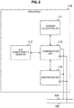
- FIG. 2 is a block diagram illustrating an exemplary configuration of the processor 110 in the first embodiment.
- the processor 110 includes an address allocation unit 111, a bus characteristic register 112, a communication unit 113 and an arbitration unit 114.
- the processor 140 has the similar configuration as the processor 110. Note that the processor 110 is an example of the master device described in the appended claims.
- the address allocation unit 111 allocates a dynamic address to each slave.
- the dynamic address is information for identifying the slave, and a unique address is allocated for each slave.
- the address allocation unit 111 starts dynamic address allocation (assignment) when power is applied to the electronic device 100.
- the address allocation unit 111 reads data from a bus characteristic register (BCR) of each device when allocation is performed, for example.
- BCR bus characteristic register
- the BCR is a register in which setting information necessary when the dynamic address is allocated such as a role of the device is stored and is a read-only register. Therefore, the address allocation unit 111 allocates the dynamic address for each slave on the basis of the read setting information.
- the bus characteristic register 112 stores setting information of the processor 110.
- the communication unit 113 performs communication as the master or the slave according to I3C.
- the communication unit 113 outputs data through any of an open drain circuit and a push-pull circuit.
- a communication rate becomes lower than the case where communication is performed using the push-pull circuit due to characteristics of the circuit.
- the open drain circuit data is transmitted in synchronization with a clock signal of 400 kilohertz (kHz).
- kHz kilohertz
- the push-pull circuit data is transmitted in synchronization with a clock signal of 12.5 megahertz (MHz).
- the arbitration unit 114 detects collision and arbitrates devices.
- the arbitration unit 114 monitors a level of the SDA line 108, and in the case where a value of a bit transmitted by the device (the processor 140) is different from a value of a bit in transmission using the SDA line 108, determines that there is collision.
- arbitration is performed, for example, a device that has transmitted "0" has priority and a device that has transmitted "1" loses a control right.
- FIG. 3 is a block diagram illustrating an exemplary configuration of the display driver 120 in the first embodiment.
- the display driver 120 includes a bus characteristic register 121, a communication unit 122 and an arbitration unit 123.
- the gyro sensor 130 has a similar configuration as the display driver 120.
- the bus characteristic register 112 stores setting information of the display driver 120.
- the communication unit 122 performs communication as the slave according to I3C.
- the arbitration unit 123 detects collision and arbitrates devices.
- FIG. 4 is a diagram for describing a communication scheme in the first embodiment.
- three schemes are defined as communication schemes. Hereinafter, these schemes are referred to as a case 0, a case 1 and a case 2.
- a header type of type 0 is set.
- a 7-bit fixed pattern data called "reserved” is first transmitted by the master.
- the pattern data for example, a hexadecimal value of "7E” (a binary value of "1111110") is set.
- a 7-bit dynamic address allocated to an access destination slave is transmitted by the master. It is possible to connect a maximum of 112 slaves to the master using the 7-bit dynamic address.
- a transmission source device in the type 0 transmits the reserved using the open drain circuit.
- the device since the communication rate decreases as described above, the device can detect collision in units of bits and perform arbitration.
- a header type of type 1 is set.
- the reserved is first transmitted by the master.
- a 7-bit dynamic address whose first bit A[6] is fixed to "0" is transmitted by the master.
- the first bit of the dynamic address is fixed to "0" so that the device detects collision in the first bit.
- a slave that performs the in-band interrupt or the like first transmits a dynamic address whose first bit is "0.”
- the master first transmits a reserved whose first bit is "1" as described above.
- the device can perform arbitration by monitoring a level of the SDA line 108 and detecting whether collision has occurred when the first bit is transmitted.
- the first bit is fixed to "0,” a size of the address that is substantially available is reduced to 6 bits from 7 bits, and the number of slaves is reduced by half from a maximum of 112 to a maximum of 56.
- the first bit in order to detect collision, the first bit is transmitted by the open drain circuit having a relatively low communication rate.
- second and subsequent bits are transmitted by the push-pull circuit having a relatively high communication rate. Accordingly, an overall communication rate of the case 1 is higher than that of the case 0.
- a header type of type 1 is set.
- a 7-bit dynamic address is first transmitted by the master without transmitting the reserved.
- the device is unable to perform arbitration. Since the device does not perform arbitration, the first bit of the dynamic address is not set as a fixed value, and the number of connectable slaves is 112, similarly to the case 0. Further, since no reserved is transmitted, the case 2 has a higher communication rate than either of the cases 0 and 1.
- the case 1 has a smaller number of slaves and a higher communication rate than the case 0.
- the case 2 has the same number of slaves as the case 0 and has a higher communication rate than the case 0, but arbitration is not possible. In this manner, all schemes have advantages and disadvantages.
- a header type of a reserved is set as a type 1.
- the reserved is first transmitted by the master.
- a 7-bit dynamic address whose first bit A[6] is set as a group identifier is transmitted by the master.
- the group identifier is a bit indicating whether the slave belongs to a group for which arbitration is necessary.
- the group identifier can be set in the BCR such that a signal (the in-band interrupt or the like) that may collide with a signal from another device can be transmitted by the slave and, in addition, it is possible to set such that a signal can be transmitted only under control of the master.
- the master classifies a slave that can transmit a signal for which collision may occur as a group for which arbitration is necessary and classifies the other slaves as a group for which arbitration is unnecessary.
- the group identifier of the group for which arbitration is necessary is set to "0.”
- the group identifier of the group for which arbitration is unnecessary is set to "1.”
- a first bit (a group identifier) of a dynamic address of a slave for which arbitration is not necessary is "1.” While this value is the same as that of the first bit of the reserved, since the slave is unable to transmit the dynamic address, it is irrelevant to collision.
- the number of connectable slaves is greater than that of the case 1 in which it is necessary to fix the first bit.
- the header type is the type 1
- the communication rate is higher than that of the case 0, similarly to the case 1.
- slave the display driver 120 or the like
- the slave in the group for which arbitration is not necessary is an example of the second slave device described in the appended claims.
- Each of the devices (the processor 110 and the like) in the electronic device 100 appropriately selects any of the above cases 0 to 3 depending on a situation and performs communication with other devices.
- FIG. 5 is a diagram for describing a header type in the first embodiment.
- FIG. 5a is a diagram illustrating an exemplary state of the SDA line 108 and the SCL line 109 when a header (a reserved) of the type 0 is transmitted.
- FIG. 5b is a diagram illustrating an exemplary state of the SDA line 108 and the SCL line 109 when a header of the type 1 is transmitted.
- A[6] to A[0] each indicate 7 bits of the reserved. In the reserved, A[6] is transmitted first and A[0] is transmitted last.
- R/W is a read-write bit indicating any of data write and read.
- the master When communication starts, the master sets the SDA line 108 to a low level and the SCL line 109 to a high level. This state is referred to as a start condition S.
- the master sequentially transmits A[6] to A[0] and R/W in synchronization with a clock signal following the start condition S (a start bit).
- all bits are transmitted by the open drain circuit having a low communication rate.
- the type 1 only the first bit A[6] is transmitted by the open drain circuit, and second and subsequent bits are transmitted by the push-pull circuit having a high communication rate.
- a communication rate of all bits is low but arbitration is performed for each bit.
- arbitration is performed only in the first bit, but if there is no collision in the first bit, a communication rate of second and subsequent bits becomes higher than that of the type 0. Note that, when collision occurs in the first bit of the type 1, the device transmits second and subsequent bits by the open drain circuit and performs arbitration for each bit.
- FIG. 6 is a diagram illustrating an exemplary data structure of a frame that is transmitted by the master in the cases 0 to 2 in the first embodiment.
- the frame refers to a signal including a dynamic address, and data transmitted and received by a slave having the dynamic address.
- FIG. 6a illustrates an exemplary configuration of a frame that is transmitted when the master performs write in the case 0.
- FIG. 6b illustrates an exemplary configuration of a frame that is transmitted when the master performs read in the case 0.
- FIG. 6c illustrates an exemplary configuration of a frame that is transmitted when the master performs write in the case 1.
- FIG. 6d illustrates an exemplary configuration of a frame that is transmitted when the master performs read in the case 1.
- FIG. 6a illustrates an exemplary configuration of a frame that is transmitted when the master performs read in the case 1.
- FIG. 6e illustrates an exemplary configuration of a frame that is transmitted when the master performs write in the case 2.
- FIG. 6f illustrates an exemplary configuration of a frame that is transmitted when the master performs read in the case 2.
- a white rectangle indicates a signal that is transmitted from the master to the slave
- a shaded rectangle indicates a signal that is transmitted from the slave to the master.
- the start condition S is first transmitted from the master, and a reserved having a hexadecimal value of "7E" and a read-write bit R/W are sequentially transmitted from the master. Then, in the case where the slave has successfully received, an acknowledge (ACK) is transmitted from the slave. Following the ACK, a restart condition Sr is transmitted by the master, and a dynamic address and a read-write bit R/W are sequentially transmitted. Then, in the case where the slave has successfully received these, an ACK is transmitted from the slave. Following the ACK, read data or write data is transmitted and received between the master and the slave. The data is transmitted in units of bytes, and a parity called a transition bit T is added to each byte. When the data is completely transmitted and received, a stop condition P or the restart condition Sr is transmitted by the master.
- the reserved is transmitted from the master, and the ACK is transmitted from the slave.
- the restart condition Sr is transmitted by the master, and a dynamic address whose first bit A[6] is set to "0" and a read-write bit R/W are sequentially transmitted.
- the ACK is transmitted from the slave, and read data or write data is transmitted and received between the master and the slave.
- the stop condition P or the restart condition Sr is transmitted by the master.
- the dynamic address is transmitted from the master, and the ACK is transmitted from the slave.
- read data or write data is transmitted and received between the master and the slave.
- the stop condition P or the restart condition Sr is transmitted by the master.
- FIG. 7 is a diagram illustrating an exemplary data structure of a frame that is transmitted by the master in the case 3 in the first embodiment.
- FIG. 7a illustrates an exemplary configuration of a frame that is transmitted when the master performs write in the case 3.
- FIG. 7b illustrates an exemplary configuration of a frame that is transmitted when the master performs read in the case 3.
- the reserved is transmitted from the master, and the ACK is transmitted from the slave.
- the restart condition Sr is transmitted by the master, and the dynamic address whose first bit A[6] is set as a group identifier and a read-write bit R/W are sequentially transmitted.
- the group identifier in the case where the slave belongs to an arbitration target group for which arbitration is necessary, "0" is set, and in the case where the slave belongs to an arbitration-unnecessary group, "1" is set.
- the ACK is transmitted from the slave, and read data or write data is transmitted and received between the master and the slave.
- the stop condition P or the restart condition Sr is transmitted by the master.
- the device can detect collision in the first bit and perform arbitration.
- FIG. 8 is a diagram illustrating an exemplary data structure of a frame that is transmitted by the slave in the first embodiment.
- FIG. 8a illustrates an exemplary configuration of a frame that is transmitted when the slave performs write by the in-band interrupt or the like in the case 0.
- FIG. 8b illustrates an exemplary configuration of a frame that is transmitted when the slave performs read by the in-band interrupt or the like in the case 0.
- FIG. 8c illustrates an exemplary configuration of a frame that is transmitted when the slave performs write by the in-band interrupt or the like in the case 1.
- FIG. 8d illustrates an exemplary configuration of a frame that is transmitted when the slave performs read by the in-band interrupt or the like in the case 1.
- FIG. 8a illustrates an exemplary configuration of a frame that is transmitted when the slave performs read by the in-band interrupt or the like in the case 1.
- FIG. 8e illustrates an exemplary configuration of a frame that is transmitted when the slave performs write by the in-band interrupt or the like in the case 3.
- FIG. 8f illustrates an exemplary configuration of a frame that is transmitted when the slave performs read by the in-band interrupt or the like in the case 3. Note that, in the case 2, the slave does not transmit the dynamic address to the master. This is because the device is unable to perform arbitration in the case 2.
- the start condition S and the dynamic address are transmitted by the slave, and the ACK is transmitted by the master.
- the restart condition Sr is transmitted by the master, and read data or write data is transmitted and received between the master and the slave. Also, immediately after the ACK is transmitted, the master may transmit the stop condition P.
- the start condition S and the dynamic address whose first bit A[6] is fixed to "0" are transmitted by the slave, and the ACK is transmitted by the master.
- the restart condition Sr is transmitted by the master and read data or write data is transmitted and received between the master and the slave.
- the dynamic address whose first bit A[6] is set as a group identifier is transmitted from the slave, and the ACK is transmitted by the master. Since "0" is set to the group identifier in the slave that performs the in-band interrupt or the like, the device detects whether collision has occurred, similarly to the case 1.
- the restart condition Sr is transmitted by the master, and read data or write data is transmitted and received between the master and the slave.
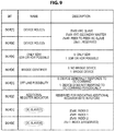
- FIG. 9 is a diagram illustrating an example of setting information of the bus characteristic register 112 in the first embodiment.
- BCR[7] to BCR[0] are stored in the bus characteristic register 112.
- BCR[i] (i is an integer of 0 to 7) indicates an i-th bit.
- Such a bit includes setting information indicating whether the slave belongs to the group for which arbitration is necessary.
- parts surrounded by dotted lines indicate parts of specifications of I3C that are modified according to addition of the case 3.
- BCR[7] and BCR[6] a role (a device role) allocated to the device in the system such as the master or the slave is set.
- a binary value of "01" is set.
- a binary value of "10” is set.
- any of indexes 0 to 3 indicating whether the device performs the in-band interrupt and setting content related to a clock frequency is set.
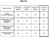
- FIG. 10 is a diagram illustrating exemplary details of the indexes 0 to 3 in the first embodiment.
- parts surrounded by dotted lines and a bold frame parts indicate parts of specifications of I3C that are modified according to addition of to the case 3.
- the index 0 indicates that an in-band interrupt request is performed and it is possible to set the clock frequency to the maximum.
- the index 1 indicates that the in-band interrupt request is performed and it is not possible to set the clock frequency to the maximum.
- the index 2 indicates that no in-band interrupt request is performed and it is not possible to set the clock frequency to the maximum.
- the index 3 indicates that no in-band interrupt request is performed and it is possible to set the clock frequency to the maximum.
- the master determines the device as a slave for which arbitration is necessary and sets the group identifier as "0.”
- FIG. 11 is a flowchart illustrating exemplary operations of a master/slave device (the processor 110 or the like) in the first embodiment.
- the operation starts when, for example, power is applied to the electronic device 100.
- the device reads a bus characteristic register or the like from each slave (Step S911), and performs an address allocation process for allocating a dynamic address (Step S920).
- the device determines whether a start condition generated by another device is detected (Step 912). In the case where the start condition is not detected (No in Step S912), the device determines whether a predetermined event for communication has occurred (Step S913). In the case where the event has occurred (Yes in Step S913), the device performs a master side communication process (Step S930). In the case where the event has not occurred (No in Step S913) or after Step S930, the device repeats processes after Step S912.
- Step S912 the master starts generation of a clock signal (Step S914), receives a dynamic address, and performs arbitration when collision has occurred (Step S915). Then, the master determines whether the received address is allocated to the master itself (Step S916). In the case where an own address is received (Yes in Step S916), the device transmits an ACK, transmits and receives data, and performs a process of the received data (Step S917). In the case where the own address is not received (No in Step S916), or after Step S917, the device repeats processes after Step S912.
- FIG. 12 is a flowchart illustrating an exemplary address allocation process of the case 3 in the first embodiment.
- the device determines whether a current communication scheme is the case 3 (Step S921). In the case where the current communication scheme is not the case 3 (No in Step S921), the device performs a dynamic address allocation process corresponding to any of the cases 0 to 2 as the master (Step S922), and ends the address allocation process.
- the device selects an allocation target slave as the master, and determines whether the slave is a slave in the group for which arbitration is necessary on the basis of the BCR (Step S923). In the case where the slave is in the group for which arbitration is necessary (Yes in Step S923), the device allocates a dynamic address whose first bit A[6] is set to "0" (Step S924). On the other hand, in the case where the slave is not in the group for which arbitration is necessary (No in Step S923), the device allocates a dynamic address whose first bit A[6] is set to "1" (Step S926).
- Step S925 or S926 the device determines whether addresses of all slaves are completely allocated (Step S927). In the case where allocation is not completed (No in Step S927), the device repeats processes after Step S923. In the case where allocation is completed (Yes in Step S927), the address allocation process ends.
- FIG. 13 is a flowchart illustrating an exemplary master side communication process in the first embodiment.
- the device determines whether the current communication scheme is the case 3 (Step S931). In the case where the current communication scheme is the case 3 (Yes in Step S931), the device performs a communication process corresponding to the case 3 (Step S940). On the other hand, in the case where the current communication scheme is not the case 3 (No in Step S931), the device performs a communication process corresponding to any of the cases 0 to 2 (Step S932). After Step S940 or S932, the device ends the master side communication process.
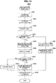
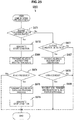
- FIG. 14 is a flowchart illustrating an exemplary master side communication process corresponding to the case 3 in the first embodiment.
- Step S944 When collision has occurred (Yes in Step S944), the master loses a control right, stops transmission to the SDA line 108, receives an address of second and subsequent bits from another slave, and performs arbitration in units of bits (Step S945).
- the open drain circuit having a low communication rate is used.
- the device analyzes which of multi-master communication, peer-to-peer communication, and in-band interrupt has occurred on the basis of the received signal (Step S946). In addition, the device determines as the master whether the in-band interrupt is acceptable (Step S947). In the case where the in-band interrupt is acceptable (Yes in Step S947), the master transmits an ACK, transmits and receives data, and performs a process of the received data (Step S948). Such data is transmitted by the push-pull circuit. On the other hand, in the case where the in-band interrupt is unacceptable (No in Step S947), the master transmits a NACK (Step S948).
- Step S944 the device transmits second and subsequent bits of the pattern data (reserved), and a dynamic address of an access destination (Step S951).
- the push-pull circuit having a relatively high communication rate is used. Therefore, the device transmits and receives data and performs a process of the received data (Step S952).
- Step S951 the device generates a stop condition (Step S951), and ends the master side communication process of the case 3.
- FIG. 15 is a flowchart illustrating an exemplary operation of the slave (for example, the display driver 120) in the first embodiment.
- the operation starts when, for example, power is applied to the electronic device 100.
- the slave stores the dynamic address allocated by the master (Step S961), and determines whether the current communication scheme is the case 3 (Step S962). In the case where the current communication scheme is the case 3 (Yes in Step S962), the slave performs a slave side communication process of the case 3 (Step S970), and repeats processes after Step S962. On the other hand, in the case where the current communication scheme is not the case 3 (No in Step S962), the slave performs a communication process corresponding to any of the cases 0 to 2 (Step S963), and repeats processes after Step S962.
- FIG. 16 is a flowchart illustrating an exemplary slave side communication process corresponding to the case 3 in the first embodiment.
- the device determines whether a predetermined event for the in-band interrupt or peer-to-peer communication has occurred (Step S971).
- Step S971 the slave generates a start condition (Step S972). Then, the slave transmits an own dynamic address and performs arbitration when collision has occurred (Step S973). The slave determines whether an ACK is received (Step S974). In the case where the ACK is received (Yes in Step S974), the slave transmits and receives data and performs a process of the received data (Step S975), and generates a stop condition (Step S976). In the case where no ACK is received (No in Step S974), or after Step S976, the slave ends the slave side communication process of the case 3.
- Step S977 the slave determines whether a start condition generated by another device is detected.
- the slave receives a fixed pattern and a dynamic address, and performs arbitration when collision has occurred (Step S978). Therefore, the device determines whether the received address is the own address (Step S979).
- the device transmits and receives data and performs a process of the received data (Step S980).
- the slave ends the communication process.
- the address in which a value different from the first bit of the pattern data is set to the first bit is allocated to the slave that performs the interrupt or the like, it is possible to detect whether collision has occurred in each first bit of the pattern data and the address. Accordingly, the device that has detected collision can arbitrate devices that have transmitted the signal that has collided.
- the first bit of the address is not a fixed value, it is possible to connect a greater number of slaves than in the case 1 in which the first bit is set as a fixed value.
- the master can alternatively modify other parts of the BCR.
- a device role of the reserved in the BCR can be used.
- the electronic device 100 in a first modification of the first embodiment is different from that of the first embodiment in that the device role of the reserved in the BCR is modified.
- FIG. 17 is a diagram illustrating an example of setting information of the bus characteristic register 112 in the first modification of the first embodiment.
- a part surrounded by a dotted line indicates a part of specifications of I3C that is modified according to addition of the case 3.
- the reserved is set in "11."
- the role is modified to a slave that does not request any of the in-band interrupt, a secondary master request, and a peer to peer slave request.
- the master of the first modification determines a slave in which "11" is set in BCR[7] and BCR[6] in the case 3 as a "slave for which arbitration is not necessary” and determines the other slaves as "slaves for which arbitration is necessary.”
- the master can alternatively modify other parts of the BCR.
- the device role of the reserved in the BCR can be used.
- the electronic device 100 in a second modification of the first embodiment is different from that of the first embodiment in that the device role of the reserved in the BCR is modified.
- FIG. 18 is a diagram illustrating an example of setting information of the bus characteristic register 112 in the second modification of the first embodiment.
- a part surrounded by a dotted line indicates a part of specifications of I3C to that is modified according to addition of the case 3.
- the master determines a slave in which "01" (a secondary master), "10" (a peer to peer slave), or "11" (a slave that performs the in-band interrupt) is set in BCR[7] and BCR[6] in the case 3 as a "slave for which arbitration is necessary.”
- a slave in which "00" is set in CR[6] and BCR[7] is determined as a "slave for which arbitration is not necessary.”
- the slave for which arbitration is not necessary is allocated to the device role ("11") of the reserved.
- the slave for which arbitration is necessary is allocated to "11." In addition, in the modification 1, the slave for which arbitration is necessary is allocated to "00.” On the other hand, in the modification 2, the slave for which arbitration is not necessary is allocated to "00.”
- the master can alternatively modify other parts of the BCR.
- the number of bits allocated to the device role in the BCR increased from 2 bits to 3 bits, and empty parts can be used.
- the electronic device 100 in a third modification of the first embodiment is different from that of the first embodiment in that the number of bits allocated to the device role in the BCR is increased.
- FIG. 19 is a diagram illustrating an example of setting information of the bus characteristic register 112 in the third modification of the first embodiment.
- parts surrounded by bold lines and dotted lines indicate parts of specifications of I3C that are modified according to addition of the case 3.
- Bits allocated to the device role are modified from BCR[6] and BCR[7] to BCR[5] to BCR[7]. According to such a modification, the modification is performed such that information set in BCR[5] to [2] before modification is moved to BCR[4] to [1]. In addition, in BCR[0], a possibility of setting a maximum SCL clock frequency is set.
- BCR[5] to BCR[7] a binary value of "000” indicates that the device is an I2C slave, and "100” indicates that the device is an I2C secondary master.
- "010” indicates that the device is a peer to peer I3C slave, and "001” indicates that the device is a slave that performs the in-band interrupt. The reserved is set in the others.
- the master determines a slave in which "100,” “100,” or “010” is set in BCR[5] to BCR[7] in the case 3 as a “slave for which arbitration is necessary.”
- the address having a first bit different from that of the fixed pattern is allocated to the slave that performs the interrupt or the like. Accordingly, the communication rate increases and the number of devices increases, compared to the case 0.
- a system that desires a higher communication rate than that of the case 0 and a possibility of arbitration rather than the increased number of devices is assumed.
- a second embodiment is different from the first embodiment in that the electronic device 100 has a higher communication rate than that of the case 0 and is able to arbitrate.
- FIG. 20 is a diagram for describing a communication scheme in the second embodiment.
- a case 4 is added in addition to the cases 0 to 3.
- a header type of type 1 is set.
- a 7-bit dynamic address is transmitted by the master following a start condition without transmitting a fixed pattern of a reserved.
- an arbitration bit is set in the first bit of the dynamic address. In the arbitration bit, a fixed value of "1" is set on the master side, and a fixed value of "0" is set on the slave side.
- the case 4 since a fixed value is set in the first bit, a size of the address that is substantially available is reduced to 6 bits from 7 bits, and the number of slaves is reduced by half from a maximum of 112 to a maximum of 56.
- the device can detect collision in the first bit and perform arbitration.
- transmission of the reserved since transmission of the reserved is unnecessary, the case 4 has a higher communication rate than the case 0, the case 1, or the case 3 in which transmission of the reserved is necessary.
- FIG. 21 is a diagram illustrating an exemplary data structure of a frame that is transmitted by the master in the case 4 in the second embodiment.
- a dynamic address is transmitted from the master, and an ACK is transmitted from the slave.
- "1" is set in the first bit (the arbitration bit) of the dynamic address.
- "0" is set in the first bit of the dynamic address that is transmitted by the slave.
- the master allocates the dynamic address in the similar procedure as in the case 1. That is, the first bit of the dynamic address of the slave is fixed to "0.”
- an arbitration-unnecessary slave that does not perform the in-band interrupt or the like
- the other of the master and the slave may erroneously determine that the access is directed to itself. For example, a case in which only a first bit is different between an address of the arbitration-unnecessary slave and an address of the master or slave, and 6 lower bits are the same is assumed. In such a configuration, when the control right is lost, since the first bit (the arbitration bit) is set from "1" to "0,” the master or slave erroneously determines the address transmitted to the arbitration-unnecessary slave as its own address.
- the master allocate an address whose 6 lower bits are different from a dynamic address of an arbitration target slave that performs the in-band interrupt or the like to the arbitration-unnecessary slave.
- FIG. 22 is a flowchart illustrating an exemplary master side communication process in the second embodiment.
- the communication process of the second embodiment is different from that of the first embodiment in that Steps S933 and S955 are further performed.
- the device determines whether the current communication scheme is the case 4 (Step S933). In the case where the current communication scheme is the case 4 (Yes in Step S933), the device performs a master side communication process corresponding to the case 4 (Step S955), and ends the master side communication process. On the other hand, in the case where the current communication scheme is not the case 4 (No in Step S933), the device performs Step S932.
- FIG. 23 is a flowchart illustrating an exemplary master side communication process corresponding to the case 4 in the second embodiment.
- the communication process of the case 4 is similar to the communication process of the case 3 except that Step S956 is performed in place of Step S949.
- the device transmits second and subsequent bits of the address by the push-pull circuit (Step S956), and performs processes after Step S950.
- FIG. 24 is a flowchart illustrating an exemplary slave side communication process in the second embodiment.
- the slave side communication process of the second embodiment is different from that of the first embodiment in that Steps S964 and S985 are further performed.
- Step S964 the device determines whether the current communication scheme is the case 4. In the case where the current communication scheme is the case 4 (Yes in Step S964), the device performs a slave side communication process corresponding to the case 4 (Step S985), and repeats processes after Step S962. On the other hand, in the case where the current communication scheme is not the case 4 (No in Step S964), the device performs Step S963.
- FIG. 25 is a flowchart illustrating an exemplary slave side communication process corresponding to the case 4 in the second embodiment.
- the communication process of the case 4 is similar to the communication process of the case 3 except that Steps S986 and S987 are performed in place of Steps S973 and S978.
- the slave In the case where an event for the interrupt or the like has occurred (Yes in Step S971), the slave generates a start condition (Step S972). Therefore, the slave transmits an address whose first bit (arbitration bit) A[6] is set to "0,” performs arbitration when collision has occurred (Step S986), and performs processes after Step S974.
- the slave transmits the dynamic address, performs arbitration when collision has occurred (Step S987), and performs processes after Step S979.
- the master and the slave since the master and the slave transmit dynamic addresses in which different fixed values are set in the first bits following the start condition, it is possible to detect collision in the first bit and perform arbitration. In addition, it is possible to increase the communication rate compared to the case 0 or the like in which pattern data is transmitted.
- processing sequences described in the above embodiments may be prepared as a method including such series of procedures, or a program causing a computer to execute such series of procedures or a recording medium recording the program.
- a recording medium for example, a compact disc (CD), a MiniDisc (MD), a digital versatile disc (DVD), a memory card, a Blu-ray (registered trademark) disc, and the like can be used.
Landscapes
- Engineering & Computer Science (AREA)
- Theoretical Computer Science (AREA)
- General Engineering & Computer Science (AREA)
- Physics & Mathematics (AREA)
- General Physics & Mathematics (AREA)
- Computer Hardware Design (AREA)
- Information Transfer Systems (AREA)
- Small-Scale Networks (AREA)
- Bus Control (AREA)
- Alarm Systems (AREA)
- Selective Calling Equipment (AREA)
- Circuits Of Receivers In General (AREA)
Abstract
Description
- The present technology relates to a communication system, a device, a master device, a slave device, a communication system control method, and a program causing a computer to execute the method, and specifically, to a communication system configured to transmit and receive data between a master and a slave, a device, a master device, a slave device, a communication system control method, and a program causing a computer to execute the method.
- In the related art, when communication is performed between devices in a relatively short range, for example, within the same substrate, a communication standard of Inter-Integrated Circuit (I2C) is broadly used due to a simple configuration. In I2C, since a plurality of masters can transmit signals to one slave, it is necessary to detect collision of such signals and arbitrate the masters. For example, in the communication standard of I2C, an arbitration procedure in which, when one master transmits "1" and the other master transmits "0," the master that has transmitted "1" loses a control right is proposed (for example, refer to Non-Patent Literature 1).
- In addition, a communication standard of I3C, an extended version of I2C, is proposed. In I3C, three communication schemes are used. In the first communication scheme (hereinafter referred to as a "
case 0"), it is possible to connect a maximum of 112 slaves to the master while arbitration is possible. In the second communication scheme (hereinafter referred to as a "case 1"), a higher communication rate than that of thecase 0 is provided, but the number of connectable slaves is limited to a maximum of 56 while arbitration is possible. In the third communication scheme (hereinafter referred to as a "case 2"), a higher communication rate than that of thecase 0 is provided, and it is possible to connect a maximum of 112 slaves, but it is not possible to arbitrate devices. - Non-Patent Literature 1: "UM10204 bus I2C bus specification and user manual Rev5.0J," [online], October 9, 2012, NXP semiconductors, [August 26, 2015, search], Internet (http://www.nxp.com/documents/user_manual/UM10204_JA.pdf)
- In the related art described above, there is a problem in that it is difficult to optimize a system using I3C. For example, in the
case 1, it is possible to increase a communication rate while arbitration is possible, but the number of connectable slaves is smaller than that of thecase 0. In addition, in thecase 2, it is possible to increase a communication rate while the number of slaves is similar to that of thecase 0, but arbitration is not possible. In this manner, there is a problem in that it is difficult to optimize a system with a balance between the number of connectable slaves and a possibility of arbitration. - In view of such problems, the present technology is provided to optimize a system configured to transmit and receive data between a master and a slave.
- The present technology has been made in order to solve the above-mentioned issues. According to a first aspect of the present technology, there are provided a communication system including: a first slave device that belongs to a group for which arbitration is necessary and configured to sequentially transmit a start bit indicating communication start and a first address in which a value different from a first bit of predetermined pattern data is set in a first bit, and transmit and receive data; and a master device configured to sequentially transmit the start bit and the predetermined pattern data, in which the master device arbitrates the master device and the first slave device on a basis of the first bit, and a communication system control method and a program causing a computer to execute the method. Accordingly, there is provided an effect in which the master device and the first slave device are arbitrated on a basis of the first bit.
- Further, according to the first aspect, there may be further included a second slave device configured to receive a second address in which a specific value is set in a first bit after the start bit and the predetermined pattern data are sequentially received, and transmit and receive data. Accordingly, there is provided an effect in which the second address in which a specific value is set in a first bit is received.
- Further, according to the first aspect, the second slave device may transmit an acknowledgment after the start bit and the predetermined pattern data are sequentially received, may receive a restart condition indicating communication restart, and may receive the second address. Accordingly, there is provided an effect in which the restart condition and the second address are received.
- Further, according to the first aspect, the master device and the first and second slave devices may transmit and receive the data according to a communication standard of I3C. Accordingly, there is provided an effect in which the data is transmitted and received according to the communication standard of I3C.
- Further, according to the first aspect, the first slave device may be a device that is able to perform an I3C secondary master request in the communication standard of I3C. Accordingly, there is provided an effect in which the master device and the device that is able to perform an I3C secondary master request are arbitrated on a basis of the first bit.
- Further, according to the first aspect, the first slave device may be a device that is able to perform a peer to peer I3C slave request in the communication standard of I3C. Accordingly, there is provided an effect in which the master device and the device that is able to perform a peer to peer I3C slave request are arbitrated on a basis of the first bit.
- Further, according to the first aspect, the first slave device may be a device that is able to perform an in-band interrupt in the communication standard of I3C. Accordingly, there is provided an effect in which the master device and the device that is able to perform an in-band interrupt are arbitrated on a basis of the first bit.
- Further, according to the first aspect, the first slave device may store setting information indicating inclusion in a group for which arbitration is necessary, the second slave device may store the setting information indicating inclusion in a group for which arbitration is unnecessary, and the master device may allocate the first address to the first slave device and may allocate the second address to the second slave device on a basis of the setting information. Accordingly, there is provided an effect in which the first address is allocated to the first slave device and the second address is allocated to the second slave device on a basis of the setting information.
- Further, according to the first aspect, the first and second slave devices may store the setting information in a bus characteristic register. Accordingly, there is provided an effect in which the first address is allocated to the first slave device and the second address is allocated to the second slave device on a basis of the setting information stored in a bus characteristic register.
- Further, according to a second aspect of the present technology, there is provided a device to which an address in which inclusion or non-inclusion in a group for which arbitration is necessary is set in a first bit is allocated. Accordingly, there is provided an effect in which the device is arbitrated on a basis of a first bit.
- Further, according to a third aspect of the present technology, there is provided a master device including: a communication unit configured to sequentially transmit a start bit indicating communication start, predetermined pattern data, and an address in which inclusion or non-inclusion in a group for which arbitration is necessary is set in a first bit; and an arbitration unit configured to arbitrate a slave device and another device on a basis of the first bit. Accordingly, there is provided an effect in which the master device and the other device are arbitrated on a basis of the first bit.
- Further, according to the third aspect, the communication unit may receive an acknowledgment after the start bit and the predetermined pattern data are sequentially transmitted, may transmit a restart condition indicating communication restart, and may transmit the address. Accordingly, there is provided an effect in which the restart condition and a second address are transmitted.
- Further, according to the third aspect, when a value different from a first bit of the predetermined pattern data is detected in the arbitration based on the first bit performed by the arbitration unit, the communication unit may determine that an event that includes an in-band interrupt request, a secondary master request, or a peer to peer slave request and for which arbitration is necessary has occurred and may stop transmission of the predetermined pattern data, the arbitration unit may receive an address of second and subsequent bits from the slave device and may perform arbitration in units of bits, and the communication unit may transmit an acknowledgment, and then may transmit and receive data or may perform a process of data in a case where the master device is able to accept the event, and may end a communication process without transmitting the acknowledgment in a case where the master device is unable to accept the event. Accordingly, there is provided an effect in which arbitration is performed in units of bits.
- Further, according to a fourth aspect of the present technology, there is provided a slave device including: a transmission unit configured to sequentially transmit a start bit indicating communication start and an address in which inclusion or non-inclusion in a group for which arbitration is necessary is set in a first bit; and an arbitration unit configured to arbitrate a master device and a slave device on a basis of the first bit. Accordingly, there is provided an effect in which the slave device and another device are arbitrated on a basis of the first bit.
- Further, according to a fifth aspect of the present technology, there is provided a communication system including: a slave device configured to sequentially transmit a start bit indicating communication start and a transmission source address in which a specific value is set in a first bit; and a master device configured to sequentially transmit the start bit and a transmission destination address in which a value that does not correspond to the specific value is set in a first bit and arbitrate the slave device and another device on a basis of the first bit. Accordingly, there is provided an effect in which the slave device and the other device are arbitrated on a basis of the first bit by the master device.
- Further, according to the fifth aspect, the slave device may include an arbitration target slave device for which an arbitration process is necessary and an arbitration-unnecessary slave device for which an arbitration process is unnecessary, and the master device may allocate the address to the arbitration target device and may allocate an address in which a bit string except for a first bit is different from a bit string of the arbitration target slave device to the arbitration-unnecessary device. Accordingly, there is provided an effect in which the address is allocated to the arbitration target device and the address in which a bit string except for a first bit is different from a bit string of the arbitration target slave device is allocated to the arbitration-unnecessary device.
- Further, according to a sixth aspect of the present technology, there is provided a device configured to sequentially transmit a start bit indicating communication start and a transmission source address in which a fixed value is set in a first bit. Accordingly, there is provided an effect in which the device configured to sequentially transmit a start bit and a transmission source address in which a fixed value is set in a first bit is arbitrated.
- Further, according to a seventh aspect of the present technology, there is provided a device including: a transmission unit configured to sequentially transmit a start bit indicating communication start and a transmission destination address in which a fixed value is set in a first bit; and an arbitration unit configured to arbitrate a slave device and another device on a basis of the first bit. Accordingly, there is provided an effect in which the device is arbitrated on a basis of the first bit.
- Further, according to an eighth aspect of the present technology, there is provided a communication system including: a master device configured to sequentially transmit a start bit indicating communication start and predetermined pattern data, and transmit and receive data; and a first slave device that is able to perform an in-band interrupt request, a secondary master request, or a peer to peer slave request, in which the first slave device sequentially transmits the start bit and a first address in which a value different from a first bit of the predetermined pattern data is set in a first bit, and transmits and receives data, and the master device arbitrates the master device and the first slave device on a basis of the first bit. Accordingly, there is provided an effect in which the master device and the first slave device are arbitrated on a basis of the first bit.
- Further, according to the eighth aspect, there may be further included a second slave device that does not perform any of the in-band interrupt request, the secondary master request, and the peer to peer slave request, and the second slave device may receive a second address in which a specific value is set in a first bit after the start bit and the predetermined pattern data are sequentially received, and may transmit and receive data. Accordingly, there is provided an effect in which the second address in which a specific value is set in a first bit is received after the start bit and the predetermined pattern data.
- Further, according to the eighth aspect, the second slave device may transmit an acknowledgment after the start bit and the predetermined pattern data are sequentially received, may receive a restart condition indicating communication restart, and then may receive an address, and in a case where the received address matches an address of the second slave device allocated from a master, may transmit an acknowledgment, and then may perform reception of write data transmitted from the master device or transmission of read data to the master device, and the first slave device may transmit an acknowledgment after the start bit and the predetermined pattern data are sequentially received in a case where any of the in-band interrupt request, the secondary master request, and the peer to peer slave request is not performed, may receive the restart condition, and then may receive an address, and in a case where the received address matches an address of the first slave device allocated from the master device, may transmit an acknowledgment and then may perform reception of write data transmitted from the master device or transmission of read data to the master device. Accordingly, there is provided an effect in which the acknowledgment is transmitted after the start bit and the predetermined pattern data.
- Further, according to the eighth aspect, the master device and the first and second slave devices may transmit and receive the data according to a communication standard of I3C. Accordingly, there is provided an effect in which the data is transmitted and received according to the communication standard of I3C.
- Further, according to the eighth aspect, the first slave device may be a device that is able to perform an I3C secondary master request in the communication standard of I3C. Accordingly, there is provided an effect in which the device that is able to perform an I3C secondary master request and the master device are arbitrated.
- Further, according to the eighth aspect, the first slave device may be a device that is able to perform a peer to peer I3C slave request in the communication standard of I3C. Accordingly, there is provided an effect in which the device that is able to perform a peer to peer I3C slave request and the master device are arbitrated.
- Further, according to the eighth aspect, the first slave device may be a device that is able to perform an in-band interrupt in the communication standard of I3C. Accordingly, there is provided an effect in which the device that is able to perform an in-band interrupt and the master device are arbitrated.
- Further, according to the eighth aspect, the first slave device may store setting information indicating inclusion in a group for which arbitration is necessary, the second slave device may store the setting information indicating inclusion in a group for which arbitration is unnecessary, and the master device may allocate the first address to the first slave device and may allocate the second address to the second slave device on a basis of the setting information. Accordingly, there is provided an effect in which the first address is allocated to the first slave device and the second address is allocated to the second slave device on a basis of the setting information.
- Further, according to the eighth aspect, the first and second slave devices may store the setting information in a bus characteristic register. Accordingly, there is provided an effect in which the first address is allocated to the first slave device and the second address is allocated to the second slave device on a basis of the setting information stored in a bus characteristic register.
- Further, according to the eighth aspect, the group for which arbitration is necessary may be a group including a slave device in which the slave is able to perform the in-band interrupt request. Accordingly, there is provided an effect in which the group including a slave device which is able to perform the in-band interrupt request is arbitrated.
- Further, according to the eighth aspect, the group for which arbitration is necessary may be a group including a slave device in which the slave is able to perform the secondary master request. Accordingly, there is provided an effect in which the group including a slave device which is able to perform the secondary master request is arbitrated.
- Further, according to the eighth aspect, the group for which arbitration is necessary may be a group including a slave device in which the slave is able to perform the peer to peer slave request. Accordingly, there is provided an effect in which the group including a slave device which is able to perform the peer to peer slave request is arbitrated.
- Further, according to the eighth aspect, when a value different from a first bit of the predetermined pattern data is detected in the arbitration based on the first bit, the master device may determine that an event that includes the in-band interrupt request, the secondary master request, or the peer to peer slave request and for which arbitration is necessary has occurred, may stop transmission of the predetermined pattern data, may receive an address of second and subsequent bits from another slave device, may perform arbitration in units of bits, may transmit an acknowledgment and then may transmit and receive data or may perform a process of data in a case where the event is acceptable to the master device, and may end a master side communication process without transmitting the acknowledgment in a case where the event is unacceptable to the master device. Accordingly, there is provided an effect in which arbitration is performed in units of bits.
- According to the embodiments of the present technology, an excellent effect that it is possible to optimize a system configured to transmit and receive data between a master and a slave can be obtained. Note that effects described herein are not necessarily limiting, and any effect described in the present disclosure may be achieved.
-
- [
FIG. 1] FIG. 1 is a block diagram illustrating an exemplary configuration of electronic equipment in a first embodiment of the present technology. - [
FIG. 2] FIG. 2 is a block diagram illustrating an exemplary configuration of a processor in the first embodiment of the present technology. - [
FIG. 3] FIG. 3 is a block diagram illustrating an exemplary configuration of a display driver in the first embodiment of the present technology. - [
FIG. 4] FIG. 4 is a diagram for describing a communication scheme in the first embodiment of the present technology. - [
FIG. 5] FIG. 5 is a diagram for describing a header type in the first embodiment of the present technology. - [
FIG. 6] FIG. 6 is a diagram illustrating an exemplary data structure of a frame that is transmitted by a master incases 0 to 2 in the first embodiment of the present technology. - [
FIG. 7] FIG. 7 is a diagram illustrating an exemplary data structure of a frame that is transmitted by a master in acase 3 in the first embodiment of the present technology. - [
FIG. 8] FIG. 8 is a diagram illustrating an exemplary data structure of a frame that is transmitted by a slave in the first embodiment of the present technology. - [
FIG. 9] FIG. 9 is a diagram illustrating an example of setting information of a bus characteristic register in the first embodiment of the present technology. - [
FIG. 10] FIG. 10 is a diagram illustrating exemplary details ofindexes 0 to 3 in the first embodiment of the present technology. - [
FIG. 11] FIG. 11 is a flowchart illustrating exemplary operations of a master/slave device in the first embodiment of the present technology. - [
FIG. 12] FIG. 12 is a flowchart illustrating an exemplary address allocation process in the first embodiment of the present technology. - [
FIG. 13] FIG. 13 is a flowchart illustrating an exemplary master side communication process in the first embodiment of the present technology. - [
FIG. 14] FIG. 14 is a flowchart illustrating an exemplary master side communication process corresponding to thecase 3 in the first embodiment of the present technology. - [
FIG. 15] FIG. 15 is a flowchart illustrating an exemplary operation of a slave in the first embodiment of the present technology. - [
FIG. 16] FIG. 16 is a flowchart illustrating an exemplary slave side communication process corresponding to thecase 3 in the first embodiment of the present technology. - [
FIG. 17] FIG. 17 is a diagram illustrating an example of setting information of a bit characteristic register in a first modification of the first embodiment of the present technology. - [
FIG. 18] FIG. 18 is a diagram illustrating an example of setting information of a bit characteristic register in a second modification of the first embodiment of the present technology. - [
FIG. 19] FIG. 19 is a diagram illustrating an example of setting information of a bit characteristic register in a third modification of the first embodiment of the present technology. - [
FIG. 20] FIG. 20 is a diagram for describing a communication scheme in a second embodiment of the present technology. - [
FIG. 21] FIG. 21 is a diagram illustrating an exemplary data structure of a frame that is transmitted by a master in acase 4 in the second embodiment of the present technology. - [
FIG. 22] FIG. 22 is a flowchart illustrating an exemplary master side communication process in the second embodiment of the present technology. - [
FIG. 23] FIG. 23 is a flowchart illustrating an exemplary master side communication process corresponding to thecase 4 in the second embodiment of the present technology. - [
FIG. 24] FIG. 24 is a flowchart illustrating an exemplary slave operation in the second embodiment of the present technology. - [
FIG. 25] FIG. 25 is a flowchart illustrating an exemplary slave side communication process corresponding to thecase 4 in the second embodiment of the present technology. - Hereinafter, forms (hereinafter referred to as "embodiments") for implementing the present technology will be described. The description will proceed in the following order.
- 1. First embodiment (an example in which a group identifier is set to a first bit)
- 2. Second embodiment (an example in which a fixed value is set to a first bit)
-
FIG. 1 is a block diagram illustrating an exemplary configuration of anelectronic device 100 in a first embodiment. Theelectronic device 100 includesprocessors display driver 120, agyro sensor 130, a serial data (SDA)line 108, and a serial clock (SCL)line 109. Theprocessor 110, theprocessor 140, thedisplay driver 120 and thegyro sensor 130 are connected to theSDA line 108 and theSCL line 109, and transmit and receive signals through these signal lines according to a communication standard of I3C. Also, while four devices, theprocessor 110, theprocessor 140, thedisplay driver 120 and thegyro sensor 130, are provided in theelectronic device 100, the number of devices is not limited to 4. - The communication standard of I3C is a standard in which communication is performed through two signal lines, the
SDA line 108 configured to transmit data and theSCL line 109 configured to transmit a clock signal. In the standard, the device (theprocessor 110 or the like) is classified as a device that is operated as a master or a slave or a device that is operated as only a slave. For example, theprocessors display driver 120 and thegyro sensor 130 are operated as only a slave. Here, the master is a device configured to control the slave, and the slave is a device that is operated under control of the master. - In addition, in I3C, it is possible to connect a plurality of slaves to one master. In addition, a plurality of masters can transmit a signal to one slave. Hereinafter, such communication will be referred to as "multi-master communication." Further, slaves can communicate with each other without the master, and such communication is referred to as "peer-to-peer communication." In addition, while the
SDA line 108 is in a communication state (busy) due to communication of other devices, the slave can perform communication by interrupting the communication. Such an interrupt is referred to as an "in-band interrupt." - In the multi-master communication, in-band interrupt, and peer-to-peer communication described above, there is concern about signals transmitted by a plurality of devices at the same time colliding in the
SDA line 108. For example, while the master transmits a signal to a certain slave, if another slave performs the in-band interrupt and transmits a signal to the master, the signal from the master and the signal from the slave collide. Therefore, in I3C, the device has a function of detecting collision and arbitrating devices. - Note that, while all devices such as the
processor 110 are disposed in one device, the present technology is not limited to this configuration. For example, theprocessor 110 or the like may be disposed in theelectronic device 100, and a sensor such as thegyro sensor 130 may be disposed outside theelectronic device 100. Note that a system including devices such as theprocessor 110 is an exemplary communication system described in the appended claims. -
FIG. 2 is a block diagram illustrating an exemplary configuration of theprocessor 110 in the first embodiment. Theprocessor 110 includes anaddress allocation unit 111, a buscharacteristic register 112, acommunication unit 113 and anarbitration unit 114. Theprocessor 140 has the similar configuration as theprocessor 110. Note that theprocessor 110 is an example of the master device described in the appended claims. - The
address allocation unit 111 allocates a dynamic address to each slave. The dynamic address is information for identifying the slave, and a unique address is allocated for each slave. Theaddress allocation unit 111 starts dynamic address allocation (assignment) when power is applied to theelectronic device 100. First, theaddress allocation unit 111 reads data from a bus characteristic register (BCR) of each device when allocation is performed, for example. Here, the BCR is a register in which setting information necessary when the dynamic address is allocated such as a role of the device is stored and is a read-only register. Therefore, theaddress allocation unit 111 allocates the dynamic address for each slave on the basis of the read setting information. - The bus
characteristic register 112 stores setting information of theprocessor 110. Thecommunication unit 113 performs communication as the master or the slave according to I3C. Thecommunication unit 113 outputs data through any of an open drain circuit and a push-pull circuit. In the case where communication is performed using the open drain circuit, a communication rate becomes lower than the case where communication is performed using the push-pull circuit due to characteristics of the circuit. For example, in the case where the open drain circuit is used, data is transmitted in synchronization with a clock signal of 400 kilohertz (kHz). On the other hand, in the case where the push-pull circuit is used, data is transmitted in synchronization with a clock signal of 12.5 megahertz (MHz). - The
arbitration unit 114 detects collision and arbitrates devices. Thearbitration unit 114 monitors a level of theSDA line 108, and in the case where a value of a bit transmitted by the device (the processor 140) is different from a value of a bit in transmission using theSDA line 108, determines that there is collision. When arbitration is performed, for example, a device that has transmitted "0" has priority and a device that has transmitted "1" loses a control right. -
FIG. 3 is a block diagram illustrating an exemplary configuration of thedisplay driver 120 in the first embodiment. Thedisplay driver 120 includes a buscharacteristic register 121, acommunication unit 122 and anarbitration unit 123. Thegyro sensor 130 has a similar configuration as thedisplay driver 120. - The bus
characteristic register 112 stores setting information of thedisplay driver 120. Thecommunication unit 122 performs communication as the slave according to I3C. Thearbitration unit 123 detects collision and arbitrates devices. -
FIG. 4 is a diagram for describing a communication scheme in the first embodiment. In I3C, three schemes are defined as communication schemes. Hereinafter, these schemes are referred to as acase 0, acase 1 and acase 2. - In the
case 0, a header type oftype 0 is set. In addition, in thecase 0, a 7-bit fixed pattern data called "reserved" is first transmitted by the master. In the pattern data, for example, a hexadecimal value of "7E" (a binary value of "1111110") is set. Next, a 7-bit dynamic address allocated to an access destination slave is transmitted by the master. It is possible to connect a maximum of 112 slaves to the master using the 7-bit dynamic address. - In addition, a transmission source device in the
type 0 transmits the reserved using the open drain circuit. In the case where the open drain circuit is used, since the communication rate decreases as described above, the device can detect collision in units of bits and perform arbitration. - Next, in the
case 1, a header type oftype 1 is set. In addition, similarly to thecase 0, in thecase 1, the reserved is first transmitted by the master. Next, a 7-bit dynamic address whose first bit A[6] is fixed to "0" is transmitted by the master. - Here, in the
case 1, the first bit of the dynamic address is fixed to "0" so that the device detects collision in the first bit. In thecase 1, a slave that performs the in-band interrupt or the like first transmits a dynamic address whose first bit is "0." On the other hand, the master first transmits a reserved whose first bit is "1" as described above. In this manner, since values of the first bits are different, the device can perform arbitration by monitoring a level of theSDA line 108 and detecting whether collision has occurred when the first bit is transmitted. However, since the first bit is fixed to "0," a size of the address that is substantially available is reduced to 6 bits from 7 bits, and the number of slaves is reduced by half from a maximum of 112 to a maximum of 56. - In the
above type 1, in order to detect collision, the first bit is transmitted by the open drain circuit having a relatively low communication rate. When there is no collision, second and subsequent bits are transmitted by the push-pull circuit having a relatively high communication rate. Accordingly, an overall communication rate of thecase 1 is higher than that of thecase 0. - Next, in the
case 2, a header type oftype 1 is set. In addition, in thecase 2, a 7-bit dynamic address is first transmitted by the master without transmitting the reserved. In addition, in thecase 2, the device is unable to perform arbitration. Since the device does not perform arbitration, the first bit of the dynamic address is not set as a fixed value, and the number of connectable slaves is 112, similarly to thecase 0. Further, since no reserved is transmitted, thecase 2 has a higher communication rate than either of thecases - In summary, the
case 1 has a smaller number of slaves and a higher communication rate than thecase 0. In addition, thecase 2 has the same number of slaves as thecase 0 and has a higher communication rate than thecase 0, but arbitration is not possible. In this manner, all schemes have advantages and disadvantages. - Here, in the
electronic device 100, acase 3 in which the communication rate is the same as that of thecase 1, arbitration is possible, and the number of slaves is greater than that of thecase 1 is newly implemented. - In the
case 3, a header type of a reserved is set as atype 1. In addition, similarly to thecase 0, in thecase 1, the reserved is first transmitted by the master. Next, a 7-bit dynamic address whose first bit A[6] is set as a group identifier is transmitted by the master. - Here, the group identifier is a bit indicating whether the slave belongs to a group for which arbitration is necessary. In I3C, the group identifier can be set in the BCR such that a signal (the in-band interrupt or the like) that may collide with a signal from another device can be transmitted by the slave and, in addition, it is possible to set such that a signal can be transmitted only under control of the master. With reference to setting of the BCR, the master classifies a slave that can transmit a signal for which collision may occur as a group for which arbitration is necessary and classifies the other slaves as a group for which arbitration is unnecessary. The group identifier of the group for which arbitration is necessary is set to "0." The group identifier of the group for which arbitration is unnecessary is set to "1."
- A first bit (a group identifier) of a dynamic address of a slave for which arbitration is necessary is "0." Since this value is different from the first bit (= "1") of the reserved, the device detects collision in the first bit and can perform arbitration, similarly to the
case 1. - On the other hand, a first bit (a group identifier) of a dynamic address of a slave for which arbitration is not necessary is "1." While this value is the same as that of the first bit of the reserved, since the slave is unable to transmit the dynamic address, it is irrelevant to collision.
- As described above, in the
case 3, since the first bit of the dynamic address may not be fixed, the number of connectable slaves is greater than that of thecase 1 in which it is necessary to fix the first bit. In addition, since the header type is thetype 1, the communication rate is higher than that of thecase 0, similarly to thecase 1. - Note that the slave (the
display driver 120 or the like) in the group for which arbitration is necessary is an example of the first slave device described in the appended claims. The slave in the group for which arbitration is not necessary is an example of the second slave device described in the appended claims. - Each of the devices (the
processor 110 and the like) in theelectronic device 100 appropriately selects any of theabove cases 0 to 3 depending on a situation and performs communication with other devices. -
FIG. 5 is a diagram for describing a header type in the first embodiment.FIG. 5a is a diagram illustrating an exemplary state of theSDA line 108 and theSCL line 109 when a header (a reserved) of thetype 0 is transmitted.FIG. 5b is a diagram illustrating an exemplary state of theSDA line 108 and theSCL line 109 when a header of thetype 1 is transmitted. A[6] to A[0] each indicate 7 bits of the reserved. In the reserved, A[6] is transmitted first and A[0] is transmitted last. In addition, R/W is a read-write bit indicating any of data write and read. - When communication starts, the master sets the
SDA line 108 to a low level and theSCL line 109 to a high level. This state is referred to as a start condition S. The master sequentially transmits A[6] to A[0] and R/W in synchronization with a clock signal following the start condition S (a start bit). - Here, in the
type 0, all bits are transmitted by the open drain circuit having a low communication rate. On the other hand, in thetype 1, only the first bit A[6] is transmitted by the open drain circuit, and second and subsequent bits are transmitted by the push-pull circuit having a high communication rate. In addition, in thetype 0, a communication rate of all bits is low but arbitration is performed for each bit. On the other hand, in thetype 1, arbitration is performed only in the first bit, but if there is no collision in the first bit, a communication rate of second and subsequent bits becomes higher than that of thetype 0. Note that, when collision occurs in the first bit of thetype 1, the device transmits second and subsequent bits by the open drain circuit and performs arbitration for each bit. -
FIG. 6 is a diagram illustrating an exemplary data structure of a frame that is transmitted by the master in thecases 0 to 2 in the first embodiment. Here, the frame refers to a signal including a dynamic address, and data transmitted and received by a slave having the dynamic address.FIG. 6a illustrates an exemplary configuration of a frame that is transmitted when the master performs write in thecase 0.FIG. 6b illustrates an exemplary configuration of a frame that is transmitted when the master performs read in thecase 0.FIG. 6c illustrates an exemplary configuration of a frame that is transmitted when the master performs write in thecase 1.FIG. 6d illustrates an exemplary configuration of a frame that is transmitted when the master performs read in thecase 1.FIG. 6e illustrates an exemplary configuration of a frame that is transmitted when the master performs write in thecase 2.FIG. 6f illustrates an exemplary configuration of a frame that is transmitted when the master performs read in thecase 2. In addition, inFIG. 6 , a white rectangle indicates a signal that is transmitted from the master to the slave, and a shaded rectangle indicates a signal that is transmitted from the slave to the master. - In the
case 0, the start condition S is first transmitted from the master, and a reserved having a hexadecimal value of "7E" and a read-write bit R/W are sequentially transmitted from the master. Then, in the case where the slave has successfully received, an acknowledge (ACK) is transmitted from the slave. Following the ACK, a restart condition Sr is transmitted by the master, and a dynamic address and a read-write bit R/W are sequentially transmitted. Then, in the case where the slave has successfully received these, an ACK is transmitted from the slave. Following the ACK, read data or write data is transmitted and received between the master and the slave. The data is transmitted in units of bytes, and a parity called a transition bit T is added to each byte. When the data is completely transmitted and received, a stop condition P or the restart condition Sr is transmitted by the master. - Next, in the
case 1, similarly to thecase 0, following the start condition S, the reserved is transmitted from the master, and the ACK is transmitted from the slave. Following the ACK, the restart condition Sr is transmitted by the master, and a dynamic address whose first bit A[6] is set to "0" and a read-write bit R/W are sequentially transmitted. Then, the ACK is transmitted from the slave, and read data or write data is transmitted and received between the master and the slave. When the data is completely transmitted and received, the stop condition P or the restart condition Sr is transmitted by the master. - Next, in the
case 2, following the start condition S, the dynamic address is transmitted from the master, and the ACK is transmitted from the slave. Following the ACK, read data or write data is transmitted and received between the master and the slave. When the data is completely transmitted and received, the stop condition P or the restart condition Sr is transmitted by the master. -
FIG. 7 is a diagram illustrating an exemplary data structure of a frame that is transmitted by the master in thecase 3 in the first embodiment.FIG. 7a illustrates an exemplary configuration of a frame that is transmitted when the master performs write in thecase 3.FIG. 7b illustrates an exemplary configuration of a frame that is transmitted when the master performs read in thecase 3. - In the
case 3, similarly to thecase 0, following the start condition S, the reserved is transmitted from the master, and the ACK is transmitted from the slave. Following the ACK, the restart condition Sr is transmitted by the master, and the dynamic address whose first bit A[6] is set as a group identifier and a read-write bit R/W are sequentially transmitted. In the group identifier, in the case where the slave belongs to an arbitration target group for which arbitration is necessary, "0" is set, and in the case where the slave belongs to an arbitration-unnecessary group, "1" is set. - Then, the ACK is transmitted from the slave, and read data or write data is transmitted and received between the master and the slave. When the data is completely transmitted and received, the stop condition P or the restart condition Sr is transmitted by the master.
- Unlike the
case 1 in which a fixed value is set in the first bit of the dynamic address, since the first bit of the dynamic address is not necessarily set as the fixed value in thecase 3, it is possible to connect a greater number of slaves to the master than in thecase 1. In addition, since a value different from the first bit of fixed pattern data (reserved) is set in the first bit A[6] of the dynamic address of the arbitration target group, the device can detect collision in the first bit and perform arbitration. -
FIG. 8 is a diagram illustrating an exemplary data structure of a frame that is transmitted by the slave in the first embodiment.FIG. 8a illustrates an exemplary configuration of a frame that is transmitted when the slave performs write by the in-band interrupt or the like in thecase 0.FIG. 8b illustrates an exemplary configuration of a frame that is transmitted when the slave performs read by the in-band interrupt or the like in thecase 0.FIG. 8c illustrates an exemplary configuration of a frame that is transmitted when the slave performs write by the in-band interrupt or the like in thecase 1.FIG. 8d illustrates an exemplary configuration of a frame that is transmitted when the slave performs read by the in-band interrupt or the like in thecase 1.FIG. 8e illustrates an exemplary configuration of a frame that is transmitted when the slave performs write by the in-band interrupt or the like in thecase 3.FIG. 8f illustrates an exemplary configuration of a frame that is transmitted when the slave performs read by the in-band interrupt or the like in thecase 3. Note that, in thecase 2, the slave does not transmit the dynamic address to the master. This is because the device is unable to perform arbitration in thecase 2. - In the
case 0, when the in-band interrupt or the like occurs, the start condition S and the dynamic address are transmitted by the slave, and the ACK is transmitted by the master. Following the ACK, the restart condition Sr is transmitted by the master, and read data or write data is transmitted and received between the master and the slave. Also, immediately after the ACK is transmitted, the master may transmit the stop condition P. - In the
case 1, when the in-band interrupt or the like occurs, the start condition S and the dynamic address whose first bit A[6] is fixed to "0" are transmitted by the slave, and the ACK is transmitted by the master. Following the ACK, the restart condition Sr is transmitted by the master and read data or write data is transmitted and received between the master and the slave. - In the
case 3, when the in-band interrupt or the like occurs, following the start condition S, the dynamic address whose first bit A[6] is set as a group identifier is transmitted from the slave, and the ACK is transmitted by the master. Since "0" is set to the group identifier in the slave that performs the in-band interrupt or the like, the device detects whether collision has occurred, similarly to thecase 1. In addition, following the ACK, the restart condition Sr is transmitted by the master, and read data or write data is transmitted and received between the master and the slave. -
FIG. 9 is a diagram illustrating an example of setting information of the buscharacteristic register 112 in the first embodiment. BCR[7] to BCR[0] are stored in the buscharacteristic register 112. Here, BCR[i] (i is an integer of 0 to 7) indicates an i-th bit. Such a bit includes setting information indicating whether the slave belongs to the group for which arbitration is necessary. InFIG. 9 , parts surrounded by dotted lines indicate parts of specifications of I3C that are modified according to addition of thecase 3. - In BCR[7] and BCR[6], a role (a device role) allocated to the device in the system such as the master or the slave is set. In the case where the device is a secondary master, a binary value of "01" is set. In the case where the device is a slave that performs peer-to-peer communication, a binary value of "10" is set. In addition, in BCR[1] and BCR[6], any of
indexes 0 to 3 indicating whether the device performs the in-band interrupt and setting content related to a clock frequency is set. -
FIG. 10 is a diagram illustrating exemplary details of theindexes 0 to 3 in the first embodiment. InFIG. 10 , parts surrounded by dotted lines and a bold frame parts indicate parts of specifications of I3C that are modified according to addition of to thecase 3. Theindex 0 indicates that an in-band interrupt request is performed and it is possible to set the clock frequency to the maximum. Theindex 1 indicates that the in-band interrupt request is performed and it is not possible to set the clock frequency to the maximum. Theindex 2 indicates that no in-band interrupt request is performed and it is not possible to set the clock frequency to the maximum. Theindex 3 indicates that no in-band interrupt request is performed and it is possible to set the clock frequency to the maximum. - On the basis of the setting information of
FIGS. 9 and10 , in the case where the device role is "01" or "10," or the index is 0 or 1, the master determines the device as a slave for which arbitration is necessary and sets the group identifier as "0." -
FIG. 11 is a flowchart illustrating exemplary operations of a master/slave device (theprocessor 110 or the like) in the first embodiment. The operation starts when, for example, power is applied to theelectronic device 100. The device reads a bus characteristic register or the like from each slave (Step S911), and performs an address allocation process for allocating a dynamic address (Step S920). - Then, the device determines whether a start condition generated by another device is detected (Step 912). In the case where the start condition is not detected (No in Step S912), the device determines whether a predetermined event for communication has occurred (Step S913). In the case where the event has occurred (Yes in Step S913), the device performs a master side communication process (Step S930). In the case where the event has not occurred (No in Step S913) or after Step S930, the device repeats processes after Step S912.
- On the other hand, in the case where the start condition is detected (Yes in Step S912), the master starts generation of a clock signal (Step S914), receives a dynamic address, and performs arbitration when collision has occurred (Step S915). Then, the master determines whether the received address is allocated to the master itself (Step S916). In the case where an own address is received (Yes in Step S916), the device transmits an ACK, transmits and receives data, and performs a process of the received data (Step S917). In the case where the own address is not received (No in Step S916), or after Step S917, the device repeats processes after Step S912.
-
FIG. 12 is a flowchart illustrating an exemplary address allocation process of thecase 3 in the first embodiment. The device determines whether a current communication scheme is the case 3 (Step S921). In the case where the current communication scheme is not the case 3 (No in Step S921), the device performs a dynamic address allocation process corresponding to any of thecases 0 to 2 as the master (Step S922), and ends the address allocation process. - In the case where the current communication scheme is the case 3 (Yes in Step S921), the device selects an allocation target slave as the master, and determines whether the slave is a slave in the group for which arbitration is necessary on the basis of the BCR (Step S923). In the case where the slave is in the group for which arbitration is necessary (Yes in Step S923), the device allocates a dynamic address whose first bit A[6] is set to "0" (Step S924). On the other hand, in the case where the slave is not in the group for which arbitration is necessary (No in Step S923), the device allocates a dynamic address whose first bit A[6] is set to "1" (Step S926). After Step S925 or S926, the device determines whether addresses of all slaves are completely allocated (Step S927). In the case where allocation is not completed (No in Step S927), the device repeats processes after Step S923. In the case where allocation is completed (Yes in Step S927), the address allocation process ends.
-
FIG. 13 is a flowchart illustrating an exemplary master side communication process in the first embodiment. The device determines whether the current communication scheme is the case 3 (Step S931). In the case where the current communication scheme is the case 3 (Yes in Step S931), the device performs a communication process corresponding to the case 3 (Step S940). On the other hand, in the case where the current communication scheme is not the case 3 (No in Step S931), the device performs a communication process corresponding to any of thecases 0 to 2 (Step S932). After Step S940 or S932, the device ends the master side communication process. -
FIG. 14 is a flowchart illustrating an exemplary master side communication process corresponding to thecase 3 in the first embodiment. The device starts generation of a clock signal as the master (Step S941), and generates a start condition (Step S942). Then, the device transmits a first bit A[6](=1) of pattern data (reserved) (Step S943), and determines whether collision has occurred in the bit (Step S944). Since the first bit of the pattern data is "1," when a dynamic address whose first bit is "0" is transmitted by the slave, the master can determine that collision has occurred. In order to transmit the first bit, the open drain circuit having a low communication rate is used. - When collision has occurred (Yes in Step S944), the master loses a control right, stops transmission to the
SDA line 108, receives an address of second and subsequent bits from another slave, and performs arbitration in units of bits (Step S945). Here, in order to transmit the address, the open drain circuit having a low communication rate is used. - The device analyzes which of multi-master communication, peer-to-peer communication, and in-band interrupt has occurred on the basis of the received signal (Step S946). In addition, the device determines as the master whether the in-band interrupt is acceptable (Step S947). In the case where the in-band interrupt is acceptable (Yes in Step S947), the master transmits an ACK, transmits and receives data, and performs a process of the received data (Step S948). Such data is transmitted by the push-pull circuit. On the other hand, in the case where the in-band interrupt is unacceptable (No in Step S947), the master transmits a NACK (Step S948).
- On the other hand, in the case where no collision has occurred (No in Step S944), the device transmits second and subsequent bits of the pattern data (reserved), and a dynamic address of an access destination (Step S951). In order to transmit such data, the push-pull circuit having a relatively high communication rate is used. Therefore, the device transmits and receives data and performs a process of the received data (Step S952). After Step S948, S949 or S952, the device generates a stop condition (Step S951), and ends the master side communication process of the
case 3. -
FIG. 15 is a flowchart illustrating an exemplary operation of the slave (for example, the display driver 120) in the first embodiment. The operation starts when, for example, power is applied to theelectronic device 100. The slave stores the dynamic address allocated by the master (Step S961), and determines whether the current communication scheme is the case 3 (Step S962). In the case where the current communication scheme is the case 3 (Yes in Step S962), the slave performs a slave side communication process of the case 3 (Step S970), and repeats processes after Step S962. On the other hand, in the case where the current communication scheme is not the case 3 (No in Step S962), the slave performs a communication process corresponding to any of thecases 0 to 2 (Step S963), and repeats processes after Step S962. -
FIG. 16 is a flowchart illustrating an exemplary slave side communication process corresponding to thecase 3 in the first embodiment. The device determines whether a predetermined event for the in-band interrupt or peer-to-peer communication has occurred (Step S971). - In the case where the event for the in-band interrupt or the like has occurred (Yes in Step S971), the slave generates a start condition (Step S972). Then, the slave transmits an own dynamic address and performs arbitration when collision has occurred (Step S973). The slave determines whether an ACK is received (Step S974). In the case where the ACK is received (Yes in Step S974), the slave transmits and receives data and performs a process of the received data (Step S975), and generates a stop condition (Step S976). In the case where no ACK is received (No in Step S974), or after Step S976, the slave ends the slave side communication process of the
case 3. - On the other hand, in the case where no event for the in-band interrupt or the like has occurred (No in Step S971), the slave determines whether a start condition generated by another device is detected (Step S977). In the case where the start condition is detected (Yes in Step S977), the slave receives a fixed pattern and a dynamic address, and performs arbitration when collision has occurred (Step S978). Therefore, the device determines whether the received address is the own address (Step S979). In the case where the own address is received (Yes in Step S979), the device transmits and receives data and performs a process of the received data (Step S980). In the case where no start condition is detected (No in Step S977), in the case where the own address is not received (No in Step S979), or after Step S980, the slave ends the communication process.
- In this manner, according to the first embodiment of the present technology, since the address in which a value different from the first bit of the pattern data is set to the first bit is allocated to the slave that performs the interrupt or the like, it is possible to detect whether collision has occurred in each first bit of the pattern data and the address. Accordingly, the device that has detected collision can arbitrate devices that have transmitted the signal that has collided. In addition, since the first bit of the address is not a fixed value, it is possible to connect a greater number of slaves than in the
case 1 in which the first bit is set as a fixed value. - While details of the
indexes 0 to 3 of the BCR are modified according to addition of thecase 3 in the above first embodiment, the master can alternatively modify other parts of the BCR. For example, a device role of the reserved in the BCR can be used. Theelectronic device 100 in a first modification of the first embodiment is different from that of the first embodiment in that the device role of the reserved in the BCR is modified. -
FIG. 17 is a diagram illustrating an example of setting information of the buscharacteristic register 112 in the first modification of the first embodiment. InFIG. 17 , a part surrounded by a dotted line indicates a part of specifications of I3C that is modified according to addition of thecase 3. - In BCR[6] and BCR[7], the reserved is set in "11." However, in the first modification, the role is modified to a slave that does not request any of the in-band interrupt, a secondary master request, and a peer to peer slave request.
- The master of the first modification determines a slave in which "11" is set in BCR[7] and BCR[6] in the
case 3 as a "slave for which arbitration is not necessary" and determines the other slaves as "slaves for which arbitration is necessary." - In this manner, according to first modification of the first modification of the present technology, since only the device role of the reserved is modified to the slave for which arbitration is not necessary, it is possible to reduce the number of parts to be modified compared to the case where the
indexes 0 to 3 are modified. - While details of the
indexes 0 to 3 of the BCR are modified according to addition of thecase 3 in the above first embodiment, the master can alternatively modify other parts of the BCR. For example, the device role of the reserved in the BCR can be used. Theelectronic device 100 in a second modification of the first embodiment is different from that of the first embodiment in that the device role of the reserved in the BCR is modified. -
FIG. 18 is a diagram illustrating an example of setting information of the buscharacteristic register 112 in the second modification of the first embodiment. InFIG. 18 , a part surrounded by a dotted line indicates a part of specifications of I3C to that is modified according to addition of thecase 3. - In BCR[6] and BCR[7], the reserved is set in "11." However, in the second modification, the role is modified to a slave that requests the in-band interrupt.
- In the second modification, the master determines a slave in which "01" (a secondary master), "10" (a peer to peer slave), or "11" (a slave that performs the in-band interrupt) is set in BCR[7] and BCR[6] in the
case 3 as a "slave for which arbitration is necessary." On the other hand, a slave in which "00" is set in CR[6] and BCR[7] is determined as a "slave for which arbitration is not necessary." In this manner, in themodification 1, the slave for which arbitration is not necessary is allocated to the device role ("11") of the reserved. On the other hand, in themodification 2, the slave for which arbitration is necessary is allocated to "11." In addition, in themodification 1, the slave for which arbitration is necessary is allocated to "00." On the other hand, in themodification 2, the slave for which arbitration is not necessary is allocated to "00." - In this manner, according to the second modification of the first modification of the present technology, since only the device role of the reserved is modified to the slave for which arbitration is necessary, it is possible to reduce the number of parts to be modified compared to the case where the
indexes 0 to 3 are modified. - While details of the
indexes 0 to 3 of the BCR are modified according to addition of thecase 3 in the above first embodiment, the master can alternatively modify other parts of the BCR. For example, the number of bits allocated to the device role in the BCR increased from 2 bits to 3 bits, and empty parts can be used. Theelectronic device 100 in a third modification of the first embodiment is different from that of the first embodiment in that the number of bits allocated to the device role in the BCR is increased. -
FIG. 19 is a diagram illustrating an example of setting information of the buscharacteristic register 112 in the third modification of the first embodiment. InFIG. 19 , parts surrounded by bold lines and dotted lines indicate parts of specifications of I3C that are modified according to addition of thecase 3. - Bits allocated to the device role are modified from BCR[6] and BCR[7] to BCR[5] to BCR[7]. According to such a modification, the modification is performed such that information set in BCR[5] to [2] before modification is moved to BCR[4] to [1]. In addition, in BCR[0], a possibility of setting a maximum SCL clock frequency is set.
- In BCR[5] to BCR[7], a binary value of "000" indicates that the device is an I2C slave, and "100" indicates that the device is an I2C secondary master. In addition, "010" indicates that the device is a peer to peer I3C slave, and "001" indicates that the device is a slave that performs the in-band interrupt. The reserved is set in the others.
- In the third modification, the master determines a slave in which "100," "100," or "010" is set in BCR[5] to BCR[7] in the
case 3 as a "slave for which arbitration is necessary." On the other hand, a slave in which "000" is set as a "slave for which arbitration is not necessary." - In this manner, according to the third modification of the first modification of the present technology, since the number of bits allocated to the device role increases, an area of the reserved increases, and thus it is possible to correspond to an extension of the device role in the future.
- In the above first embodiment, the address having a first bit different from that of the fixed pattern is allocated to the slave that performs the interrupt or the like. Accordingly, the communication rate increases and the number of devices increases, compared to the
case 0. However, a system that desires a higher communication rate than that of thecase 0 and a possibility of arbitration rather than the increased number of devices is assumed. A second embodiment is different from the first embodiment in that theelectronic device 100 has a higher communication rate than that of thecase 0 and is able to arbitrate. -
FIG. 20 is a diagram for describing a communication scheme in the second embodiment. In the second embodiment, acase 4 is added in addition to thecases 0 to 3. - In the
case 4, a header type oftype 1 is set. In addition, in thecase 4, similarly to thecase 2, a 7-bit dynamic address is transmitted by the master following a start condition without transmitting a fixed pattern of a reserved. However, an arbitration bit is set in the first bit of the dynamic address. In the arbitration bit, a fixed value of "1" is set on the master side, and a fixed value of "0" is set on the slave side. - In the
case 4, since a fixed value is set in the first bit, a size of the address that is substantially available is reduced to 6 bits from 7 bits, and the number of slaves is reduced by half from a maximum of 112 to a maximum of 56. On the other hand, since different fixed values are set in the first bits on the master side and the slave side, the device can detect collision in the first bit and perform arbitration. In addition, since transmission of the reserved is unnecessary, thecase 4 has a higher communication rate than thecase 0, thecase 1, or thecase 3 in which transmission of the reserved is necessary. - In this manner, compared to the
case 0, in thecase 4, the maximum number of slaves is reduced by half, but the communication rate can increase while arbitration is possible. -
FIG. 21 is a diagram illustrating an exemplary data structure of a frame that is transmitted by the master in thecase 4 in the second embodiment. In thecase 4, following the start condition S, a dynamic address is transmitted from the master, and an ACK is transmitted from the slave. "1" is set in the first bit (the arbitration bit) of the dynamic address. On the other hand, "0" is set in the first bit of the dynamic address that is transmitted by the slave. - In addition, in the second embodiment, in the
case 4, the master allocates the dynamic address in the similar procedure as in thecase 1. That is, the first bit of the dynamic address of the slave is fixed to "0." - However, if an arbitration-unnecessary slave that does not perform the in-band interrupt or the like is connected, when one of the master and the slave accesses the slave, the other of the master and the slave may erroneously determine that the access is directed to itself. For example, a case in which only a first bit is different between an address of the arbitration-unnecessary slave and an address of the master or slave, and 6 lower bits are the same is assumed. In such a configuration, when the control right is lost, since the first bit (the arbitration bit) is set from "1" to "0," the master or slave erroneously determines the address transmitted to the arbitration-unnecessary slave as its own address.
- In order to prevent such an erroneous operation, in the second embodiment, it is preferable that the master allocate an address whose 6 lower bits are different from a dynamic address of an arbitration target slave that performs the in-band interrupt or the like to the arbitration-unnecessary slave.
-
FIG. 22 is a flowchart illustrating an exemplary master side communication process in the second embodiment. The communication process of the second embodiment is different from that of the first embodiment in that Steps S933 and S955 are further performed. - In the case where the current communication scheme is not the case 3 (No in Step S931), the device determines whether the current communication scheme is the case 4 (Step S933). In the case where the current communication scheme is the case 4 (Yes in Step S933), the device performs a master side communication process corresponding to the case 4 (Step S955), and ends the master side communication process. On the other hand, in the case where the current communication scheme is not the case 4 (No in Step S933), the device performs Step S932.
-
FIG. 23 is a flowchart illustrating an exemplary master side communication process corresponding to thecase 4 in the second embodiment. The communication process of thecase 4 is similar to the communication process of thecase 3 except that Step S956 is performed in place of Step S949. - In the case where no collision has occurred in the first bit A[6] (No in Step S944), the device transmits second and subsequent bits of the address by the push-pull circuit (Step S956), and performs processes after Step S950.
-
FIG. 24 is a flowchart illustrating an exemplary slave side communication process in the second embodiment. The slave side communication process of the second embodiment is different from that of the first embodiment in that Steps S964 and S985 are further performed. - In the case where the current communication scheme is not the case 3 (No in Step S931), the device determines whether the current communication scheme is the case 4 (Step S964). In the case where the current communication scheme is the case 4 (Yes in Step S964), the device performs a slave side communication process corresponding to the case 4 (Step S985), and repeats processes after Step S962. On the other hand, in the case where the current communication scheme is not the case 4 (No in Step S964), the device performs Step S963.
-
FIG. 25 is a flowchart illustrating an exemplary slave side communication process corresponding to thecase 4 in the second embodiment. The communication process of thecase 4 is similar to the communication process of thecase 3 except that Steps S986 and S987 are performed in place of Steps S973 and S978. In the case where an event for the interrupt or the like has occurred (Yes in Step S971), the slave generates a start condition (Step S972). Therefore, the slave transmits an address whose first bit (arbitration bit) A[6] is set to "0," performs arbitration when collision has occurred (Step S986), and performs processes after Step S974. - In addition, in the case where the start condition is detected (Step S977), the slave transmits the dynamic address, performs arbitration when collision has occurred (Step S987), and performs processes after Step S979.
- In this manner, according to the second embodiment of the present technology, since the master and the slave transmit dynamic addresses in which different fixed values are set in the first bits following the start condition, it is possible to detect collision in the first bit and perform arbitration. In addition, it is possible to increase the communication rate compared to the
case 0 or the like in which pattern data is transmitted. - Note that the above embodiments are only examples for implementing the present technology and items in the embodiments have correspondence relations with technology-defining items in the scope of the appended claims, respectively. Similarly, the technology-defining items in the scope of the appended claims have correspondence relations with items in the embodiments of the present technology denoted by the same names, respectively. However, the present technology is not limited to the embodiments, but various modifications of the embodiments may be implemented without departing from the spirit and scope of the present technology.
- In addition, the processing sequences described in the above embodiments may be prepared as a method including such series of procedures, or a program causing a computer to execute such series of procedures or a recording medium recording the program. As the recording medium, for example, a compact disc (CD), a MiniDisc (MD), a digital versatile disc (DVD), a memory card, a Blu-ray (registered trademark) disc, and the like can be used.
- Note that effects described herein are not necessarily limited, but any effect described in the present disclosure may be achieved.
- Note that the present technology can be configured as follows.
- (1) A communication system including:
- a first slave device that belongs to a group for which arbitration is necessary and configured to sequentially transmit a start bit indicating communication start and a first address in which a value different from a first bit of predetermined pattern data is set in a first bit, and transmit and receive data; and
- a master device configured to sequentially transmit the start bit and the predetermined pattern data,
- in which the master device arbitrates the master device and the first slave device on a basis of the first bit.
- (2) The communication system according to (1), further including:
a second slave device configured to receive a second address in which a specific value is set in a first bit after the start bit and the predetermined pattern data are sequentially received, and transmit and receive data. - (3) The communication system according to (2),
in which the second slave device transmits an acknowledgment after the start bit and the predetermined pattern data are sequentially received, receives a restart condition indicating communication restart, and receives the second address. - (4) The communication system according to (2),
in which the master device and the first and second slave devices transmit and receive the data according to a communication standard of I3C. - (5) The communication system according to (4),
in which the first slave device is a device that is able to perform an I3C secondary master request in the communication standard of I3C. - (6) The communication system according to (4),
in which the first slave device is a device that is able to perform a peer to peer I3C slave request in the communication standard of I3C. - (7) The communication system according to (4),
in which the first slave device is a device that is able to perform an in-band interrupt in the communication standard of I3C. - (8) The communication system according to any one of (4) to (7),
in which the first slave device stores setting information indicating inclusion in a group for which arbitration is necessary,
the second slave device stores the setting information indicating inclusion in a group for which arbitration is unnecessary, and
the master device allocates the first address to the first slave device and allocates the second address to the second slave device on a basis of the setting information. - (9) The communication system according to (8),
in which the first and second slave devices store the setting information in a bus characteristic register. - (10) A device to which an address in which inclusion or non-inclusion in a group for which arbitration is necessary is set in a first bit is allocated.
- (11) A master device including:
- a communication unit configured to sequentially transmit a start bit indicating communication start, predetermined pattern data, and an address in which inclusion or non-inclusion in a group for which arbitration is necessary is set in a first bit; and
- an arbitration unit configured to arbitrate a slave device and another device on a basis of the first bit.
- (12) The master device according to (11),
in which the communication unit receives an acknowledgment after the start bit and the predetermined pattern data are sequentially transmitted, transmits a restart condition indicating communication restart, and transmits the address. - (13) The master device according to (11),
in which, when a value different from a first bit of the predetermined pattern data is detected in the arbitration based on the first bit performed by the arbitration unit, the communication unit determines that an event that includes an in-band interrupt request, a secondary master request, or a peer to peer slave request and for which arbitration is necessary has occurred and stops transmission of the predetermined pattern data,
the arbitration unit receives an address of second and subsequent bits from the slave device and performs arbitration in units of bits, and
the communication unit transmits an acknowledgment, and then transmits and receives data or performs a process of data in a case where the master device is able to accept the event, and ends a communication process without transmitting the acknowledgment in a case where the master device is unable to accept the event. - (14) A slave device including:
- a transmission unit configured to sequentially transmit a start bit indicating communication start and an address in which inclusion or non-inclusion in a group for which arbitration is necessary is set in a first bit; and
- an arbitration unit configured to arbitrate a master device and a slave device on a basis of the first bit.
- (15) A communication system control method including:
- a first slave side procedure in which a first slave device belonging to a group for which arbitration is necessary sequentially transmits a start bit indicating communication start and a first address in which a value different from a first bit of predetermined pattern data is set in a first bit, and transmits and receives data; and
- a master side procedure in which a master device sequentially transmits the start bit and the predetermined pattern data,
- in which the master device arbitrates the master device and the first slave device on a basis of the first bit in the master side procedure.
- (16) A program causing a computer to execute:
- a first slave side procedure in which a first slave device belonging to a group for which arbitration is necessary sequentially transmits a start bit indicating communication start and a first address in which a value different from a first bit of predetermined pattern data is set in a first bit, and transmits and receives data; and
- a master side procedure in which a master device sequentially transmits the start bit and the predetermined pattern data,
- in which the master device arbitrates the master device and the first slave device on a basis of the first bit in the master side procedure.
- (17) A communication system including:
- a slave device configured to sequentially transmit a start bit indicating communication start and a transmission source address in which a specific value is set in a first bit; and
- a master device configured to sequentially transmit the start bit and a transmission destination address in which a value that does not correspond to the specific value is set in a first bit and arbitrate the slave device and another device on a basis of the first bit.
- (18) The communication system according to (17),
in which the slave device includes an arbitration target slave device for which an arbitration process is necessary and an arbitration-unnecessary slave device for which an arbitration process is unnecessary, and
the master device allocates the address to the arbitration target device and allocates an address in which a bit string except for a first bit is different from a bit string of the arbitration target slave device to the arbitration-unnecessary device. - (19) A device configured to sequentially transmit a start bit indicating communication start and a transmission source address in which a fixed value is set in a first bit.
- (20) A device including:
- a transmission unit configured to sequentially transmit a start bit indicating communication start and a transmission destination address in which a fixed value is set in a first bit; and
- an arbitration unit configured to arbitrate a slave device and another device on a basis of the first bit.
- (21) A communication system control method including:
- a slave side procedure in which a slave device sequentially transmits a start bit indicating communication start and a transmission source address in which a specific value is set in a first bit; and
- a master side procedure in which a master device sequentially transmits the start bit and a transmission destination address in which a value that does not correspond to the specific value is set in a first bit, and arbitrates the slave device and another device on a basis of the first bit.
- (22) A program causing a computer to execute:
- a slave side procedure in which a slave device sequentially transmits a start bit indicating communication start and a transmission source address in which a specific value is set in a first bit; and
- a master side procedure in which a master device sequentially transmits the start bit and a transmission destination address in which a value that does not correspond to the specific value is set in a first bit, and arbitrates the slave device and another device on a basis of the first bit.
- (23) A communication system including:
- a master device configured to sequentially transmit a start bit indicating communication start and predetermined pattern data, and transmit and receive data; and
- a first slave device that is able to perform an in-band interrupt request, a secondary master request, or a peer to peer slave request,
- in which the first slave device sequentially transmits the start bit and a first address in which a value different from a first bit of the predetermined pattern data is set in a first bit, and transmits and receives data, and
- the master device arbitrates the master device and the first slave device on a basis of the first bit.
- (24) The communication system according to (23), further including:
- a second slave device that does not perform any of the in-band interrupt request, the secondary master request, and the peer to peer slave request,
- in which the second slave device receives a second address in which a specific value is set in a first bit after the start bit and the predetermined pattern data are sequentially received, and transmits and receives data.
- (25) The communication system according to (23),
in which the second slave device transmits an acknowledgment after the start bit and the predetermined pattern data are sequentially received, receives a restart condition indicating communication restart, and then receives an address, and in a case where the received address matches an address of the second slave device allocated from a master, transmits an acknowledgment, and then performs reception of write data transmitted from the master device or transmission of read data to the master device, and
the first slave device transmits an acknowledgment after the start bit and the predetermined pattern data are sequentially received in a case where any of the in-band interrupt request, the secondary master request, and the peer to peer slave request is not performed, receives the restart condition, and then receives an address, and in a case where the received address matches an address of the first slave device allocated from the master device, transmits an acknowledgment and then performs reception of write data transmitted from the master device or transmission of read data to the master device. - (26) The communication system according to any one of (23) to (25),
in which the master device and the first and second slave devices transmit and receive the data according to a communication standard of I3C. - (27) The communication system according to (26),
in which the first slave device is a device that is able to perform an I3C secondary master request in the communication standard of I3C. - (28) The communication system according to (26),
in which the first slave device is a device that is able to perform a peer to peer I3C slave request in the communication standard of I3C. - (29) The communication system according to (26),
in which the first slave device is a device that is able to perform an in-band interrupt in the communication standard of I3C. - (30) The communication system according to any one of (26) to (29),
in which the first slave device stores setting information indicating inclusion in a group for which arbitration is necessary,
the second slave device stores the setting information indicating inclusion in a group for which arbitration is unnecessary, and
the master device allocates the first address to the first slave device and allocates the second address to the second slave device on a basis of the setting information. - (31) The communication system according to (30),
in which the first and second slave devices store the setting information in a bus characteristic register. - (32) The communication system according to any one of (30) to (31),
in which the group for which arbitration is necessary is a group including a slave device in which the slave is able to perform the in-band interrupt request. - (33) The communication system according to any one of (30) to (31),
in which the group for which arbitration is necessary is a group including a slave device in which the slave is able to perform the secondary master request. - (34) The communication system according to any one of (30) to (31),
in which the group for which arbitration is necessary is a group including a slave device in which the slave is able to perform the peer to peer slave request. - (35) The communication system according to any one of (23) to (34),
in which, when a value different from a first bit of the predetermined pattern data is detected in the arbitration based on the first bit, the master device determines that an event that includes the in-band interrupt request, the secondary master request, or the peer to peer slave request and for which arbitration is necessary has occurred, stops transmission of the predetermined pattern data, receives an address of second and subsequent bits from another slave device, performs arbitration in units of bits, transmits an acknowledgment and then transmits and receives data or performs a process of data in a case where the event is acceptable to the master device, and ends a master side communication process without transmitting the acknowledgment in a case where the event is unacceptable to the master device. -
- 100
- electronic device
- 108
- SDA line
- 109
- SLC line
- 110, 140
- processor
- 111
- address allocation unit
- 112, 121
- bus characteristic register
- 113, 122
- communication unit
- 114, 123
- arbitration unit
- 120
- display driver
- 130
- gyro sensor
Claims (35)
- A communication system comprising:a first slave device that belongs to a group for which arbitration is necessary and configured to sequentially transmit a start bit indicating communication start and a first address in which a value different from a first bit of predetermined pattern data is set in a first bit, and transmit and receive data; anda master device configured to sequentially transmit the start bit and the predetermined pattern data,wherein the master device arbitrates the master device and the first slave device on a basis of the first bit.
- The communication system according to claim 1, further comprising:
a second slave device configured to receive a second address in which a specific value is set in a first bit after the start bit and the predetermined pattern data are sequentially received, and transmit and receive data. - The communication system according to claim 2,
wherein the second slave device transmits an acknowledgment after the start bit and the predetermined pattern data are sequentially received, receives a restart condition indicating communication restart, and receives the second address. - The communication system according to claim 2,
wherein the master device and the first and second slave devices transmit and receive the data according to a communication standard of I3C. - The communication system according to claim 4,
wherein the first slave device is a device that is able to perform an I3C secondary master request in the communication standard of I3C. - The communication system according to claim 4,
wherein the first slave device is a device that is able to perform a peer to peer I3C slave request in the communication standard of I3C. - The communication system according to claim 4,
wherein the first slave device is a device that is able to perform an in-band interrupt in the communication standard of I3C. - The communication system according to claim 4,
wherein the first slave device stores setting information indicating inclusion in a group for which arbitration is necessary,
the second slave device stores the setting information indicating inclusion in a group for which arbitration is unnecessary, and
the master device allocates the first address to the first slave device and allocates the second address to the second slave device on a basis of the setting information. - The communication system according to claim 8,
wherein the first and second slave devices store the setting information in a bus characteristic register. - A device to which an address in which inclusion or non-inclusion in a group for which arbitration is necessary is set in a first bit is allocated.
- A master device comprising:a communication unit configured to sequentially transmit a start bit indicating communication start, predetermined pattern data, and an address in which inclusion or non-inclusion in a group for which arbitration is necessary is set in a first bit; andan arbitration unit configured to arbitrate a slave device and another device on a basis of the first bit.
- The master device according to claim 11,
wherein the communication unit receives an acknowledgment after the start bit and the predetermined pattern data are sequentially transmitted, transmits a restart condition indicating communication restart, and transmits the address. - The master device according to claim 11,
wherein, when a value different from a first bit of the predetermined pattern data is detected in the arbitration based on the first bit performed by the arbitration unit, the communication unit determines that an event that includes an in-band interrupt request, a secondary master request, or a peer to peer slave request and for which arbitration is necessary has occurred and stops transmission of the predetermined pattern data,
the arbitration unit receives an address of second and subsequent bits from the slave device and performs arbitration in units of bits, and
the communication unit transmits an acknowledgment, and then transmits and receives data or performs a process of data in a case where the master device is able to accept the event, and ends a communication process without transmitting the acknowledgment in a case where the master device is unable to accept the event. - A slave device comprising:a transmission unit configured to sequentially transmit a start bit indicating communication start and an address in which inclusion or non-inclusion in a group for which arbitration is necessary is set in a first bit; andan arbitration unit configured to arbitrate a master device and a slave device on a basis of the first bit.
- A communication system control method comprising:a first slave side procedure in which a first slave device belonging to a group for which arbitration is necessary sequentially transmits a start bit indicating communication start and a first address in which a value different from a first bit of predetermined pattern data is set in a first bit, and transmits and receives data; anda master side procedure in which a master device sequentially transmits the start bit and the predetermined pattern data,wherein the master device arbitrates the master device and the first slave device on a basis of the first bit in the master side procedure.
- A program causing a computer to execute:a first slave side procedure in which a first slave device belonging to a group for which arbitration is necessary sequentially transmits a start bit indicating communication start and a first address in which a value different from a first bit of predetermined pattern data is set in a first bit, and transmits and receives data; anda master side procedure in which a master device sequentially transmits the start bit and the predetermined pattern data,wherein the master device arbitrates the master device and the first slave device on a basis of the first bit in the master side procedure.
- A communication system comprising:a slave device configured to sequentially transmit a start bit indicating communication start and a transmission source address in which a specific value is set in a first bit; anda master device configured to sequentially transmit the start bit and a transmission destination address in which a value that does not correspond to the specific value is set in a first bit and arbitrate the slave device and another device on a basis of the first bit.
- The communication system according to claim 17,
wherein the slave device includes an arbitration target slave device for which an arbitration process is necessary and an arbitration-unnecessary slave device for which an arbitration process is unnecessary, and
the master device allocates the address to the arbitration target device and allocates an address in which a bit string except for a first bit is different from a bit string of the arbitration target slave device to the arbitration-unnecessary device. - A device configured to sequentially transmit a start bit indicating communication start and a transmission source address in which a fixed value is set in a first bit.
- A device comprising:a transmission unit configured to sequentially transmit a start bit indicating communication start and a transmission destination address in which a fixed value is set in a first bit; andan arbitration unit configured to arbitrate a slave device and another device on a basis of the first bit.
- A communication system control method comprising:a slave side procedure in which a slave device sequentially transmits a start bit indicating communication start and a transmission source address in which a specific value is set in a first bit; anda master side procedure in which a master device sequentially transmits the start bit and a transmission destination address in which a value that does not correspond to the specific value is set in a first bit, and arbitrates the slave device and another device on a basis of the first bit.
- A program causing a computer to execute:a slave side procedure in which a slave device sequentially transmits a start bit indicating communication start and a transmission source address in which a specific value is set in a first bit; anda master side procedure in which a master device sequentially transmits the start bit and a transmission destination address in which a value that does not correspond to the specific value is set in a first bit, and arbitrates the slave device and another device on a basis of the first bit.
- A communication system comprising:a master device configured to sequentially transmit a start bit indicating communication start and predetermined pattern data, and transmit and receive data; anda first slave device that is able to perform an in-band interrupt request, a secondary master request, or a peer to peer slave request,wherein the first slave device sequentially transmits the start bit and a first address in which a value different from a first bit of the predetermined pattern data is set in a first bit, and transmits and receives data, andthe master device arbitrates the master device and the first slave device on a basis of the first bit.
- The communication system according to claim 23, further comprising:a second slave device that does not perform any of the in-band interrupt request, the secondary master request, and the peer to peer slave request,wherein the second slave device receives a second address in which a specific value is set in a first bit after the start bit and the predetermined pattern data are sequentially received, and transmits and receives data.
- The communication system according to claim 23,
wherein the second slave device transmits an acknowledgment after the start bit and the predetermined pattern data are sequentially received, receives a restart condition indicating communication restart, and then receives an address, and in a case where the received address matches an address of the second slave device allocated from a master, transmits an acknowledgment, and then performs reception of write data transmitted from the master device or transmission of read data to the master device, and
the first slave device transmits an acknowledgment after the start bit and the predetermined pattern data are sequentially received in a case where any of the in-band interrupt request, the secondary master request, and the peer to peer slave request is not performed, receives the restart condition, and then receives an address, and in a case where the received address matches an address of the first slave device allocated from the master device, transmits an acknowledgment and then performs reception of write data transmitted from the master device or transmission of read data to the master device. - The communication system according to claim 23,
wherein the master device and the first and second slave devices transmit and receive the data according to a communication standard of I3C. - The communication system according to claim 26,
wherein the first slave device is a device that is able to perform an I3C secondary master request in the communication standard of I3C. - The communication system according to claim 26,
wherein the first slave device is a device that is able to perform a peer to peer I3C slave request in the communication standard of I3C. - The communication system according to claim 26,
wherein the first slave device is a device that is able to perform an in-band interrupt in the communication standard of I3C. - The communication system according to claim 26,
wherein the first slave device stores setting information indicating inclusion in a group for which arbitration is necessary,
the second slave device stores the setting information indicating inclusion in a group for which arbitration is unnecessary, and
the master device allocates the first address to the first slave device and allocates the second address to the second slave device on a basis of the setting information. - The communication system according to claim 30,
wherein the first and second slave devices store the setting information in a bus characteristic register. - The communication system according to claim 30,
wherein the group for which arbitration is necessary is a group including a slave device in which the slave is able to perform the in-band interrupt request. - The communication system according to claim 30,
wherein the group for which arbitration is necessary is a group including a slave device in which the slave is able to perform the secondary master request. - The communication system according to claim 30,
wherein the group for which arbitration is necessary is a group including a slave device in which the slave is able to perform the peer to peer slave request. - The communication system according to claim 23,
wherein, when a value different from a first bit of the predetermined pattern data is detected in the arbitration based on the first bit, the master device determines that an event that includes the in-band interrupt request, the secondary master request, or the peer to peer slave request and for which arbitration is necessary has occurred, stops transmission of the predetermined pattern data, receives an address of second and subsequent bits from another slave device, performs arbitration in units of bits, transmits an acknowledgment and then transmits and receives data or performs a process of data in a case where the event is acceptable to the master device, and ends a master side communication process without transmitting the acknowledgment in a case where the event is unacceptable to the master device.
Applications Claiming Priority (2)
| Application Number | Priority Date | Filing Date | Title |
|---|---|---|---|
| JP2015196191 | 2015-10-01 | ||
| PCT/JP2016/076570 WO2017056917A1 (en) | 2015-10-01 | 2016-09-09 | Communication system, device, master device, slave device, method for controlling communication system, and program |
Publications (3)
| Publication Number | Publication Date |
|---|---|
| EP3358469A1 true EP3358469A1 (en) | 2018-08-08 |
| EP3358469A4 EP3358469A4 (en) | 2019-06-05 |
| EP3358469B1 EP3358469B1 (en) | 2020-11-04 |
Family
ID=58423312
Family Applications (1)
| Application Number | Title | Priority Date | Filing Date |
|---|---|---|---|
| EP16851091.5A Active EP3358469B1 (en) | 2015-10-01 | 2016-09-09 | Communication system, device, master device, slave device, method for controlling communication system, and program |
Country Status (8)
| Country | Link |
|---|---|
| US (5) | US9727506B2 (en) |
| EP (1) | EP3358469B1 (en) |
| JP (1) | JP6743827B2 (en) |
| KR (1) | KR102708791B1 (en) |
| CN (1) | CN108139997B (en) |
| ES (1) | ES2834631T3 (en) |
| TW (2) | TWI767782B (en) |
| WO (1) | WO2017056917A1 (en) |
Cited By (1)
| Publication number | Priority date | Publication date | Assignee | Title |
|---|---|---|---|---|
| EP3809273B1 (en) * | 2019-10-17 | 2025-04-09 | INTEL Corporation | System, apparatus and method for peer-to-peer communication on a multi-drop interconnect |
Families Citing this family (28)
| Publication number | Priority date | Publication date | Assignee | Title |
|---|---|---|---|---|
| JP6359955B2 (en) * | 2014-11-13 | 2018-07-18 | ルネサスエレクトロニクス株式会社 | Serial communication system, communication control device, and electronic device |
| US9984016B2 (en) * | 2016-01-06 | 2018-05-29 | Dell Products L.P. | Systems and methods for hardware arbitration of a communications bus |
| KR102454973B1 (en) * | 2016-01-28 | 2022-10-17 | 삼성디스플레이 주식회사 | Method of recovering error in data communication, data communication system performing the same and display apparatus including the data communication system |
| US20170371830A1 (en) * | 2016-06-28 | 2017-12-28 | Qualcomm Incorporated | Accelerated i3c master stop |
| US10489337B2 (en) * | 2016-06-30 | 2019-11-26 | Intel Corporation | Method, apparatus and system for dynamic optimization of signal integrity on a bus |
| US10872055B2 (en) * | 2016-08-02 | 2020-12-22 | Qualcomm Incorporated | Triple-data-rate technique for a synchronous link |
| US10592441B2 (en) | 2017-05-10 | 2020-03-17 | Qualcomm Incorporated | Bus communication enhancement based on identification capture during bus arbitration |
| US11030142B2 (en) * | 2017-06-28 | 2021-06-08 | Intel Corporation | Method, apparatus and system for dynamic control of clock signaling on a bus |
| US20190108149A1 (en) * | 2017-10-10 | 2019-04-11 | Qualcomm Incorporated | I3c in-band interrupts directed to multiple execution environments |
| JP7082311B2 (en) * | 2017-11-08 | 2022-06-08 | 株式会社村田製作所 | Data communication equipment |
| CN108170617B (en) * | 2017-12-01 | 2019-12-13 | 广东高云半导体科技股份有限公司 | I3C equipment and communication method |
| US10693674B2 (en) | 2018-01-29 | 2020-06-23 | Qualcomm Incorporated | In-datagram critical-signaling using pulse-count-modulation for I3C bus |
| US11023408B2 (en) * | 2018-06-07 | 2021-06-01 | Qualcomm Incorporated | I3C single data rate write flow control |
| US10496562B1 (en) * | 2018-08-13 | 2019-12-03 | Qualcomm Incorporated | Low latency virtual general purpose input/output over I3C |
| US10725949B2 (en) * | 2018-08-28 | 2020-07-28 | Qualcomm Incorporated | Slave-to-slave direct communication |
| US10678723B2 (en) | 2018-09-18 | 2020-06-09 | Qualcomm Incorporated | Urgent in-band interrupts on an I3C bus |
| DE102019201533A1 (en) * | 2019-02-07 | 2020-08-13 | Robert Bosch Gmbh | System component with configurable communication behavior and method for operating such a system component |
| CN113465262B (en) * | 2020-03-31 | 2022-09-23 | 青岛海尔电冰箱有限公司 | Refrigeration and freezing device and communication method for same |
| CN113973397B (en) * | 2020-07-10 | 2023-09-08 | 北京凌宇智控科技有限公司 | Equipment pairing method, pairing equipment and equipment pairing system |
| CN111813723B (en) * | 2020-09-02 | 2021-02-02 | 深圳市英美华科技有限公司 | Power bus data transmission method and device and computer readable storage medium |
| JP2022091361A (en) * | 2020-12-09 | 2022-06-21 | ソニーセミコンダクタソリューションズ株式会社 | Communication equipment, communication methods, and programs |
| CN114911741B (en) * | 2021-02-08 | 2024-04-19 | 南京宏泰半导体科技股份有限公司 | Signal synchronization method and device based on floating address system |
| JP7621146B2 (en) * | 2021-03-18 | 2025-01-24 | ローム株式会社 | Power System |
| US11366776B1 (en) * | 2021-04-13 | 2022-06-21 | Renesas Electronics America Inc. | Network device configuration based on slave device type |
| CN114461550A (en) * | 2021-12-16 | 2022-05-10 | 加弘科技咨询(上海)有限公司 | I2C communication-based multi-master control equipment access arbitration system and method |
| US12580847B2 (en) * | 2022-09-13 | 2026-03-17 | Qualcomm Incorporated | Increased radio frequency front-end (RFFE) throughput using port aggregation |
| KR20240083977A (en) * | 2022-12-06 | 2024-06-13 | 에스케이하이닉스 주식회사 | Master device for identifying an address of a slave device, electronic device including the same, and operating method of the electronic device |
| JP7518249B1 (en) | 2023-07-07 | 2024-07-17 | Necプラットフォームズ株式会社 | BUS USE RIGHTS ARBITRATION SYSTEM, BUS USE RIGHTS ARBITRATION METHOD, AND BUS USE RIGHTS ARBITRATION PROGRAM |
Family Cites Families (31)
| Publication number | Priority date | Publication date | Assignee | Title |
|---|---|---|---|---|
| US5511165A (en) * | 1992-10-23 | 1996-04-23 | International Business Machines Corporation | Method and apparatus for communicating data across a bus bridge upon request |
| JP2513121B2 (en) | 1993-05-25 | 1996-07-03 | 日本電気株式会社 | Transmission device for serial bus |
| WO2000030314A1 (en) * | 1998-11-16 | 2000-05-25 | Sega Enterprises, Ltd. | Data transmission method and game system by the method |
| JP4120978B2 (en) * | 2001-02-27 | 2008-07-16 | ヤマハ株式会社 | Electronic musical instrument bus system |
| US20040225814A1 (en) * | 2001-05-29 | 2004-11-11 | Ervin Joseph J. | Method and apparatus for constructing wired-AND bus systems |
| US7117283B2 (en) * | 2002-07-24 | 2006-10-03 | Lsi Logic Corporation | Multi-master extended I2C protocol |
| DE10262080B4 (en) * | 2002-10-25 | 2005-01-27 | Advanced Micro Devices, Inc., Sunnyvale | SMBus message handler, has finite state machine which receives and interprets instruction and handles data transfer between SMBus interface and register set |
| CN1731381A (en) * | 2004-08-05 | 2006-02-08 | 上海迪比特实业有限公司 | Communication bus system |
| US7739435B2 (en) * | 2006-12-29 | 2010-06-15 | Texas Instruments Incorporated | System and method for enhancing I2C bus data rate |
| CN100531091C (en) * | 2007-10-23 | 2009-08-19 | 中兴通讯股份有限公司 | I2C bus realization method for point-to-point communication |
| US7707339B2 (en) * | 2007-12-18 | 2010-04-27 | Freescale Semiconductor, Inc. | Data arbitration on a bus to determine an extreme value |
| CN101894088A (en) * | 2010-07-21 | 2010-11-24 | 中兴通讯股份有限公司 | A method and device for solving multi-master conflicts on I2C bus |
| JP2012034254A (en) | 2010-08-02 | 2012-02-16 | Ricoh Co Ltd | Data transfer device, image formation device, data transfer control method, data transfer control program, and recording medium |
| US20120169659A1 (en) * | 2010-08-29 | 2012-07-05 | Welland David R | Apparatus for capacitance sensor with interference rejection and associated methods |
| CN102231142B (en) * | 2011-07-21 | 2013-12-11 | 浙江大学 | Multi-channel direct memory access (DMA) controller with arbitrator |
| US9336167B2 (en) * | 2012-12-13 | 2016-05-10 | Texas Instruments Incorporated | I2C controller register, control, command and R/W buffer queue logic |
| US20140229644A1 (en) * | 2013-02-12 | 2014-08-14 | Haran Thanigasalam | Method, apparatus, system for including interrupt functionality in sensor interconnects |
| JP2014186500A (en) | 2013-03-22 | 2014-10-02 | Nec Corp | Device for i2c bus communication, i2c bus communication system, and i2c bus communication method |
| US9639499B2 (en) * | 2013-06-12 | 2017-05-02 | Qualcomm Incorporated | Camera control interface extension bus |
| US10353837B2 (en) * | 2013-09-09 | 2019-07-16 | Qualcomm Incorporated | Method and apparatus to enable multiple masters to operate in a single master bus architecture |
| US9690725B2 (en) * | 2014-01-14 | 2017-06-27 | Qualcomm Incorporated | Camera control interface extension with in-band interrupt |
| CN105612507A (en) * | 2013-10-08 | 2016-05-25 | 高通股份有限公司 | Coexistence of I2c slave devices and camera control interface extension devices on shared control data bus |
| KR102187781B1 (en) * | 2013-12-09 | 2020-12-08 | 삼성디스플레이 주식회사 | I2c router system |
| US9684624B2 (en) * | 2014-01-14 | 2017-06-20 | Qualcomm Incorporated | Receive clock calibration for a serial bus |
| US10139875B2 (en) * | 2014-02-20 | 2018-11-27 | Qualcomm Incorporated | Farewell reset and restart method for coexistence of legacy and next generation devices over a shared multi-mode bus |
| US9734121B2 (en) * | 2014-04-28 | 2017-08-15 | Qualcomm Incorporated | Sensors global bus |
| US10007628B2 (en) * | 2014-06-18 | 2018-06-26 | Qualcomm Incorporated | Dynamically adjustable multi-line bus shared by multi-protocol devices |
| US9411772B2 (en) * | 2014-06-30 | 2016-08-09 | Echelon Corporation | Multi-protocol serial nonvolatile memory interface |
| US9904637B2 (en) * | 2014-11-26 | 2018-02-27 | Qualcomm Incorporated | In-band interrupt time stamp |
| US9977519B2 (en) * | 2015-02-25 | 2018-05-22 | Synaptics Incorporated | Active pen with bidirectional communication |
| US10140242B2 (en) * | 2015-09-10 | 2018-11-27 | Qualcomm Incorporated | General purpose input/output (GPIO) signal bridging with I3C bus interfaces and virtualization in a multi-node network |
-
2016
- 2016-03-08 US US15/063,992 patent/US9727506B2/en active Active
- 2016-09-09 ES ES16851091T patent/ES2834631T3/en active Active
- 2016-09-09 WO PCT/JP2016/076570 patent/WO2017056917A1/en not_active Ceased
- 2016-09-09 EP EP16851091.5A patent/EP3358469B1/en active Active
- 2016-09-09 CN CN201680055378.9A patent/CN108139997B/en active Active
- 2016-09-09 JP JP2017543075A patent/JP6743827B2/en active Active
- 2016-09-09 KR KR1020187002575A patent/KR102708791B1/en active Active
- 2016-09-30 TW TW110124864A patent/TWI767782B/en active
- 2016-09-30 TW TW105131489A patent/TWI735469B/en active
-
2017
- 2017-06-14 US US15/623,230 patent/US9916271B2/en active Active
-
2018
- 2018-01-25 US US15/879,728 patent/US10140230B2/en active Active
- 2018-10-17 US US16/162,767 patent/US10372641B2/en active Active
-
2019
- 2019-07-03 US US16/503,056 patent/US10740268B2/en active Active
Cited By (1)
| Publication number | Priority date | Publication date | Assignee | Title |
|---|---|---|---|---|
| EP3809273B1 (en) * | 2019-10-17 | 2025-04-09 | INTEL Corporation | System, apparatus and method for peer-to-peer communication on a multi-drop interconnect |
Also Published As
| Publication number | Publication date |
|---|---|
| TW202143058A (en) | 2021-11-16 |
| WO2017056917A1 (en) | 2017-04-06 |
| US9916271B2 (en) | 2018-03-13 |
| US10372641B2 (en) | 2019-08-06 |
| TWI767782B (en) | 2022-06-11 |
| TWI735469B (en) | 2021-08-11 |
| US10740268B2 (en) | 2020-08-11 |
| CN108139997B (en) | 2021-05-04 |
| EP3358469A4 (en) | 2019-06-05 |
| US20190050357A1 (en) | 2019-02-14 |
| US20200034322A1 (en) | 2020-01-30 |
| US20170286341A1 (en) | 2017-10-05 |
| CN108139997A (en) | 2018-06-08 |
| US9727506B2 (en) | 2017-08-08 |
| JPWO2017056917A1 (en) | 2018-07-19 |
| ES2834631T3 (en) | 2021-06-18 |
| JP6743827B2 (en) | 2020-08-19 |
| EP3358469B1 (en) | 2020-11-04 |
| US10140230B2 (en) | 2018-11-27 |
| TW201714098A (en) | 2017-04-16 |
| KR20180061140A (en) | 2018-06-07 |
| US20180150425A1 (en) | 2018-05-31 |
| KR102708791B1 (en) | 2024-09-24 |
| US20170097912A1 (en) | 2017-04-06 |
Similar Documents
| Publication | Publication Date | Title |
|---|---|---|
| EP3358469B1 (en) | Communication system, device, master device, slave device, method for controlling communication system, and program | |
| JP6625557B2 (en) | Sensor global bus | |
| CN106066834B (en) | Bus communication with multi-device message transfer | |
| US8635386B2 (en) | Communication control device, data communication method and program | |
| CN105612507A (en) | Coexistence of I2c slave devices and camera control interface extension devices on shared control data bus | |
| CN104111906A (en) | Method and system for single-line inter-integrated circuit (i2c) bus | |
| JP2017505495A (en) | Method and apparatus for multi-master bus protocol | |
| JP2017511044A (en) | Bit allocation via shared bus to facilitate error detection optimization | |
| JP5357333B2 (en) | Data transfer control device, integrated circuit thereof, data transfer control method, data transfer end notification device, integrated circuit thereof, data transfer end notification method, and data transfer control system | |
| CN109922293A (en) | The conduction method of EDID equipment and EDID information transfer channel | |
| US10769086B2 (en) | Recording medium, adapter, and information processing apparatus | |
| JP2012118906A (en) | Interconnecting device and control method thereof | |
| KR102368600B1 (en) | I2c speed-up communication system and controlling method for transmitting data using heterogeneous protocols | |
| JP2010166309A (en) | Optical data link | |
| JP2020135574A (en) | Integrated circuit | |
| JP2018125814A (en) | Transmission device, transmission method, and transmission system | |
| WO2025243098A1 (en) | Pcie add-in card, signal transmission method and system and microcontroller unit | |
| KR19980057209A (en) | Interrupt Generator on the I²C Bus |
Legal Events
| Date | Code | Title | Description |
|---|---|---|---|
| STAA | Information on the status of an ep patent application or granted ep patent |
Free format text: STATUS: THE INTERNATIONAL PUBLICATION HAS BEEN MADE |
|
| PUAI | Public reference made under article 153(3) epc to a published international application that has entered the european phase |
Free format text: ORIGINAL CODE: 0009012 |
|
| STAA | Information on the status of an ep patent application or granted ep patent |
Free format text: STATUS: REQUEST FOR EXAMINATION WAS MADE |
|
| 17P | Request for examination filed |
Effective date: 20180331 |
|
| AK | Designated contracting states |
Kind code of ref document: A1 Designated state(s): AL AT BE BG CH CY CZ DE DK EE ES FI FR GB GR HR HU IE IS IT LI LT LU LV MC MK MT NL NO PL PT RO RS SE SI SK SM TR |
|
| AX | Request for extension of the european patent |
Extension state: BA ME |
|
| DAV | Request for validation of the european patent (deleted) | ||
| DAX | Request for extension of the european patent (deleted) | ||
| A4 | Supplementary search report drawn up and despatched |
Effective date: 20190506 |
|
| RIC1 | Information provided on ipc code assigned before grant |
Ipc: G06F 13/362 20060101AFI20190429BHEP |
|
| GRAP | Despatch of communication of intention to grant a patent |
Free format text: ORIGINAL CODE: EPIDOSNIGR1 |
|
| STAA | Information on the status of an ep patent application or granted ep patent |
Free format text: STATUS: GRANT OF PATENT IS INTENDED |
|
| INTG | Intention to grant announced |
Effective date: 20200507 |
|
| GRAS | Grant fee paid |
Free format text: ORIGINAL CODE: EPIDOSNIGR3 |
|
| GRAA | (expected) grant |
Free format text: ORIGINAL CODE: 0009210 |
|
| STAA | Information on the status of an ep patent application or granted ep patent |
Free format text: STATUS: THE PATENT HAS BEEN GRANTED |
|
| AK | Designated contracting states |
Kind code of ref document: B1 Designated state(s): AL AT BE BG CH CY CZ DE DK EE ES FI FR GB GR HR HU IE IS IT LI LT LU LV MC MK MT NL NO PL PT RO RS SE SI SK SM TR |
|
| REG | Reference to a national code |
Ref country code: GB Ref legal event code: FG4D |
|
| REG | Reference to a national code |
Ref country code: CH Ref legal event code: EP |
|
| REG | Reference to a national code |
Ref country code: AT Ref legal event code: REF Ref document number: 1331701 Country of ref document: AT Kind code of ref document: T Effective date: 20201115 |
|
| REG | Reference to a national code |
Ref country code: IE Ref legal event code: FG4D |
|
| REG | Reference to a national code |
Ref country code: DE Ref legal event code: R096 Ref document number: 602016047429 Country of ref document: DE |
|
| REG | Reference to a national code |
Ref country code: NL Ref legal event code: FP |
|
| REG | Reference to a national code |
Ref country code: AT Ref legal event code: MK05 Ref document number: 1331701 Country of ref document: AT Kind code of ref document: T Effective date: 20201104 |
|
| PG25 | Lapsed in a contracting state [announced via postgrant information from national office to epo] |
Ref country code: GR Free format text: LAPSE BECAUSE OF FAILURE TO SUBMIT A TRANSLATION OF THE DESCRIPTION OR TO PAY THE FEE WITHIN THE PRESCRIBED TIME-LIMIT Effective date: 20210205 Ref country code: FI Free format text: LAPSE BECAUSE OF FAILURE TO SUBMIT A TRANSLATION OF THE DESCRIPTION OR TO PAY THE FEE WITHIN THE PRESCRIBED TIME-LIMIT Effective date: 20201104 Ref country code: NO Free format text: LAPSE BECAUSE OF FAILURE TO SUBMIT A TRANSLATION OF THE DESCRIPTION OR TO PAY THE FEE WITHIN THE PRESCRIBED TIME-LIMIT Effective date: 20210204 Ref country code: PT Free format text: LAPSE BECAUSE OF FAILURE TO SUBMIT A TRANSLATION OF THE DESCRIPTION OR TO PAY THE FEE WITHIN THE PRESCRIBED TIME-LIMIT Effective date: 20210304 Ref country code: RS Free format text: LAPSE BECAUSE OF FAILURE TO SUBMIT A TRANSLATION OF THE DESCRIPTION OR TO PAY THE FEE WITHIN THE PRESCRIBED TIME-LIMIT Effective date: 20201104 |
|
| PG25 | Lapsed in a contracting state [announced via postgrant information from national office to epo] |
Ref country code: SE Free format text: LAPSE BECAUSE OF FAILURE TO SUBMIT A TRANSLATION OF THE DESCRIPTION OR TO PAY THE FEE WITHIN THE PRESCRIBED TIME-LIMIT Effective date: 20201104 Ref country code: IS Free format text: LAPSE BECAUSE OF FAILURE TO SUBMIT A TRANSLATION OF THE DESCRIPTION OR TO PAY THE FEE WITHIN THE PRESCRIBED TIME-LIMIT Effective date: 20210304 Ref country code: PL Free format text: LAPSE BECAUSE OF FAILURE TO SUBMIT A TRANSLATION OF THE DESCRIPTION OR TO PAY THE FEE WITHIN THE PRESCRIBED TIME-LIMIT Effective date: 20201104 Ref country code: LV Free format text: LAPSE BECAUSE OF FAILURE TO SUBMIT A TRANSLATION OF THE DESCRIPTION OR TO PAY THE FEE WITHIN THE PRESCRIBED TIME-LIMIT Effective date: 20201104 Ref country code: BG Free format text: LAPSE BECAUSE OF FAILURE TO SUBMIT A TRANSLATION OF THE DESCRIPTION OR TO PAY THE FEE WITHIN THE PRESCRIBED TIME-LIMIT Effective date: 20210204 Ref country code: AT Free format text: LAPSE BECAUSE OF FAILURE TO SUBMIT A TRANSLATION OF THE DESCRIPTION OR TO PAY THE FEE WITHIN THE PRESCRIBED TIME-LIMIT Effective date: 20201104 |
|
| REG | Reference to a national code |
Ref country code: LT Ref legal event code: MG9D |
|
| REG | Reference to a national code |
Ref country code: ES Ref legal event code: FG2A Ref document number: 2834631 Country of ref document: ES Kind code of ref document: T3 Effective date: 20210618 |
|
| PG25 | Lapsed in a contracting state [announced via postgrant information from national office to epo] |
Ref country code: HR Free format text: LAPSE BECAUSE OF FAILURE TO SUBMIT A TRANSLATION OF THE DESCRIPTION OR TO PAY THE FEE WITHIN THE PRESCRIBED TIME-LIMIT Effective date: 20201104 |
|
| RAP4 | Party data changed (patent owner data changed or rights of a patent transferred) |
Owner name: SONY GROUP CORPORATION |
|
| PG25 | Lapsed in a contracting state [announced via postgrant information from national office to epo] |
Ref country code: EE Free format text: LAPSE BECAUSE OF FAILURE TO SUBMIT A TRANSLATION OF THE DESCRIPTION OR TO PAY THE FEE WITHIN THE PRESCRIBED TIME-LIMIT Effective date: 20201104 Ref country code: CZ Free format text: LAPSE BECAUSE OF FAILURE TO SUBMIT A TRANSLATION OF THE DESCRIPTION OR TO PAY THE FEE WITHIN THE PRESCRIBED TIME-LIMIT Effective date: 20201104 Ref country code: LT Free format text: LAPSE BECAUSE OF FAILURE TO SUBMIT A TRANSLATION OF THE DESCRIPTION OR TO PAY THE FEE WITHIN THE PRESCRIBED TIME-LIMIT Effective date: 20201104 Ref country code: SM Free format text: LAPSE BECAUSE OF FAILURE TO SUBMIT A TRANSLATION OF THE DESCRIPTION OR TO PAY THE FEE WITHIN THE PRESCRIBED TIME-LIMIT Effective date: 20201104 Ref country code: RO Free format text: LAPSE BECAUSE OF FAILURE TO SUBMIT A TRANSLATION OF THE DESCRIPTION OR TO PAY THE FEE WITHIN THE PRESCRIBED TIME-LIMIT Effective date: 20201104 Ref country code: SK Free format text: LAPSE BECAUSE OF FAILURE TO SUBMIT A TRANSLATION OF THE DESCRIPTION OR TO PAY THE FEE WITHIN THE PRESCRIBED TIME-LIMIT Effective date: 20201104 |
|
| REG | Reference to a national code |
Ref country code: DE Ref legal event code: R097 Ref document number: 602016047429 Country of ref document: DE |
|
| PG25 | Lapsed in a contracting state [announced via postgrant information from national office to epo] |
Ref country code: DK Free format text: LAPSE BECAUSE OF FAILURE TO SUBMIT A TRANSLATION OF THE DESCRIPTION OR TO PAY THE FEE WITHIN THE PRESCRIBED TIME-LIMIT Effective date: 20201104 |
|
| PLBE | No opposition filed within time limit |
Free format text: ORIGINAL CODE: 0009261 |
|
| STAA | Information on the status of an ep patent application or granted ep patent |
Free format text: STATUS: NO OPPOSITION FILED WITHIN TIME LIMIT |
|
| 26N | No opposition filed |
Effective date: 20210805 |
|
| PG25 | Lapsed in a contracting state [announced via postgrant information from national office to epo] |
Ref country code: AL Free format text: LAPSE BECAUSE OF FAILURE TO SUBMIT A TRANSLATION OF THE DESCRIPTION OR TO PAY THE FEE WITHIN THE PRESCRIBED TIME-LIMIT Effective date: 20201104 |
|
| PG25 | Lapsed in a contracting state [announced via postgrant information from national office to epo] |
Ref country code: SI Free format text: LAPSE BECAUSE OF FAILURE TO SUBMIT A TRANSLATION OF THE DESCRIPTION OR TO PAY THE FEE WITHIN THE PRESCRIBED TIME-LIMIT Effective date: 20201104 |
|
| REG | Reference to a national code |
Ref country code: CH Ref legal event code: PL |
|
| REG | Reference to a national code |
Ref country code: BE Ref legal event code: MM Effective date: 20210930 |
|
| PG25 | Lapsed in a contracting state [announced via postgrant information from national office to epo] |
Ref country code: IS Free format text: LAPSE BECAUSE OF FAILURE TO SUBMIT A TRANSLATION OF THE DESCRIPTION OR TO PAY THE FEE WITHIN THE PRESCRIBED TIME-LIMIT Effective date: 20210304 Ref country code: MC Free format text: LAPSE BECAUSE OF FAILURE TO SUBMIT A TRANSLATION OF THE DESCRIPTION OR TO PAY THE FEE WITHIN THE PRESCRIBED TIME-LIMIT Effective date: 20201104 |
|
| PG25 | Lapsed in a contracting state [announced via postgrant information from national office to epo] |
Ref country code: LU Free format text: LAPSE BECAUSE OF NON-PAYMENT OF DUE FEES Effective date: 20210909 Ref country code: IE Free format text: LAPSE BECAUSE OF NON-PAYMENT OF DUE FEES Effective date: 20210909 Ref country code: BE Free format text: LAPSE BECAUSE OF NON-PAYMENT OF DUE FEES Effective date: 20210930 |
|
| PG25 | Lapsed in a contracting state [announced via postgrant information from national office to epo] |
Ref country code: LI Free format text: LAPSE BECAUSE OF NON-PAYMENT OF DUE FEES Effective date: 20210930 Ref country code: CH Free format text: LAPSE BECAUSE OF NON-PAYMENT OF DUE FEES Effective date: 20210930 |
|
| PG25 | Lapsed in a contracting state [announced via postgrant information from national office to epo] |
Ref country code: CY Free format text: LAPSE BECAUSE OF FAILURE TO SUBMIT A TRANSLATION OF THE DESCRIPTION OR TO PAY THE FEE WITHIN THE PRESCRIBED TIME-LIMIT Effective date: 20201104 |
|
| P01 | Opt-out of the competence of the unified patent court (upc) registered |
Effective date: 20230527 |
|
| PG25 | Lapsed in a contracting state [announced via postgrant information from national office to epo] |
Ref country code: HU Free format text: LAPSE BECAUSE OF FAILURE TO SUBMIT A TRANSLATION OF THE DESCRIPTION OR TO PAY THE FEE WITHIN THE PRESCRIBED TIME-LIMIT; INVALID AB INITIO Effective date: 20160909 |
|
| PG25 | Lapsed in a contracting state [announced via postgrant information from national office to epo] |
Ref country code: MK Free format text: LAPSE BECAUSE OF FAILURE TO SUBMIT A TRANSLATION OF THE DESCRIPTION OR TO PAY THE FEE WITHIN THE PRESCRIBED TIME-LIMIT Effective date: 20201104 |
|
| PG25 | Lapsed in a contracting state [announced via postgrant information from national office to epo] |
Ref country code: TR Free format text: LAPSE BECAUSE OF FAILURE TO SUBMIT A TRANSLATION OF THE DESCRIPTION OR TO PAY THE FEE WITHIN THE PRESCRIBED TIME-LIMIT Effective date: 20201104 |
|
| PG25 | Lapsed in a contracting state [announced via postgrant information from national office to epo] |
Ref country code: MT Free format text: LAPSE BECAUSE OF FAILURE TO SUBMIT A TRANSLATION OF THE DESCRIPTION OR TO PAY THE FEE WITHIN THE PRESCRIBED TIME-LIMIT Effective date: 20201104 |
|
| PGFP | Annual fee paid to national office [announced via postgrant information from national office to epo] |
Ref country code: IT Payment date: 20240820 Year of fee payment: 9 |
|
| PGFP | Annual fee paid to national office [announced via postgrant information from national office to epo] |
Ref country code: ES Payment date: 20241001 Year of fee payment: 9 |
|
| PGFP | Annual fee paid to national office [announced via postgrant information from national office to epo] |
Ref country code: NL Payment date: 20250820 Year of fee payment: 10 |
|
| PGFP | Annual fee paid to national office [announced via postgrant information from national office to epo] |
Ref country code: DE Payment date: 20250820 Year of fee payment: 10 |
|
| PGFP | Annual fee paid to national office [announced via postgrant information from national office to epo] |
Ref country code: GB Payment date: 20250820 Year of fee payment: 10 |
|
| PGFP | Annual fee paid to national office [announced via postgrant information from national office to epo] |
Ref country code: FR Payment date: 20250820 Year of fee payment: 10 |